1
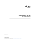
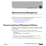
VLAN
INTEROPERABILITY
OF THE DELL™
POWERCONNECT™
M6220
WITH CISCO IOS OR CISCO
CATOS BASED SWITCHES
By Bruce Holmes
THIS WHITE PAPER IS FOR INFORMATIONAL PURPOSES ONLY, AND MAY
CONTAIN TYPOGRAPHICAL ERRORS AND TECHNICAL INACCURACIES. THE
CONTENT IS PROVIDED AS IS, WITHOUT EXPRESS OR IMPLIED WARRANTIES OF
ANY KIND.
Dell and PowerConnect are trademarks of Dell Inc. Other trademarks and trade names
may be used in this document to refer to either the entities claiming the marks and
names or their products. Dell disclaims proprietary interest in the marks and names
of others.
©Copyright 2008 Dell Inc. All rights reserved. Reproduction in any manner whatsoever
without the express written permission of Dell Inc. is strictly forbidden. For more
information, contact Dell.
Information in this document is subject to change without notice.
CONTENTS
INTRODUCTION
3
NETWORK ARCHITECTURE OF THE DELL
MODULAR SERVER ENCLOSURE
4
CLEARING THE CONFIGURATION FOR THE
DELL POWERCONNECT M6220 AND CISCO SWITCHES
4
CONFIGURING THE M6220 PORTS FOR STATIC VLANS
6
CONFIGURING THE M6220 EXTERNAL PORTS FOR STATIC VLANS
7
CONFIGURING A CISCO IOS ETHERNET SWITCH FOR STATIC VLANS
12
CONFIGURING A CISCO CATOS ETHERNET SWITCH FOR STATIC VLANS
14
CONFIRMING A SUCCESSFUL STATIC VLAN CONFIGURATION
ON THE POWERCONNECT M6220
15
CONFIRMING A SUCCESSFUL STATIC VLAN CONFIGURATION
WITH CISCO IOS
16
CONFIRMING A SUCCESSFUL STATIC VLAN CONFIGURATION
WITH CISCO CATOS
17
CONFIGURING THE M6220 EXTERNAL PORTS FOR DYNAMIC
VLANS USING GVRP
18
CONFIGURING A CISCO CATOS BASED ETHERNET SWITCH
FOR DYNAMIC VLANS
20
CONFIGURING A CISCO IOS ETHERNET SWITCH FOR DYNAMIC VLANS
21
CONFIRMING A SUCCESSFUL GVRP COMMUNICATION WITH THE M6220
21
CONFIRMING A SUCCESSFUL GVRP COMMUNICATION WITH
CISCO CATOS
22
CONFIRMING A SUCCESSFUL VLAN CONNECTION WITH CISCO IOS
22
VLANS AND LINK AGGREGATION GROUPS
22
VLANS AND SPANNING TREE ON THE M6220
26
COMPARING ACCESS, TRUNK AND GENERAL MODES ON THE M6220
26
CONCLUSION
27
ABOUT THE AUTHOR
27
FIGURES
FIGURE 1: DELL POWERCONNECT M6220 NETWORKING ARCHITECTURE
4
FIGURE 2: VLAN EXAMPLE (USED FOR STATIC AND GVRP EXAMPLES)
6
MSTP INTEROPERABILITY OF THE DELL™ POWERCONNECT™ 6200 SERIES SWITCHES
WITH CISCO IOS AND CISCO CATOS-BASED SWITCHES
INTRODUCTION
This paper describes how to configure the Dell PowerConnect M6220 Gigabit Ethernet switch
to interoperate and connect with Cisco IOS and CatOS-based switches when using industry
standard Virtual Local Area Networks (VLANs) that adhere to the IEEE 802.1Q
standard. This paper discusses both static and dynamic VLANs.
The primary purpose of VLANs is to separate traffic on a network. This separation is
accomplished by adding a VLAN tag to each Ethernet frame and by using switches that can
recognize these tags to keep the traffic with the same tags on the necessary network
segments. Using VLANs conserves network bandwidth by limiting broadcast traffic to a
specified VLAN and provides a more secure network by limiting traffic across multiple VLANs.
The IEEE 802.1Q standard-based VLAN implementation on the PowerConnect M6220 is
interoperable with Cisco VLANs using both static and dynamic configuration (dynamic via
GVRP). Dell is a member of the University of New Hampshire Interoperability Lab (UNH-IOL),
where all PowerConnect products are tested to confirm interoperability with other Consortium
members’ network devices. Included in the UNH-IOL tests is VLAN interoperability with other
Consortium members. Additional information regarding UNH’s VLAN testing can be found at:
ftp://ftp.iol.unh.edu/pub/bfc/testsuites/vlan.io.test.suite.pdf
VLANs can be configured as either dynamic or static. Dynamic configuration is supported
using the IEEE 802.1Q standard, which is known as GARP VLAN Registration Protocol (GVRP).
Static configuration is used when connecting the Dell PowerConnect M6220 Gigabit Ethernet
switch to an external Gigabit Ethernet switch or a NIC that does not support GVRP. One
advantage of GVRP is that the protocol enables the Gigabit Ethernet switches in the network to
automatically add and remove ports from VLANs, thus minimizing network administration.
The following examples use the switch’s Command Line Interface (CLI) for configuration. See
the Dell™ PowerConnect™ M6220 CLI Reference Guide for more detailed information about
the commands. The “VLAN Commands” chapter contains information about configuring VLANs
by using the CLI.
If desired, any of the example configurations can be performed on the Dell PowerConnect
M6220 by using the Web Based Interface (WBI) as well. See the Dell PowerConnect M6220
User's Guide for a description of the Dell WBI. For information about configuring VLANs by
using the WBI, see the “Configuring VLANs” section in the “Configuring Switching Information”
chapter.
The Dell™ PowerConnect™ M6220 CLI Reference Guide and the Dell PowerConnect M6220
User's Guide are located on the Dell support website:
http://support.dell.com/support/edocs/network/PCM6220/en/index.htm
APRIL 2008
3
MSTP INTEROPERABILITY OF THE DELL™ POWERCONNECT™ 6200 SERIES SWITCHES
WITH CISCO IOS AND CISCO CATOS-BASED SWITCHES
Server
Blade 1
g1
Switch
g16
Blade 1
Mid Plane
g1
Switch
Blade 6
Server
Blade 16
g16
External Copper
g17 to g20
HiGig ports
xg1 to xg4
External Copper
g17 to g20
HiGig ports
xg1 to xg4
Internal Port Connections
Figure 1: Dell PowerConnect M6220 Networking Architecture
NETWORK ARCHITECTURE OF THE DELL MODULAR SERVER ENCLOSURE
The internal network architecture of the Dell Modular Server Enclosure is shown in Figure 1.
Each server blade has two LAN on Motherboard (LOM) Ethernet controllers integrated into its
motherboard. Each server blade’s LOM is connected through the chassis midplane to the
chassis I/O bays in the rear. Each Ethernet switch has sixteen internal ports (one to each
server blade, numbered g1-g16) and four external 1G ports (numbered g17-g20) and four
optional 10G ports (numbered xg1-xg4).
CLEARING THE CONFIGURATION FOR THE DELL POWERCONNECT M6220
AND CISCO SWITCHES
The examples in this document show the minimum configurations necessary to configure
VLANs between a Cisco IOS Gigabit Ethernet switch (Catalyst 3750), Cisco CatOS Ethernet
switch (Catalyst 6509), and the Dell PowerConnect M6220. The commands in this example
work without issue when starting from a default configuration of the switches.
To set the Dell PowerConnect M6220 to default configuration and reboot, use the following
commands:
NOTE: This will erase any configuration data previously configured and reboot the switch.
M6220# clear config
M6220# reload
APRIL 2008
4
MSTP INTEROPERABILITY OF THE DELL™ POWERCONNECT™ 6200 SERIES SWITCHES
WITH CISCO IOS AND CISCO CATOS-BASED SWITCHES
From the Web interface, click the Restore Configuration Factory Default option on the
System > File Management > Copy Files page, and then click Apply Changes.
To set a Cisco IOS based switch to default configuration, use the following commands:
NOTE: This will erase any configuration data previously configured and reboot the switch.
3750# delete flash:/config.text
3750# reload
To set a Cisco CatOS based switch (e.g. Catalyst 6509) to default configuration, use the
following commands:
NOTE: This will erase any configuration data previously configured and reboot the switch.
Cat_6509 (enable) clear config all
Please see other sections of this paper for cases when it is impractical to reset the switches to
factory defaults.
The Dell PowerConnect M6220 can support up to 1024 different VLANs. VLAN ID can be
any value between 2-4093 (The default VLAN ID is 1). A VLAN tag can have a value from 2
to 4093.
APRIL 2008
5
MSTP INTEROPERABILITY OF THE DELL™ POWERCONNECT™ 6200 SERIES SWITCHES
WITH CISCO IOS AND CISCO CATOS-BASED SWITCHES
Figure 2: VLAN Example (Used for Static and GVRP Examples)
CONFIGURING THE M6220 PORTS FOR STATIC VLANS
The network scenario in Figure 2 will be used to show how to configure static VLANs (Figure 2
will also be used for the GVRP examples later in this paper). This example will show how to
perform the following tasks:
•
•
•
•
Put the server blade connected to port g1 in VLAN 101
Put the server blade connected to port g2 in VLAN 102
Put server blades connected to ports g3 through g16 in VLAN 310
“Trunk” these VLANs to a Cisco IOS and a Cisco CatOS switch using static VLANs
Port g20 is used as the trunk port in the examples, but this is an arbitrary choice. Any ports
from g17 to g20 could be used for this example.
APRIL 2008
6
MSTP INTEROPERABILITY OF THE DELL™ POWERCONNECT™ 6200 SERIES SWITCHES
WITH CISCO IOS AND CISCO CATOS-BASED SWITCHES
CONFIGURING THE M6220 EXTERNAL PORTS FOR STATIC VLANS
The following example shows the Dell PowerConnect M6220 Gigabit Ethernet switch CLI
commands for configuring the 16 internal ports and external port g20 as shown in Figure 2.
M6220>enable
M6220#configure
M6220(config)#vlan database
M6220(config-vlan)#vlan 101,102,310
M6220(config-vlan)#exit
M6220(config)#interface ethernet
M6220(config-if-1/g1)#switchport
M6220(config-if-1/g1)#exit
M6220(config)#interface ethernet
M6220(config-if-1/g2)#switchport
M6220(config-if-1/g2)#exit
1/g1
access vlan 101
1/g2
access vlan 102
M6220(config)#interface range Ethernet 1/g3-1/g16
M6220(config-if)#switchport access vlan 310
M6220(config-if)#exit
M6220(config)#interface ethernet 1/g20
M6220(config-if-1/g20)#switchport mode general
M6220(config-if-1/g20)#switchport general allowed vlan add 101,102,310
tagged
M6220(config-if-1/g20)#switchport general pvid 4095
M6220(config-if-1/g20)#switchport general allowed vlan remove 1
M6220(config-if-1/g20)#exit
The following table describes the commands used in the previous example.
APRIL 2008
Command
Description
enable
Set the CLI mode to enable privilege mode
configure
Sets the CLI mode to configuration mode
vlan database
Sets the CLI mode to define the static
VLANs
vlan 101,102,310
Defines the static VLANs that are used in
this example
exit
Puts the CLI back into the configuration CLI mode
interface ethernet 1/g1
Sets the CLI mode to configure gigabit ethernet
port 1 (referred to in the command as ‘1/g1’)
NOTE: Value ‘1’ in “1/g1 and 1/g8” specifies
the unit number, this number depends on the
Stack unit number and can be between 1 to 12
switchport access vlan 101
Sets the port to an access VLAN port in
VLAN 101. This means that the Ethernet
traffic on this port will be untagged and all
the traffic will be in VLAN 101
exit
Puts the CLI back into the configuration CLI mode
interface ethernet 1/g2
Sets the CLI mode to configure gigabit
ethernet port 2 (referred to in the command
as ‘1/g2’)
switchport access vlan 102
Sets the port to an access VLAN port in
VLAN 102
7
MSTP INTEROPERABILITY OF THE DELL™ POWERCONNECT™ 6200 SERIES SWITCHES
WITH CISCO IOS AND CISCO CATOS-BASED SWITCHES
Command
Description
exit
Puts the CLI back into the configuration CLI mode
interface range ethernet 1/g3-1/g16
switchport access vlan 310
Sets the CLI mode to configure gigabit
Ethernet ports 3 through 16 (referred to in
the command as ‘1/g3-1/g16’)
Sets ports 1/g3 through 1/g16 to access
ports in VLAN 310
exit
Puts the CLI back into the configuration CLI mode
interface ethernet 1/g20
Sets the CLI mode to configure gigabit
Ethernet port 20 (referred to in the
command as ‘1/g20’)
switchport mode general
Sets the port type to an 802.1Q VLAN.
An 802.1Q VLAN port will allow multiple
tagged VLANs
switchport general allowed vlan
add 101,102,310 tagged
Sets the port to allow only tagged traffic in
VLANs 101, 102, and 310. Traffic with tags
other than 101, 102, or 310 will be dropped
switchport general pvid 4095
Sets the port to put any untagged packets
entering the port into VLAN 4095 (4095 is
the discard VLAN. Setting the PVID to
4095 means that untagged packets are
not allowed on this port)
switchport general allowed vlan
remove 1
Used to remove the port membership from
VLAN ‘1’. By default all the ports on the
switch are members of VLAN ‘1’
exit
Puts the CLI back into the configuration
CLI mode
NOTE: In this example, traffic from the server blades is untagged and put in a specific VLAN at
the switch. The combined traffic from the server blades is then put on the single external
trunked port as tagged traffic. The VLAN tags keep the traffic logically separated. When tagged
traffic enters the external trunked port, the switch examines the tag, removes the tag and
sends the traffic to the destination server blade.
To configure the external ports for static VLANs by using the Web interface, use the following steps.
APRIL 2008
8
MSTP INTEROPERABILITY OF THE DELL™ POWERCONNECT™ 6200 SERIES SWITCHES
WITH CISCO IOS AND CISCO CATOS-BASED SWITCHES
1.
2.
APRIL 2008
From the Switching > VLAN > VLAN Membership page, click Add.
From the Add VLAN page, enter 101 in the VLAN ID field and click Apply Changes.
9
MSTP INTEROPERABILITY OF THE DELL™ POWERCONNECT™ 6200 SERIES SWITCHES
WITH CISCO IOS AND CISCO CATOS-BASED SWITCHES
3.
4.
5.
Add VLANs 102 and 310.
From Ports menu on the Switching > VLAN > Port Settings page, select port g20.
Configure port g20 in General mode with a PVID of 4095 and click Apply Changes.
6.
From the Show VLAN menu on the Switching > VLAN > VLAN Membership page,
select 101.
Click the Static box for port 1 so that the letter U (untagged) appears in the box.
Click the Static box for port 20 so that the letter T (tagged) appears in the box.
Click Apply Changes.
7.
8.
9.
APRIL 2008
10
MSTP INTEROPERABILITY OF THE DELL™ POWERCONNECT™ 6200 SERIES SWITCHES
WITH CISCO IOS AND CISCO CATOS-BASED SWITCHES
10. Select VLAN 102 and assign port 2 to the VLAN as an untagged interface and port 20 as
a tagged interface.
11. Select VLAN 310, and assign ports 3-16 to the VLAN as untagged interfaces and port 20
as a tagged interface.
APRIL 2008
11
MSTP INTEROPERABILITY OF THE DELL™ POWERCONNECT™ 6200 SERIES SWITCHES
WITH CISCO IOS AND CISCO CATOS-BASED SWITCHES
12. Click Apply Changes.
13. Select VLAN 1, and click the Static field for port 20 until it is blank in order to remove
interface 1/g20 from VLAN 1.
14. To view the VLAN Port Table, open the Switching > VLAN > Port Settings page, and
then click Show All.
CONFIGURING A CISCO IOS ETHERNET SWITCH FOR STATIC VLANS
The following example shows the Cisco IOS Ethernet switch command-line interface (CLI)
commands for configuring its ports as shown in Figure 2.
3750(config)# vtp mode transparent
3750(config)# interface GigabitEthernet 1/0/1
3750(config-if)# switchport access vlan 101
3750(config-if)# exit
3750(config)# interface GigabitEthernet 1/0/2
3750(config-if)# switchport access vlan 102
3750(config-if)# exit
APRIL 2008
12
MSTP INTEROPERABILITY OF THE DELL™ POWERCONNECT™ 6200 SERIES SWITCHES
WITH CISCO IOS AND CISCO CATOS-BASED SWITCHES
3750(config)# interface GigabitEthernet 1/0/3
3750(config-if)# switchport access vlan 310
3750(config-if)# exit
3750(config)# interface GigabitEthernet 1/0/16
3750(config-if)# switchport mode trunk
3750(config-if)# switchport trunk allowed vlan 101-102,310
3750(config-if)# switchport trunk encapsulation dot1q
3750(config-if)# exit
The following table describes the commands used in the example:
APRIL 2008
Command
Description
vtp mode transparent
Sets the switch for static VLAN configuration.
This command disables the VTP protocol.
NOTE: Cisco switches have the Cisco
proprietary VTP (VLAN trunking protocol)
enabled by default. VTP performs the same
function as the IEEE standard protocol GVRP.
The PowerConnect M6220 does not support
the Cisco proprietary VTP and can only work
with ports using IEEE 802.1Q standard GVRP
protocol. Some Cisco switches also support
GVRP. GVRP is discussed later in this
document
interface GigabitEthernet 1/0/1
Sets the CLI mode to configure gigabit
Ethernet port 1 (referred to in the command
as ‘GigabitEthernet 1/0/1’)
switchport access vlan 101
Sets the port to an access VLAN port in
VLAN 101. This means that the Ethernet
traffic on this port will be untagged and all
the traffic will be in VLAN 101
exit
Puts the CLI back into the configuration
CLI mode
interface GigabitEthernet 1/0/2
Sets the CLI mode to configure gigabit
Ethernet port 2
switchport access vlan 102
Sets the port to an access VLAN port in
VLAN 102
exit
Puts the CLI back into the configuration
CLI mode
interface GigabitEthernet 1/0/3
Sets the CLI mode to configure gigabit
Ethernet port 3
switchport access vlan 310
Sets the port to an access VLAN port in
VLAN 310
exit
Puts the CLI back into the configuration CLI mode
interface GigabitEthernet 1/0/16
Sets the CLI mode to configure gigabit
Ethernet port 16 (referred to in the command
as ‘GigabitEthernet 1/0/16’)
13
MSTP INTEROPERABILITY OF THE DELL™ POWERCONNECT™ 6200 SERIES SWITCHES
WITH CISCO IOS AND CISCO CATOS-BASED SWITCHES
Command
Description
switchport mode trunk
Sets the port type to a VLAN trunk. A VLAN
trunk port will allow multiple tagged VLANs
switchport access vlan 102
Puts the CLI back into the configuration CLI mode
switchport trunk allowed vlan 101
-102,310
Sets the port to allow only tagged traffic in
VLANs 101, 102, and 310
switchport trunk encapsulation
dot1q
Sets the port to send and receive 802.1Q
tagged traffic (not the Cisco proprietary ISL
tagged traffic)
exit
Puts the CLI back into the configuration CLI mode
CONFIGURING A CISCO CATOS ETHERNET SWITCH FOR STATIC VLANS
The following example shows the Cisco CatOS Ethernet switch command-line interface (CLI)
commands for configuring its ports as shown in Figure 2.
6509> (enable) set vtp mode transparent
6509> (enable) set vlan 101 2/1
6509> (enable) set vlan 102 2/2
6509> (enable) set vlan 310 2/3
6509> (enable) clear trunk 2/16 1-1005,1025-4094
6509> (enable) set trunk 2/16 on dot1q 101-102,310
The following table describes the commands used in the previous example:
APRIL 2008
Command
Description
vtp mode transparent
Sets the switch for static VLAN configuration.
By default, Cisco switches have the Cisco
proprietary VTP (VLAN trunking protocol)
enabled by default. This command disables the
VTP protocol
set vlan 101 2/1
Sets the port to an access VLAN port in
VLAN 101. This means that the Ethernet
traffic on this port will be untagged and all
the traffic will be in VLAN 101
set vlan 102 2/2
Configures port 2/2 to be an access port in
VLAN 102
set vlan 310 2/3
Configures port 2/3 to be an access port in
VLAN 310
14
MSTP INTEROPERABILITY OF THE DELL™ POWERCONNECT™ 6200 SERIES SWITCHES
WITH CISCO IOS AND CISCO CATOS-BASED SWITCHES
Command
Description
clear trunk 2/16 1-1005,
1025-4094
Disables port 2/16 from carrying all
VLANs. The default VLAN settings of
Cisco CatOS are to allow all VLANs on
trunked ports. This is a security concern.
It is good network configuration practice
to remove a port from all VLANs before
adding it to the desired VLANs.
set trunk 2/16 on dot1q
101-102,310
Sets port 2/16 port type to a VLAN trunk
(noted by ‘trunk’), sets the port to send and
receive 802.1Q tagged traffic (noted by ‘on’)
and sets the port to allow only traffic in
VLANs 101, 102, and 310. A VLAN trunk
port will only allow tagged packets.
CONFIRMING A SUCCESSFUL STATIC VLAN CONFIGURATION
ON THE POWERCONNECT M6220
The following M6220 command can be used to confirm the VLAN configuration:
M6220#show interfaces switchport ethernet 1/g1
Port: 1/g1
VLAN Membership mode:Access Mode
Operating parameters:
PVID: 101
Ingress Filtering: Enabled
Acceptable Frame Type: Untagged
Default Priority: 0
GVRP status:Enabled
Protected:Disabled
Port 1/g1 is member in:
VLAN
----101
Name
-----------
Egress rule
------------Untagged
Type
-----Static
Static configuration:
PVID: 101
Ingress Filtering: Enabled
Acceptable Frame Type: Untagged
Port 1/g1 is statically configured to:
VLAN
----101
Name
-----------
Egress rule
------------Untagged
Type
------
Forbidden VLANS:
VLAN
Name
-------
APRIL 2008
15
MSTP INTEROPERABILITY OF THE DELL™ POWERCONNECT™ 6200 SERIES SWITCHES
WITH CISCO IOS AND CISCO CATOS-BASED SWITCHES
The output of this command shows that port g1 ‘VLAN Membership Mode’ is ‘Access’ and that
the ‘Port is member in’ VLAN 101.
The following is the output of this command for port g20 (the port with VLANs 101,102, 310):
M6220#show interfaces switchport ethernet 1/g20
Port: 1/g20
VLAN Membership mode:General Mode
Operating parameters:
PVID: 4095
Ingress Filtering: Enabled
Acceptable Frame Type: Admit All
Default Priority: 0
GVRP status:Disabled
Protected:Disabled
Port 1/g20 is member in:
VLAN
---101
102
310
Name
----
Egress rule
----------Tagged
Tagged
Tagged
Type
-----Static
Static
Static
Static configuration:
PVID: 4095
Ingress Filtering: Enabled
Acceptable Frame Type: Admit All
Port 1/g20 is statically configured to:
VLAN
---101
102
310
Name
----
Egress rule
----------Tagged
Tagged
Tagged
Forbidden VLANS:
VLAN Name
---- ---The output of this command shows that port g20 ‘VLAN Membership mode’ is ‘General and
that the ‘Port is member in’ VLANs 101, 102, and 310. Also notice that the ‘Ingress UnTagged
VLAN (PVID)’: VLAN is 4095. VLAN 4095 is the discard VLAN and this setting means that
untagged packets entering this port are dropped.
CONFIRMING A SUCCESSFUL STATIC VLAN CONFIGURATION
WITH CISCO IOS
The following Cisco IOS commands can be used to confirm the VLAN configuration:
3750# show interfaces gigabitEthernet 1/0/1 switchport
Name: Gi1/0/1
Switchport: Enabled
Administrative Mode: dynamic auto
Operational Mode: static access
Administrative Trunking Encapsulation: negotiate
Operational Trunking Encapsulation: native
Negotiation of Trunking: On
Access Mode VLAN: 101 (VLAN0101)
. . .
APRIL 2008
16
MSTP INTEROPERABILITY OF THE DELL™ POWERCONNECT™ 6200 SERIES SWITCHES
WITH CISCO IOS AND CISCO CATOS-BASED SWITCHES
The output of this command shows that port 1/0/1 (Name: Gi1/0/1) is in ‘Operations Mode:
static access’ and that is in ‘Access mode VLAN: 101 (VLAN0101)’.
The following is the output of this command for port 1/0/16 (the port with VLANs 101,102, 310):
3750# show interfaces gigabitEthernet 1/0/16 switchport
Name: Gi1/0/16
Switchport: Enabled
Administrative Mode: trunk
Operational Mode: trunk
Administrative Trunking Encapsulation: dot1q
Operational Trunking Encapsulation: dot1q
Negotiation of Trunking: On
Access Mode VLAN: 1 (default)
Trunking Native Mode VLAN: 1 (default)
Voice VLAN: none
Administrative private-vlan host-association: none
Administrative private-vlan mapping: none
Administrative private-vlan trunk native VLAN: none
Administrative private-vlan trunk encapsulation: dot1q
Administrative private-vlan trunk normal VLANs: none
Administrative private-vlan trunk private VLANs: none
Operational private-vlan: none
Trunking VLANs Enabled: 101,102,310
. . .
The output of this command shows that port 1/0/16 (Name: Gi1/0/16) is in ‘Operational Mode: trunk’
and that the ‘Trunking VLANS Enabled’: are 101, 102, and 310. In Cisco IOS when a port is in
VLAN trunk mode, all untagged packets are dropped unless the ‘Trunking Native Mode VLAN’ is
also included as one of the ‘Trunking VLANs’. In this example the ‘Trunking Native Mode VLAN’ is
VLAN 1 but since VLAN 1 was not included in the trunk (via the switchport trunk allowed
vlan command), all untagged traffic entering this port is dropped.
CONFIRMING A SUCCESSFUL STATIC VLAN CONFIGURATION
WITH CISCO CATOS
The following CatOS commands can be used to confirm the VLAN configuration:
6509> (enable) show vlan
VLAN
Name
--------------1
default
101
102
310
1002
1003
1004
1005
. . .
VLAN0101
VLAN0102
VLAN0310
fddi-default
token-ring-default
fddinet-default
trnet-default
Status
------active
IfIndex
------6
active
active
active
active
active
active
active
116
117
121
7
10
8
9
Mod/Ports,Vlans
--------------1/1-2
2/4-15,2/17-48
3/1-8
4/1-48
2/1
2/2
2/3
The output of this command shows that VLAN 101 has port 2/1 as a member port, VLAN 102
has port 2/2 as a member port, and VLAN 310 has port 2/3 as a member port.
APRIL 2008
17
MSTP INTEROPERABILITY OF THE DELL™ POWERCONNECT™ 6200 SERIES SWITCHES
WITH CISCO IOS AND CISCO CATOS-BASED SWITCHES
The following command can be used for port 2/16 (the port with VLANs 101,102, 310):
6509> (enable) show trunk
* - indicates vtp domain mismatch
# - indicates dot1q-all-tagged enabled on the port
Port
Mode
Encapsulation
Status
-------------------------------2/16
on
dot1q
trunking
Port
----2/16
Native vlan
----------1
Vlans allowed on trunk
---------------------101-102,310
. . .
The output of this command shows that port 2/16 has an ‘Encapsulation” of ‘dot1q’, the ‘Status’
is ‘trunking’ and that the ‘VLANs allowed on the trunk’ are 101, 102, and 310. In Cisco CatOS
when a port is in VLAN trunk mode, all untagged packets are dropped unless the ‘Native VLAN
is also included as one of the ‘VLANs allowed on trunk’. In this example the ‘Native VLAN’ is
VLAN 1 but since VLAN 1 was not included in the trunk all untagged traffic entering this port is
dropped.
CONFIGURING THE M6220 EXTERNAL PORTS FOR DYNAMIC
VLANS USING GVRP
NOTE: The following example assumes starting from an empty configuration.
The following example shows the Dell PowerConnect M6220 Gigabit Ethernet switch
command-line interface (CLI) commands for configuring the Gigabit Ethernet switch with
GVRP to match the example in Figure 2.
M6220(config)# vlan database
M6220(config-vlan)# vlan 101-102,310
M6220(config)# exit
M6220(config)# interface ethernet 1/g1
M6220(config-if-1/g1)# switchport access vlan 101
M6220(config-if-1/g1)# gvrp enable
M6220(config-if-1/g1)# exit
M6220(config)# interface ethernet 1/g2
M6220(config-if-1/g2)# switchport access vlan 102
M6220(config-if-1/g2)# gvrp enable
M6220(config-if-1/g2)# exit
M6220(config)# interface range ethernet 1/g3-1/g16
M6220(config-if)# switchport access vlan 310
M6220(config-if)# gvrp enable
M6220(config-if)# exit
M6220(config)# interface ethernet 1/g20
M6220(config-if-1/g20)# switchport mode general
M6220(config-if-1/g20)# switchport general pvid 4095
M6220(config-if-1/g20)# switchport general allowed vlan remove 1
M6220(config-if-1/g20)# gvrp enable
M6220(config-if-1/g20)# exit
M6220(config)# gvrp enable
The only addition is the gvrp enable command for each port. For the access ports (g1, g2,
g3-10) the gvrp enable command configures each port to be advertised by GVRP on any
ports that have GVRP enabled. Conversely VLANs that are only on access ports that do not
have GVRP enabled will not be advertised on ports that have GVRP enabled. For port (g20),
the gvrp enable command configures the port to advertise the VLANs from the ports that
have GVRP enabled (101,102, 310) and learn new VLANs on the port via GVRP.
APRIL 2008
18
MSTP INTEROPERABILITY OF THE DELL™ POWERCONNECT™ 6200 SERIES SWITCHES
WITH CISCO IOS AND CISCO CATOS-BASED SWITCHES
The last GVRP enable command enables GVRP globally.
To perform the same configuration by using the Web interface, navigate to the Switching >
VLAN > GVRP Parameters page.
To enable GVRP on the switch Select Enable from the GVRP Global Status menu and click
Apply Changes.
To enable GVRP on the ports, use the following steps:
1.
2.
3.
4.
APRIL 2008
From the GVRP Parameters page, click Show All.
Select the Edit option for port 1/g1, and then select Enable from the GVRP State menu.
Above the port table, select the Copy Parameters From option and make sure port 1/g1
is selected in the Port field.
Select the Copy To option in the fields for ports 1/g2 – 1/g20 to copy the GVRP Enable
setting from port 1/g1 to those ports.
19
MSTP INTEROPERABILITY OF THE DELL™ POWERCONNECT™ 6200 SERIES SWITCHES
WITH CISCO IOS AND CISCO CATOS-BASED SWITCHES
5.
Click Apply Changes.
CONFIGURING A CISCO CATOS BASED ETHERNET SWITCH FOR
DYNAMIC VLANS
The following example shows the Cisco CatOS Gigabit Ethernet switch command-line interface
(CLI) commands for configuring the Cisco switch with GVRP to match the example in Figure 2.
6509>
6509>
6509>
6509>
6509>
6509>
6509>
6509>
6509>
APRIL 2008
(enable)
(enable)
(enable)
(enable)
(enable)
(enable)
(enable)
(enable)
(enable)
set vtp mode transparent
set vlan 101 2/1
set vlan 102 2/2
set vlan 310 2/3
set trunk 2/16 on dot1q
set port gvrp 2/16 enable
set gvrp dynamic-vlan-creation enable
set gvrp enable
clear trunk 2/16 1
20
MSTP INTEROPERABILITY OF THE DELL™ POWERCONNECT™ 6200 SERIES SWITCHES
WITH CISCO IOS AND CISCO CATOS-BASED SWITCHES
Command
Description
set vtp mode transparent
Sets the switch to ignore, but forward the
Cisco proprietary VTP (VLAN Trunking
Protocol). VTP is used to perform similar
functions as GVRP, but it is not compatible
with GVRP
set vlan 101 2/1
Configure port 2/1 to be an access port in
VLAN 101
set vlan 102 2/2
Configure port 2/2 to be an access port in
VLAN 102
set vlan 310 2/3
Configure port 2/3 to be an access port in
VLAN 310
set trunk 2/16 on dot1q
Sets port 2/16 to use 802.1Q encapsulation
for VLAN tagged traffic (not the Cisco
proprietary ISL encapsulation)
set port gvrp 2/16 enable
Enable GVRP on port 2/16
set gvrp dynamic-vlan-creation
enable
Configures the switch to dynamically create
VLANs learned via GVRP
set gvrp enable
Enables GVRP on the switch globally
clear trunk 2/16 1
Prevents VLAN 1 from being advertised via
GVRP. VLAN 1 is the default VLAN. Any
ports not configured to be in a specific VLAN
will be put in VLAN 1. This shows how to
prevent traffic from ports left in the default
state from sending traffic across the trunk
CONFIGURING A CISCO IOS ETHERNET SWITCH FOR DYNAMIC VLANS
Very few IOS based switches support GVRP. This section will be updated at a later time.
CONFIRMING A SUCCESSFUL GVRP COMMUNICATION WITH THE M6220
The following example shows how the PowerConnect M6220 show vlan command can be
used to assure that the M6220 is learning VLAN information via GVRP.
M6220# show vlan
VLAN
Name
----- -------1
Default
Ports
------ch1-18,
1/g3-1/g20,
1/xg1-1/xg4
1/g1
1/g2
1/g3-1/g16,
1/g20
Type
------Default
Authorization
------------Required
Static
Static
Static
Required
Required
Required
VLAN
Name
----- --------
Ports
-------
Type
-------
Authorization
-------------
1
101
102
310
g(11-15),ch(1-8)
g1
g2
g(3-10,16)
other
permanent
permanent
permanent
Required
Required
Required
Required
101
102
310
APRIL 2008
1
101
102
310
21
MSTP INTEROPERABILITY OF THE DELL™ POWERCONNECT™ 6200 SERIES SWITCHES
WITH CISCO IOS AND CISCO CATOS-BASED SWITCHES
The output of this command shows that VLAN 310 contains ports g3-g16 and port g20. In the
example ports g3-16 were configured statically to be members of 310. Port g20 was learned
via GVRP. The configuration of the Cisco switches will not advertise the access port VLANs
across port g20 unless the access port has link. So the output of the above command implies
that the Cisco switch does not have link on port 1 and 2, but does have link on port 3.
CONFIRMING A SUCCESSFUL GVRP COMMUNICATION WITH CISCO CATOS
The following example shows how the Cisco CatOS show trunk 2/16 command can be
used to assure that the Cisco switch is learning VLANs via GVRP.
6509> (enable) show trunk 2/16
* - indicates vtp domain mismatch
# - indicates dot1q-all-tagged enabled on the port
Port
Mode
Encapsulation
Status
Native vlan
-----------------------------------2/16
on
dot1q
trunking
1
Port
---2/16
Vlans allowed on trunk
---------------------2-1005,1025-4094
Port
---2/16
Vlans allowed and active in management domain
--------------------------------------------101-102,310
Port
---2/16
Vlans in spanning tree forwarding state and not pruned
-----------------------------------------------------310
The output of this command shows that the trunk port 2/16 has learned VLAN 310. In the
example, port 2/3 was configured statically to be a member of VLAN 310. Port 2/16 was added
to VLAN 310 via GVRP. The configuration for the PowerConnect M6220 in the example will not
advertise VLAN 310 unless one of the access ports g(3-10) has link. So the output of the
command implies that the PowerConnect switch does not have link on port g1 and g2, but
does have link on at least one of the ports g(3-10).
CONFIRMING A SUCCESSFUL GVRP VLAN CONNECTION WITH CISCO IOS
Very few IOS based switches support GVRP. This section will be updated at a later time.
CONFIGURATION LIMITATIONS
None
VLANS AND LINK AGGREGATION GROUPS
On the PowerConnect M6220, when members are added to a link aggregation group (LAG),
they are removed from all existing VLAN memberships. When members are removed from a
LAG, they are added back to the VLANs that they were previously members of as per the
configuration file.
NOTE: A port’s VLAN membership can still be configured when it is a member of a LAG;
however, this configuration is only actually applied when the port leaves the LAG. Additionally,
the port’s GVRP configuration is overridden by the LAG’s GVRP configuration. Upon leaving
the LAG, the port will restore its GVRP configuration. The LAG interface can be a member of a
VLAN complying with IEEE 802.1Q.
The following discussion assumes an understanding of LAGs Please see the white paper “Link
Aggregation Interoperability of the Dell PowerConnect™ M6220 with Cisco IOS or Cisco CatOS
based Switches” for a in-depth discussion of M6220 LAG interoperability with Cisco switches.
APRIL 2008
22
MSTP INTEROPERABILITY OF THE DELL™ POWERCONNECT™ 6200 SERIES SWITCHES
WITH CISCO IOS AND CISCO CATOS-BASED SWITCHES
When configuring a LAG to be in a VLAN, the concept for the PowerConnect M6220 is that
ports are put into a LAG, and then the LAG is configured with the desired VLAN settings (not
the individual ports). If the example in Figure 2 were changed slightly, where port g20 was a
LAG of ports g17 and g18 instead of a single port, the M6220 static configuration would look
like this (starting from an empty configuration):
M6220(config)# vlan database
M6220(config-vlan)# vlan 101,102,310
M6220(config-vlan)# exit
M6220(config)# interface ethernet
M6220(config-if-1/g1)# switchport
M6220(config-if-1/g1)# exit
M6220(config)# interface ethernet
M6220(config-if-1/g2)# switchport
M6220(config-if-1/g2)# exit
1/g1
access vlan 101
1/g2
access vlan 102
M6220(config)# interface range ethernet 1/g3-1/g10
M6220(config-if)# switchport access vlan 310
M6220(config-if)# exit
M6220(config)# interface range ethernet 1/g17-1/g18
M6220(config-if)# channel-group 1 mode on
M6220(config-if)# exit
M6220(config)# interface port-channel 1
M6220(config-if-ch1)# switchport mode general
M6220(config-if-ch1)# switchport general allowed vlan add 101,102,310 tagged
M6220(config-if-ch1)# switchport general allowed vlan remove 1
M6220(config-if-ch1)# switchport general pvid 4095
M6220(config-if-ch1)# exit
Only the bold lines were added or changed. The interface range ethernet 1/g17-1/g18
command changes the CLI mode to configure ports g17 and g18. The channel-group 1
mode on command puts ports g17 and g18 into a static LAG. The interface
port-channel 1 command changes the CLI mode to configure LAG 1. All the other lines
are exactly the same as the static VLAN example.
To assign ports 1/g17 and 1/g18 to LAG 1 by using the Web interface, navigate to the
Switching > Link Aggregation > LAG Membership page.
In the Ports area, click the button under port 1/g17 and 1/g18 in the LAG row. The number 1
appears to indicate that the port belongs to LAG 1.
APRIL 2008
23
MSTP INTEROPERABILITY OF THE DELL™ POWERCONNECT™ 6200 SERIES SWITCHES
WITH CISCO IOS AND CISCO CATOS-BASED SWITCHES
To configure the VLAN membership information for LAG 1, use the following steps:
APRIL 2008
1.
2.
3.
4.
Navigate to the Switching > VLAN > LAG Settings page.
Set the Port VLAN Mode to General.
Enter 4095 in the PVID field.
Click Apply Changes.
5.
6.
7.
Navigate to the Switching > VLAN > VLAN Membership page.
From the Show VLAN menu, select 1.
Remove LAG 1 from the VLAN 1 membership and apply the changes.
24
MSTP INTEROPERABILITY OF THE DELL™ POWERCONNECT™ 6200 SERIES SWITCHES
WITH CISCO IOS AND CISCO CATOS-BASED SWITCHES
8.
Select the other VLANs and add LAG 1 as a tagged member.
The concept for Cisco IOS is the same as for the M6220. Ports are put into a LAG and then the LAG
is configured with the desired VLAN settings. If the example in Figure 2 were changed slightly,
where port 1/0/16 was a LAG of ports 1/0/11 and 1/0/12 instead of a single port, the Cisco IOS static
configuration would look like this (starting from an empty configuration):
3750(config)# vtp mode transparent
3750(config)# interface GigabitEthernet 1/0/1
3750(config-if)# switchport access vlan 101
3750(config-if)# exit
3750(config)# interface GigabitEthernet 1/0/2
3750(config-if)# switchport access vlan 102
3750(config-if)# exit
3750(config)# interface GigabitEthernet 1/0/3
3750(config-if)# switchport access vlan 310
3750(config-if)# exit
3750(config)# interface range GigabitEthernet 1/0/11 - 12
3750(config-if)# channel-group 1 mode on
3750(config-if)# exit
3750(config)# interface Port-channel 1
3750(config-if)# switchport mode trunk
3750(config-if)# switchport trunk allowed vlan 101-102,310
3750(config-if)# switchport trunk encapsulation dot1q
3750(config-if)# exit
Only the bold lines were added or changed. The interface range Gigabit Ethernet
1/0/11 – 12 command changes the CLI mode to configure ports 1/0/11 and 1/0/12. The
channel-group 1 mode on command puts ports 1/0/11 and 1/0/12 into a static LAG. The
interface Port-channel 1 command changes the CLI mode to configure LAG 1. All the
other lines are exactly the same as the static VLAN example.
The concept for CatOS is that all individual ports are configured for their VLAN settings and
then the ports are put into a LAG. If the example in Figure 2 were changed slightly, where port
2/16 was a LAG of ports 2/11 and 2/12 instead of a single port, the Cisco IOS static
configuration would look like this (starting from an empty configuration):
6509> (enable) set vtp mode transparent
6509> (enable) set vlan 101 2/1
6509> (enable) set vlan 102 2/2
6509> (enable) set vlan 310 2/3
6509> (enable) clear trunk 2/11,2/12 1-1005,1025-4094
6509> (enable) set trunk 2/11 on dot1q 101-102,310
6509> (enable) set trunk 2/12 on dot1q 101-102,310
6509> (enable) set port channel 2/11,2/12 mode on
Only the bold lines were added or changed. The clear trunk 2/11,2/12 1-1005,1025
-4094 command disables all undesired VLANS from being allowed on the two ports
(2/11,2/12) being put into the LAG. The set trunk 2/11 on dot1q 101-102,310 and
set trunk 2/11 on dot1q 101-102,310 commands put the two ports (2/11,2/12) being
put into the LAG into VLANs 101, 102, and 310. The set port channel 2/11,2/12 mode
on command puts ports 2/11 and 2/12 into a static LAG. All the other lines are exactly the
same as the static VLAN example.
APRIL 2008
25
MSTP INTEROPERABILITY OF THE DELL™ POWERCONNECT™ 6200 SERIES SWITCHES
WITH CISCO IOS AND CISCO CATOS-BASED SWITCHES
VLANS AND SPANNING TREE ON THE M6220
The PowerConnect M6220 implements a Multiple Spanning Tree Protocol instance per switch.
By default the Spanning Tree Protocol is enabled (in RSTP mode) and a single instance of
STP (CIST) will be active. In this case (default configuration), the user should be aware that
even if the network is segmented into multiple VLANs with loops in any particular VLAN, if a
physical loop exists in the network, some ports may be disabled preventing complete network
connectivity. This is a well understood behavior of a single Spanning Tree Protocol instance.
Please see the white paper “MSTP Interoperability of the Dell PowerConnect™ M6220 with
Cisco IOS or Cisco CatOS based Switches” for an in-depth discussion of M6220 Multiple
Spanning Tree (MSTP) interoperability with Cisco switches.
COMPARING ACCESS, TRUNK AND GENERAL MODES ON THE M6220
The PowerConnect M6220 supports three different VLAN modes. The modes and their
definition are as follows:
•
Access mode VLAN
•
By default sets egress to untagged
•
Supports single VLAN configuration only
•
Automatically sets PVID (native VLAN, ingress untagged) to configured VLAN
•
Will accept untagged packets or tagged packets with VLAN ID to which the port is a
member - in this case the port is a member of only one VLAN.
•
Trunk mode VLAN
•
By default sets egress to tagged
•
Supports multiple VLANs
•
Does not set PVID (native VLAN, ingress untagged)
•
Native VLAN cannot be a configured Trunk VLAN or 4095 (discard VLAN).
•
General mode VLAN
•
By default sets egress to tagged
•
Supports multiple VLANs
•
Does not set PVID (native VLAN, ingress untagged)
•
Native VLAN can be any defined VLAN
•
Setting the PVID removes default vlan (VID=1) for that port
•
PVID can be 4095 (discard VLAN)
•
Allows mix of tagged and untagged VLANs in the egress direction.
Access and Trunk modes are short hand for configurations that can be accomplished in
General mode.
The following command example shows the equivalent Access and General mode configurations:
Access Mode:
M6220(config)# interface ethernet 1/g1
M6220(config-if-1/g1)# switchport mode access
M6220(config-if-1/g1)# switchport access vlan 101
M6220(config-if-1/g1)# exit
is equivalent to the following General mode settings:
M6220(config)# interface ethernet 1/g1
M6220(config-if)# switchport mode general
M6220(config-if)# switchport general allowed vlan add
101 untagged
M6220(config-if)# switchport general pvid 101
M6220(config-if)# exit
The following shows the equivalent Trunk and General mode configurations:
Trunk mode:
M6220(config)# interface ethernet 1/g20
M6220(config-if-1/g20)# switchport mode trunk
M6220(config-if-1/g20)# switchport trunk allowed vlan
add 101,102,310
M6220(config-if-1/g20)# switchport trunk native 1
M6220(config-if-1/g20)# exit
APRIL 2008
26
MSTP INTEROPERABILITY OF THE DELL™ POWERCONNECT™ 6200 SERIES SWITCHES
WITH CISCO IOS AND CISCO CATOS-BASED SWITCHES
is equivalent to the following General mode settings:
M6220(config)# interface ethernet 1/g20
M6220(config-if-1/g20)# switchport mode general
M6220(config-if-1/g20)# switchport general allowed vlan
add 101,102,310 tagged
M6220(config-if-1/g20)# switchport general pvid 1
M6220(config-if-1/g20)# exit
The examples discussed in this document use General mode VLANs and not Trunk Mode
VLANs. This is done deliberately so that the PVID could be set to 4095 (discard VLAN) to
disallow untagged packets from entering port g20. Trunk mode ports to not allow the Native
VLAN to be set to 4095.
CONCLUSION
The standards-based VLAN feature on the Dell PowerConnect M6220 switch interoperates
easily with Cisco IOS and CatOS based switches. By understanding the differences in the Dell
PowerConnect M6220 CLI and the Cisco CLIs and building on the examples shown in this
article, system administrators can integrate the M6220 into their Cisco-based networks.
ABOUT THE AUTHOR
Bruce Holmes is a senior project engineer in the Dell PowerConnect Group. He has worked at
Dell for two years and supports Dell PowerConnect switches in all phases of product
development and testing. Prior to Dell, Bruce was an embedded networking software engineer
at Wind River Systems, Alcatel and Texas Instruments. He has a B.S. in Electrical
Engineering from The University of Texas at Austin.
APRIL 2008
27