1
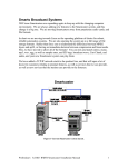
“HOW TO” SERIES
HOW TO INSTALL THE BROADCAST TOOLS GPI 32 WITH
LOGGER/ONAIR
NOVEMBER 2007
OVERVIEW
OMT Technologies is always searching and testing the latest in cost
effective interfacing hardware with our software solutions to provide
exceptional value in your OMT software purchase. Software such as
ONAIR and Logger are powerful automation and audio solutions that
are enhanced with simple and reliable hardware interfacing devices.
The GPI 32 device from Broadcast Tools is a 32 input closure only
device capable of interfacing directly through you RS 232 COM port or
through a USB port with supplied SMART cable (USB to 9 PIN).
Installation is simple and executes the same “PIP” commands that
OMT software code for the SRC 32 Broadcast Tools device. This is a
simple and cost effective way to utilize the USB port on your ONAIR or
Logger computer and provide up to 32 input closures, especially when
most new computers are relying on USB only for external serial
communication.
GPI are clearly labeled on the back of the GPI 32 showing all inputs
and common connections and are contained on two connectors with 16
closures on each. The GPI 32 allows for wall or rack mount
installation.
This device is equally suited for interfacing with StarGuide II/III
receivers as there is are two DB37 ports on the back of the GPI 32 for
direct connection to the receiver.
We hope you find this guide and all other documentation available for
OMT software useful. Please contact [email protected] for any
questions or concerns regarding the installation of this unit with your
Media Touch software.
This document is brought to you by the OMT Support Team.
INSTALLATION
Please read the Broadcast Tools GPI 32 manual before installing this
device as it will provide an outline of how the device functions and its
requirements. The following is an excerpt from the Broadcast Tools
manual.
The GPI-32 interfaces 32 optically isolated inputs to a users PC's RS-232 or USB port. The
serial data conforms to our standard switcher PIP format. The GPI-32 is equipped with dual
plug-in Euroblock connectors and two independent DB-37 connectors that may be interfaced
directly to the DB-37 connectors located on the StarGuide II/III relay cards. Additional
features: dual RS-232 connectors, one for daisy-chaining multiple units on the same legacy
serial port and a DB-9 to interface to our supplied USB adapter; LED indicators for power and
input activity; twin power connectors allowing up to four units to be driven off of one power
transformer. The GPI-32 is supplied with two 3-foot mating DB-37 connecterized cables, serial
cable and wall transformer. The GPI-32 is powered by a surge protected internal power
supply. The GPI-32 may be mounted on the optional RM-3 mounting shelf.
Maintain proper installation techniques including UPS, static and
lightning protection and proper wiring standards. If you are running
extender cables, be sure to take RF, line voltage, distances and proper
shielding techniques into consideration as this can affect the
performance of both out software and this device.
BEFORE POWERING UP THE GPI 32
There are two Phillip #2 screws on the top of the Broadcast Tools unit
that will need to be removed to adjust the “DIP” switches. Switch 5
and 6 should be set in the up or on position and remaining switches in
their default or off state. Replace the cover when complete.
BEFORE YOU CONNECT THE GPI 32 TO YOUR COMPUTER VIA
USB TO 9 PIN CABLE
You can save time by downloading the Virtual Com Port driver (VCP) to
a folder on your ONAIR or Logger computer. “Unzip” or “Extract” the
USB Serial driver files before rebooting your computer with the
hardware attached. You will require a USB Serial device driver and
OMT Support have verified that Royalty Free drivers are available at:
http://www.ftdichip.com
The CDM 2.02.04 has been verified and used in this guide.
Create a folder on the “C:\” root or convenient location to save the
driver file. Extract the file in the same folder location.
NOW YOU CAN CONNECT
Be sure to connect the USB cable and power supply to the GPI 32
while the computer you are connecting to is “off”. Verify that the
power is on the GPI 32 device and this can be determined by the
green led beside the power cord jack.
Power up the computer and your Windows operating system should
find new hardware.
Do not allow Windows to install automatically, rather, specify a
location and point to the folder location where you have extracted the
zip driver files. Windows should now recognize the driver and install
successfully.
To verify, right click “My Computer” from the desktop and double click
device manager. There should be no warnings or errors in any of the
devices listed.
Double click on Ports (COM & LPT) and verify there is a USB serial
device driver installed.
You may want to change the COM port that the new USB serial driver
is currently on to ensure the available ports are sequential, especially
if you are adding additional serial ports through a PCI card or USB
device.
To change the COM port to a different value, double click on the USB
Serial Port from the Ports (COM & LPT) section of the Device Manager.
Select the Port Settings” tab and click on “Advanced”. This example
shows the port active on COM 3. Be sure to save your “Bits per
second” at 9600 baud rate as it may be created at 2400 when
Windows first installs the new port.
The following screen will allow you to select an open or available COM
port in Windows.
The above example is changing COM 3 to COM 2. After you click “OK”,
you should see the following screen showing the correct COM port
number in the display.
Reboot the computer as the COM port will need to be reinitialized
through Windows. Now you are ready to configure your Media Touch
ONAIR or Logger upon restart.
ONAIR CONFIGURATION
To configure the ONAIR application we will click on the iMediaTouch
logo at the top right corner of the ONAIR main screen.
You should now see the two rows of buttons at the bottom of the
following page. The bottom row, middle button will be labeled
“Workstation”.
Select workstation and then select “Security Level 3” from the buttons
on the right hand side of the page.
You will be prompted for a password. The default password is “omt” in
lower case. If this password does not change the page you are
currently on then you will require the password set by your system
administrator.
Select the button labeled
displayed.
and the general page should be
Select
to the right of the
button and select the SRC 32
option at the bottom left corner of the page. Enable the appropriate
COM port value that you have previously installed with the USB Serial
device.
Click
select
at the bottom right corner of the workstation page then
. If you do not have feeds ready to assign closure, please see
the ONAIR user getting started guide available online along with all
OMT software guides at www.imediatouch.com/help.
There are 28 available tally positions to assign input closure for use
with the “Showlog” page.
A Showlog Tally Button1 closure assignment would “fire” the audio
assigned to the top left corner of your Showlog page from the main
ONAIR screen. Under Closure inputs and Start, select SRC 1 for the
SHOW 1 feed entry. You do not have to assign closure SRC 1 with
Show tally 1 as this was kept sequential to make it easy to remember
which button position has been assigned what closure.
Example of audio assigned to button position 1 of the Showlog page.
It is always a good idea to create a “test” Showlog page with audio
assignments in all available 28 button positions to verify closure and
wiring is correct. Make sure that you enable the Showlog Tally so it is
“On” or the input closures will not be recognized when testing. It does
not take long to assign the show tally in the feeds section and this will
ensure all wiring and closures are functioning correctly. If you are not
using the GPI 32 for show tally closure and only for feed related
events, then you will apply the corresponding SRC closure number to
the “EOM” field. This allows ONAIR to end the feed in question and
fire the next log based event while in “Auto ON” mode.
Example of a closure assigned to a feed event.
Feed creation and how to schedule satellite automation information is
available through our website at www.imediatouch.com/help
LOGGER CONFIGURATION
Once the VCP software is installed (see previous driver setup),
configuring Logger is relatively simple. Start the Logger application
and from the top left corner, click on “Configure” then “Hardware”.
You should see the following display.
Enable the SRC 32 device as the input codes are the same as the GPI
32 and select the appropriate COM port. You will need to restart your
Logger application once you have saved your configuration settings.
Under “Feeds” from the main Logger display, select the feed you wish
to apply closure and configure under “Input Closures” and select the
SRC 32 device from the drop down list of closure devices available.
Verify you are receiving all closures through the “Event Log” tab form
the Logger main display. From the top left corner of the main Logger
display, select “Tools’ then “Configure” and enable all events Logging
from the “Administration” tab.
Special Notes:
Be sure to select “COM 1” on the SRC 32 under the Hardware device
selection on versions 2.6.1 and older. Versions 2.6.2 and later will
have a revision to allow other COM ports to be selected.
When finished, click
and
. Remember to restart the
Logger application so the changes will take effect.
TROUBLESHOOTING
Log Tools software along with ONAIR full log display provides an
effective way to verify your closures are configured and working
correctly in your ONAIR application. The out log generated by the
ONAIR software will show all closure events once the setting.ini file
tally entry has been enabled.
TO ENABLE TALLY DIAGNOSTIC
from the
Shut down the ONAIR application and double click
desktop. Find the “C” drive and double click and look for a folder
labeled “Oplog”. In the Oplog folder you will find a file labeled
“Setting.ini”. Double click this file and it will open under notepad or
wordpad. About half way down the page displayed, you will see a
section titled DIAGNOSTICS.
Set the “tally=0” value to 1 and save the file.
Start the ONAIR application as per usual and both the full log display
and the out log file will now display closure entries received.
Example of the full log display in ONAIR
Out log example viewed through Reporter in Log Tools
Enabling the Tally diagnostic can eliminates hours of troubleshooting
and guesswork when trying to verify that our software can
communicate with the Broadcast Tools device and has received a valid
closure. The full log display and out log file will also show connection
to a specific port for a specific device.
HYPERTERMINAL
If you are unsure if your Broadcast Tools GPI 32 device is
communicating over the specified port, Hyper Terminal is a simple way
to show the communication on a specific COM port.
To use Hyper Terminal, go to the
button and select Program
then Accessories, Communications, then Hyper Terminal.
The following screen upon starting Hyper Terminal may ask you to
make this the default Telnet program and ask for the Telephone Area
code in your area. Once completed, you should see this screen.
Give an appropriate name for the connection such as TEST and
click
.
Select the COM port you have the GPI 32 device
connected to and click
.
Be sure to set the COM port to 9600 from the default of 2400 then
click
and
.
Force a closure at input 1 through 16 on the first block (J5) and 17
through 32 on the second block (J6) starting with the first connector
position on the GPI 32. There are two common connections on each
block and they are the two connections farthest to the right hand side
of the plug looking from the back of the unit. They are generally
green in color and will have a “lug” type set screw. There are two DB
37 connectors on the back also and you may install a straight through
StarGuide II/III to GPI 32 cable for convenience. Either connection
will produce the same results.
The screen shot below shows the ASCII text on the Hyper Terminal
screen for the first 16 closures that were manually forced. If you are
not seeing any text on the screen, verify that the GPI 32 DIP switch
settings have position 5 and 6 in the up or on position and the rest of
the switches down or in the off position. Also verify your settings
including COM port are correct in Hyper Terminal.
If you can see populating the field then you have verified the COM is
working correctly. If the closures are not being recognized with a
functional COM port, then verify your configuration settings are set
properly in ONAIR or Logger.
To Recap:
Install the Virtual Serial Driver required for the supplied USB cable.
Select the COM port you have configured for the VCP (Virtual COM
Port). Configure the closure device in either ONAIR or Logger as the
SRC 32. The GPI 32 uses the same “PIP” codes as used with the SRC
32.
We hope you find this guide useful. If you have any questions or
comments about this guide you can contact OMT support at 1-800726-2635 or Sales at 1-888-665-0501.
For iMediaTouch system design and support:
Rick Landry
Support/Integration Manager
[email protected]
OMT Support
1-800-726-2635
To report a bug or place a feature request:
Kevin Kowal
QA and Product Management
[email protected]
To purchase iMediaTouch Software:
1-888-665-0501
Jackie Tetlock
Sales Manager
[email protected]
To purchase iMediaTouch Support:
Kim Arnold
Support Administrator
[email protected]