1
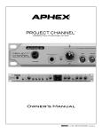
CHANNEL™
MASTER PREAMP & INPUT PROCESSOR
THE COMPLETE CHANNEL STRIP FOR VOICE AND INSTRUMENTS
Owner’s Manual
SAFETY DECLARATIONS
CAUTION: For continued protection against risk of fire, replace only with the same type and rating of fuse.
ATTENTION: pour une protection continue contre les risques d’incendie, ne remplacer qu’avec la même valeur et
même type de fusible.
WARNING: Do not place objects containing liquid on this unit as it is not designed to protect against spillage. Do
not expose this unit to dripping or splashing of liquids as the unit is not designed to protect against these occurances.
WARNING: This unit must be connected to a mains socket outlet with a protective earthing connection.
WARNING: The Exciter has been tested and meets the FCC, CE and European Union rules, regulations, and guidlines for use. Do not attempt to modify or change the Exciter, as this could void the regulator y compliance, which
would place you at risk of losing your authority to operate the Exciter.
WARNING: Do not place objects on top of this unit if they weigh more than 10 pounds.
This equipment has been tested and found to comply with the limits for a Class B digital device, pur suant to part
15 of the FCC rules. These limits are designed to provide reasonable protection against harmful inter ference in a
residential installation. This equipment generates, uses and can radiate radio frequency energy and, if not installed
and used in accordance with the instructions, may cause harmful interference to radio communications. However,
there is no guarantee that interference will not occur in a particular installation. If this equipment does cause
harmful interference to radio or television reception, which can be determined by turning the equipment off and
on, the user is encouraged to try to correct the interference by one or more of the following measures.
1.
Reorient or relocate the receiving antenna.
2.
Increase the separation between the equipment and receiver.
3.
Connect the equipment into an outlet on a circuit different from that to which the receiver is connected.
4.
Consult the dealer or an experienced radio/TV technician for help.
Page 2
TABLE OF CONTENTS
1.0 CONTROLS & INDICATORS
2.0 INSTALLATION AND INTERFACING
2.1 Installation
2.2 AC Line Connection
2.3 Mic Input Connections
2.4 Insert Jacks
2.5 Output Connections
2.6 Digital Audio Outputs
2.7 Word Clock
2.7.1 INT/EXT
2.7.2 WC IN
2.7.3 WC OUT
2.7.4 Local Clock Mastering
2.8 Power Supply
2.9 Cough Switch
3.0 USING THE CHANNEL
3.1 Using the Mic Input
3.2 Using the Instrument Input
3.3 Using Phantom Power
3.4 Using the Polarity Switch
3.5 Using the Pad
3.6 Using the Low Cut
3.7 Using the Phase Rotator
3.8 Using the Compressor
3.9 Using the Logic Assisted Gate
3.10 Using the De-esser
3.11 Using the Equalizer Block
3.11.1 Big Bottom
3.11.2 Parametric Equalizer
3.11.3 Aural Exciter
3.12 Using the Level Control
3.13 Clip Light
4.0 WARRANTY AND SERVICE
4.1 Limited Warranty
4.2 Service Information
5.0 SPECIFICATIONS
5.1 General Specifications
5.2 Architectural Specifications
5.3 Patent Notice
4
6
6
6
6
7
7
7
7
7
7
7
7
7
8
8
8
8
9
9
9
9
9
10
10
10
10
10
10
10
11
11
12
13
14
Copyright 2011 by Aphex. All rights reserved. All Aphex products are trademarks or registered trademarks of Aphex. Other brand and product names are trademarks or registered trademarks of their respective holders.
Page 3
1.0 CONTROLS AND INDICATORS
POWER INDICATION
The Aphex logo above the power switch glows yellow during the tube
preamp’s warm-up time and green when the unit is ready.
LOW NOISE MIC PRE
The Channel works with all professional microphones. The clean and
stable 48V phantom supply is suitable for even the most expensive
microphones. The 12dB/octave low cut filter starts at 70Hz to effectively reduce wind blast without diminishing voice body. Included is
a selectable phase rotator following the principles of the Spectral
Phase Refractor (SPR) circuit. The main benefit of the Phase Rotator is that by making certain voice waveforms more symmetrical, the
compressors action becomes more efficient. This allows for a more
optimized output level.
COMPRESSOR
The Channel includes a special version of Aphex’s patented
Easyrider™ Compressor which has proven to be outstanding. It is
very simple to use with only two controls: Gain/Drive and Release. To
get deeper compression, turn up more Gain. To manage the density
and loudness, work with Release. Faster is louder and denser. Slower
is more natural and open. Note that turning up the Gain/Drive to
get more compression alters the overall gain structure through the
device such that the output may need compensating adjustment.
DE-ESSER
Using a split-band technique with Linkwitz-Riley crossovers, the voice
remains bright and sharp, never losing presence while de-essing. The
de-ess threshold control lets you chose the essing level that you want.
EQUALIZATION BLOCK
A fully parametric equalizer band is provided along with the popular
Aphex Big Bottom and Aural Exciter. These features increase power,
punch and intelligibility without adding noise or an increase in
output level. As a real plus, they are also very easy to adjust.
REAR INSERT JACK
Allows you to insert any kind of line level audio equipment into the
signal path between the Channel’s dynamics processing and the
equalizer section. The operating level at this jack is 0dBu. You should
set up your inserted outboard gear accordingly.
METERS
Meters are provided for peak output level (relevant to both analog
and digital headroom at 0dB = max before clip) and the compressor’s gain reduction. The output level bar graph will move upwards
indicating level, and the gain reduction bar graph will move downwards indicating gain reduction.
OUTPUT CONTROL
LOGIC ASSISTED GATE™
Once triggered, even by a microscopic transient, the signal progresses fully through the attack, hold, and release sequence. This
virtually eliminates the chatter experienced with other gate products.
The attenuation depth and gating threshold are user adjustable to
allow for varying requirements.
Once all processing and equalization is set where you want it, the
output level may need to be adjusted. Do not let the peak level frequently exceed -6dBFS. This will make sure the digital output carries well through subsequent mixing and processing. When using
the analog output, adjust the level to produce the desired average
output level (0VU) as seen on the outboard equipment’s meters.
48V
When pressed,
turns on the microphone phantom
48V power
IINSTRUMENT INPUT
Allows connection of
a guitar or
bass.
Page 4
GAIN/DRIVE
Adjusts
preamp gain
and drive into
the compressor.
Lo Cut
Switches on
the 70Hz Low
Cut filter.
Invert Polarity
When
pressed,
inverts the
polarity
(phase) of the
mic input.
CLIP/MUTE
Flashes yellow when the
preamp is muted by the
cough switch. Flashes red
indicating clipping.
Phase Rotator
Enables the
Spectral Phase
Refractor
to improve
speech symmetry.
PAD
When pressed,
turns on the 20dB
input pad.
Compressor
Turns on the
Easyrider
compressor
circuit.
GATE THRESHOLD
When the sound is higher than this level,
the gate opens up instantly. No “chattering” thanks to the patented Logic
Assisted Gate.
RELEASE
Controls the
density of
compression.
Slow for natural
leveling and
fast for more
loudness.
REAR PANEL ANALOG CONNECTIONS
BALANCED
TRS
MIC INPUT
Works with all standard
microphones, phantom
powered or passive. Phantom power activated from
front panel.
+4dBu
Balanced
XLR Output
Line Level
Processor,
i.e.,
Compressor, EQ
-10dBV/+4dBu
switchable TRS
Output
COUGH
SWITCH
Allows you to
silently mute the
output on the
fly using a handheld, desktop, or
floor switch.
REAR PANEL DIGITAL CONNECTIONS
DIGITAL AUDIO
The Channel supplies industry standard stereo AES/EBU,
S/PDIF, and TOSLINK digital audio outputs. The single mic
channel appears on both stereo channels as a mono signal.
Sample rate and word clock options are all available at the
front panel. The word clock selection LEDs will flash when
no clock signal is present and light solid when locked.
DEPTH
Lets you set how much attenuation the gate
will deliver. Use the lowest attenuation that’s
needed to reduce room wetness, breath,
or background noise. Usually 6 to 15dB is
sufficient. Fully CCW is off.
GATING
Shows when
the gate is
closed or
closing. When
the light is
off, the gate is
fully open.
DE-ESSING
Shows when
the the de-esser
is working.
When the light
is on, sibilance
is being controlled.
DE-ESS
THRESHOLD
Lets you set
the level where
you want your
esses to level
off.
AES/EBU
OUTPUT
Digital 110
Ohm cables
only. (Do not
use regular
audio cables.)
S/PDIF &
OPTICAL
OUTPUTS
All outputs are
active at the
same time.
WORD CLOCK
BNC input and output jacks.
PARAMETRIC EQ
Works like a standard parametric band
with tune, Q, and boost/cut controls.
BIG-BOTTOM
FREQ
Adjusts the
frequency
below which
enhancement
takes place.
BIG-BOTTOM
AMOUNT
Adjusts the
strength
(boost) of the
Big Bottom
effect.
AURAL EXCITER
FREQ
Adjusts frequency
above which
enhancement
takes place.
AURAL EXCITER
AMOUNT
Adjusts the strength
(boost) of the Aural
Exciter effect.
BB/EQ/AX
ON
Switches the
BB/EQ/AX on/
off. Provides
full true bypass
of the circuits
when off.
OUTPUT
Adjusts the
final processed
output level as
seen on the VU
meter.
WHY YOU SHOULDN’T CONNECT THE CHANNEL’S OUTPUT TO A MIC LEVEL INPUT.
The bottom line: you will get an unsatisfactory noise level. The Channel is designed to generate a line level output from a mic level input. It optimizes the
signal to noise ratio by giving you a strong signal far above the preamplifier’s basic self noise level. This strong output signal can be up to 65dB higher than
the mic signal. It is perfect for a standard line input of a mixer or console but can overload a mic input. If you have no other choice but to plug the Channel
in to a mic input, turn that mic input’s gain all the way down. If the signal still clips the input, try bringing down the Channel output level.
Page 5
2.0 INSTALLATION & INTERFACING
2.1 INSTALLATION
The Channel occupies a single rack space (45mm or 1-3/4 inches) of a standard EIA equipment rack.
When rack mounting, use appropriate cushioned rack screws. Never restrict air flow through the device’s vents.
When installing the units into a rack, distribute the units evenly. Otherwise, hazardous conditions may be created by an uneven weight distribution. Connect the unit only to a properly rated supply circuit. Reliable earthing
(grounding) of rack mounted equipment should be maintained. Try not to position the Channel directly above
devices that generate excessive heat such as power amplifiers (unless adequately ventilated) or near equipment
with heavy transformer hum fields.
REAR PANEL VIEW
2.2 AC LINE CONNECTION
Use only a power cord that carries approvals for use in your location. The Channel’s internal power supply is
designed to operate from all nominal power sources from 100 to 240 volts a.c. at 50/60Hz without requiring the
user to change any settings. In case of failure, do not attempt to change the internal fuse because it will never blow
unless the power supply fails catastrophically. The power supply will need to be serviced by a competent service
technician in such a case.
2.3 MIC INPUT CONNECTION
The microphone input connector is located on the rear
panel. It is the standard XLR-3F type. Use only properly
wired balanced mic cables.
PROPER MICROPHONE CABLE WIRING
CAUTION: Some ribbon mics will be damaged by
phantom power, some ribbon mics require phantom
power and some just ignore it. Please consult your
ribbon mic’s manual before connecting it to the Channel.
CAUTION: Beware that 48 volt PHANTOM POWER
may be applied to the microphone input, creating a
potential shock hazard. Shut off the phantom power
before plugging or unplugging microphones, waiting at
Page 6
least 10 seconds for the voltage to fall. This also protects sensitive microphones against power inrush.
2.4 INSERT JACKS
The Channel allows you to insert additional signal processing between the Channel’s dynamics processing
and the equalizer block. Both Send and Return jacks
are balanced and run at 0dBu. This is a perfect place
to insert an external reverb unit or profanity delay, but
you have the option to put anything there that you
wish as long as it returns a nominal level.
Direct feed-through occurs with the normalling contacts of the jacks. If you plug into either the SEND or
RETURN jack, the internal path is interrupted. You
need to be sure you have a viable send-return circuit
externally or there will be no audio output from the
Channel.
There is no insert bypass switch. Once plugged in, the
insert is always inserted. If you can’t get any output
from the Channel, make sure the inserted gear is operating.
2.5 OUTPUT CONNECTORS
There are two output connectors located on the rear
panel: one 1/4” TRS phone type and one XLR-3M type.
They can be used at the same time to feed separate
equipment.
The output level at the XLR is +4dBu impedance balanced, while the TRS balanced/unbalanced jack is
switchable between -10dBV (consumer level) and
+4dBU (professional level).
If you intend to make an unbalanced output from the
XLR jack, simply take “hot” from pin 2 and use pin 1
for ground. Leave pin 3 unconnected or grounded.
Never ground pin 2.
XLR:
DIGITAL OUTPUT DEFINITIONS
AES/EBU 110Ω @ 5Vp-p
RCA: S/PDIF 75Ω @ 1Vp-p
OPTICAL: Toslink S/PDIF encoded for optical fiber.
2.6 DIGITAL AUDIO OUTPUTS
The processed mic signal is converted to digital in both
channels at equal level as a mono signal. There is no
provision to externally drive one of the A/D Converter
inputs.
2.7 WORD CLOCK
2.7.1 Clock Select
Synchronization is selected by the Clock Select button
on the front panel. Sample rates of 44.1, 48, 88.2 or
96kHz are supported.
output. A word clock distribution device should be
used in systems with multiple digital devices.
2.8 POWER SUPPLY
The Channel is internally powered from a standard IEC
power receptacle on the rear panel. Be sure you use a
power cord that is approved for use in your jurisdiction.
Soft-start, overload foldback limiting, and accros-theline voltage spike protection is incorporated to protect
the power supply from damage that might be caused
by component failure or power line disturbances. If
the internal fuse blows out, a catastrophic failure has
occurred and simply replacing the fuse will not fix the
problem. Due to the extensive protective measures
used, it is highly unlikely a catastrophic power supply
failure will ever occur. However, if it does, you should
contact the factory or a competent service technician
to affect repairs. There are no user serviceable parts
inside.
ACCEPTABLE POWER RANGE
100 to 240V~, 50 to 60Hz
2.9 COUGH SWITCH
Voice artists/actors often find it necessary to clear
the throat, sip a beverage, or cough during narration.
Thus, a convenient mute and unmute jack is provided.
Any standard momentary or latching foot pedal or
switch wired to a mono phone plug will work. Usually,
a desktop box mounted silent pushbutton is preferred,
as it can be accessed most readily.
2.7.2 Word Clock IN
This BNC jack is provided to receive your master clock
source. It will accept industry standard Word Clock,
from less than 1 to over 5Vp-p pulse amplitude. It does
not accept AES/EBU or Superclock.
2.7.3 Word Clock OUT
The Channel provides a very accurate internal word
clock generator. When using the Channel as a clock
master, the word clock signal is sent from the BNC
word clock output. Note that the Channel does not
support word clock THRU. External clock signals
received at the BNC input are not routed to the BNC
Page 7
3.0 USING THE CHANNEL
FRONT PANEL VIEW
3.1 USING THE MICROPHONE INPUT
The Channel is perfect for all types of microphones,
either powered or not. We encourage you to try every
mic you own with the Channel.
Many features of the Channel are standard with all professional preamps - polarity - pad - etc. Some features
are unique and we hope you will fully exploit them.
3.2 USING THE INSTRUMENT INPUT
The Channel can also be used as a high quality direct
box. When an instrument cable is plugged in to the
Instrument input on the front panel, the rear panel XLR
input is bypassed. This allows the user to keep a microphone connected to the rear panel and simply insert
an instrument cable in to the front panel instrument
input when D.I. functions are required. You will be able
to achieve proper input levels no matter what kind of
pickups are used. Single coil passive pickups will work
just as well as active humbuckers.
CAUTION: Some ribbon mics will be damaged by
phantom power. Some ribbon mics require phantom
power and some just ignore it. Please consult your
manual before connecting a ribbon mic to the Channel.
3.3 USING PHANTOM POWER
Active microphones that take power through the standard mic cable fall into a class called “phantom powered” mics. The power is called “phantom” because it
rides the mic cable invisibly, without interfering with
the audio signal carried on the same wires.
3.4 USING THE POLARITY SWITCH
There will be times when you need to reverse the polarity (phase) of a mic signal. Vocalists monitoring themselves on headphones will hear a different sound when
the phase is reversed. The reversed phase may sound
fuller and more truthful or hollow and far away. That is
because there is a cancellation of frequencies within the
ear when the external sound from the headphone mixes
with the sound directly conducted to the ear. “Flipping
the phase” can make the problem either more or less
noticeable.
The industry standard phantom power source is positive 48 volts d.c. supplied to pins 2 and 3 through precision low noise 6.81KΩ resistors. You may note from
spec sheets that many mics rated for phantom power
actually run at something less than 48 volts. Don’t let
these specifications confuse you. They all run perfectly
well off the standard 48V phantom power source.
Another time when phase reversing can be helpful is
when using multiple microphones on the same source.
For example, using two microphones on a guitar
speaker cabinet. You may get a “nasal” or hollow
effect when both mics are on. Changing the polarity
of one mic will often clear up the problem. It is always
worth the time to experiment with mic polarity.
Plugging and Unplugging a microphone when phantom power is on can sometimes be dangerous. Some
microphones can be damaged by power inrush. Switch
off the phantom power first. Wait for the mic go silent
before unplugging.
Page 8
You should be aware of the shock hazard with the
phantom power system. Long, open mic cables that
are disconnected from the preamp while phantom is
on can hold a d.c. charge for long periods of time,
sometimes days, weeks or months. They will act as a
storage capacitor and you can get shocked most rudely
by holding the XLR plug and touching the pins inside.
Also beware of microphone patch bays that may carry
phantom voltage. Don’t hold the patch cord by the
metal parts, only the plastic shell.
Distance
to Mic2
Distance
to Mic1
=
Sound
Cancelled
Figure 4-2 Phase Cancellation Effect
3.5 USING THE PAD
An input pad is nothing more than a resistive attenuator
that drops the level coming from the input. Its purpose is to give you a way of preventing overload of the
preamp when incoming signals become excessive.
In the Channel, we provided a pad of 20dB. That
means when the pad is on, the net gain of the preamp
is 20dB lower. There are times that the input may be
overloaded even with the GAIN control set all the way
down. For example, a bass player with active pickups
and an aggressive playing style might peak the instrument input. Or a microphone on a kick drum or snare
drum could do it. Engage the pad and 20dB of headroom will be provided allowing you to better control
the input signal.
3.6 USING LOW CUT
In the real world, mics pick up all sorts of unwanted
low frequencies such as handling noise, wind rumble,
or lectern thumps. We designed into the Channel a
very effective way of cutting out these low frequencies.
Switching on the LOW CUT FILTER rolls off all frequencies below 70Hz at 12dB per octave but places a slight
compensation around 120Hz to improve the low end
phase distortion and perception of remaining bass.
3.7 USING THE PHASE ROTATOR
The Channel’s phase rotator is designed to help reduce
high asymmetric peaks that can occur with certain
audio waves. By reducing the amplitude of asymmetric
peaks, the signal can ride louder through compressors
and limiters.
body-conducted sound mixes with the sound from the
headphones. When the phase relationship of the two
sounds changes, there will be partial to full cancellation at various frequencies. You should evaluate the
phase rotator by auditioning recorded tracks made
with and without the rotator.
It should also be noted that the effects of the Phase
Rotator are program dependant and results should be
evaluated with any new signal.
3.8 USING THE COMPRESSOR
The Channel’s compressor is very simple to use. Nevertheless, it is more sophisticated than compressors
with many more controls. The Easyrider compression
automatically adapts to audio waves in a manner that
greatly reduces any pumping effect while it tightens the
average level very flatteringly.
There is only one obvious control: RELEASE. However,
the mic pre’s GAIN control doubles as the compression
drive adjustment. To get more compression depth, run
up more gain. The RELEASE control allows you to
chose the aggressiveness of the compression. For thick
and loud, go faster. For more natural and “open”, go
slower.
The gain reduction is displayed on the Channel’s 10
segment bargraph meter. You may need to boost the
output level to compensate for the gain reduction of
the signal.
3.9 USING THE LOGIC ASSISTED GATE
Aphex’s Logic Assisted Gate solves many common
workflow problems when using gates. The Channel’s
gate trigger is absolutely positive because it’s independent from the energy content of the sound peak. The
slightest exceeding of the threshold by the soundwave
triggers the logic that forces the gate’s attack-holdrelease sequences to perform completely and repeatabely. That makes finding the right threshold fast and
easy. All you need to set are the threshold and depth
of gating.
Some words of advice: When doing voice work while
wearing headphones, the Phase Rotator will affect
how you hear yourself even though it is not affecting
the actual sound of your voice. That’s because the
Page 9
If you want complete silence between phrases, then
use the maximum depth. However, if you simply want
to bring down ambience pickup as with multiple open
mics in a room, then use minimal depth. The Gating
LED is triggered when the audio signal is below the
Threshold. If the Threshold is turned all the way up,
the LED may never light. If the Depth is turned all the
way counter clockwise no gating will occur. However,
because the LED is triggered from the Threshold the
LED can be on even though the gate is inactive.
3.10 USING THE DE-ESSER
Certain mics are too harsh in the upper range and
some sounds tend to whistle or splatter. Conventional
de-essers simply detect the presence of any frequency
above a certain tuning point and duck the whole signal
accordingly. The Channel’s de-esser is different. It uses
split band techniques to attenuate only the sibilance,
while leaving the body of the sound alone.
Operation of the de-esser is simple. Just set the threshold to the point where you want the esses to limit out.
Reducing the threshold setting brings down the level of
the esses dynamically. In other words, it’s like an automatic downward shelving equalizer. It stays flat until
the ess level gets too high and then introduces the shelf
at the level needed to limit the sound to the threshold
level. When there is de-essing, the LED is lit.
3.11 USING THE TONE ENHANCEMENT BLOCK
Once the signal passes through the compressor, gate
and de-esser, it encounters the Big Bottom low frequency enhancer, parametric peak/dip section, and
the Aural Exciter top end enhancer. The whole block
is bypassable with the BB/EQ/AX on/off push button.
3.11.1 BIG BOTTOM
Some signals have no low bottom end. In such cases,
the Big Bottom won’t synthesize a new low end for you
and it should not be used. However, voices that contain a deep chest resonance can be augmented by the
Big Bottom.
Start by turning up the BB Amount to 12:00. Then
adjust the BB FREQ to find a frequency that lifts the
bottom. Last, reduce the BB Amount until just the right
touch of bass enhancement is felt.
3.11.2 PARAMETRIC EQUALIZER
This is a familiar and conventional EQ section. You can
adjust the boost/cut, frequency selection and Q.
Page 10
3.11.3 AURAL EXCITER
Clarity, presence, and loudness can all be enhanced by
the Aural Exciter.
Start with the AX amount at 12:00. Next, sweep the
FREQ to find the best tonal balance. Presence is best
augmented with lower settings. Air is added with higher
settings. Finally, readjust the AX Amount for the right
amount of brilliance. Be conservative. Use the BB/EQ/
AX on/off switch to compare the original signal to the
enhanced signal.
3.12 USING THE OUTPUT LEVEL CONTROL
Once all the processing is set, the output level may
need to be adjusted. Change the OUTPUT control
to obtain peaks that don’t go above -6dBFS on the
output meter. Check the input meter of the device the
Channels output is plugged in to. If the input device is
clipping, first turn the input devices gain control down.
If the input is still clipping, bring the OUTPUT level of
the Channel down to compensate. Be sure that the
operation level of each device is set properly at either
-10dBV or +4dBu.
3.13 CLIP/MUTE LIGHT
If the LED is flashing RED, then the internal operating level is too hot. This can only occur if the insert
return signal is too hot or if the parametric equalizer is
boosted way too much. This same LED will also flash
yellow while the Channel is in the MUTED state activated by the COUGH SWITCH (rear panel jack).
4.0 WARRANTY & SERVICE
4.1 LIMITED WARRANTY
PERIOD
One year from date of original purchase.
SCOPE
All defects in materials and workmanship.
The following are not covered:
Voltage conversions , units on which the serial number has been defaced, modified or removed.
Damage or deterioration resulting from: Installation and/or removal of the unit; Accident, misuse, neglect, unauthorized product modification; Failure to follow instructions in the Owner’s Manual, User Guide or other official
Aphex documentation; Repair or attempted repair by anyone not authorized by Aphex; Shipping damage – claims
must be presented to the shipper
WHO IS PROTECTED
This warranty will be enforceable by the original purchaser and by any subsequent owner during the warranty
period, so long as a copy of the original Bill of Sale is submitted whenever warranty service is required.
WHAT APHEX WILL PAY FOR
All labor and material expenses for covered items. Aphex will pay all return shipping charges if the repairs are covered by the warranty.
LIMITATION OF WARRANTY
No warranty is made, either expressed or implied, as to the merchantability and fitness for any particular purpose.
Any and all warranties are limited to the duration of the warrant stated above.
EXCLUSION OF CERTAIN DAMAGES
Aphex liability for any defective unit is limited to the repair or replacement of said unit, out our option, and shall not
include damages of any kind, whether incidental, consequential, or otherwise. Some states do not allow limitations
on how long an implied warranty lasts and/or do not allow the exclusion or limitation of incidental or consequential damages, so the above limitations and exclusions may not apply to you. This warranty gives you specific rights
which vary from state to state.
4.2 SERVICE INFORMATION
If it becomes necessary to return this unit for repair, you must first contact Aphex Systems, Ltd. for a Return Authorization (RMA number), which will need to be included with your shipment for proper identification. If available,
repack this unit in its original carton and packing material. Otherwise, pack the equipment in a strong carton
containing at least 2 inches of padding on all sides. Be sure the unit cannot shift around inside the carton. Include
a letter explaining the symptoms and/or defect(s). Be sure to reference the RMA number in your letter and mark
the RMA number on the outside of the carton. If you believe the problem should be covered under the terms of the
warranty, you must also include proof of purchase. Insure your shipment and send it to:
APHEX
3500 N. San Fernando Blvd.
Burbank, CA. 91505 USA
PH: 818.767.2929 FAX: 818.767.2641
Page 11
5.0 SPECIFICATIONS
5.1 GENERAL SPECIFICATIONS
INPUT
Connector:
Type:
Input Z:
Instrument Connector:
Instrument Input Z:
Type:
Maximum Input Level (MIL):
CMRR:
Nominal Preamp Gain:
Phantom Power:
Pad:
XLR-3F
Transformerless, NPN active balanced, tube second stage
2KΩ nominal
1/4” TS
10MΩ nominal
Transformerless, NPN active balanced, tube second stage
0dBu
Greater than 70dB @ 60Hz
20 to 65dB
+48VDC
20dB
OUTPUT
Connector:
Type:
Output Z Balanced:
Output Z Unbalanced:
Nominal Level
Maximum Output Level (MOL):
XLR-3M and TRS 1/4” phone jack
XLR is Impedance Balanced (may be used unbalanced); TRS is unbalanced.
XLR: 66Ω
XLR: 33Ω − TRS: 600Ω
XLR: +4dBu; TRS: -10dBV
XLR: +25dBu Unloaded; TRS: +11dBV
COMPRESSOR
Attack/Release:
Ratio:
Threshold:
Knee:
Program dependent, user variable release baseline.
4:1
Fixed
Medium Hard
GATE
Attack:
Hold/Release:
Threshold:
Depth:
0.1 millisecond
300 milliseconds/400 milliseconds
Variable -50 to +20dB
Variable, 1 to 58dB
DE-ESSER
Attack:
Release:
Threshold:
Raio:
Active Band:
0.1 millisecond
100 milliseconds
Variable -20 to +20dB
5:1
4.KHz to 20KHz Linkwitz-Riley 24dB/octave crossover
INSERT
Connector Type Send:
Connector Type Return:
Nominal Operating Level:
Point of Insertion:
1/4” TRS Phone Jack, Balanced
1/4” TRS Phone Jack, Balanced
0dBu
Between dynamics processing and equalizers.
BIG BOTTOM
Frequency Tune:
MIx:
50Hz to 280Hz
OFF to +12dB
Frequency Tune:
Peak/Dip:
Q Range:
240Hz to 8KHz
+/- 12dB
0.5 to 5
Frequency Tune:
Mix:
500Hz to 5KHz
OFF to +12dB
PARAMETRIC EQ
AURAL EXCITER
ANALOG AUDIO
THD:
IMD:
Freq Resp (FLAT):
<.01% @ +4dBu Out
<.01% @ +4dBu Out
18Hz to 24KHz +/- 1dB
DIGITAL AUDIO
Internal Sample Rates:
External Sample Rates:
Resolution:
Word Clock Input:
Word Clock Output:
Dynamic Range:
Noise Dither:
Level Equivalency:
44.1KHz, 48KHz, 88.2KHz, 96KHz
Automatically syncs to any word clock between 32KHz and 96KHz
24 Bits
BNC Jack, High Z, Captures <1Vp-p to 5Vp-p
BNC Jack, 75 Ohms, 5Vp-p
Digital dynamic range greater than analog front end.
Dithered by analog preamp noise floor. Equivalent to 16-bit digital audio dither.
-20dBFS Digital = +4dBu Analog
OTHER SPECS
Power requirements:
Power Consumption (maximum):
Dimensions:
Depth Behind Front Panel:
Net Weight:
Shipping Weight:
Tube Type:
85 to 260V~, 50-60Hz
19 Watts
19” W x 1.75” H x 8.25” overall depth (482.6mm W x 445mm H x 209.6mm overall depth)
7.5” (190.5mm)
Rack-mounted: 6lbs. (2.73kg)
9lbs. (4.1kg)
12AT7/ECC81 Dual Triode
All specifications are subject to change without notice.
Page 12
5.2 ARCHITECTURAL SPECIFICATIONS
BASIC DESCRIPTION
A single channel processor comprising microphone and instrument inputs, transformerless tube microphone
preamp, a dynamics processing section and a tone controlling section, in that order. An insertion path shall be
provided between the dynamics processing section and the tone controlling section.
The microphone preamp shall comprise the following selectable functions: 1.) +48VDC Phantom Power; 2.) Polarity
Reversal; 3.) Selectable 20dB Pad; 4.) Selectable 70Hz 12dB/Octave Low Cut Filter; 5.) Continuous Gain Control;
6.) Phase Rotator.
The dynamics processing section shall comprise an adaptive dynamic range compressor, a logic assisted noise gate,
and a split-band de-esser.
The tone control section shall comprise a Big-Bottom bass enhancer, an Aural Exciter treble enhancer, and a single
band parametric equalizer.
PHYSICAL PROPERTIES
The device shall be packaged in an all metal chassis measuring 19” (482.23mm) wide, 1.75” (44.42mm) high,
with an overall depth of 8.25” (210mm). Depth behind the front panel shall be approximately 7” (178mm). The
device shall have a net weight of approximately 6lbs. (2.73kg) and is capable of mounting in a standard electronic
equipment rack.
POWER
The unit shall have a self contained power supply operating from the AC line. Primary voltage, connectorization
and agency listings shall be appropriate to meet local requirements.
Page 13
This product is protected under one or more of the following Aphex patents.
4578648, 4633501, 4843626, 4939471, 5115471, 5155769, 5334947, 5359665, 5422602, 5424488, 5450034
5463695, 5483600, 5485077, 5612612, 5737432, 5848167, 5896458, 5898395, 5930374, 6266423
3500 N San Fernando Blvd. Burbank, CA 91505 USA
PH: 818.767.2929 FAX: 818.767.2641
www.APHEX.com
©Page
201214
Aphex LLC