1
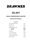
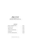
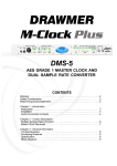
DRAWMER
DS101
NOISE GATE
FOR THE
500 SERIES RACK SYSTEM
CONTENTS
Warranty . . . . . . . . . . . . . . . . . . . . . . . . . . . 2
Safety Consideration . . . . . . . . . . . . . . . . . . 2
Radio Frequencies Statement . . . . . . . . . . . 2
Chapter 1 - Introduction
Introduction . . . . . . . . . . . . . . . . . . . . . . . . 3
Installation . . . . . . . . . . . . . . . . . . . . . . . . . 4
Audio Connection . . . . . . . . . . . . . . . . . . . 4
Typical Connection Guide . . . . . . . . . . . . . 5
Chapter 2 - Control Description
The Gate Controls . . . . . . . . . . . . . . . . . . . 6
The Key Filters . . . . . . . . . . . . . . . . . . . . . . 8
Quick Start Guide . . . . . . . . . . . . . . . . . . . 9
Noise Gate Operation . . . . . . . . . . . . . . . .10
Chapter 3 - General Information
If a fault develops. . . . . . . . . . . . . . . . . . . . 15
Contacting Drawmer . . . . . . . . . . . . . . . . .15
Specification . . . . . . . . . . . . . . . . . . . . . . . 15
Block Diagram. . . . . . . . . . . . . . . . . . . . . . 16
Session Recall Sheet . . . . . . . . . . . . . . . 17
DRAWMER
COPYRIGHT
This manual is copyrighted © 2012 by Drawmer Electronics Ltd. With all rights reserved. Under copyright
laws, no part of this publication may be reproduced, transmitted, stored in a retrieval system or translated
into any language in any form by any means, mechanical, optical, electronic, recording, or otherwise,
without the written permission of Drawmer Electronics Ltd.
ONE YEAR LIMITED WARRANTY
Drawmer Electronics Ltd., warrants the Drawmer DS101 Noise Gate
to conform substantially to the specifications of this manual for a
period of one year from the original date of purchase when used in
accordance with the specifications detailed in this manual. In the
case of a valid warranty claim, your sole and exclusive remedy and
Drawmer’s entire liability under any theory of liability will be to, at
Drawmer’s discretion, repair or replace the product without charge,
or, if not possible, to refund the purchase price to you. This warranty
is not transferable. It applies only to the original purchaser of the
product.
For warranty service please call your local Drawmer dealer.
Alternatively call Drawmer Electronics Ltd. at +44 (0)1709 527574.
Then ship the defective product, with transportation and insurance
charges pre-paid, to Drawmer Electronics Ltd., Coleman Street,
Parkgate, Rotherham, S62 6EL UK. Write the RA number in large
letters in a prominent position on the shipping box. Enclose your
name, address, telephone number, copy of the original sales invoice
and a detailed description of the problem. Drawmer will not accept
responsibility for loss or damage during transit.
This warranty is void if the product has been damaged by misuse,
modification, unauthorised repair or installed with other equipment
that proved to be faulty.
THIS WARRANTY IS IN LIEU OF ALL WARRANTIES, WHETHER
ORAL OR WRITTEN, EXPRESSED, IMPLIED OR STATUTORY.
DRAWMER MAKES NO OTHER WARRANTY EITHER
EXPRESS OR IMPLIED, INCLUDING, WITHOUT LIMITATION,
ANY IMPLIED WARRANTIES OF MERCHANTABILITY, FITNESS
FOR A PARTICULAR PURPOSE, OR NON-INFRINGEMENT.
PURCHASER’S SOLE AND EXCLUSIVE REMEDY UNDER THIS
WARRANTY SHALL BE REPAIR OR REPLACEMENT AS
SPECIFIED HEREIN.
IN NO EVENT WILL DRAWMER ELECTRONICS LTD. BE LIABLE
FOR ANY DIRECT, INDIRECT, SPECIAL, INCIDENTAL OR
CONSEQUENTIAL DAMAGES RESULTING FROM ANY
DEFECT IN THE PRODUCT, INCLUDING LOST PROFITS,
DAMAGE TO PROPERTY, AND, TO THE EXTENT PERMITTED
BY LAW, DAMAGE FOR PERSONAL INJURY, EVEN IF
DRAWMER HAS BEEN ADVISED OF THE POSSIBILITY OF
SUCH DAMAGES.
Some states and specific countries do not allow the exclusion of
implied warranties or limitations on how long an implied warranty may
last, so the above limitations may not apply to you. This warranty gives
you specific legal rights. You may have additional rights that vary from
state to state, and country to country.
For the USA
FEDERAL COMMUNICATIONS COMMISSION RADIO
FREQUENCY INTERFERENCE STATEMENT
This equipment has been tested and found to comply with the limits
for a Class B digital device, pursuant to Part 15 of the FCC Rules.
These limits are designed to provide reasonable protection against
harmful interference in a residential installation. This equipment
generates, uses and can radiate radio frequency energy and, if not
installed and used in accordance with the instructions, may cause
harmful interference to radio communications. However, there is no
guarantee that interference will not occur in a particular installation.
If this equipment does cause interference to radio or television
reception, which can be determined by turning the equipment off an
on, then the user is encouraged to try to correct the interference by
one or more of the following measures:
Re-orient or relocate the receiving antenna.
Increase the separation between the equipment and the receiver.
Connect the equipment into an outlet on a circuit different from that
to which the receiver is connected.
Consult the dealer or an experienced radio/TV technician for help.
Unauthorised changes or modification to this system can void the
users’ authority to operate this equipment.
This equipment requires shielded interface cables in order to meet
FCC class B limit.
For Canada
CLASS B
NOTICE
This digital apparatus does not exceed the Class B limits for radio
noise emissions set out in the Radio Interference Regulations of the
Canadian Department of Communications.
CLASSE B
AVIS
Cet appareil numérique ne dépasse pas les limites de la classe B au
niveau des émissions de bruits radioélectriques fixés dans le
Règlement des signaux parasites par le ministère Canadien des
Communications.
SAFETY CONSIDERATIONS
CAUTION - SERVICING
DO NOT PERFORM ANY SERVICING. REFER ALL SERVICING TO QUALIFIED SERVICE PERSONNEL.
WARNING
TO REDUCE THE RISK OF FIRE OR ELECTRIC SHOCK DO NOT EXPOSE
THIS EQUIPMENT TO RAIN OR MOISTURE.
WARNING
PLEASE BE SURE TO POWER OFF YOUR 500 SERIES RACK BEFORE INSTALLING OR REMOVING
THIS OR ANY OTHER 500 SERIES MODULE. HOT SWAPPING COULD CAUSE DAMAGE TO THIS OR
OTHER EQUIPMENT.
In the interests of product development, Drawmer reserve the right to modify
or improve specifications of this product at any time, without prior notice.
2
CHAPTER 1
DS101
NOISE GATE FOR THE
500 SERIES RACK SYSTEM
The Industry-Standard High-End Noise-Gate comes to the 500 Series!
The DS101 is the first noise gate designed specifically for the 500 Series rack
system and takes its place alongside the Drawmer family of industry standard
Noise Gates, such as the DS201, DS501 and DS404. Anyone familiar with those
units will immediately be at home with the DS101.
Based on a single-channel of the DS201 the DS101 is a sophisticated noise gate
incorporating a number of features pioneered by Drawmer, which are invaluable to
the sound engineer, such as variable high and lowpass filters for “frequency
conscious gating.” Other features include comprehensive envelope control, attack,
hold, decay, and range, plus a whole host of other features, all adding up to one
amazing processor.
When placed side by side in a 500 series rack two or more gates can be linked
using the new infra red triggering mechanism employed on the DS101. This means
that any number of gates can be linked with each having their own envelope shaping
whilst the trigger pulse passes through unchanged, this opens up a whole world
of “envelope follower” effects limited only by your imagination.
Drawmer DS101 single-channel Noise Gate Features at a Glance:
Fully featured noise gate based on the industry standard DS201.
Takes up a single 500 series slot.
Proprietary Hysteris or “trigger stabilization” to prevent “chatter” around the
threshold.
Fully variable high pass and low pass filters for “frequency conscious” gating.
Comprehensive envelope control, attack, hold, decay, and range.
External triggering via key input or the new IR trigger pulse from another DS101.
“Key Listen” facility.
Extremely fast attack time, to preserve the natural attack of the sound.
Linkable - up to ten units in one rack space.
Drawmer “traffic lighting” metering.
Can be used for “Gating” or “Ducking”.
Low noise design.
3
DS101 - Noise Gate for 500 Series Systems
DRAWMER
INSTALLATION
Congratulations on purchasing your new Drawmer product. In order to protect your
new investment, please take a few moments to fill out the warranty registration
card provided in the box, or alternatively visit our website at www.drawmer.com and
fill out the form online.
Quick and easy to do, registering your audio product is important and helps to
serve as proof of ownership for any future warranty issues.
The DS101 does not function stand alone and requires the power supply and the
audio connectors provided by an API 500 series compatible rack frame (not
included).
Installing the DS101 into a 500 Series compatible rack.
1. Before you install anything be sure to turn off the 500 series rack and unplug it
from the mains supply. The 500 Series have not been designed for ‘hot swapping’
and doing so could damage this and other products within the unit, making any
warranty void.
2. After removing the DS101 from its packaging locate a single free slot per DS101.
Note that if you are installing more than one DS101 locate them in slots adjacent to
each other so that the linking feature can work.
3. Whilst looking down into the 500 series rack ensure that the DS101 card edge
connectors line up with the EDAC type connector of the rack, then gently push the
DS101 in place keeping it as square as possible until it is fully located. Do not use
excessive force!
4. Tighten the two front panel screws.
5. Connect the XLR cables to the rear and power up the rack. The DS101 will power
automatically and should be ready to use.
AUDIO CONNECTIONS
The inputs and outputs found on
the back of the 500 rack are
electronically balanced on
conventionally wired XLRs (pin
1 screen, pin 2 hot, pin 3 cold
and XLR shell is connected to
chassis).
The use of balanced wiring is
recommended.
(Please consult your 500 series
manual for further information).
4
TYPICAL CONNECTION GUIDE
DS101 - Noise Gate for 500 Series Systems
5
CHAPTER 2
DRAWMER
CONTROL DESCRIPTION
The DS101 noise gate incorporates many
impressive features, many pioneered by
Drawmer, which are invaluable to the sound
engineer and not found on conventional noise
gates:
• Variable high-pass and low-pass filters for
‘frequency conscious’ gating, with ‘Key listen’
facility.
• Comprehensive envelope control, attack, hold,
decay and range.
• Ultra-fast response time.
• ‘Traffic light’ display giving clear indication of
gate status as well as Threshold Metering.
• Key input for external triggering.
• Linking. Each DS101 can be linked to another
whilst still retaining independent envelopes.
• Can be used for "Gating" or "Ducking".
• High audio specification.
These features are based on the industry
standard, DS201 Noise Gate manufactured by
Drawmer since 1981.
The Gate Controls
Threshold
Infinite to -62.0dB
Sets the level below which gating starts to take
place. For normal noise removal applications,
it is usual to set the Threshold as low as is
possible without spurious triggering occurring,
so that none of the desired signal is lost. The
meter above clearly shows the threshold level
in response to the actual signal.
Attack
10uS to 1S
Controls the speed that the gate opens. The
fastest Attack time ensures that the gate does
not clip the leading edge of extremely fast
signals.
Hold
2mS to 2 Seconds
Determines the amount of time the gate is held
open after the signal falls below the Threshold.
This helps to prevent spurious re-triggering
when using fast Release times, but is also
instrumental in creating the classic gated reverb
sound which is often applied to drums.
6
Decay
2mS to 4 Seconds.
Once the signal has fallen below the Threshold and the Hold time has expired
Decay determines the rate at which the gate closes.
Range
-80 to 0.0 dB
Sets the amount of attenuation applied to the input signal when the gate is closed,
enabling the gate to be used to remove unwanted signals entirely, or simply to
attenuate signals which are too loud. When Duck mode of operation is enabled,
the Range control sets the level to which the signal will be reduced when open
(triggered).
Traffic Light Meter
A three led meter is used to show the operation of the gate. When red the gate is
closed, when green the gate is open and when yellow the gate is closing after the
signal has dropped below the threshold value (as set by Hold).
Duck Switch
Toggles between normal gating and ducking. In Gate mode a Key signal above the
Threshold will cause the Gate to open. In Duck mode the audio passes unattenuated until the Key signal exceeds the Threshold - mainly used for voice-overs
or the removal of ‘clicks’ and ‘pops’ using an External Key Trigger.
Bypass Switch
With the Bypass switch active the input signal is routed to the output with no
processing taking place.
DS101 - Noise Gate for 500 Series Systems
7
DRAWMER
The Key Filters
Source Switch
Ext/Linked/Internal
With no LED lit the source comes from the ‘Internal’ signal. In the Ext position the gate
responds to the signal dynamics of another, independent signal as plugged in via the
1/4” jack. This jack works in the same way as the ‘Key Input’ jack of the DS201, DS404
or DS501.
Using the innovative optical infra red triggering mechanism linking can be acheived
regardless of the 500 series rack that you use. With the switch ‘Linked’ the signal
trigger of each linked channel is set by the ‘Key Filters’ section and the Threshold of the
adjacent left channel - if this is also linked this continues until the Master DS101 is
reached. Note that only adjacent channels can be linked. The Attack, Hold, Range and
Decay controls, as well as the Duck and Bypass switches remain indepentent. In this
way the triggers are the same but differing envelopes can be used for each channel.
Using External Keys
An external audio source may be used to control the Gate action, making it possible to
Gate one channel’s sound according to the dynamics of another independent signal.
For example, gating a bass guitar from a kick drum, or where a brass section can be
keyed from the most experienced player; producing a tighter, more aligned sound.
L.F.
22Hz to 3kHz
The Low Frequency control works
by attenuating frequencies below
the cut-off frequency selected.
H.F.
25Hz to 30kHz
The High Frequency control
attenuates frequencies above the
selected cut-off value.
In other words, when both filters are set, it is the range between the two settings that is
allowed to pass and is the source used to trigger the gate. The optimum use of these
controls is to momentarily operate the channel in Key Listen, and tune-into the loudest
part of the trigger source sound.
8
Key Listen Switch
In normal operation, the filter only affects the way the Gate responds (opens) to the
incoming programme material - it does not have any direct effect on the output
signal, but when Key listen is enabled the effect of the key filter on the programme
material is heard at the output - the audio signal is not routed through gate. Normally
this is used to monitor the effect of the filter to assist in tuning into the specific key
source sound(s) - though it can be used as a Bracketing Filter making it simple to
remove unwanted frequencies without using the resources that a more complicated
equaliser would utilise.
Set up correctly and you will have removed all the room/vehicle rumble, high
frequency amplifier hiss etc. that any mic may pick up. On a snare drum, this filter
can be very effective in controlling bass drum leak, or, on a bass drum, removing
snare rattle. Acoustic guitar or backing vocals can be
greatly improved allowing you to hear midrange clarity
and stereo separation without the need for any
additional equalization.
Quick Start Guide
Setting of controls can be done very quickly using the
following suggestions:
1. Select the Key trigger source using the Key section.
2. Initially, the LF filter should be set fully anticlockwise,
with HF fully clockwise. This will allow the full audio
spectrum of the Key input programme to be monitored.
Set the Range control fully anticlockwise and the Key
Listen selector switched Out.
3. Set the Attack, Hold. Decay and Range controls. For
a programme with long legato release, then Release
will also need to be long, e.g. Piano with reverb. For
material with much low frequency content, the Attack
will need to be quite slow, unless a ‘click’ is desired.
4. With the Release control set at its midway position,
and with suitable programme material fed into the Gate
module, increase the Threshold level from its
anticlockwise position until the Gate starts to operate.
This will be shown by the activity of the traffic light LED’s,
the threshold meter, and you should also hear the effect
on the output signal, in that pauses in the programme
will now be silent.
5. Adjust the settings: If the Threshold setting is too
high, the Gate will start to cut out wanted pieces of
programme, so adjust it to as low a setting as possible.
If the ends of sounds are being truncated, then a longer
Decay time may help. On the other hand, if unwanted
noise is audible after the wanted sound has ended, a
shorter Decay time may be more appropriate.
DS101 - Noise Gate for 500 Series Systems
9
DRAWMER
Noise Gate Operation
There are circumstances when the programme
material is corrupted such as, in a multi-miked
drum kit setup, some hi-hat will inevitably leak
into the snare microphone, some snare drum into
the kick drum microphone and so on. Equally, on
location, you may experience problems due to
wind or traffic noise or close-by conversation. If
the unwanted noise is different in pitch to the
wanted sound, it is often possible, by using the
Key Listen facility, to use the filters to ‘tune’ in to
the wanted sound while excluding the unwanted.
With signals having a naturally slow or moderate
attack, setting the gate attack time too fast can
cause clicks, particularly if the threshold has to
be set high because of excessive background
noise, especially with the audio signal in lower
frequencies (eg bass guitar, bass drum). With a
high threshold, a low frequency sine wave will
be ignored as the signal starts from its zero level
point, as this wave climbs towards its peak, the
level will suddenly exceed the threshold setting,
at this point a very fast attack rate will switch the
signal through the noise gate with such a steep
(almost vertical) leading edge that the low
frequency sound will have a single high
frequency square wave added to its first cycle, in
other words a ‘click’ will be heard. In cases like
these, start with a fast attack time and moderate
threshold, then gradually lengthen the attack time
until the audible click just disappears when the
gate opens, unless the ‘click’ is being added as
an effect!
Gating Vocals
Ducking
Probably the most common form of Ducking is that used by radio
announcers, whereby the volume of the music being played is dropped,
enabling them to speak over it. In Duck mode the music signal is routed to
the input and the announcer’s microphone signal is the key source ( set
‘Source’ to ‘External’ and plug in the mic signal via the jack).
The Range control is used to set the level to which the music will drop duck
is triggered, and the envelope controls determine the rate at which the level
10
will drop and then recover. It is usual to select a
fairly fast Attack time, with a slow Release time of
a second or so - this will react quickly and then
bring the music level back up slowly and smoothly,
and is hence less disconcerting to the listener
In addition to voice over applications, the Duck function
of the DS101 may also be used to treat a signal where
the peaks are too loud and require attenuating. In this
application, ‘Duck’ and ‘Internal’ (i.e source switch not
selected) modes should be selected, and the ‘Range’
control adjusted to give the desired attenuation to
signals above the ‘Threshold’ setting. In extreme cases,
the ducking action may be used to remove signal peaks
altogether, and by careful use of the filters, it may be
possible to remove a snare drum from a drum mix or
clicks and pops from a recording. This same technique
can be used to reduce the level of other instruments
during a solo.
Ducking Music whilst a
Radio Presenter Talks
DS101 - Noise Gate for 500 Series Systems
11
DRAWMER
Difficult Material To Gate
If noise contamination is serious enough to be evident even during moderately
loud programme material, then simple gating will do little to help. Indeed, the very
fact that the Gate produces silence during pauses can make the noise content of
the programme material even more apparent. In extreme cases restricting the
Range of the Gate to about -15dB will adequately reduce the noise during pauses
but not too dramatically.
Remove Humm from a
Guitar
Where the wanted signal does not occupy the full
audio spectrum the Key filters may also be used to
good effect. Taking the example of the electric guitar,
this produces little below 100Hz or above 3kHz so
setting the Gate to Key Listen mode will enable you
to use the filters to exclude much of the amplifier
hum at the low end and hiss at the top end while
having little effect on the sound of the guitar.
Surprisingly, the same is true of the acoustic guitar;
(even a bright-sounding steel-strung model), and
the filters can be used to reduce the effect of string
squeak or the player’s breathing.
When recording drum kits most engineers encounter
severe problems in achieving good separation
between bass, snare, toms and hi-hat etc. Each
tends to bleed through onto virtually every other
microphone. It is here where the key filters of the
gate come into their own:
Suppose that you're gating a snare drum but the hihat is bleeding through into the snare mic at quite a
high level and opening the gate. Without the Filters,
you can't find a Threshold level where the snare
drum opens the gate and the hi-hat doesn't.
Fortunately, the frequency characteristics of the two
sounds differ quite widely; the snare drum covers a
pretty wide frequency range, while the acoustic
energy of the hi-hat is at frequencies above 5kHz. If
you can prevent the high frequencies from getting
through, only the lower frequencies of the snare will
open the gate. In this case, whilst listening using
the Key Listen mode, all you need do is turn down
12
the high frequency control to 3kHz or so. The object is to remove or reduce the
contribution from the hi-hat whilst retain as much of the snare sound as possible.
It’s likely that the Threshold will have to be re-adjusted, as the level may have to be
quite high, and you will have to be careful not to miss the quieter hits, but the hi-hat
should be gated completely, with no unwanted false triggering.
Gating a Kick Drum
Gating a Snare Drum
Gating Toms
Note: The diagrams shown provide settings that should give a useful
starting point during gating. As all scenarios differ they will need to be
altered to provide perfect gating.
DS101 - Noise Gate for 500 Series Systems
13
DRAWMER
Tighten Vocals and Brass Sections
A clever use of the external triggering via the Key input is making particular parts
start and finish at the same time. Regarding vocals and brass sections performers
may start a fraction early, some end a fraction late. Link the channels and use the
backing vocal/trumpet with the best timing as the trigger for the gate to tighten the
timing up.
14
CHAPTER 3
DS101 GENERAL INFORMATION
IF A FAULT DEVELOPS
For warranty service please call Drawmer Electronics Ltd. or their
nearest authorised service facility, giving full details of the difficulty.
A list of all main dealers can be found on the Drawmer webpages.
On receipt of this information, service or shipping instructions will be
forwarded to you.
No equipment should be returned under the warranty without prior
consent from Drawmer or their authorised representative.
For service claims under the warranty agreement a service Returns
Authorisation (RA) number will be issued.
Write this RA number in large letters in a prominent position on the
shipping box. Enclose your name, address, telephone number, copy of
the original sales invoice and a detailed description of the problem.
Authorised returns should be prepaid and must be insured.
All Drawmer products are packaged in specially designed containers
for protection. If the unit is to be returned, the original container must be
used. If this container is not available, then the equipment should be
packaged in substantial shock-proof material, capable of withstanding
the handling for the transit.
CONTACTING DRAWMER
Drawmer Electronics Ltd., will be pleased to answer all application
questions to enhance your usage of this equipment.
Please address correspondence to:
Drawmer (Technical Help line)
Coleman Street
Parkgate
Rotherham
S62 6EL
UK
Alternatively contact us by E-mail on :
[email protected]
Further information on all Drawmer dealers, Authorised service
departments and other contact information can be obtained from our
web pages on:
http://www.drawmer.com
DS101 - Noise Gate for 500 Series Systems
15
DRAWMER
BLOCK DIAGRAM
Ref:1v01 A 20-12-12
16
DS101 - Noise Gate for 500 Series Systems
17