1
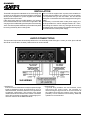
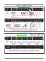
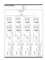
DRAWMER
ACTIVE MIC/LINE
SIGNAL SPLIT TER
CONTENTS
Warranty . . . . . . . . . . . . . . . . . . . . . . . . . . . . . . . . . . . . . . . . . . . . . . . . . . . . . . . . . . . 2
Safety Consideration . . . . . . . . . . . . . . . . . . . . . . . . . . . . . . . . . . . . . . . . . . . . . . . . . 2
Radio Frequencies Statement . . . . . . . . . . . . . . . . . . . . . . . . . . . . . . . . . . . . . . . . . 2
Chapter 1 - Introduction
Introduction . . . . . . . . . . . . . . . . . . . . . . . . . . . . . . . . . . . . . . . . . . . . . . . . . . . . . . . . 3
Installation . . . . . . . . . . . . . . . . . . . . . . . . . . . . . . . . . . . . . . . . . . . . . . . . . . . . . . . . 4
Audio Connection . . . . . . . . . . . . . . . . . . . . . . . . . . . . . . . . . . . . . . . . . . . . . . . . . . 4
Typical Connection Guide . . . . . . . . . . . . . . . . . . . . . . . . . . . . . . . . . . . . . . . . . . . 5
Chapter 2 - Control Description
Inputs . . . . . . . . . . . . . . . . . . . . . . . . . . . . . . . . . . . . . . . . . . . . . . . . . . . . . . . . . . . . . 6
Linking/Outputs/Headphones. . . . . . . . . . . . . . . . . . . . . . . . . . . . . . . . . . . . . . . . . . 7
Chapter 3 - General Information
If a fault develops . . . . . . . . . . . . . . . . . . . . . . . . . . . . . . . . . . . . . . . . . . . . . . . . . . 8
Contacting Drawmer . . . . . . . . . . . . . . . . . . . . . . . . . . . . . . . . . . . . . . . . . . . . . . . . 8
Specification . . . . . . . . . . . . . . . . . . . . . . . . . . . . . . . . . . . . . . . . . . . . . . . . . . . . . . 8
Block Diagram . . . . . . . . . . . . . . . . . . . . . . . . . . . . . . . . . . . . . . . . . . . . . . . . . . . . . 9
Session Recall Sheet. . . . . . . . . . . . . . . . . . . . . . . . . . . . . . . . . . . . . . . . . . . . . . . 11
DRAWMER
COPYRIGHT
This manual is copyrighted © 2010 by Drawmer Electronics Ltd. With all rights reserved. Under copyright laws, no part of this publication may
be reproduced, transmitted, stored in a retrieval system or translated into any language in any form by any means, mechanical, optical,
electronic, recording, or otherwise, without the written permission of Drawmer Electronics Ltd.
ONE YEAR LIMITED WARRANTY
Drawmer Electronics Ltd., warrants the Drawmer 4X4R, Active Signal Splitter to
conform substantially to the specifications of this manual for a period of one
year from the original date of purchase when used in accordance with the
specifications detailed in this manual. In the case of a valid warranty claim, your
sole and exclusive remedy and Drawmer’s entire liability under any theory of
liability will be to, at Drawmer’s discretion, repair or replace the product without
charge, or, if not possible, to refund the purchase price to you. This warranty is
not transferable. It applies only to the original purchaser of the product.
For warranty service please call your local Drawmer dealer. Alternatively call
Drawmer Electronics Ltd. at +44 (0)1709 527574. Then ship the defective product,
with transportation and insurance charges pre-paid, to Drawmer Electronics Ltd.,
Coleman Street, Parkgate, Rotherham, S62 6EL UK. Write the RA number in
large letters in a prominent position on the shipping box. Enclose your name,
address, telephone number, copy of the original sales invoice and a detailed
description of the problem. Drawmer will not accept responsibility for loss or
damage during transit.
This warranty is void if the product has been damaged by misuse, modification
or unauthorised repair.
THIS WARRANTY IS IN LIEU OF ALL WARRANTIES, WHETHER ORAL OR
WRITTEN, EXPRESSED, IMPLIED OR STATUTORY. DRAWMER MAKES NO
OTHER WARRANTY EITHER EXPRESS OR IMPLIED, INCLUDING, WITHOUT
LIMITATION, ANY IMPLIED WARRANTIES OF MERCHANTABILITY, FITNESS
FOR A PARTICULAR PURPOSE, OR NON-INFRINGEMENT. PURCHASER’S
SOLE AND EXCLUSIVE REMEDY UNDER THIS WARRANTY SHALL BE REPAIR
OR REPLACEMENT AS SPECIFIED HEREIN.
IN NO EVENT WILL DRAWMER ELECTRONICS LTD. BE LIABLE FOR ANY
DIRECT, INDIRECT, SPECIAL, INCIDENTAL OR CONSEQUENTIAL DAMAGES
RESULTING FROM ANY DEFECT IN THE PRODUCT, INCLUDING LOST
PROFITS, DAMAGE TO PROPERTY, AND, TO THE EXTENT PERMITTED BY
LAW, DAMAGE FOR PERSONAL INJURY, EVEN IF DRAWMER HAS BEEN
ADVISED OF THE POSSIBILITY OF SUCH DAMAGES.
DRA
WMER
DRAWMER
4X4R
PORTABLE ACTIVE SIGNAL SPLITTER
SAFETY CONSIDERATIONS
CAUTION - MAINS FUSE
TO REDUCE THE RISK OF FIRE REPLACE
THE MAINS FUSE ONLY WITH A FUSE THAT
CONFORMS TO IEC127-2. 250 VOLT
WORKING, TIME DELAY TYPE AND
BODY SIZE OF 20mm x 5mm.
THE MAINS INPUT FUSE MUST BE
RATED AT T500mA.
TO REPLACE A FUSE: WITH THE MAINS CABLE
REMOVED OPEN THE DRAW ON THE I.E.C.
CONNECTOR (arrowed) AND SWAP THE
FUSES. THEN CLOSE THE DRAWER.
Some states and specific countries do not allow the exclusion of implied warranties
or limitations on how long an implied warranty may last, so the above limitations
may not apply to you. This warranty gives you specific legal rights. You may
have additional rights that vary from state to state, and country to country.
For the USA
FEDERAL COMMUNICATIONS COMMISSION RADIO
FREQUENCY INTERFERENCE STATEMENT
This equipment has been tested and found to comply with the limits for a Class
B digital device, pursuant to Part 15 of the FCC Rules. These limits are designed
to provide reasonable protection against harmful interference in a residential
installation. This equipment generates, uses and can radiate radio frequency
energy and, if not installed and used in accordance with the instructions, may
cause harmful interference to radio communications. However, there is no
guarantee that interference will not occur in a particular installation. If this
equipment does cause interference to radio or television reception, which can be
determined by turning the equipment off an on, then the user is encouraged to
try to correct the interference by one or more of the following measures:
Re-orient or relocate the receiving antenna.
Increase the separation between the equipment and the receiver.
Connect the equipment into an outlet on a circuit different from
that to which the receiver is connected.
CAUTION - MAINS CABLE
DO NOT ATTEMPT TO CHANGE
OR TAMPER WITH THE
SUPPLIED MAINS CABLE.
CAUTION - SERVICING
DO NOT PERFORM ANY SERVICING.
REFER ALL SERVICING TO QUALIFIED
SERVICE PERSONNEL.
Consult the dealer or an experienced radio/TV
technician for help.
Unauthorised changes or modification to this system can void the users’ authority
to operate this equipment.
This equipment requires shielded interface cables in order to meet FCC class B
limit.
For Canada
CLASS B
NOTICE
This digital apparatus does not exceed the Class B limits for radio noise emissions
set out in the Radio Interference Regulations of the Canadian Department of
Communications.
WARNING
TO REDUCE THE RISK OF FIRE OR
ELECTRIC SHOCK DO NOT EXPOSE
THIS EQUIPMENT TO RAIN OR MOISTURE.
CLASSE B
AVIS
Cet appareil numérique ne dépasse pas les limites de la classe B au niveau des
émissions de bruits radioélectriques fixés dans le Règlement des signaux parasites
par le ministère Canadien des Communications.
In the interests of product development, Drawmer reserve the right to modify or
improve specifications of this product at any time, without prior notice.
2
CHAPTER 1
DRAWMER
ACTIVE MIC/LINE
SIGNAL SPLIT TER
INTRODUCTION
The 4X4R is a 4 in/16 out mic/line signal splitter. Its extremely high audio quality, and robust build
make it the ideal tool to provide multiple outputs for live sound, broadcast coverage, sports events,
live recording, press conferences, corporate events and any situation where distribution of high quality
audio is required. It incorporates 4 studio grade mic/line pre-amps, each providing up to 66dB of gain
and 16 balanced output stages, each with the option of transformer isolation and comprehensive
linking facilities.
INPUTS:
4 STUDIO GRADE MIC/LINE PRE-AMPS
INDEPENDENT INPUT BARGRAPH METERING
66dB OF VARIABLE GAIN
48V PHANTOM POWER
MIC/LINE SWITCHING
HEADPHONE MONITORING FACILITY
OUTPUTS:
4 OUTPUTS PER CHANNEL
OPTIONAL TRANSFORMER ISOLATION
TRANSFORMER LOADED LED STATUS
LINKING
CAN BE CONFIGURED AS:
1x 1 IN/16 OUT
2x 1 IN/ 8 OUT
1x 1 IN/12 OUT plus 1 IN/4 OUT
4x 1 IN/4 OUT
3
DRAWMER
INSTALLATION
The4X4R is designed for standard 19" rack mounting and
occupies 1U of rack space. Avoid mounting the unit directly
above power amplifiers or power supplies that radiate
significant amounts of heat.
If the unit is to be used in a mobile situation, it is strongly
recommended that the rear of the unit is supported in the
carrying rack to avoid bending the front panel rack mounting
‘ears’. Use fibre or plastic washers to prevent the front panel
becoming marked by the mounting bolts.
The unit will be supplied with a power cable suitable for
domestic power outlets in your country. For your own safety
it is important that you use this cable. The unit should
always be connected to the mains supply earth using this
cable.
Powered by a universal switch mode power supply, the
4X4R operates from mains voltages between 85 - 250v,
eliminating the need to make any changes when touring
and allowing the unit to remain fully operational during large
fluctuations in the mains power supply.
AUDIO CONNECTIONS
The inputs and outputs are electronically balanced on conventionally wired XLRs (pin 1 screen, pin 2 hot, pin 3 cold and
XLR shell is connected to chassis). Balanced use is recommended.
XLR WIRING
• Interference:
If the unit is to be used where it maybe exposed to high
levels of disturbance such as found close to a TV or
radio transmitter, we advise that the unit is operated in
a balanced configuration. The screens of the signal
cables should be connected to the chassis connection
on the XLR connector as opposed to connecting to pin1.
The 4X4 conforms to the EMC standards.
4
• Ground Loops:
If ground loop problems are encountered, never
disconnect the mains earth, but instead, try
disconnecting the signal screen on one end of each of
the cables connecting the outputs of the 4X4 to the
patchbay. If such measures are necessary, balanced
operation is recommended.
TYPICAL CONNECTION GUIDE
FOR OUTSIDE BROADCAST
Each of the four inputs has its own set of four outputs - to simultaneously send to Front
of House, Monitor Console, Recording and Outside Broadcast, for example.
FOR PRESS CONFERENCES
With all the link switches active, one input can be sent to all sixteen outputs - to be used in a
press conference, for instance, so that all parties can have a direct feed. In such cases the output
level, +48v, mic/line etc. is controlled by the CH1 parameters.
5
DRAWMER
CHAPTER 2
CONTROL DESCRIPTION
The control layout of the Drawmer 4X4R comprises of the mains inlet, headphone monitoring section, and four identical preamplifier and splitter channels - the only difference being the link switches. Each of the four channels is based around
Drawmer's own discrete component mic preamp, which delivers very low distortion and a wide dynamic range, providing upto
66dB of switchable gain, mic/line selection and phantom power, as well as four outputs, either electronic or transformer
isolated (factory fitted optional extra).
The location of components has been carefully considered in order to be very intuative and also to make cable routing as clean
and unobtrusive as possible. When fully loaded the 4X4 will have a total of twenty XLR cables, a headphone cable and also the
mains - with four of the XLR outputs conveniently located on the front panel for easier access.
Each of the four channels are (almost) identical, with the controls for each as follows:
Inputs
1 MIC/LINE
Switches the level of input 4 between Mic or Line, with LED indication. When in the 'Line' position
the phantom power switch is bypassed, the input has a 20dB pad, and the input impedance alters
to >10k Ohms.
2 PHANTOM POWER A switch provides +48V Phantom Power down the XLR cable to microphones that require it.
NOTE: DO NOT ACTIVATE THE +48V SWITCH UNLESS YOU ARE SURE THAT THE MICROPHONE
REQUIRES IT.
3 GAIN
A twelve position switch adds gain in 6dB steps from 0dB to +66dB, to have total control over levels
and make it incredibly easy to replicate.
4 V.U. METER
Each channel has an six LED VU meter, covering the range from -20dB to +18dB.
5 LISTEN
Activating the switch will route the input from that particular channel to the headphone section for
monitoring. Each channel can be active seperately (solo) or all can be monitored at once if preferred.
(SEE HEADPHONES).
6
Linking
6 LINK
In certain situations four outputs may not be adequate, for example at a news conference where each
reporter requires a feed, for this reason we have incorporated a very versatile, but intuitive linking system,
that effectively converts the 4X4 into a pressbox. Linking is via three switches, so there’s no need to open the
unit up to swap jumpers, or worse still, re-solder connections. If a link switch is active the input feeding the
four outputs of that particular channel is disabled, and re-routed to the input of the previous channel. If the
link switch of that channel is also active, then it is re-routed further to the previous channel. In this way any
combination of linking can be available -
4x 1 input /4 outputs
1x 1 in /8out & 2x 1in/4out
2x 1 input /8outputs
1x 1 in /8out & 2x 1in/4out
1x 1 in /12out & 1x 1in/4out
1x 1 input /16outputs
8
Headphones
A single 1/4” TRS jack socket 7 with fully adjustable level control 8 has been incorporated to provide headphone monitoring.
To determine which input is monitored see LISTEN 5 .
Caution should be used when using high output levels and low impedance headphones.
DRAWMER do NOT accept any responsibility for damage caused to the operator’s hearing or speaker
devices by the use of excessive output levels.
Inputs
9 INPUT
The input is via a standard XLR for both mic and line input - pin one is screen, pin two is positive
(hot) and pin three negative (cold).
Outputs
Each input of the four channels is split (duplicated) into four seperate outputs either electronically or using Transformer
Isolation (a factory fitted optional extra).
Transformer isolation is the best way to remove ground loops that cause hum and buzz (by decoupling the ground ), RF
interference (by improving the "balanced" characteristic of the line (called "Common Mode Rejection" or CMR)), or to isolate
mixing consoles so that the levels of one does not effect the other down the cables within the audio system.
An inherant problem with a direct splitter is that overall input impedance is reduced, which in critical high quality applications
can degrade frequency response, particularly on long cables, such as those used in outside recording and broadcast, and
add unwanted interference. The combination of adding gain via the preamplifier and transformer isolation improves this
dramatically, allowing for longer cable lengths and clearer more defined recordings.
10a 10b 10c
OUTPUTS
10d
Each channel has four outputs, via standard XLR connectors (pin one is screen, pin two is positive
(hot) and pin three negative (cold)) three of which are located on the rear panel adjacent to the input,
and one, for each channel, is located on the front panel.
7
DRAWMER
CHAPTER 3
4X4R GENERAL INFORMATION
IF A FAULT DEVELOPS
For warranty service please call Drawmer Electronics Ltd. or
their nearest authorised service facility, giving full details of
the difficulty.
SPECIFICATION
INPUT IMPEDANCE
Input Impedance
Maximum Input Level
A list of all main dealers can be found on the Drawmer
webpages.
OUTPUT
On receipt of this information, service or shipping instructions
will be forwarded to you.
Output Impedance
Maximum Output Level
No equipment should be returned under the warranty without
prior consent from Drawmer or their authorised representative.
BANDWIDTH
For service claims under the warranty agreement a service
Returns Authorisation (RA) number will be issued.
Write this RA number in large letters in a prominent position
on the shipping box. Enclose your name, address, telephone
number, copy of the original sales invoice and a detailed
description of the problem.
Authorised returns should be prepaid and must be insured.
All Drawmer products are packaged in specially designed
containers for protection. If the unit is to be returned, the original
container must be used. If this container is not available, then
the equipment should be packaged in substantial shock-proof
material, capable of withstanding the handling for the transit.
Drawmer Electronics Ltd., will be pleased to answer all
application questions to enhance your usage of this
equipment. Please address correspondence to:
Drawmer (Technical Help line)
Coleman Street
Parkgate
Rotherham
S62 6EL
UK
Alternatively contact us by E-mail on :
[email protected]
Further information on all Drawmer dealers, Authorised service
departments and other contact information can be obtained
from our web pages on:
http://www.drawmer.com
8
50 Ohms
+21dBu
<13.4Hz to 46kHz -1dB
<8Hz to 85kHz -3dB
MIC EIN
Ref 150R, 0dB
Audio Band
-128dBu
Distortion THD
Line Input @+4dB
0.005%
LINE NOISE
Ref +4dB
-100dBu
-93dBu
Audio Band
Full Band
CROSSTALK
between adjacent
channels
CONTACTING DRAWMER
mic: 1k Ohms
line: 4.1k Ohms
+21dBu
better than 87dB @ 20kHz
POWER REQUIREMENTS
115V or 230V at 50-60Hz, 20VA
FUSE RATING T500mA for both 115V and 230V,
Conforming to IEC 127-2
FUSE TYPE
20mm x 5mm, Class 3 Slo-Blo,
250Volt working
CASE SIZE
482mm(W) x 44mm(H) x 223mm(D)
WEIGHT
w/o isolating transformers 2.8kg
with isolating transformers 3.3kg
BLOCK DIAGRAM
Ref:1v01 A 12-06-08
9
DRAWMER
10
11