1
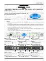
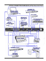
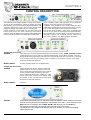
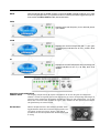
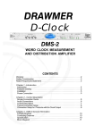
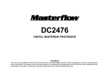
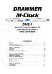
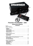
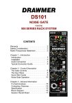
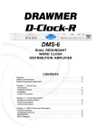
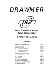
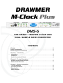
DRAWMER
M-Clock Plus
DMS-5
AES GRADE 1 MASTER CLOCK AND
DUAL SAMPLE RATE CONVERTER
CONTENTS
Warranty . . . . . . . . . . . . . . . . . . . . . . . . . . . . . . . . . . . . . . . . . . . . . . . . . . . . . . . . . . . 2
Safety Consideration . . . . . . . . . . . . . . . . . . . . . . . . . . . . . . . . . . . . . . . . . . . . . . . . . 2
Radio Frequencies Statement . . . . . . . . . . . . . . . . . . . . . . . . . . . . . . . . . . . . . . . . . 2
Chapter 1 - Introduction
Introduction . . . . . . . . . . . . . . . . . . . . . . . . . . . . . . . . . . . . . . . . . . . . . . . . . . . . . . . . 3
Installation . . . . . . . . . . . . . . . . . . . . . . . . . . . . . . . . . . . . . . . . . . . . . . . . . . . . . . . . 4
Audio Connection & Guide . . . . . . . . . . . . . . . . . . . . . . . . . . . . . . . . . . . . . . . . . . . 4
Chapter 2 - Control Description
Multiple Sample Rate Converter . . . . . . . . . . . . . . . . . . . . . . . . . . . . . . . . . . . . . . 6
Master Clock Generator . . . . . . . . . . . . . . . . . . . . . . . . . . . . . . . . . . . . . . . . . . . . . 7
Chapter 3 - General Information
If a fault develops . . . . . . . . . . . . . . . . . . . . . . . . . . . . . . . . . . . . . . . . . . . . . . . . . . 8
Contacting Drawmer . . . . . . . . . . . . . . . . . . . . . . . . . . . . . . . . . . . . . . . . . . . . . . . . 8
Specification . . . . . . . . . . . . . . . . . . . . . . . . . . . . . . . . . . . . . . . . . . . . . . . . . . . . . . 8
Block Diagram . . . . . . . . . . . . . . . . . . . . . . . . . . . . . . . . . . . . . . . . . . . . . . . . . . . . . 9
COPYRIGHT
This manual is copyrighted © 2008 by Drawmer Electronics Ltd. With all rights reserved. Under copyright laws, no part of this publication may
be reproduced, transmitted, stored in a retrieval system or translated into any language in any form by any means, mechanical, optical,
electronic, recording, or otherwise, without the written permission of Drawmer Electronics Ltd.
ONE YEAR LIMITED WARRANTY
Drawmer Electronics Ltd., warrants the Drawmer DMS-5 M-Clock Plus, AES
Grade 1 Master Clock and Dual Sample Rate Converter to conform substantially
to the specifications of this manual for a period of one year from the original date
of purchase when used in accordance with the specifications detailed in this
manual. In the case of a valid warranty claim, your sole and exclusive remedy
and Drawmer’s entire liability under any theory of liability will be to, at Drawmer’s
discretion, repair or replace the product without charge, or, if not possible, to
refund the purchase price to you. This warranty is not transferable. It applies
only to the original purchaser of the product.
For warranty service please call your local Drawmer dealer. Alternatively call
Drawmer Electronics Ltd. at +44 (0)1709 527574. Then ship the defective product,
with transportation and insurance charges pre-paid, to Drawmer Electronics Ltd.,
Coleman Street, Parkgate, Rotherham, S62 6EL UK. Write the RA number in
large letters in a prominent position on the shipping box. Enclose your name,
address, telephone number, copy of the original sales invoice and a detailed
description of the problem. Drawmer will not accept responsibility for loss or
damage during transit.
This warranty is void if the product has been damaged by misuse, modification
or unauthorised repair.
THIS WARRANTY IS IN LIEU OF ALL WARRANTIES, WHETHER ORAL OR
WRITTEN, EXPRESSED, IMPLIED OR STATUTORY. DRAWMER MAKES NO
OTHER WARRANTY EITHER EXPRESS OR IMPLIED, INCLUDING, WITHOUT
LIMITATION, ANY IMPLIED WARRANTIES OF MERCHANTABILITY, FITNESS
FOR A PARTICULAR PURPOSE, OR NON-INFRINGEMENT. PURCHASER’S
SOLE AND EXCLUSIVE REMEDY UNDER THIS WARRANTY SHALL BE REPAIR
OR REPLACEMENT AS SPECIFIED HEREIN.
IN NO EVENT WILL DRAWMER ELECTRONICS LTD. BE LIABLE FOR ANY
DIRECT, INDIRECT, SPECIAL, INCIDENTAL OR CONSEQUENTIAL DAMAGES
RESULTING FROM ANY DEFECT IN THE PRODUCT, INCLUDING LOST
PROFITS, DAMAGE TO PROPERTY, AND, TO THE EXTENT PERMITTED BY
LAW, DAMAGE FOR PERSONAL INJURY, EVEN IF DRAWMER HAS BEEN
ADVISED OF THE POSSIBILITY OF SUCH DAMAGES.
Some states and specific countries do not allow the exclusion of implied warranties
or limitations on how long an implied warranty may last, so the above limitations
may not apply to you. This warranty gives you specific legal rights. You may
have additional rights that vary from state to state, and country to country.
DRA
WMER
DRAWMER
M-Clock Plus
DMS-5
AES GRADE 1 MASTER
CLOCK AND DUAL SAMPLE
RATE CONVERTER
SAFETY CONSIDERATIONS
CAUTION - MAINS FUSE
TO REDUCE THE RISK OF FIRE
REPLACE THE MAINS FUSE ONLY WITH
A FUSE THAT CONFORMS TO IEC127-2.
250 VOLT WORKING, TIME DELAY TYPE
AND BODY SIZE OF 20mm x 5mm.
THE MAINS INPUT FUSE MUST BE
RATED AT T315mA.
For the USA
FEDERAL COMMUNICATIONS COMMISSION RADIO
FREQUENCY INTERFERENCE STATEMENT
This equipment has been tested and found to comply with the limits for a Class
B digital device, pursuant to Part 15 of the FCC Rules. These limits are designed
to provide reasonable protection against harmful interference in a residential
installation. This equipment generates, uses and can radiate radio frequency
energy and, if not installed and used in accordance with the instructions, may
cause harmful interference to radio communications. However, there is no
guarantee that interference will not occur in a particular installation. If this
equipment does cause interference to radio or television reception, which can be
determined by turning the equipment off an on, then the user is encouraged to
try to correct the interference by one or more of the following measures:
Re-orient or relocate the receiving antenna.
Increase the separation between the equipment and the receiver.
Connect the equipment into an outlet on a circuit different from
that to which the receiver is connected.
Consult the dealer or an experienced radio/TV
technician for help.
Unauthorised changes or modification to this system can void the users’ authority
to operate this equipment.
This equipment requires shielded interface cables in order to meet FCC class B
limit.
For Canada
CAUTION - MAINS CABLE
DO NOT ATTEMPT TO CHANGE
OR TAMPER WITH THE
SUPPLIED MAINS CABLE.
CAUTION - SERVICING
DO NOT PERFORM ANY SERVICING.
REFER ALL SERVICING TO QUALIFIED
SERVICE PERSONNEL.
WARNING
TO REDUCE THE RISK OF FIRE OR
ELECTRIC SHOCK DO NOT EXPOSE
THIS EQUIPMENT TO RAIN OR MOISTURE.
CLASS B
NOTICE
This digital apparatus does not exceed the Class B limits for radio noise emissions
set out in the Radio Interference Regulations of the Canadian Department of
Communications.
CLASSE B
AVIS
Cet appareil numérique ne dépasse pas les limites de la classe B au niveau des
émissions de bruits radioélectriques fixés dans le Règlement des signaux parasites
par le ministère Canadien des Communications.
In the interests of product development, Drawmer reserve the right to modify or
improve specifications of this product at any time, without prior notice.
2
CHAPTER 1
DRAWMER
M-Cloc
k Plus
M-Clock
DMS-5
AES GRADE 1 MASTER CLOCK AND DUAL SAMPLE RATE CONVERTER
INTRODUCTION
The M-Clock Plus is a high stability master clock generator offering
clock rates from 44.1 to 192kHz, coupled to two sample rate
converters, which allow material to be re-sampled and syncronised
to the selected high precision clock.
In addition to the internal clocks, M-Clock Plus can sync to either
external word clock or clocks from AES/EBU signals. Precision
clock frequency measurement and display indicates the exact
frequency of the selected clock, whether internal or external, to an
accuracy of 2ppm.
Features:
M-Clock Plus has an external word clock input and an AES11 input which retrieves the clock from an AES
audio signal.
Each sample rate converter has selectable AES, SPDIF or TOSLINK inputs, with simultaneous AES, SPDIF
and TOSLINK outputs. This allows many possibilities for format conversion as well as sample rate conversion.
Sample rate converter #2 has inputs on the front panel for easy access.
User selectable word length of 16 or 24 bits with automatic dither generation - particularly valuable for 16 bit
word lengths at low signal levels.
10 word clock outputs - 8 at the rear and 2 at the front for easy access.
1
2
3
4
1 S.R.C.1 Inputs:
5
6
7
2 S.R.C.1 Source:
One each of S/PDIF, TOSLINK or AES
conveniently located for easy access.
4 S.R.C.2 Source:
7 Display Mode:
6
15
10 S.R.C.1 Outputs:
One each of S/PDIF, TOSLINK or AES
symultaneous outputs.
13 Wordclock Inputs:
Inputs in both standard wordclock
(BNC) and AES 11 (XLR) upto 192kHz.
13
Blue/White liquid crystal display with three
switchable modes of operation.
9 Wordclock Outputs 9/10:
Output sample rate selector with switch
for EXT source also 13 .
14
Switch to select S.R.C.1 Word Length of
16 or 24 Bit.
6 Display:
Switch to select S.R.C.1 Word Length of
16 or 24 Bit.
8 Master Clock Generator:
Switch to control the Mode of Display
from FREQ. +/-PPM or +/-%.
9
3 S.R.C.1 Word Length:
Switch to select one of the three the
S.R.C.1 Input Sources 1 . With lock led.
5 S.R.C.2 Word Length:
Switch to select one of the three the
S.R.C.2 Input Sources 11 . With lock led.
8
12
11 S.R.C.2 Inputs:
One each of S/PDIF, TOSLINK or AES
selected via 4 .
Two extra wordclock outputs
conveniently placed for easy access.
11
10
12 S.R.C.2 Outputs:
One each of S/PDIF, TOSLINK or AES
symultaneous outputs.
14 4x AES 11 XLR & SPDIF Outputs: 15 8x BMC Clock Outputs:
outputs to the AES 11 standard
(Also called DARS, Blank Frame).
Buffered BNC wordclock outputs with
33 Ohms impedance.
3
INSTALLATION
The DMS-5 is designed for standard 19" rack mounting
and occupies 1U of rack space. Avoid mounting the unit
directly above power amplifiers or power supplies that
radiate significant amounts of heat.
If the unit is to be used in a mobile situation, it is strongly
recommended that the rear of the unit is supported in the
carrying rack to avoid bending the front panel rack mounting
‘ears’. Use fibre or plastic washers to prevent the front panel
becoming marked by the mounting bolts.
The unit will be supplied with a power cable suitable for
domestic power outlets in your country. For your own safety
it is important that you use this cable. The unit should
always be connected to the mains supply earth using this
cable.
Powered by a universal switch mode power supply, the
DMS-5 M-Clock Plus operates from mains voltages between 85 - 250v, eliminating the need to make any changes
when touring and allowing the unit to remain fully operational during large fluctuations in the mains power supply.
AUDIO CONNECTIONS
AES11
Is via an XLR connector designed to be used with standard
balanced microphone cable (20 metres maximum), wired
pin 1 screen, pin 2 and 3 balanced data, and the XLR shell
connected to the chassis. Having many short cables joined
together is not advisable as each connector can cause
undesirable signal reflections.
The output socket fully conforms to the EMC standards; if
the unit is to be used where it may be exposed to high
levels of disturbance, such as found close to a TV or radio
transmitter, it is suggested that the screen of the data cable
be connected to the chassis connection on the XLR type
connector rather than to pin 1.
If ground loop problems are encountered, never disconnect
the mains ground, but instead, try disconnecting the signal
screen on one end of each cable connecting the outputs.
S/PDIF
Is via a high quality RCA type phono jack where the data
conforms to the SonyJ PhillipsJ Digital InterFace format.
Because this connector only provides an unbalanced
termination, the recommended maximum length for this
cable is 3 metres, even with very high quality cable.
TOSLINK (or EIAJ)
The real benefit of TOSlink is that it is not susceptible to
electromagnetic noise, however, it is highly recommended
that a very good quality cable is used as the plastic
conductors used in cheap cables can damage data.
Additionally performance is compromised over long lengths
of cable, as the signal strength weakens due to impurities
in the conductive material, therefore lengths of no longer
than five metres is recommended unless using a signal
booster..
Though the connectors are the same TOSLink and ADAT
Optical are not compatible with each other.
Word Clock
Use only good quality 75Ω digital or video coax (not aerial
downlead) cable for the word-clock signals, terminated with
the correct type of 75Ω BNC connectors - inferior cables
will introduce jitter and will completely undermine the
performance benefits which might be achieved by using a
master clock in the first place!
SIMPLE WORDCLOCK DISTRIBUTION SETUP
4
TYPICAL CONNECTION GUIDE (M-Clock Plus Generates Clock).
5
CHAPTER 2
CONTROL DESCRIPTION
The Drawmer M-Clock Plus supplies ten word clock outputs,
as well as two simultaneous outputs of S/PDIF and AES/
EBU allowing you to synchronize your digital workstation, A/D
converter, digital mixer and a host of other digital audio
equipment through one stable and very accurate unit.
Certain equipment in the studio may not have word clock
inputs which has in the past caused synchronisation
problems, using the DMS-5 M-CLOCK Plus these digital audio
sources may be synched to the same ultra low jitter AES
grade 1 stability master clock generator as the equipment
using the word clock outputs from the DMS-5.
In addition, if any equipment in the studio suffers jitter at its
output these sample rate converters may be used to de-jitter
and re-clock the signals before further transmission.
The M-clock Plus provides a wide range of sample rates
from 44.1k upto 192k, all set using the front panel switching.
Each sample rate converter input is fed simultaneously to
AES/EBU, SPDIF and TOSLINK outputs solving any
connectivity problems and allowing signal distribution.
Sample Rate Converter 1
SOURCE
Three inputs are conveniently located on the front panel for easy access - SPDIF, TOSLINK and AES.
Toggle through the “Source” switch to select the desired input. A lock LED is provided - when lit a
strong signal is being recieved by that input source and the M-Clock Plus is “locked on”. If the LED
is off the input source may be missing, weak or unstable - in this case the source of the signal
should be located and improved.
WORD LENGTH
A switch provides either 16 or 24 Bit operation.
Sample Rate Converter 2
SOURCE
Toggle through the “Source” switch to select the
desired input on the S.R.C.2 outputs on the rear
panel. A lock LED is provided on the front - when lit
a strong signal is being recieved by that input
source and the M-Clock Plus is “locked on”. If the
LED is off the input source may be missing, weak
or unstable - in this case the source of the signal
should be located and improved.
WORD LENGTH
As above.
DISPLAY
A Blue/White LCD display wth four switchable modes of operation: When reading from it’s own
internal clock the M-Clock Plus will display a sample rate of 44.1kHz. , when reading from an
EXTernal source it displays either FREQ, ±PPM or ±% depending on the mode set.
The mode that is selected during power down is saved for the next session.
The display accuracy is 2ppm at all sample rates up to 192kHz, or 0.1Hz increments @
48KHz sample rate.
6
MODE
With the sample rate set to EXT a switch controls the mode of display enabling you to read
the incoming sample rate in your preferred manner. Pressing the switch toggles through the
three modes of FREQ, ±PPM and ±%, with led indication.
FREQ
Displays the actual frequency to four decimal places
upto 192kHz.
±PPM
Displays the nominal sample rate with +/- ppm (part
per million) error indication for 32, 44.1, 48, 88.2, 96 &
192KHz.
±%
Displays the nominal sample rate with percentage pull
up/down indication for 32, 44.1, 48, 88.2, 88.2, 96 &
192KHz
MASTER CLOCK GENERATOR
SAMPLE RATE
The outgoing sample rate for all outputs of the DMS-5 can be set using the two sample rate
switches - the left moving down rate and the right moving up, with a corresponding LED being lit to
show the current sample rate. The DSM-5 generates six Ultra Low Jitter sample rates - 44.1k, 48k,
88.2k, 96k, 176.4k and 192k, all stable to <1ppm, and in addition can also operate at the sample
rate generated by an external source.
EXT SOURCE
With the Sample Rate set to EXT the EXT SOURCE switch
toggles between either AES or Wordclock (as located on the
rear panel). As with the “Source” section a lock LED is
provided on the front and operates when the EXT clock signal
is strong.
7
CHAPTER 3
M-CLOCK Plus DMS-5 GENERAL INFORMATION
IF A FAULT DEVELOPS
For warranty service please call Drawmer Electronics Ltd. or
their nearest authorised service facility, giving full details of
the difficulty.
SPECIFICATION
Internal Clock Generator
2 x Temperature Compensated Xtal Oscillators (TCXOs)
AES11 GRADE 1 Stability,
Tolerance
+/-1ppm (0-60 Celcius),
<<+/-1ppm (15-30
Celcius)
Phase noise
-130 dBc/Hz @ 1kHz
On receipt of this information, service or shipping instructions
will be forwarded to you.
@ 24.5760 MHz to give Fs
48, 96 & 192 kHz
@ 22.5792 MHz to give Fs
44.1, 88.2 & 176.4kHz
No equipment should be returned under the warranty without
prior consent from Drawmer or their authorised representative.
Word Clock Outputs
A list of all main dealers can be found on the Drawmer
webpages.
For service claims under the warranty agreement a service
Returns Authorisation (RA) number will be issued.
Write this RA number in large letters in a prominent position
on the shipping box. Enclose your name, address, telephone
number, copy of the original sales invoice and a detailed
description of the problem.
Authorised returns should be prepaid and must be insured.
All Drawmer products are packaged in specially designed
containers for protection. If the unit is to be returned, the original
container must be used. If this container is not available, then
the equipment should be packaged in substantial shock-proof
material, capable of withstanding the handling for the transit.
Output impedance
33 ohms
All outputs selectable between
44.1, 48, 88.2, 96, 176.4
and 192 kHz
AES 11 Outputs
2 x Neutrik XLR
110 ohm source @ 44.1,
48, 88.2, 96, 176,192kHz
2 x Gold Plated Phono
75 ohm source @ 44.1,
48, 88.2, 96, 176,192kHz
Sample Rate Conversion
2 x Stereo Sample
Rate Converters:
full up/down conversion
from 44.1kHz to 192kHz
2 x Neutrik XLR AES/EBU inputs
2 x Phono SPDIF inputs
2 x TOSlink inputs
CONTACTING DRAWMER
Drawmer Electronics Ltd., will be pleased to answer all
application questions to enhance your usage of this
equipment. Please address correspondence to:
Drawmer (Technical Help line)
Coleman Street
Parkgate
Rotherham
S62 6EL
UK
All outputs simultaneous on
2 x AES/EBU XLR,
2 x SPDIF Phono,
2 x TOSLINK
THD+Noise
> 130 dBFs
Display
Blue/white LCD display wth three switchable modes of
operation with mode led indicators for each:
frequency
actual frequency up to >192KHz
+/- ppm
nominal sample rate with +/- ppm error
indication for 32,44.1,48,88.2, 96 & 192KHz
+/-%
Nominal sample rate with percent pull up/
down indication for 32,44.1,48,88.2, 96 &
192KHz
Accuracy
2ppm at all sample rates up to 192KHz
0.1 Hz increments @ 48KHz sample rate
Alternatively contact us by E-mail on :
[email protected]
Further information on all Drawmer dealers, Authorised service
departments and other contact information can be obtained
from our web pages on:
http://www.drawmer.com
8
General
Power Supply:
Internal, Universal Input, 15 W
Fuse Rating
T315mA for All voltages.
CONFORMING TO: IEC127-2
Fuse Type
20mm x 5mm, Class 3 Slow - Blow
250Volt working
Dimensions:
1u, 19" Rack Mount,
482mm(W) x 44mm(H) x 145mm(D)
Weight
2.025 kg
BLOCK DIAGRAM
Ref:1v01 A 11-02-08
9
10