1
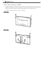
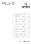
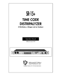
SAMSUNG
Office DECT 8000
Installation and
Programming
Manual
Publication Information
Samsung Telecoms reserves the right without prior notice to revise information in this publication for any reason.
Samsung Telecoms also reserves the right without prior notice to make
changes in design or components of equipment as engineering and manufacturing may warrant.
Disclaimer
Samsung Telecoms is not responsible for errors or problems arising
from customers not installing, programming or operating their Samsung
systems as described in this manual.
Copyright 2001
Samsung Telecoms (U.K.) Limited
All rights reserved. No part of this manual may be reproduced in any
form or by any means – graphic, electronic or mechanical, including
recording, taping, photocopy or information retrieval system – without
express written permission of the publisher of this material.
Part No.:17410
Version 1.0
EU Declaration of Conformity (R&TTE)
Tae Kwang Industrial Co., Ltd
191-1, Anyang-7dong, Manan-gu, Anyang City, Gyunggi-do, Korea
(factory name, address)
declare under our sole responsibility that the product
Digital Keyphone DECT “Office DECT 8000”
To which this declaration relates is in conformity with
R&TTE Directive 1999/5/EC (Annex III)
Low Voltage Directive 73/23/EEC
EMC Directive 89/336/EEC:92/31/EEC
0681
By application of the following standards
CTR6 (July 1997)
EN 301 489-1-6 : 2000
EN 50081-1 : 1993
EN 50082-1 : 1997
EN 60950 : 1997
(Manufacturer)
ACRO Telecom Co., Ltd
5F Hwachon Bldg, 334-1 Yangjaedong
Seochogu, Seoul, Korea
2001 03 20 K H Kim
(place and date of issue)
Kyoung-Hyun Kim / President
(name and signature of authorized person)
(Representative in the EU)
Samsung Telecoms (UK) Ltd
Unit B2, Brookside Business Park,
Greengate, Middleton, Manchester
M24 1GS, United Kingdom
2001 05 28
D Norton
(place and date of issue)
David Norton / Managing Director
(name and signature of authorized person)
For other declarations relevant to DCS and DCS Compact II systems, refer to the Samsung
Telecoms website at: www.samsung-telecoms.co.uk
Intended Use
This DECT telephone handset is intended to communicate with a Samsung telephone system, where such a telephone system is provided with the appropriate DECT interface. It allows the user to make and receive voice calls.
An optional ear-microphone (headset) unit can be connected. The telephone is powered by an integral battery
which is charged through the base unit provided. It should not be used for any other purpose.
i
Contents
Chapter 1 DECT System Overview ................................................................
................................................................ 11-1~11~1-5
What is DECT ? ..............................................................................................................................................
History ..........................................................................................................................
What Standards Define DECT ? .....................................................................................
Specifications for DECT .................................................................................................
DECT Time Slot and Frame Structure ............................................................................
Basic Functions of the DECT System .............................................................................
List of Abbreviations ....................................................................................................................................
1-2
1-2
1-2
1-2
1-3
1-3
1-5
Chapter 2 DECT System Components ..........................................................
.......................................................... 22-1~21~2-4
Base Station Interface (BSI) Card ...........................................................................................................
3BSI Card .....................................................................................................................
4BSI Card .....................................................................................................................
8BSI Card .....................................................................................................................
DECT Base Station (DBS) .............................................................................................................................
2-1
2-1
2-2
2-3
2-4
................................
................ 3Chapter 3 Site Survey with Office DECT 8000................................................
................................
3-1~31~3-10
Considerations ............................................................................................................................................. 3-1
Before Starting the Site Survey .................................................................................................................. 3-3
Site Survey Procedure ................................................................................................................................. 3-4
Checklist for Survey Data ........................................................................................................................... 3-5
Reporting Site Survey Results ........................................................................................ 3-6
Example Cell Planning Results ....................................................................................... 3-8
Chapter 4 Installation ................................................................
.................................................................................
................................................. 44-1~41~4-18
Installation Procedure ................................................................................................................................. 4-1
Installing BSI Card ......................................................................................................................................... 4-2
Installing 3BSI Card in COMPACT II .............................................................................. 4-2
Installing 4BSI and 8BSI Card in DCS ........................................................................... 4-3
Connecting BSI Card and DBS .................................................................................................................. 4-6
Cable Requirements ...................................................................................................... 4-6
Connecting Cable to Compact II ................................................................................... 4-11
Connecting Cable to DCS ............................................................................................. 4-12
Connecting Cable to DBS ............................................................................................. 4-12
Installing DBS .............................................................................................................................................. 4-14
Tools Required ............................................................................................................ 4-14
Fixing the Wall-Mount Bracket .................................................................................... 4-14
Fixing a DBS on the Wall-Mount Bracket ..................................................................... 4-16
Setting DECT System Parameters ............................................................................................................ 4-17
Registering Handsets ................................................................................................................................ 4-18
Office DECT 8000 Registration ..................................................................................... 4-18
ii
Contents
Chapter 5 MMC Programming ................................................................
...................................................................
................................... 55-1~51~5-11
MMC 202 : CHANGE FEATURE PASSCODES ............................................................................................ 5-1
MMC 724 : DIAL NUMBER PLAN ................................................................................................................. 5-2
MMC 737 : DECT SYSTEM CODE ................................................................................................................ 5-3
MMC 738 : CLEAR REGISTRATION ............................................................................................................. 5-4
MMC 739 : BSI DOWNLOAD ....................................................................................................................... 5-5
MMC 740 : STATION PAIR ............................................................................................................................ 5-6
MMC 741 : DBS RESTART .............................................................................................................................. 5-7
MMC 742 : BSI STATUS .................................................................................................................................. 5-8
MMC 743 : DBS STATUS ................................................................................................................................ 5-9
MMC 744 : DECT REGISTRATION ON/OFF ............................................................................................. 5-10
MMC 745 : BSI CARRIER ............................................................................................................................ 5-11
Chapter 6 Maintenance ................................................................
............................................................................
............................................ 66-1~61~6-16
Upgrading Software fOR BSI Card and DBS ...........................................................................................
Upgrading Software for BSI Card ...................................................................................
Upgrading DBS Software ...............................................................................................
Tools Required for Maintenance ..............................................................................................................
LED Descriptions ...........................................................................................................................................
LEDs on the DBS ..........................................................................................................
Troubleshooting ............................................................................................................................................
6-1
6-1
6-7
6-8
6-8
6-8
6-9
Appendix A Open Site RSSI Level ................................................................
..........................................................................
.......................................... A-1
Appendix B Office DECT 8000 Handset Test Mode Description........................
. ....................... B-1~B
1~B-2
Running Test Mode......................................................................................................................................... B-1
Handset Factory Reset .................................................................................................................................. B-2
1–1
Chapter 1 DECT System Overview
This overview provides instructions for using a Digital European Cordless Telecommunications
(DECT) system with the Samsung DCS or DCS Compact II keyphone system. In this manual, the
DCS system is referred to as “DCS” and the DCS Compact II system is referred to as “Compact II.”
Various DECT handsets from many different manufacturers are compatible with DECT systems.
DECT systems offer a complete range of keyphone systems and handsets that can be used to provide DECT cordless communications in a single office or throughout a large commercial or industrial complex. This improves overall efficiency, since staff can be reached or can make calls wherever they are. These systems also provide existing keyphone functions that are commonly used in
business environments. The use of cordless extensions reduces the cost and inconvenience associated with reconfiguring wired extensions as people move offices, or as the company is reorganised.
The DECT system comprises a DCS or Compact II keyphone system, a base station interface (BSI)
card, and one or more DECT base stations (DBSs). The BSI card provides the interface between
the keyphone system and the DBSs and is installed in the keyphone system. In the example below,
the DECT system is a DCS keyphone system fitted with an 8BSI card interfacing with up to eight
DBSs.
Example DECT System
DCS Keyphone System
1–2
Chapter 1
DECT System Overview
What is DECT ?
History
DECT was born in 1988 when the European Conference of Postal and Telecommunications Administrations (known as CEPT) decided to standardise on a Pan-European cordless communication format which would operate just below 2GHz. Later in 1988 the ownership of the DECT standard was handed over to the European Telecommunications Standards Institute (ETSI) which has
been responsible for the development of the standard since then.
What Standards Define DECT ?
ETSI regulations that define DECT are CTR-06, CTR-10, and CTR-22.
CTRCTR-06
CTR-06 is the standard which defines all the Radio Frequency (RF) tests which need to be carried
out on the DECT physical layer. CTR-06 specifies all transmitter and receiver tests, detailing test
conditions, techniques and specifications.
CTRCTR-10
CTR-10 is the standard which specifies the audio test requirements for DECT, making sure that
DECT equipment meets all of the required performance criteria for audio quality, distortion, etc.
CTRCTR-22
CTR-22 defines the Generic Access Profile, the ability of a manufacturer’s equipment to operate
with every other manufacturer’s.
Specifications for DECT
DECT is a standard for cordless telecommunication among European countries adopting the
DECT as a standard for their own cordless telecommunication. DECT uses pico-cellular technology and can handle high-density traffic. Specifications for DECT are as follows:
• Frequency:
1880-1900MHz (20MHz bandwidth)
• RF channel bandwidth:
1.728MHz
• Number of carriers:
10
• Channel spacing:
2 MHz
• Multiple access scheme:
TDMA/FDMA/TDD
• Number of time slots in one:
24
• Number of duplex channels per frame:
12
• GFSK (Gaussian Frequency Shift
Keying) Modulation
• G721 ADPCM 32kHz voice coding
• Data transmission rate per one slot is
1.152Mbps
• DECT identifier and registration:
The identifier is used for authentication of DECT handsets at registration, declaration of handset location to the DBS, and handover.
1–3
DECT Time Slot and Frame Structure
1 TDMA frame 24 timeslots (10mS)
Fix to Portable
FRAME
0
1
2
3
4
5
6
7
Portable to Fix
8
9 10 11 0
1
2
3
4
5
6
7
8
9 10 11
417µs
28µs
SLOT
D-Field
340µs
Sync,-Field(32bits)
49µs
Z
D-Field(388bits)
Guard-Space(56bits)
56µs
278µs
3µs
A-Field (64bits)
B-Field (320bits)
X-Field (4bits)
Header (8bits)
Tail (40bits)
CRC (16bits)
3µs
Z-Field (4bits)
I-Field (320bits)
• 1 DECT FRAME
• 1 DECT SLOT
• 1 DECT Bit
: 10mS
: 417µS (480bit)
: 868nS
Basic Functions of the DECT System
DECT System
! The DECT system uses a pico-cellular technology (the cell range is 15 m to 300 m depending
on the environment).
! The frequency ranges between 1,880 and 1,900MHz (UHF); i.e. 20MHz is shared out into 10
carriers.
! The pass-range of a channel is equal to 1.728MHz and two channels are separated by 2MHz
in order not to disturb the neighbouring channels.
DCS System
The DCS system:
! controls and maintains the BSI;
! maintains and downloads DBS functions;
! controls the data from the DECT handset, and sends display data to the DECT handset.
DBS
! A DBS uses one of 10 channels (FDMA technology) and 24 time slots per frequency (TDMA
technology).
! GFSK (Gaussian Frequency Shift Keying) modulation technology is used.
BSI
The BSI:
!
!
maintains subscriber information and communicates with the DCS system;
handles fault information.
Chapter 1
1–4
DECT System Overview
Handover
This is a function/procedure that handles the physical channel changes between slots or cells. To
make a seamless handover between a DBS and a handset, a new channel needs to be set up and a
connection made using the new channel. At this point, both new and old channels are used simultaneously. After establishing the new connection, the old connection is broken.
Handover request is initiated by the DECT handset. Therefore, adequate cell-site design for the DECT
handsets being used is essential for seamless handover.
Roaming
When a DECT user moves around, the DECT handset searches for a DBS with the strongest signal and registers its location with that DBS even though it may not be making or receiving any
calls. Due to this registration, the precise location of each of the handsets is known at all times.
Therefore, all incoming/outgoing calls are processed without any loss of connection within the RF
coverage area. If the user has a valid registration with other systems, inter-system roaming can be
made available.
Voice Quality
The 32kbps ADPCM voice coding standard is used in DECT. The digitally coded voice is
transmitted between the DBS and the DECT handset. DECT uses a muting method to remove the
noise caused by lost data and RF propagation conditions. The DECT handset continuously looks
for the best time slot and frequencies from the available time slots and frequencies. This is called
Dynamic Channel Selection (DCS). Digital Signal Processing (DSP) on the DBS performs echocancellation/suppression to reduce the echo caused by the analogue trunk line and PSTN network. In addition, the DBS has two antennas and the stronger signal is selected for communication. In addition, the antenna on which the DBS received the stronger signal is used for the forward link.
Synchronisation
Under multi-cell configuration, all DBSs must maintain the same RF transmit timing for handover
because DECT is working under Time Division Multiple Access (TDMA). The system can distribute
the timing information to all DBSs for multi-frame data signalling. DCS does not support an external synchronisation port.
Other Functions
!
!
!
!
!
!
Registration/De-registration of DECT handset.
Making a call to/from DECT handset.
Location registration.
Handover / Internal handover (Inter-cell /Intra-cell handover), Connection/Bearer handover.
Management of DBS and handset.
Additional features (supports DECT Frame SYNC/ Multi-Frame SYNC, etc.)
1–5
List of Abbreviations
ADPCM
Adaptive Differential Pulse Code Modulation
PMID
Portable Part MAC Identity
AF
Audio Frequency
PP
Portable Part (a DECT handset)
BER
Bit Error Rate
RF
Radio Frequency
BL
Baseset Logic
RFP
Radio Fixed Part (a DBS)
BMC
Burst Mode Controller
RSSI
Receive Signal Strength Indicator
BPF
Band Pass Filter
SAP
Service Access Rights
BRF
Baseset Radio Frequency
TCM
Time Compression Multiplexed
BSI
Base Station Interface (card)
TDD
Time Division Duplex
CEPT
European Conference of Postal and
Telecommunications Administrations
TDMA
VCO
Time Division Multiple Access
Voltage Controlled Oscillator
DBS
DECT Base Station
DCS (1)
Digital Communications System (Samsung)
DCS (2)
Dynamic Channel Selection
DECT
Digital European Cordless Telecommunications
DSP
Digital Signal Processing
DTMF
Dual Tone Multi Frequency
ESD
Electrostatic Sensitive Devices
European Telecommunications Standards Institute
Frequency Division Multiple Access
ETSI
FDMA
FMID
Fixed Part MAC Identity
FP
Fixed Part
GAP
Generic Access Profile
GFSK
Gaussian Frequency Shift Keying
HL
Handset Logic
HRF
Handset Radio Frequency
I/F
Interface
IIC
Inter-Integrated Circuit
LCD
Liquid Crystal Display
LNA
Low Noise Amplifier
LPF
Low Pass Filter
MMC
Man Machine Code
MOH
Music On Hold
NTP
Normal Transmitted Power
PARI
Primary Access Rights
PCB
Printed Circuit Board
PCM
Pulse Code Modulation
PIN diode
Positive Intrinsic Negative diode
2–1
Chapter 2 DECT System Components
Base Station Interface (BSI) Card
The BSI card is designed to support communication between the DCS system and DECT base stations (DBS). There are three types of BSI card: 3BSI, 4BSI, and 8BSI.
Characteristics
3BSI
4BSI
8BSI
Compact II
DCS
DCS
3
4
8
Maximum number of handsets registered
24
32
48
Maximum number of calls established simultaneously
12
16
32
Maximum number of cards installed in system
1
1
1
System type
Maximum number of DBSs connected
Important information
1 There is a priority among PRI, BRI, and some BSI cards in cases where multiple types of
cards are installed in a system. PRI has the highest priority level, BRI has the next level
and BSI the lowest level (PRI > BRI > BSI).
When using a combination of these cards, higher priority cards must be allocated to
lower numbered slots in the system.
2 You cannot install both a 4BSI card and an 8BSI card in the same DCS system.
3 If installing an 8BSI card, remember that it uses two slots, so you cannot insert another
card in the adjacent slot.
3BSI Card
The 3BSI card can only be installed in a Compact II system. The card can connect with up to
three DBSs. Each DBS can have four simultaneous calls and, therefore, 12 simultaneous calls
can be established via one 3BSI card. You can register up to 24 DECT handsets to a single 3BSI
card.
The card is illustrated below and is installed as described in Chapter 4, Installation.
2–2
Chapter 2
DECT System Components
3BSI Card
4BSI Card
The 4BSI card can only be installed in a DCS system. The 4BSI card can connect up to four DBSs.
Each DBS can have four simultaneous calls and, therefore, 16 simultaneous calls can be established via one 4BSI card. You can register up to 32 DECT handsets to a single 4BSI card.
The card is illustrated below and is installed as described in Chapter 4, Installation.
Front View
Champ connector
2–3
Champ Connector
The champ connector is used for connecting with DBSs.
8BSI Card
The 8BSI card can only be installed in a DCS system. The 8BSI card has more features and more
enhanced performance than the 4BSI card.
! Each 8BSI card can connect up to eight DBSs and have 32 simultaneous calls (four per DBS).
! 48 DECT handsets can be registered to a single card.
! You can easily download new software from a console terminal connected to the RS-232C
connector on the front panel of the card.
! Power feeding of each port can be controlled remotely using the software.
! The Watchdog timer prevents the system from operating abnormally due to voltage change.
! The system monitoring feature is enhanced by using a manual reset switch and a non-
maskable interrupt reset switch.
The card is illustrated below and is installed as described in Chapter 4, Installation.
Front View
Champ connector
RS-232C connector
Champ Connector
The champ connector is used for connecting with DBSs.
RS-232C Connector
This 9-pin connector is used for connecting a console terminal to download the 8BSI card software (see Chapter 6).
2–4
Chapter 2
DECT System Components
DECT Base Station (DBS)
The DBS is installed as a wireless base station for the DECT integrated wireless system. The DBS
performs the lower MAC of the DECT protocol through a radio link. Handset communication is
enabled by interfacing TCM (Time Compression Multiplexed) with the keyphone system.
The DBS is installed as shown in Chapter 4, Installation.
Front View
Rear View
3–1
Chapter 3 Site Survey with Office DECT 8000
A site survey is required to define the number and the location of DECT base stations (DBSs)
needed to cover the area of a site adequately.
Considerations
Due to the nature of radio waves, wireless telecommunication, to a large extent, depends on the
environmental characteristics of a site.
! The signal strength of radio waves transmitted from a DBS should be measured at several
points carefully. The results can then be recorded in the form of contour lines on the site map.
! A great deal of time and effort can be saved if simulation devices or measuring devices are
available.
! If no measuring devices are available, the DBS and an Office DECT 8000 handset can be used
to measure the strength of radio signals.
! All the test results should be kept safely for effective maintenance of the site.
Environmental Considerations for Users and Buildings
! Carefully track the movement of users to establish movement patterns.
! The number of DBSs required is determined by the number of users.
! The distance between DBSs should be at least 3m to avoid interference. Keep the distance be-
tween DBSs shorter the more frequently users move while in conversation.
! Do not install a DBS where it could spoil architectural features.
! Consider ease of maintenance when installing a DBS.
Other Considerations
! There should be at least one DBS with an RSSI (Receive Signal Strength Indicator) value
greater than A0 (hex) at some location within the service area for DECT users. Refer to Table 1.
Table 1: RSSI Values
RSSI Value (Hex)
Voice Quality
C0 ~ FF
Good
A0 ~ BF
Satisfactory
90 ~ 9F
Poor
~7A
Call disconnection
3–2
Chapter 3
Site Survey with Office DECT 8000
! Take into account radio interference caused by objects such as trees, walls and glass. Try to
install in an open environment where masking by objects is minimised. Refer to Table 2 for
details.
Table 2: Radio Interference by Materials
Material
Approximate Loss in dB
Glass
2
Glass, metal reinforced grid
10
Glass, metal-clad sunguard
10
Wall, indoor, wood
2
Wall, brick, 10cm
3.5
Wall concrete, 15cm
9
Wall concrete, 20cm, large windows
6
Wall concrete, 40cm
17
Concrete
15
Concrete, metal clad
30
Concrete, window
8–9
Venetian blinds open
10
Venetian blinds closed
20
Soft partitioning
3–4
! When installing cables for DBSs, keep them away from high-speed LAN cables and power ca-
bles which can cause electrical interference. Maintain at least 1m distance.
! Avoid installing a DBS near windows since radio interference between floors of a building
might be more active due to diffraction of radio waves.
! It is recommended that a DBS should be installed at a distance of 2m from the floor and
30cm from the ceiling, and cables should come from the ceiling rather than the floor.
! The distance between each DBS should be at least 3m.
! Take into account interference from adjacent cells when the DECT system is installed in a
multi-storey building.
! For overlapped and multi-cell systems, the distance between DBSs should ideally be about 30
– 50m for indoor use, and about 300m for open outdoor areas. However, these values are
rarely achieved in practice due to the variable environmental characteristics of sites. The distance should be measured carefully site by site.
! Take into account the following characteristics of radio waves.
- Body effect:
The RSSI value may differ depending on the location of the handset on the human body.
- Speed of moving handset:
The RSSI value may fluctuate if a handset moves at speed.
- Line of sight:
Much more consideration is required when a DBS is to be installed in a wide-open area.
- Multi-storey deployment:
Characteristics of cells in each storey may differ due to the structure and materials of the
building.
3–3
Before Starting the Site Survey
Information Required
! Obtain a map of the site.
! Note the general construction materials used in walls and doors of the building(s), including
window coating and covering, if any. Also note any large metal objects such as equipment,
doors, and fluorescent lamp shades. In general, radio frequency (RF) signals are attenuated to
some degree when passing though materials. Some materials, such as metal, attenuate RF
signals to a higher degree. (See Table 2, above.)
! Define the number of handset users and which are the high traffic areas, such as conference
rooms, cafeterias, and manufacturing departments.
! Check which positions allow and prohibit DBS installation.
! Determine the required coverage areas, such as elevators, stairwells, toilets, outdoor areas etc.
! Establish the position of the DECT system and available cabling.
Coverage Estimation
The available “link budget” of the Samsung DCS system is 40dB. The DCS system guarantees
good communication quality and allows the user to move around if the "path loss" and "insertion
loss" are less than the "link budget".
! Insertion loss: Signal attenuation caused by obstacles. (See Table 2, above.)
! Path loss: Signal attenuation caused by free air. (See table in Appendix A.)
Coverage estimation is done as follows:
1. Using the site map, select a reasonable DBS location.
2. Move away from this location and estimate the distance.
3. If there are any obstacles, determine the “insertion loss (dB)” of the obstacle(s) from Table 2,
above.
4. From the table in Appendix A, read the “path loss” (RSSI value) corresponding to the estimated
distance.
5. Repeat the procedure if you have any doubts about the location.
If the estimated distance is greater than 150m, communication may be possible but there is no guarantee
of good quality or of a call being made.
Tools Needed ffor
or Site Survey
! Key telephone system: BSI card and DLI card with one DGP (digital keyphone)
! DBS: 1
! Handsets (Office DECT 8000): 1
! UTP cable (5m patch lead): BSI to DBS
3–4
Chapter 3
Site Survey with Office DECT 8000
! Tripod to hold DBS
! Power cable for AC feeding
! Tape measure
! Map of the building
Preparation of Site Survey (Cell Planning)
Configure the following test environment.
DBS
Office DECT 8000
2.5M
Tripod
Office DECT 8000
AC power cord
Keyphone system
To carry out the site survey, you will need to:
1. Install the BSI card in the DCS or Compact II keyphone system.
2. Connect the DBS and the BSI card using the UTP cable.
3. Connect the power cord to the keyphone system.
4. Set the DECT system parameters.
5. Register selected Office DECT 8000 handsets to the DBS.
Refer to Chapter 4, Installation, for full details of all these procedures.
Site Survey Procedure
Before you start cell planning, the coverage estimation for the site should be completed and the
possible DBS locations indicated on the site map. Cell planning is done as follows:
1. At a selected DBS location, set up the test configuration as shown in Preparation of Site Survey
above.
2. Adjust the tripod to place the DBS near the ceiling or at a height of about 2.5m.
3. Press the ▼ button on the handset until you hear a short beep (after about three seconds) and
then press button “2” within one second of hearing the beep.
4. The handset displays the RSSI value of the DBS (see Figure B-1, handset LCD display [8],
shown in Appendix B).
3–5
5. Move away from the DBS and check the RSSI value until it reads A0. Stop and mark this as
the border of the cell on the map. Note that:
! When measuring RSSI values, hold the handset away from your body, pause for 2–3 seconds,
take a reading and move on.
! To avoid confusion, different cell boundaries should be marked with different line patterns,
e.g. dashed line, dotted line, etc. Do not use colours as these may be lost when photocopying.
! For a multi-storey building it must be clear on what floor the DBS was positioned and that
the result may be several cell contours on different floors.
6. Using the following numbering conventions, name the DBSs and cells and mark them on the
map.
! xRyy : refers to the identity of the DBS, where
x is the level (-1 is basement, 0 is ground, 1 is the 1st floor, etc)
R means this is a DBS
yy is the DBS position number. This number should be unique.
For example, a DBS on the 2nd floor and with position number 4 is identified as 2R04.
! xCyy : refers to the identity of the cell, where
x is the level at which the measurement was made (-1 is basement, 0 is ground, 1 is
the 1st floor, etc)
C means this is a cell
yy is the position number of the DBS being measured.
For example, if measurement is made on the 2nd floor and the measured base station
position number is 4, the identity of the cell is 2C04.
7. Repeat steps 1–6 for the remaining planned DBS positions. Cells should be at least adjacent to
each other. Overlap is not required except where traffic density demands this.
8. At this stage, it may be necessary to move some of the planned DBS positions or add new ones
to eliminate shadows or optimise cell size. If so, it may also be necessary to do additional measurements to check that the new DBS positions do not create other problems.
Choose the DBS positions required. This may need to be done in consultation with a customer
engineer. In choosing DBS positions, the required cabling to the keyphone system should be
considered. DBS positions must be defined such that later installation problems are minimised.
9. Having completed the above procedures, install the DBSs in the positions marked on the map.
Some example cell planning results are shown at the end of this chapter.
Checklist for Survey Data
Building Characteristics (list for each building)
!
!
!
!
!
!
!
Building identification (refer to maps if available)
What it is used for
Dimensions (refer to maps if available)
Number of floors
Height of each floor
Partitioning per floor
Construction details
3–6
Chapter 3
Site Survey with Office DECT 8000
Radio Coverage
List areas where radio coverage is not necessary or which are to be excluded from radio coverage.
Also list areas where radio coverage is not feasible or requires specific DBSs.
Keyphone System
System
Type and location of keyphone system (e.g. Compact II).
Connection Between BSI and DBS
For each DBS the following details of its connection to a BSI are required:
! Length of cable between BSI and DBS.
! Whether existing cabling might be used, and if so the type of cabling (e.g. twisted pair, star
quad, wire diameter), presence of free pairs, etc.
! Cabling layout (risers, horizontal wiring, distribution frames).
Reporting Site Survey Results
It is important to make a comprehensive survey report that records site survey results and provides useful information for the engineer who is to actually install the equipment. The following
information should be included in the survey report. (See the DECT Survey Report Form over the
page.)
! A description of the site, explaining which buildings and grounds are to be included in the re-
port. A description of the topography of outdoor areas may be useful.
! A specification of the construction of the buildings and construction materials.
! Customer requirements for:
- the number of handsets
- required coverage
- performance requirements (traffic density, grade of service etc.)
! The location and the type of the keyphone system (DCS or Compact II).
! Cabling details: a specification of cables already present on the site and a list of new cabling
required, including the distance between the DBS and BSI card for existing and new cabling.
! Copies of the maps of the site with the position of DBSs and cell boundaries clearly marked.
! A list of possible configurations to help the customer decide exactly what is required.
! A specification of where DBSs should be placed. This can be marked on the survey map, but
additional information such as height and fixing instructions should be included where appropriate.
! A specification of the areas that will be covered by the DBS and areas that may cause prob-
lems. This can be useful when testing the system. The theoretical maximum number of overlapping cells is 10, if all time slots and frequencies are used. If not all time slots and frequencies are used, this value is higher, although this is unlikely to be the case in practical situations. For a large site where a thorough survey has been impossible, it may be prudent to add
10–20% more DBSs to requirements to allow for unforeseen problems.
3–7
DECT Survey Report Form
Number:
Date:
From : [Survey Engineer]
To : [Customer Installation Engineer]
1. SITE
[full address of site]
2. Survey Engineers
[name and addresses of engineer(s) who executed the survey]
3. Outline description of site
[short description of site (dimensions, environment, number and type of buildings, etc)]
4. Number of handsets and expected traffic
[description of expected traffic and indication of above- or below-average traffic areas]
5. Test results
[this should include the site maps and any additional information that may be useful]
6. Connections–BSI to DBSs
[list of planned DBSs with approximate cable length and type, and whether existing
wiring can be used or new cabling is required]
7. Type and location of keyphone system
[description, location and system configuration]
8. Existing cabling
[indicate what cabling is available and how it is distributed across the site]
9. Base station installation
[for each DBS, indicate exactly where it can be installed, e.g. “in the corridor against
the wall of room 32, 2.5m high” and where customer restrictions apply as to where
DBSs may be installed]
10. Possible configurations
[list alternative configurations for the deployment of DBSs—refer to coverage maps
and indicate areas where coverage cannot be guaranteed]
3–8
Chapter 3
Site Survey with Office DECT 8000
Example Cell Planning Results
Survey Map of the 1st Floor
3–9
Survey Map of the 2nd Floor
3–10
Chapter 3
Site Survey with Office DECT 8000
Survey Map of the 3rd Floor
4–1
Chapter 4 Installation
Installation Procedure
In this chapter you are taken through the following procedures:
1. Installing the BSI card in the keyphone system.
2. Connecting the BSI card to the DBS.
3. Installing the DBS.
4. Registering the DECT handsets with the DBS(s).
In practise, the normal sequence of activity would be to install the BSI card, connect to a DBS,
register some handsets and carry out the site survey to establish the optimum DBS locations (as
described in Chapter 3). The DBS(s) would then be installed in the locations determined in the
site survey and all remaining handsets registered.
Before beginning installation, ensure the mains power is disconnected.
4–2
Chapter 4
Installation
Installing the BSI Card
Installing 3BSI Card in Compact II
1. Check that there is no damage to the card.
2. Using a flat-bladed screwdriver, remove the two screws securing the front cover of the Compact
II system and remove the cover.
3. You will see three empty slots (each with a long and a short connector—see illustration, below).
Select one of these empty slots to install the card.
If a BRI card is installed in the Compact II, the 3BSI card should be installed in a slot to the right of the BRI
card slot. (Note the card priorities at the start of Chapter 2.)
4. Insert the card into the selected slot.
3BSI card
4–3
The 3BSI card can also be installed in a slot of a Compact II expansion cabinet. If a PRI card is installed in
this cabinet, you cannot install a card in the third slot.
Expansion Rack
3BSI card
Installing 4BSI and 8BSI Cards in DCS
ISDN cards such as a PRI or BRI card use the external clock from the public network. Therefore, when a
Samsung DECT system uses PRI or BRI, the system must synchronize with the external clock as a slave.
A BSI card also uses the same clock as ISDN cards. The Samsung DECT system determines the clock
priority according to the card type and the slot position. The BSI card has the lowest clock priority, the
PRI card the highest. The PRI card must be inserted in Slot 1 (the leftmost slot) with a vacant Slot 2.
The BRI card must be inserted in a slot to the right of the PRI card, and the BSI card in a slot to the
right of the BRI card. Other cards which do not use the external clock can be inserted in any remaining
slots.
BSI cards can only be installed in the basic KSU of the DCS system.
Installing 4BSI Card in DCS
1. Check that there is no damage to the card.
2. Using a flat-bladed screwdriver, remove the two screws securing the front cover of the DCS system and remove the cover.
3. You will see nine slots. Since the leftmost and rightmost slots should have a PSU and ROM2
card installed, respectively, you can install the 4BSI card in one of the six slots Slot 1 to Slot 6
(but not Slot 7). Take note of the card priorities, above.
4–4
Chapter 4
Installation
4. Place the card in the selected slot and pull out the two ejectors on the card front panel as
shown in the diagram below.
5. Push the card into the slot until the ejectors are positioned at the slot entrance. Push down the
ejectors to fix the card firmly on the backplane board.
4–5
Installing 8BSI Card in DCS
The 8BSI card can only be inserted in an odd-numbered slot (Slot 1, 3, or 5) and the next
slot must be left empty.
Insert the card into the DCS system as follows.
1. Check that there is no damage to the card.
2. Using a flat-bladed screwdriver, remove the two screws securing the front cover of the DCS system and remove the cover.
3. You will see nine slots. Since the leftmost and rightmost slots should have a PSU and ROM2
card installed, respectively, you can install the 8BSI card into one of three slots (SLOT1, 3, or
5) in between.
4. Place the card in the selected slot and pull out the two ejectors on the front panel of the card
as shown in the diagram below.
5. Push the card into the slot until the ejectors are positioned at the slot entrance. Push down the
ejectors to fix the card firmly on the backplane board.
4–6
Chapter 4
Installation
Connecting BSI Card and DBS
Cable Requirements
The DECT system performs best when both pairs of the twisted-pair cables have the same characteristics. The system supplies voltage to the DBS using the ‘phantom feeding’ method. Even if one
line of a pair is broken, the voltage feed is maintained. If using existing wiring, check the diameter
and length of cable carefully.
Characteristic
Requirements
Diameter
0.6mm or 0.4mm
Max length
! 600m with 0.6 diameter
! 400m with 0.4 diameter
Interface
2xU interface & 64kbps via 4 B-channels
The cable connecting the BSI card with the DBS is a twisted-pair cable. One end is an RJ-45 connector (which connects to the DBS) and the other end is a champ connector (which connects to
the BSI card), as shown in the diagram below.
4–7
Champ Connector
RJ-45 Connector
To the BSI Card
"
To the DBS
#
The pin configuration of the champ connector depends on the type of BSI card. The following
shows the pin configuration for the RJ-45 connector and champ connector for each system.
4–8
Chapter 4
Installation
3BSI (installed in Compact II system)
Slot
RJ-45 Connector
Pin No
Port
4
5
6
D channel data
0
Sync line
3
4
1
5
6
D channel data
1
Sync line
3
4
5
6
D channel data
2
Sync line
3
4
5
6
D channel data
0
Sync line
3
4
2
5
6
D channel data
1
Sync line
3
4
5
6
D channel data
2
Sync line
3
4
5
6
D channel data
0
Sync line
3
4
3
5
6
D channel data
1
Sync line
3
4
5
6
3
Signal
D channel data
2
Sync line
Champ Connector
Pin No
50
25
49
24
48
23
47
22
46
21
45
20
42
17
41
16
40
15
39
14
38
13
37
12
34
9
33
8
32
7
31
6
30
5
29
4
Colour
S Pu
Bn Pu
Gn Pu
O Pu
B Pu
SY
OY
BY
S Bk
Bn Bk
Gn Bk
O Bk
Bn R
Gn R
OR
BR
SW
Bn W
4–9
4BSI (installed in DCS system)
RJ-45 Connector
Pin No
Port
4
5
6
D channel data
0
Sync line
3
4
5
6
D channel data
1
Sync line
3
4
5
6
D channel data
2
Sync line
3
4
5
6
3
Signal
D channel data
3
Sync line
Champ Connector
Pin No
Colour
1
BW
26
WB
27
WO
2
OW
4
Bn W
29
W Bn
30
WS
5
SW
7
OR
32
RO
33
R Gn
8
Gn R
10
SR
35
RS
36
Bk B
11
B Bk
4–10
Chapter 4
Installation
8BSI (installed in DCS system)
RJ45 Connector
Pin No
Port
4
5
6
D channel data
0
Sync line
3
4
5
6
D channel data
1
Sync line
3
4
5
6
D channel data
2
Sync line
3
4
5
6
D channel data
3
Sync line
3
4
5
6
D channel data
4
Sync line
3
4
5
6
D channel data
5
Sync line
3
4
5
6
D channel data
6
Sync line
3
4
5
6
3
Signal
D channel data
7
Sync line
Champ Connector
Pin No
Colour
1
BW
26
WB
27
WO
2
OW
4
Bn W
29
W Bn
30
WS
5
SW
7
OR
32
RO
33
R Gn
8
Gn R
10
SR
35
RS
36
Bk B
11
B Bk
13
Gn Bk
38
Bk Gn
39
Bk Bn
14
Bn Bk
16
BY
41
YB
42
YO
17
OY
19
Bn Y
44
Y Bn
45
YS
20
SY
22
O Pu
47
Pu O
48
Pu Gn
23
Gn Pu
4–11
Connecting Cable to Compact II
Connect the champ connector of the twisted-pair cable to the P2 connector of the Compact II basic cabinet or the P5 connector of the expansion cabinet as shown in the diagrams below.
3BSI – Compact II basic cabinet
P2 connector
3BSI card
3BSI – Compact II expansion cabinet
P5 connector
Insert 3BSI
d
4–12
Chapter 4
Installation
Connecting Cable to DCS
Connect the champ connector of the twisted pair cable to the champ connector on the front panel
of the 4BSI or 8BSI card.
4BSI / 8BSI – DCS
Connecting Cable to DBS
This should be done before you install the DBS on its wall-mount bracket.
1. Connect the RJ-45 connector of the twisted pair cable to the LINK port on the rear of the
DBS.
DBS
POWER
LINK
LINK port
4–13
2. Push the cable into the groove below the LINK port so that the connector cannot be easily disconnected accidentally.
POWER
LINK
POWE
LINK
3. Attach a magnetic (ferrite) core to the cable at the location shown in the diagram below. Open
the core, insert the cable, and close the core firmly. This provides electrical “noise” suppression
for the DBS.
Magnetic core
You now have a suitable system configuration to carry out a site survey to determine suitable locations for the DBS(s) as described in Chapter 3. It simply remains to connect the power cord to
the DCS or Compact II main unit and switch the power on, set the DECT system parameters and
register an appropriate number of handsets for testing (see Setting DECT System Parameters and
Registering Handsets at the end of this chapter).
The next section describes how to install the DBS(s) in the required locations once testing is complete.
4–14
Chapter 4
Installation
Installing the DBS
DBS installation is carried out only after the site survey has been completed to identify suitable
locations (see Chapter 3). Switch off power to the DECT system and remove the power cord if necessary before starting installation.
Tools Required
You need the following items in order to install a DBS.
! DBS unit
! Wall-mount bracket
! Power drill
! Hammer
! Cross-head screwdriver
! Rawl plugs (2)
! Screws (2)
! If you are mounting the DBS on a wall made of a hard material such as marble or steel, you
will need a wooden board larger than the wall-mount bracket.
Wall-mount Bracket
Screws
Rawl plugs
DBS
Fixing the Wall-Mount Bracket
The method for fixing the wall-mount bracket differs depending on the wall material. The first
method described is for mounting the bracket on a concrete wall. The second is for mounting on
walls made of harder materials, such as marble or steel, which require a wooden mounting board.
Mounting on a Concrete Wall
1. Place the wall-mount bracket against the wall and mark two screw hole positions with a pen or
pencil.
4–15
2. Use a power drill to drill holes on the marks you just have made. The holes should be at least
35mm deep with a diameter of about 5.5mm so that you can insert the rawl plugs easily.
3. Hammer the rawl plugs into the drilled holes.
4. Align the wall-mount bracket on the screw holes and screw into position with a cross-head
screwdriver. Check that the wall-mount bracket is tightly secured to the wall.
Mounting on a Marble or Steel Wall
1. Prepare a wooden board on which you can fix the wall-mount bracket. The board should be
larger than the bracket. Glue the board securely to the wall.
2. Place the wall-mount bracket against the board and screw into position with the cross-head
screwdriver. Ensure both the wall-mount bracket and board are tightly secured to the wall.
4–16
Chapter 4
Installation
Fixing a DBS on the Wall-Mount Bracket
Before you fix the DBS to the wall-mount bracket, be sure that you have already connected the
RJ-45 cable to the rear of the DBS. This is described in the previous section, Connecting BSI Card
and DBS.
There are two grooves on the back of the DBS unit that fix to the bracket. These are circled in the
diagram below.
The grooves align with the two fixing tabs on the wall-mount bracket.
Align the grooves of the DBS with the bracket tabs and gently pull down the DBS to engage the
tabs. Ensure the DBS is securely fixed to the bracket.
4–17
Connect the power cord to the DCS or Compact II main unit and switch on the power. When the
DECT system is operating normally—and before any system programming is carried out—the
LEDs on the DBS should display as follows:
Left LED:
Centre LED:
Right LED:
On steady
On steady
Off
If your system is not operating correctly, refer to the Troubleshooting section in Chapter 6.
You must also ensure that your DECT system parameters are set up correctly and that you
change the identification codes from the default values supplied. You can then register all your
handsets. The following sections explain what you need to do.
Setting DECT System Parameters
Your Samsung DECT system must be identified to differentiate it from other DECT systems and to
allow you to register handsets. Your system has two types of identifiers: the System ID and the
Auth Code. The default values for these identifiers must be changed when you install the
system or the system will not work. The values are changed in MMC 737, ‘DECT System Code’
(refer to Chapter 5, MMC Programming).
There is also a Registration On/Off option (see MMC 744, ‘DECT Registration On/Off’) to allow
you to register handsets—and to prevent unauthorised users from registering handsets on the
system.
System ID
The System ID (or PARI, Primary Access Rights Identity) comprises three hexadecimal digits (011–
FFF; default 000) to distinguish between Samsung DECT systems. Each system has a unique
System ID. Your dealer or system installer must program this unique System ID (using MMC 737)
when the system is installed.
Authentication (Auth) Code
The Auth Code is used to verify a legitimate user of the DECT system. The code is four hexadecimal digits (0000–9999; default FFFF).
It should take no more than 10 minutes for the DBS to start operating normally after programming system
parameters in MMC 737.
Registration On/Off
On/Off
The Registration On/Off option (MMC 744) enables or disables DECT handset registration on a
Samsung DECT system. It is disabled—turned off—by default. To enable registration you must
enter a passcode when you run this MMC. If you want to change the default passcode, use MMC
202 (Change Feature Passcodes).
Remember—before you can register handsets on your DECT system, you must change the
default values for the System ID and Auth Code, and the registration mode must be enabled.
Also, to prevent unauthorised users registering with your system, don’t forget to disable
registration mode when you’ve finished registering your handsets.
4–18
Chapter 4
Installation
Registering Handsets
Office DECT 8000 Registration
Each handset must be registered to a DBS before it can be used.
You can register each handset with up to four different DBSs.
Read Setting DECT System Parameters, above, carefully
before reading this section.
You register each handset as follows.
1. Press the MENU button to display main menu items.
2. Press the t or s button repeatedly to select 5:System,
then press the OK button.
3. Enter the PIN code, then press the OK button.
Office DECT 8000 Handset
The PIN code is preset to “0000.” For instructions on how to change this, refer to “Changing PIN” on page
40 of the Samsung Office DECT 8000 User’s Manual.
4. Press the t button to select 2:Register, then press the OK button.
5. Press the t or s button repeatedly to select the base number specified for the DBS.
If the check symbol (ü) appears to the right of the base number, this indicates that the number is already
registered on your handset.
6. Press the OK button. You will see the ID of the DBS.
7. Press the OK button. You will see the “Enter AC” message.
8. Enter the authentication code (AC) for the DBS (as set in MMC 737—see Setting DECT
System Parameters, above.)
9. Press the OK button. You will see the “Please Wait” message. If registration has been completed
successfully, the LCD window displays the handset number and the default handset name
“SAMSUNG”.
If you have any problems with registering handsets, or you cannot make a call from a handset, refer to
Troubleshooting in Chapter 6.
5-1
Chapter 5 MMC Programming
MMC 202 : Change Feature Passcodes
Description
Used to change the passcode for DECT handset registration (in MMC 744).
The passcode is four digits long. Each digit can be 0–9. The current (old) passcode is required for this MMC.
Program Keys
Volume Up/Down
Keypad
Soft keys
SPEAKER
scroll through options
enter selections
cursor left and right
store data and advance to the next MMC
Action/Display
1.
Press TRSF 202
Display shows
CHANGE PASSCODE
DAY/NIGHT :0000
2.
Press Up or Down key to select DECT REGST and
press the RIGHT soft key to move cursor to passcode entry
CHANGE PASSCODE
DECT REGST :4321
3.
Enter new passcode via keypad (e.g. 6543)
CHANGE PASSCODE
DECT REGST :6543
4.
Press TRSF to store and exit
OR
Press SPEAKER to store and advance to next MMC
D efault Data
DECT REGISTRATION PASSCODE : 4321
Related MMC
MMC 744: DECT REGISTRATION ON/OFF
Chapter 5
5-2
MMC Programming
MMC 724 : Dial Number Plan
Description
Used to change the phone number of a DECT handset.
Program Keys
Volume Up/Down
Keypad
Soft keys
SPEAKER
HOLD
scroll through options
enter selections
cursor left and right
store data and advance to the next MMC
clear previous entry
Action/Display
1.
Press TRSF 724
Display shows
STN DIAL NUM :C1
S5–PO7::204 →
2.
Press Up or Down key to select DECT STN DIAL NO
and press RIGHT soft key
DECT STN DIAL NO
DECT01:7901→
3.
Press Up or Down key to select DECT01/02/03 etc and
press RIGHT soft key to advance cursor
DECT STN DIAL NO
DECT01:7901→
4.
Enter new number via keypad (e.g. 4001)
DECT STN DIAL NO
DECT01:7901→4001
If the entered number is already used by a handset, you
see the following message
SAME DIAL EXIST
CHANGE? Y:1, N:0
Enter 1 to accept the change, or 0 for no change
5.
The new phone number is displayed
6.
Press TRSF to store and exit
OR
Press SPEAKER to store and advance to next MMC
D efault Data
DECT STN DIAL NO : 7901—7948 (DCS)
DECT STN DIAL NO : 7901—7924 (Compact II)
DECT STN DIAL NO
DECT01:4001→
5-3
MMC 737 : DECT System C ode
Description
Used to identify your DECT system and the handsets you register with your system.
The DECT System Code for your system is made up of two fields: the System ID which is three hexadecimal
digits in the range 011 to 999; and the Auth Code (short for Authentication Code) which is four hexadecimal
digits in the range 0000 to 9999. The default values are 000 and FFFF respectively.
Important
You must use this MMC to change the default values for the values you have been provided with by your
supplier. If you do not change the defaults you will not be able to register handsets.
Once you have entered your new System ID and Auth Code using this MMC you can then begin registering
your handsets with the Auth Code. The system checks the Auth Code entered for each handset against the
DECT Auth Code. If it is the same, the registration procedure continues; otherwise, the DCS rejects the registration procedure.
Caution: Only the system administrator and/or installer should be allowed access to change the DECT System
Code and register handsets.
Program Keys
Volume Up/Down
Keypad
Soft keys
SPEAKER
HOLD
scroll through options
enter selections
cursor left and right
store data and advance to the next MMC
clear previous entry
Action/Display
1.
Press TRSF 737
Display shows
DECT SYSTEM CODE
AUTH CODE : FFFF
2.
Press RIGHT soft key to move cursor and enter AUTH
CODE via keypad (e.g. 1234)
DECT SYSTEM CODE
AUTH CODE : 1234
3.
Press RIGHT soft key and press Up or Down key to select
SYSTEM ID
DECT SYSTEM CODE
SYSTEM ID : 000
4.
Press RIGHT soft key to move cursor and enter SYSTEM ID
via keypad (e.g. 567)
DECT SYSTEM CODE
SYSTEM ID : 567
5.
Press TRSF to store and exit
OR
Press SPEAKER to store and advance to next MMC
D efault Data
SYSTEM ID: 000
AUTH CODE: FFFF
Related MMC
MMC 738 : CLEAR REGISTRATION
Chapter 5
5-4
MMC Programming
MMC 738 : Clear Registration
Description
Used for deleting previously registered information for DECT handsets.
This MMC has two modes:
Ÿ FORCED mode
In the forced mode, the system clears the registered information by force.
Ÿ NORMAL mode
In the normal mode, the system will delete the registration information for a DECT handset after confirming from the handset. If the confirmation is successful, the system clears the registered information.
(If the confirmation fails, the system cannot clear the information.)
Program Keys
Volume Up/Down
Keypad
Soft keys
SPEAKER
HOLD
scroll through options
enter selections
cursor left and right
store data and advance to the next MMC
clear previous entry
A c t i o n / Di s p l a y
1.
Press TRSF 738
Display shows
[7901]DECT CLEAR
MODE: FORCED
2.
Enter number of DECT handset to clear via keypad and
press the RIGHT soft key to move the cursor
[7901]DECT CLEAR
MODE: FORCED
3.
Select the de-registration (clear) mode via Up or Down
key (e.g. Normal) and press the RIGHT soft key to move
the cursor
[7901]DECT CLEAR
MODE: NORMAL
4.
Enter 1 for Yes or 0 for No
OR
Press Up or Down key to select Yes or No
[7901]DECT CLEAR
DECT CLEAR:YES
5.
Press TRSF to store and exit
OR
Press SPEAKER to store and advance to next MMC
D efault Data
MODE : FORCED
5-5
MMC 739 : BSI Download
Description
Used to download a new version of the DBS software when you upgrade to a new version of BSI ROM.
Program keys
Volume Up/Down
Keypad
Soft keys
SPEAKER
HOLD
scroll through options
enter selections
cursor left and right
store data and advance to the next MMC
clear previous entry
Action/Display
1.
Press TRSF 739
Display shows
BSI SLOT: 2 DBS:1
DOWNLOAD?
NO
2.
Select the slot number via UP or DOWN key, e.g. 3
BSI SLOT: 3 DBS:1
DOWNLOAD?
NO
3.
Select the DBS number via UP or DOWN key, e.g. 1
BSI SLOT:3 DBS:1
DOWNLOAD?
NO
4.
Press Up or Down key to select Yes for download and
then confirm download
BSI SLOT:3 DBS:1
DOWNLOAD?
YES
BSI SLOT:3 DBS:1
ARE YOU SURE?YES
5.
When downloading is in progress, the display shows
BSI SLOT:3 DBS:1
DOWNLOADING
However, if a downloading failure occurs, the display
shows
BSI SLOT:3 DBS:1
DOWNLOAD FAIL
Press TRSF button to store and exit
OR
Press SPK button to store and advance to next MMC
Chapter 5
5-6
MMC Programming
MMC 740 : Station Pair
Description
Allows a DECT station to be assigned as a 'secondary' to a 'primary' DGP station (keyphone) in the system.
This will allow all features to be set or cancelled from either station, and both will ring when the 'primary'
receives a call.
Program keys
Volume Up/Down
Keypad
Soft keys
SPEAKER
HOLD
scroll through options
enter selections
cursor left and right
store data and advance to the next MMC
clear previous entry
Action/Display
1.
Press TRSF 740
Display shows
[201] PRIMARY
SECONDARY:NONE
2.
Enter the primary station number via keypad
(e.g. 201)
OR
Press Up or Down to select number and press RIGHT
soft key
[201] PRIMARY
SECONDARY:NONE
3.
Enter the secondary station number via keypad
(e.g. 205)
OR
Press Up or Down key to select number and press
RIGHT soft key
[201] PRIMARY
SECONDARY:205
4.
Press TRSF to store and exit
OR
Press SPEAKER to store and advance to next MMC
5-7
MMC 741 : DB S Restart
Description
Used to restart a BSI card or DBS. When you use this MMC, the DBS/BSI will be restarted automatically.
Program keys
Volume Up/Down
Keypad
Soft keys
SPEAKER
HOLD
ANS/RLS
scroll through options
enter selections
cursor left and right
store data and advance to the next MMC
clear previous entry
select All
Action/Display
1.
Press TRSF 741
BSI SLOT : 2 DBS : 1
RESTART ?
NO
2.
Select the specific BSI slot number or press the RIGHT
soft key and select the specific DBS (using the keypad or
the Up/Down keys)
BSI SLOT : 2 DBS : 1
RESTART ?
NO
(If you want to restart all DBSs, you must select "A" instead of a DBS number by pressing the ANS/RLS key)
Press the RIGHT soft key
3.
Press Up or Down key to select Yes or No and press
RIGHT soft key
BSI SLOT : 2 DBS : 1
RESTART ?
YES
4.
Confirm whether you want to restart by selecting YES
or NO using the Up or Down key, and press RIGHT soft
key
BSI SLOT : 2 DBS : 1
ARE YOU SURE ? YES
4.
Press TRSF to exit
OR
Press SPEAKER to advance to the next MMC
Chapter 5
5-8
MMC Programming
MMC 742 : BSI Status
Description
Shows the status of the BSI card.
Action/Display
1.
Press TRSF 742
Display shows:
BSI STATUS
SUCC
For Compact II—“SUCC” (successful) if status of BSI card
is normal, or "FAIL" if not
2.
Or
Or
For DCS —"M" = Master, "S" = Slave (not used): “SUCC”
(successful) if status of BSI card is normal, or "FAIL" if not
BSI STATUS
M:SUCC
S:NONE
Press TRSF to store and exit
OR
Press SPEAKER to store and advance to next MMC
5-9
MMC 743 : DBS Status
Description
Used for checking the status of the DECT base stations (DBS).
Action/Display
1.
Press TRSF 743
2.
The status of each DBS is displayed:
If status is normal, "1" is displayed
If status is not normal, "0" is displayed
For DCS—(DBS=1–8)
(e.g. 1, 2, 3, 5 and 6 are normal)
DBS :12345678
STS : 11101100
Or
For Compact II—(DBS=1–3)
(e.g. 1 and 2 are normal)
3.
Press TRSF to store and exit
OR
Press SPEAKER to store and advance to next MMC
DBS STATUS
1:1 2:1 3:0
Chapter 5
5-10
MMC Programming
MMC 744 : DECT Registration On/Off
Description
Enables DECT handset registration on a DECT system. If this MMC is not executed and an attempt is made
to register a DECT handset, an error message will be displayed. A passcode is required to enable registration.
The default passcode can be changed using MMC 202 (Change Feature Passcodes).
Caution: When you have finished handset registration, run this MMC again and reset it to DISABLE to prevent unauthorised registration.
Program keys
Volume Up/Down
Keypad
Soft keys
SPEAKER
HOLD
scroll through options
enter selections
cursor left and right
store data and advance to the next MMC
clear previous entry
Action/Display
1.
Press TRSF 744
Display shows
ENABLE DECT REG.
PASSCODE:
2.
Enter passcode
ENABLE DECT REG.
PASSCODE:[[[[
If the correct code is entered the display shows
ENABLE DECT REG.
DISABLE
An incorrect code entry shows
ENABLE DECT REG.
PASSCODE ERROR
If the System ID in MMC 737 (DECT System Code) has not
been set, the message shown will be displayed
ENABLE DECT REG.
NO REG. SYSTEM ID
3.
Dial 1 for ENABLE or 0 for DISABLE
OR
Press Up or Down key to select and press RIGHT
soft key
ENABLE DECT REG.
ENABLE
4.
Press TRSF to exit
OR
Press SPEAKER to store and advance to next MMC
D efault Data
DISABLE
Related MMC
MMC 202 : CHANGE FEATURE PASSCODES
5–11
MMC 745 : BSI Carrier
D escription
A base station uses one of 10 channels (FDMA technology). This MMC is used to allow or deny the use of
each channel (carrier). By default, all carriers can be used by a base station.
Program Keys
Volume Up/Down
Keypad
Soft keys
SPEAKER
HOLD
scroll through options
enter selections
cursor left and right
store data and advance to the next MMC
clear previous entry
A ct i o n / D i s p l a y
1.
Press TRSF 745
The display shows the status of each carrier (0 – 9):
CARS:0123456789
SELS: 1111111111
If ‘1’ is shown below a carrier then this carrier can be
used by the base station
If ‘0’ is shown below a carrier then this carrier cannot
be used by the base station
2.
Dial 1 or 0 for each carrier (e.g. 0 for carriers 0 and 1)
3.
Press TRSF to store and exit
OR
Press SPEAKER to store and advance to next MMC
Default Data
1111111111
CARS:0123456789
SELS: 0011111111
6–1
Chapter 6 Maintenance
Upgrading Software for BSI Card and DBS
Upgrading Software for BSI Card
3BSI card
Software for the 3BSI card is stored on a ROM chip on the card. Upgrading software simply involves replacing the existing ROM with a new version in the position shown below. Use a chip extraction tool to remove the old ROM, position the new ROM carefully over the vacated slot and
push down gently but firmly to fix it in position.
Install new ROM chip
4BSI Card
Software for the 4BSI card is stored on a ROM chip on the card. Upgrading software simply involves replacing the existing ROM with a new version.
1. Loosen the four screws on the cover of the 4BSI card, and remove the cover.
2. Use a chip extraction tool to remove the old ROM from the card (see below), position the new
ROM carefully over the vacated slot and push down gently but firmly to fix it in position.
6–2
Chapter 6
Maintenance
Install a new ROM chip
3. Replace the cover and screws.
8BSI Card
Upgrade software for the 8BSI card is downloaded to your system via a console terminal. The console terminal can be an ASCII terminal such as a VT-100 or VT-220, or a PC installed with a terminal emulation program (such as Windows HyperTerminal).
Connecting the Console Terminal
When you connect the 8BSI card to the console terminal, use a console cable with 9-pin RS-232C
connectors as shown below.
Port configuration for the RS-232C cable
Connect one end of the console cable to the RS-232C connector of the 8BSI card and connect the
other end to a serial port on the console terminal, as shown below.
Console terminal
Console cable
RS-232C connector
6–3
Configuring the Console Terminal
The console terminal should be set up with the following parameters:
! Emulation: VT-100/ANSI Compatible
! Bps: 9600
! Stop bit: 1
! Data bit: 8
! Parity bit: None
! Flow control: None
On a PC, the software download procedure employs the HyperTerminal feature in Windows. This
is described next.
Downloading Software Using Windows HyperTerminal
Setting Up HyperTerminal
1. Switch on the PC and boot with Windows95 or later.
2. Click [Start] at the bottom of the screen and select Program ➔ Accessories (in Windows 95) or
Program ➔ Accessories ➔ Communications (in later Windows versions). Select HyperTerminal from the displayed menu.
3. When you see the following HyperTerminal window, click the Hypertrm icon
Hypertrm
icon
4. When you see the following <Connection Description> window, type a name for the connection
in the “Name” box (e.g. 8BSI) and select an icon from the icons displayed in the “Icon” box.
Then, click [OK].
6–4
Chapter 6
Maintenance
5. You see the following <Phone Number> window. The console terminal is connected to the 8BSI
card through a COM port (e.g. COM2). Select the relevant COM port in the “Connect using” list
and click [OK].
6. You see the <COMx Properties> window for the COM port you selected (e.g. COM2). Configure
the parameters for the COM port as shown and click [OK].
7. The new HyperTerminal window appears.
6–5
Downloading the Software
8BSI card software is upgraded by downloading the files BSIROM.HEX and DBSROM.HEX from
the console terminal. First, copy these two hex files into a directory on the console terminal. Then,
download the files to the BSI card as follows.
1. The following message appears on the console if the 8BSI card is operating normally.
***********************************
* DECT Console (8-Port BSI Board) *
***********************************
Press the Enter key.
2. Type flo at the <BSI> prompt and press the Enter key. The following menus appear.
========== Select One ==========
[1] BSI
HEX FILE Loading (Addr = 0x00110000)
[2] DBS
HEX FILE Loading (Addr = 0x00150000)
[3] DBS V2 HEX FILE Loading (Addr = 0x00168000)
[R] Restart
When you execute the flo command, all the DBSs connected to the 8BSI card are turned off and DECT
services from the DBSs are stopped.
3. Select menu [1] to download the BSIROM.HEX file from the terminal to the BSI card. The following message appears.
Selected 1) BSI HEX FILE Loading
Please Start Loading!!
4. Click Transfer # Send Text File… menu from the HyperTerminal menu.
6–6
Chapter 6
Maintenance
5. The <Send Text File> window appears. Select the BSIROM.HEX file and click [OK] to begin
downloading.
6. When downloading is complete, the following is displayed.
========== HEX FILE INFORMATION ==========
HEX FILE START ADDR = 0x00110000
HEX FILE END ADDR
= 0x001405FD
HEX FILE TOTAL LEN = 0x000305FD
BSI PROGRAM ADDR
= 0x00110000
---- FLASH MEMORY WRITE START --STEP 1. SECTOR ERASE -> SUCCESS
STEP 2. PROGRAM WRITE -> SUCCESS
---- FLASH MEMORY WRITE END --Please [R] key to Restart or [L] key to Loading Again !!
It will take about 15 minutes to finish downloading the file to the 8BSI card.
7. Press L and the following menus will be displayed again.
========== Select One ==========
[1] BSI
HEX FILE Loading (Addr = 0x00110000)
[2] DBS
HEX FILE Loading (Addr = 0x00150000)
[3] DBS V2 HEX FILE Loading (Addr = 0x00168000)
[R] Restart
Selected 2) DBS HEX FILE Loading
Please Start Loading!!
8. Select menu [2].
6–7
9. Repeat steps 4 and 5, but this time select DBSROM.HEX to begin downloading the file to the
8BSI card.
10.When downloading is complete, press R.
The following message will be displayed when the two hex files have been downloaded successfully.
************************************
* DECT Console (8-Port BSI Board) *
***********************************
<BSI>
Upgrading DBS Software
The software for the DBS is stored in the flash ROM mounted on the DBS. The BSI card software
includes the DBS software, and when the card is started it will check the DBS software version. If
it is an old version, it will be updated automatically with software from the BSI card.
The software from the BSI card is stored in RAM on the DBS during downloading. When
downloading is complete, the software is copied to the flash ROM on the DBS.
Chapter 6
6–8
Maintenance
Tools Required for Maintenance
The following tools are required to maintain your DECT system.
! Pair of long nose pliers
! Wire cutters
! Set of screwdrivers
! EPROM remover
! Anti-static wristband
! Multimeter
LED Descriptions
LEDs on the DBS
LED Location & Cadence
Meaning
Left
Centre
Right
OFF
OFF
OFF
DBS is not working.
ON
OFF
OFF
5V Power ON
! Remote voltage feeding is good and DC-DC converter is
working well.
ON
Flash
OFF
DBS is initialising (TCM link, multi-sync setup).
ON
ON/OFF
Flash
Normal operation
! ON : at least one call is being serviced
! OFF : no call is being serviced.
ON
ON
ON
RFP busy
! No voice channel available
! 4 channels are occupied.
ON
Flash slowly
Flash slowly
DBS program is being downloaded from BSI.
ON
Flash
quickly
Flash
quickly
DBS program being copied into the EEPROM after completion
of download.
ON
Flash
ON
During normal operation
! Multi-frame sync is out
! LED will be steady after re-sync.
ON
OFF
Flash
CPU is working normally.
6-9
Troubleshooting
Problem
Action
Red LED on ROM card is
not flashing
y Check the power module and power connector.
y Check the MP program ROM on the ROM card and SP
ROM on the main board.
Left LED of DBS is OFF
y Check the power to the DBS and display DGP (keyphone)
y If DGP is powered, check line connection between the BSI
and DBS.
y Check the SYSTEM ID via MMC 737 when using 8BSI.
Right LED of DBS is not
flashing
y Check the CPU circuit on the DBS and reset DBS using
MMC 741.
Centre LED of DBS is
flashing continuously at
initialisation
y TCM link and multi-sync are not set up
y Check the link status and RJ-45 connector.
Cannot register handset
y Check registration mode is enabled
y Check System ID and AC changed from default value
(MMC 737).
Cannot make a call
y Check right LED of DBS is flashing
y Check handset is registered correctly
y Check whether the number is the same as that of another
handset. If so, select a handset and de-register it.
Cannot hand over
y Check the RF coverage area to the overlap cell for handover
y Check the direction or location of the DBS.
y Check the cable lengths between adjacent DBSs are less
than 200m.
Refer to the following flow diagrams for more details.
Remarks
Use a multimeter
6–10
Chapter 6
Maintenance
6–11
6–12
Chapter 6
Maintenance
6–13
6–14
Chapter 6
Maintenance
6–15
6–16
Chapter 6
Maintenance
A–1
Appendix A
Open Site RSSI Level
Distance (m)
100
150
200
250
300
350
400
RSSI (dec)
200
191
182
180
171
162
150
RSSI (hex)
C8
BF
B6
B4
AB
A2
96
B–1
Appendix B
Office DECT 8000 Handset Test
Mode Descriptions
Running Test Mode
You can enter into the test mode while the handset is idle or while you are making a call. Press
the ▼ button until you hear a short beep (after about 3 seconds) and then press button “2” within
one second of hearing the beep. (If the number is displayed, you have to start again by pressing
the ▼ button.) When in test mode, you see the following display. To exit from test mode, press the
▼ button until you hear a short beep again.
(1)
(6)
(12)
(7)
(8)
(2)
(9)
(13)
(10)
(14)
Figure B-1
(3)
(4)
(11)
(5)
(15)
(16)
Handset LCD display in test mode
(1) Locked RFPI value.
You will see an RFPI value, similar to “1001E56903”. In this example, “1001E” is the Samsung
ID, “569” is the SYSTEM ID value entered via MMC 737, and “03” is the installed DBS number.
(2) Secondary base station number (RPN) to handover.
Installed DBS number.
(3) Frequency number of primary dummy for the secondary base station. (Range 0–9.)
You will see this data only when the handset attempts to move into range of another DBS.
(4) Slot number of primary dummy for the secondary base station. (Range 0–B.)
You will see this data only when the handset attempts inter-cell handover.
(5) RSSI value for the secondary base station. (Range 00–FF.)
You will see this data only when the handset attempts inter-cell handover.
(6) Frequency number of primary dummy for the first base station which is locked with the handset. (Range 0–9.)
A DBS must send information for handsets to lock with the DBS via a beacon channel. This
value is the frequency number for the beacon channel.
(7) Slot number of primary dummy for the first DBS which is locked with the handset. (Range 0–
B.)
(8) RSSI value for the primary base station. (Range 00–FF.)
B–2
Appendix B
Office DECT 8000 Handset Test Mode Descriptions
(10) Slot number for a traffic channel.
You will see this only when a traffic channel is established. (Range is 0–B.)
(11) RSSI values for a traffic bearer.
You will see this only when a traffic channel is established. (Range 00–FF.)
(12) Number of attempts to establish a traffic channel for a call.
This value has almost all zeros in the normal state, but this value may be increased depending on the
cell environment. That is, if you try to set up a line at a bad cell (e.g. an out of servi ce area or overlapping area among cells) you will see that the value is greater then zero.
(13) Error rate for RX data. (Range 0–100.)
(14) Error rate for TX data. (Range 0–100.)
(15) Count for RX CRC. (Range 0–99.)
(16) Count for TX CRC. (Range 0–99.)
If using a handset within the service area, the error rate is almost always zero in the steady state.
However, if you change the position of the handset, these values are increased.
If data error occurs, the handset adds the current CRC count to the previous CRC count. If you want to
clear these values, you have to press a number key. These values are set to “00”.
Ÿ Fast RSSI display mode: update by 0.6 seconds
- If you pressed key “1” to enter running test mode.
Ÿ Slow RSSI display mode: update by 2 seconds
- If you pressed key “2” to enter running test mode.
- Be able to see a normal display at a different time.
Handset Factory Reset
What is the purpose of this mode?
To erase all registered information, the Phonebook and Redial memory.
How do you enter this mode?
¶ Switch off the handset.
· Switch on the handset while pressing keys “1” and “3” at the same time.
Samsung Telecoms (U.K.) Limited
Brookside Business Park, Greengate, Middleton, Manchester M24 1GS
Tel: 0161 655 1100 Fax: 0161 655 1166