1
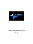
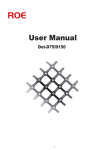
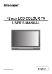
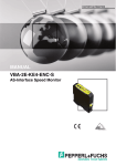
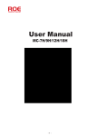
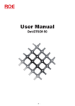
To Users of This Product
Thank you for purchasing our mini Car PC. This product adopts high-performance embedded computer hardware
It is designed for operations under relatively severe vehicular environments and featuring such unique safeguards
as anti-vibration, heat-emission, intelligent power protection, etc. The delicately optimized design meets the
requirements of all users in its applications to various conditions and occasions. This product is small in shape,
easily installed and simple to operate. Moreover, the mini Car PC is easily adaptable to a professional working
environment as well as its ease of use virtually anywhere. With its excellent quality and exquisite manufacturing
technology, your product will bring limitless entertainment and enjoyment to you.
In order to ensure the correct installation and the most efficient service, please read this user manual carefully.
Notice: Electric Safety
z
In order to prevent electric shock and possible severe damage to the unit, please temporarily remove the PC
power adapter from the power socket before moving the Car PC.
z
In order to prevent voltage fluctuations from damaging your purchase and the possibly to the vehicle’s battery,
please switch the computer’s power switch to the "off" position while starting the vehicle.
z
Once the computer’s power has been put into the "on" position do not switch the computer’s power to the
"off" position until the computer is fully booted. When shutting down the computer follow the guidelines in
this user guide.
z
Please make sure that the power voltage setting has been adjusted to the standard voltage value of the
location where the product is being used.
z
No owner/user-serviceable components exist in this unit. Allow only qualified technical service personnel to
service or open this unit. Contact our factory service department. Unauthorized tampering may void the
product warranty.
Operational Security
z
Before using this product, please first make sure that all external wires and power adapters have been
correctly connected. If you suspect any defects, please contact your sales agent or factory personnel
immediately.
z
To prevent electric short-circuiting, it is forbidden to leave any metal stuffs in the PC mainframe.
z
Dust, humidity and dramatic temperature changes will affect the usage life of this computer. Please keep the
machine away from these hazards.
z
Although an anti-vibration mechanism is adopted inside the computer, please avoid traumatic movement,
jolting or dropping of the unit.
z
In cleaning the units do not use chemical detergents. Remove dust with a soft cloth to ensure brightness. If
any technical problems occur while using this unit, please refer to our sales agents or related technicians. We
will correct any problem as rapidly as possible. Please refer to your warranty.
Table of Contents
Ⅰ. Product features
1.
2.
3.
4.
....................................................................................................................................... 1
Product applications ................................................................................................................................. 1
Product features ....................................................................................................................................... 1
Description of product functions .. ............................................................................................................ 1
Product specifications .............................................................................................................................. 2
Ⅱ. Mainframe front and rear panels
.................................................................................................... 3
(1). Mainframe instructions for front panel .................................................................................................... 3
(2). Mainframe instructions for rear panel ....................................................................................................... 4
(3). Mainframe instructions for fixed .............................................................................................................. 5
Ⅲ. System connection instructions
Ⅳ. System operation insturctions
...................................................................................................... 5
......................................................................................................... 6
1. ITPS power control ...................................................................................................................................... 6
2. Power-on/off ................................................................................................................................................ 6
Ⅴ. Troubleshooting
...................................................................................................................................... 7
Ⅵ. Product installation instructions
Ⅶ. The reference of wiring
Ⅷ. Accessories
..................................................................................................... 7
..................................................................................................................... 10
............................................................................................................................................. 10
Ⅰ. Product Features
1. Product Applications
1.1
1.2
1.3
Computer: This product can be operated as a Car PC or Home PC when adapted with a mini LCD
Monitor or Home PC Monitor. This product also can be operated as a control equipment when it
connected to mechanical equipment and touch screen.
Extension functions: with USB/COM/LPT/MIDI four ports through which the user can accessorize this
machine with a cordless keyboard and mouse, wireless earphone, GPRS Modem, GPS navigation
antenna, DVB-T, digital TV receiver, etc.
Applicative OS: WIN98/WIN2000/WIN XP/WIN 2003, the user can installed the relative OS
according to they are usage, so that it can come true: removable office, EC, entertainment, game, and
navigation all computer functions.
2. Product Features
Capability stable——Industrial design, capability stable.
Compact design——With dimensions of 255m (L) x 196mm (W) x 70 mm (H). the unit is easily installed and
transported.
High Performance Specification——We can supply CPU as your request. Compare the unit‘s smaller dimensions
and upper performance features.
Low power consumption——the maximum power consumption of this machine is only 40W, Rated power
consumption is lower than 40W. Energy savings and efficient heat emissions make the unit compatible with the
vehicle.
Professional design——The Car PC is specifically designed with poor environmental and highway conditions in
mind. Designed using optimal mechanical and electrical specifications, product features focusing on anti-vibration,
power separation and heat emissions satisfy the most demanding user. The Car pc will function superbly in severe
operating conditions including, but not limited to, temperature extremes, fluctuating power currents,
electromagnetic disturbances and rough vehicle vibrations caused by inferior road conditions.
ITPS module——This equipment has a special Intelligent Power Control(ITPS ) system:.
3. Application
Applications
Functions
In - Vehicle Use
z
z
z
z
z
z
Wireless Internet access (configured
with GPRS wireless network card)
WI-FI (WLAN)
GPS navigation (configured with GPS
antenna + GPS software)
Watch DVB-T digit TV (configured
with DVB-T antenna + special
software)
Radio function
Play multimedia such as MPEG4
PC game
Simple text processing
z
Match with vehicle sonic system
z
z
z
Personal Computer
(Accompanied with
PC Monitor)
Multimedia player
(Accompanied with
Home / Indoor Use
z
1
z
z
z
z
Wired and wireless
network access
Watch DVB-T digital
TV (configured with
USB antenna + special
software)
Play multi-media such
as MPEG4
PC game
Text processing
Match with home sonic
system
Control equipment
z
z
z
WI-FI (WLAN)
Wired network
control
Software control
equipment
PC Monitor)
4. Specifications
Item
Description
CPU
Standare positioning: Intel Pentium M 1.1GHz / 2M Cache Up to Intel
Pentium M 1.8GHz / 2M Cache
Memory
HDD
Chipset
Standare positioning: 512M (DDR 266/333/400/533 BGA) Up to 1G
Standare positioning: IDE, 5400 RPM
Optional: Up to120G
Intel 845 North Bridge
Ich * 4 South Bridge
Video card
intel (build-in display)
Audio output
AC97 6Ch, 3.1 Channels
Video output
VGA
Ethernet card
1 x RJ-45 port
10M/100M Ethernet
Wireless communication
WIFI 802.11b – USB (extension)
Bluetooth – USB (extension)
GPRS/CDMA/3G – USB (extension)
FM- USB (extension)
Rear panel interface
1 x VGA
2 x USB
1 x RJ45
1 x COM
1 x LPT
1 x MIDI
1 x MIC
1 x LIN-OUT
1 x LIN-IN
1 x PS/2 KEYBOARD
1 x PS/2 MOUSE
OS
Win 98/2000/XP/2003
Power supply
Current
Power consumption
Size
Weight
Work temperature
Storage temperature
DC 7 V — 20 V
2.3 A-3.5A
< 40W
255mm(L) x 196mm(W) x 70mm(H)
2.2 kg
0℃-50℃
-20℃-60℃
Work humidity
10%-85%
Storage humidity
10%-90%
2
Ⅱ. View of panel
(Front)
(Back)
(1) Front panel
1
2
5
4
3
1. RESET
2. POWER: Power on/off
3. Fan.
4. POW-LED (Power indicator).
5. HDD-LED (HD indicator).
3
(2) Rear panel
1
2
3
4
5
6
13
12
11
10
9
1. Radiator holes
2. PS/2 for mouse.
3. RJ-45 Ethernet interface.
4. LPT connected to printer or other external equipment.
5. MIDI interface.
6. DC IN : power input 7-20V.
7. MIC: Microphone interface
8. LIN-IN: Audio input interface
9. LIN-OUT :Audio output interface, external sonic system/earphone.
10. VGA interface
11. COM serial port.
12. USB interface.
13. PS/2 for keyboard
4
8
7
(3) Installation
Fixing holes
Ⅲ. Instructions for connection
2
3
1
4
1.
2.
3.
4.
DC IN :Connect to DC IN port.
ACC: Connect to ignition switch.
BATT-: Black is connect to cathode -;
BATT+: Yellow is connect to anode +;
5
Ⅳ. Operation instructions
(1) . ITPS instruction
A. Operationing principle instruction:
After connection the red LED of ITPS light, that means you can star up the unit then and further operation.
The ITPS will detect the high voltage from ACC when the you turn on ignition switch to ACC or start up the
automobile, if the duration of high voltage is more than 10s (this duration of high voltage will be re-recorded if the
high voltage broken off.),the green and white line will transmit boot-up signal to PC board. And then the PC will
start up properly. The green LED of ITPS will light after the PC started up.
After start up the PC you can set it to be standby/ sleep as following.
1 You can turn off the computer or to set the computer to be standby, sleep mode by the operation system.
○
2 When you turn off the ignition switch or take away the key it will cut off the voltage of ACC. And ITPS detect
○
0V voltage from ACC, the ITPS board will turn to delay turn off for 30s, after that a signal of turn off will be
transmit to the PC board by green and white line. So that the PC will enter into turn off program and turn off
safety,only +5VSB voltage supply for the main board. If some system of the computer can not close or system
halted, ITPS will keep waiting for 20s and then cut off the main power supply of PC compulsively, Only +5VSB
voltage supply for the main board.
③ If voltage of ACC get back again before the PC turn off safety after entering into delay turn off state ITPS will
not keep PC run normally. resume is high level, microcomputer
B. The protection of storage battery and others:
As the voltage range of ITPS is from DC 7V-20V, ITPS could detect the change of voltage and transmit the signal
via green white to control the PC. So that it will keep the battery out of over-discharge.
1. In standby mode if ITPS detect the voltage is less than 10.8v for 30seconds, the Red LED will light and refuse
to turn on the PC with ACC. The Red LED flicker once/s in this state. When
2. When the PC is on work if ITPS detect the voltage is less than 10.8v for 30seconds, the Red LED will light,
after 30s it will send out turn off signal which making the PC turn off normally. If the PC couldn’t turn off
normally or system halted ITPS will turn of PC compulsively.
3. In standby mode if ITPS detect the voltage is higher than 15.8v for 3s the Red LED will light and refuse to
turn on the PC with ACC. The Red LED flicker twice/s in this state.
4. When the PC is on work if the ITPS detect he voltage is higher than 15.8v for 3s the Red LED will light and
send out turn off signal which making the PC turn off normally. If the PC couldn’t turn off normally or system
halted ITPS will turn of PC compulsively.
5. In work mode the PC will turn off system normally in a delay time after the turn off signal was sent out and
enter into stand by mode. If ITPS detect that PS_ON hasn’t arrived a high voltage for 20s after the delay time,
it will send out a compulsively signal continues for 6s to turn off the PC compulsively. If there is something
wrong with the BIOS system, it will not work as mentioned above and the Red LED will light twice/s. Please
cut off the power supply and ask for a service.
6. The ITPS keep the battery enough power as mentioned above to start up automobile.
When the your automobile is out of use for a long time please disconnect the ITPS to the battery avoid the ITPS
exhaust the power of battery by low current. When the car is not use for a long time, pls cut the contaction of
automobile battery and ITPS power panel in order to avoid ITPS power panel exhaust the electric quantity of
the battery.
(2) . Power-on/off
1.
2.
3.
4.
After connect to the power, the computer will be stand-by mode.
After connect to ACC and turn on the ignition switch,10s later computer will turn on normally, the PC will
turn off normally when you turn off ACC.
Push the POWER button on the front panel to turn on the computer, push it once more to turn off and
enter into standby state. Disconnect the power supply to exit standby state.
Please push the RESET button on the front panel to reset when the system halted.
6
Ⅴ. Troubleshooting
1.
2.
3.
4.
5.
6.
The power indicator doesn’t light after you pushed the power button.
-Please check and make sure the power connection is correct and the power supply proper.
No sound
-Please check and make sure the audio lint is connected properly.
-Please check is the system is in MUTE mode or the volume is down to the minimum level.
-Check whether the driver of audio card is installed correctly.
Not display:
-Check whether the display work properly.
-Check and make sure the connection is correctly.
Couldn’t recognise USB.
-Re-insert the USB, so that the system will recognise it again.
-Insert to the other USB ports..
-Check whether the driver program is installed properly.
Display blue screen when you installing PWIN98SE.
Please check whether external hanging FDD (Floppy Drive Device), if not, please enter into
BIOS SETUP PROGRAM/STANDARD CMOS FEATURES/DRIVE A [NONE] AND INTEGATED
PERIPHERALS/ON-BOARD FDC CONTROLLER [DISABLED] or it will display blue screen when you
installing PWIN98SE.
Can’t enter into sleep mode. Recognize 160GB HDD as136GB HDD.
-160GB is a part of 48-bit HDD, it is supported by BIOS. The last BIOS can recognize it.
7.
How to start the USB2.0 function?
Because of ICH4 this unit can read four USB2.0.
We suggest that install WINXP SP2 so that it needn’t a driver for USB2.0 and could read the USB2.0, then
work normally as transmission rate of 480bit.
8.
Couldn’t find the HYPER THREADING.
This unit support HYPER THREADING, but is only work in P4 which HYPER THREADING. So that you
need to install P4 before operate on it.
Windows XP and LINUS2.4 X support H-T function.
9.
What kind of operating system support H-T function?
WINDOWS XP and WIN 2003 can support HT function.
Please reference to http://www.intel.com/support/platform/ht/os.htm for more details.
Ⅵ. Porduct installation instructions
1.The first way of installation: Set it in front of the driver seat as follows.
7
2.The second way of installation: Set it under the seat as follows.
8
3. The third way of installation: Set in the tank of your automobile as follows.
9
Ⅶ. The reference of wiring
Ⅷ. Accessories
Name
Quantity
Mainframe
One
Three-core automobile
power connection cable
One
Driver disc
One
Instruction manual
One
Fixed screw
One package
10
11