1
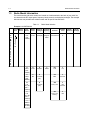
Portable Radios
PRO Series™
Portable Radios
contact
contact
control
control
C
A, Motorola, Professional Radio, PRO Series and PRO
Model numbers are marks of Motorola. LTR¨ is a registered
trademark of E.F. Johnson Company. Transcrypt¨ is a registered trademark of Transcrypt International, Inc. PassPort¨
is a registered trademark of Trident Microsystems, Inc.
© 2000 Motorola, Inc. All rights reserved. Printed in USA.
*6881088C45*
68P81088C45-C
Basic
Service Manual
Professional Radio
PRO5350™
PRO5450™
PRO7350™
i
SAFETY INFORMATION
IMPORTANT INFORMATION ON SAFE AND EFFICIENT OPERATION
READ THIS INFORMATION BEFORE USING YOUR TWO-WAY RADIO
The information provided in this document supersedes the general safety information contained in user guides
published prior to July 2000. For information regarding radio use and hazardous atmosphere please refer to
the Factory Mutual (FM) Approval Manual Supplement or Instruction Card, which is included with radio
models that offer this capability.
RF Operational Characteristics
Your radio contains a transmitter and a receiver. When it is ON, it receives and transmits radio frequency (RF))
energy.
Exposure To Radio Frequency Energy
Your Motorola Two-Way Radio, is designed to comply with the following National and International Standards and
Guidelines regarding exposure of human beings to radio frequency electromagnetic energy (EME):
•
United States Federal Communications Commission, Code of Federal Regulations
(47 CFR part 2 sub-part J)
•
American National Standards Institute (ANSI)/Institute of Electrical and Electronic Engineers (IEEE)
(C95.1 - 1992)
•
Institute of Electrical and Electronic Engineers (IEEE) (C95.1-1999 Edition)
•
National Council on Radiation Protection and Measurements (NCRP) of the United States (Report 86,
1986)
•
International Commission on Non-Ionizing Radiation Protection (ICNRP - 1998)
•
National Radiological Protection Board of the United Kingdom (1995)
•
Ministry of Health (Canada) Safety Code 6. Limits of Human Exposure to Radio frequency Electromagnetic Fields in the Frequency Range from 3 kHz to 300 GHz (1999)
•
Australian Communications Authority Radiocommunications (Electromagnetic Radiation - Human Exposure) Standard (1999) (applicable to wireless phones only)
PORTABLE RADIO OPERATION AND EME EXPOSURE
To assure optimal radio performance and make sure human exposure to radio frequency electromagnetic
energy is within the guidelines set forth in the above standards, always adhere to the following procedures:
Antenna Care
Use only the supplied or an approved replacement antenna. Unauthorized antennas, modifications, or
attachments could damage the phone and may violate FCC regulations.
DO NOT hold the antenna when the two-way radio is “IN USE”. Holding the antenna affects call quality
and may cause the radio to operate at a higher power level than needed.
Two-Way Radio Operation
When using your radio as a traditional two-way radio, hold the radio in a vertical position with the
microphone one to two inches (2.5 to 5 cm) away from the lips.
MAN WITH RADIO
ii
Safety Information
Body-Worn Operation
To maintain compliance with FCC RF exposure guidelines, if you wear a radio on your body when transmitting,
always place the radio in a Motorola supplied or approved clip, holder, holster, case, or body harness.
Use of non-Motorola-approved accessories may exceed FCC RF exposure guidelines. If you do not use a
body-worn accessory, ensure the antenna is at least one inch (2.5 cm) from your body when
transmitting.
Data Operation
When using any data feature of the radio, with or without an accessory cable, position the antenna of the
radio at least one inch (2.5 cm) from the body.
Approved Accessories
For a list of approved Motorola accessories look in the accessory section of this manual.
ELECTROMAGNETIC INTERFERENCE/COMPATIBILITY
Note:
Nearly every electronic device is susceptible to electromagnetic interference (EMI) if inadequately
shielded, designed or otherwise configured for electromagnetic compatibility.
• FACILITIES
To avoid electromagnetic interference and/or compatibility conflicts, turn off your radio in any facility where
posted notices instruct you to do so. Hospitals or health care facilities may be using equipment that is
sensitive to external RF energy.
•
AIRCRAFT
When instructed to do so, turn off your radio when on board an aircraft. Any use of a radio must be in
accordance with applicable regulations per airline crew instructions.
•
MEDICAL DEVICES
•
Pacemakers
The Health Industry Manufacturers Association recommends that a minimum separation of 6 inches (15
cm) be maintained between a handheld wireless radio and a pacemaker.These recommendations are
consistent with the independent research by, and recommendations of, Wireless Technology Research.
Persons with pacemakers should:
• ALWAYS keep the radio more than six inches (15 cm) from their pacemaker when the radio is turned ON.
• not carry the radio in the breast pocket.
• use the ear opposite the pacemaker to minimize the potential for interference.
• turn the radio OFF immediately if you have any reason to suspect that interference is taking place.
• Hearing Aids
Some digital wireless radios may interfere with some hearing aids. In the event of such interference, you may
want to consult your hearing aid manufacturer to discuss alternatives.
• Other Medical Devices
If you use any other personal medical device, consult the manufacturer of your device to determine if it is
adequately shielded from RF energy. Your physician may be able to assist you in obtaining this information.
Safety Information
iii
SAFETY AND GENERAL
•
Use While Driving
Check the laws and regulations on the use of radios in the area where you drive. Always obey them
When using your radio while driving, please:
•
Give full attention to driving and to the road.
•
Use hands-free operation, if available.
•
Pull off the road and park before making or answering a call if driving conditions so require.
OPERATIONAL WARNINGS
•
FOR VEHICLES WITH AN AIR BAG
!
WARNING
Do not place a portable radio in the area over an air bag or in the air bag deployment area. Air bags inflate
with great force. If a portable radio is placed in the air bag deployment area and the air bag inflates, the radio
may be propelled with great force and cause serious injury to occupants of the vehicle.
•
POTENTIALLY EXPLOSIVE ATMOSPHERES
Turn off your radio prior to entering any area with a potentially explosive atmosphere, unless it is a radio type
especially qualified for use in such areas as “Intrinsically Safe” (for example, Factory Mutual, CSA, or UL
Approved). Do not remove, install, or charge batteries in such areas. Sparks in a potentially explosive
atmosphere can cause an explosion or fire resulting in bodily injury or even death.
Note: The areas with potentially explosive atmospheres referred to above include fueling areas such as
below decks on boats, fuel or chemical transfer or storage facilities, areas where the air contains
chemicals or particles, such as grain, dust or metal powders, and any other area where you would normally be advised to turn off your vehicle engine. Areas with potentially explosive atmospheres are
often but not always posted.
•
BLASTING CAPS AND AREAS
To avoid possible interference with blasting operations, turn off your radio when you are near electrical
blasting caps, in a blasting area, or in areas posted: “Turn off two-way radio”. Obey all signs and instructions.
OPERATIONAL CAUTIONS
•
ANTENNAS
!
Caution
Do not use any portable radio that has a damaged antenna. If a damaged antenna comes into contact
with your skin, a minor burn can result.
•
BATTERIES
All batteries can cause property damage and/or bodily injury such as burns if a conductive material such as
jewelry, keys, or beaded chains touch exposed terminals. The conductive material may complete an electrical
circuit (short circuit) and become quite hot. Exercise care in handling any charged battery, particularly when
placing it inside a pocket, purse, or other container with metal objects.
iv
Safety Information
This page intentionally left blank
v
Table of Contents
Chapter 1
1.1
1.2
1.3
Scope of Manual ............................................................................................... 1-1
Warranty and Service Support.......................................................................... 1-1
1.2.1
Warranty Period and Return Instructions ............................................ 1-1
1.2.2
After Warranty Period .......................................................................... 1-1
1.2.3
Piece Parts Availability ........................................................................ 1-2
1.2.4
Technical Support................................................................................ 1-3
1.2.5
Warranty and Repairs.......................................................................... 1-3
Radio Model Information................................................................................... 1-4
Chapter 2
2.1
2.2
3.3
3.4
3.5
3.6
3.7
Intrinsically Safe Radio Information
FMRC Approved Equipment ............................................................................. 2-1
Repair of FMRC Approved Products ................................................................ 2-2
2.2.1
Repair .................................................................................................. 2-2
2.2.2
Relabeling............................................................................................ 2-2
2.2.3
Do Not Substitute Options or Accessories .......................................... 2-2
Chapter 3
3.1
3.2
Introduction
Maintenance
Introduction ....................................................................................................... 3-1
Preventive Maintenance ................................................................................... 3-1
3.2.1
Inspection ............................................................................................ 3-1
3.2.2
Cleaning Procedures ........................................................................... 3-1
Safe Handling of CMOS and LDMOS Devices ................................................. 3-2
Repair Procedures and Techniques — General ............................................... 3-2
Disassembling and Reassembling the Radio — General ................................. 3-3
Radio Disassembly — Detailed ........................................................................ 3-4
3.6.1
Front Cover from Chassis Disassembly .............................................. 3-4
3.6.2
Chassis Assembly Disassembly.......................................................... 3-6
3.6.3
Keypad and Keypad/Option Board Disassembly................................. 3-7
3.6.4
Display Disassembly ........................................................................... 3-8
3.6.5
Speaker, Microphone, and Universal Connector Flex Disassembly.... 3-8
3.6.6
PTT Disassembly .............................................................................. 3-10
3.6.7
Control Top Disassembly .................................................................. 3-10
Radio Reassembly — Detailed ....................................................................... 3-10
3.7.1
Control Top Reassembly ................................................................... 3-10
3.7.2
PTT Reassembly ............................................................................... 3-10
vi
3.8
3.9
3.10
3.11
3.12
3.13
3.7.3
Speaker, Microphone, and Universal Connector Flex Reassembly...3-11
3.7.4
Keypad and Keypad Option Board Reassembly................................3-11
3.7.5
Chassis Assembly Reassembly.........................................................3-12
3.7.6
Chassis and Front Cover Reassembly ..............................................3-12
3.7.7
DTMF Retrofit Kit Procedure (Optional Upgrade Procedure) ............3-13
3.7.8
Option Board Installation....................................................................3-14
PRO5150/PRO5350/PRO5450 Radio Exploded Mechanical View and
Parts List..........................................................................................................3-15
PRO7150/PRO7350/PRO7450 Radio Exploded Mechanical View and
Parts List..........................................................................................................3-16
PRO9150/PRO9450 Radio Exploded Mechanical View and Parts List ..........3-17
Service Aids.....................................................................................................3-19
Test Equipment ...............................................................................................3-21
Configuring and Wiring the Programming/Test Cable .....................................3-22
Chapter 4
4.1
4.2
4.3
4.4
General..............................................................................................................4-1
RF Test Mode....................................................................................................4-1
Test Frequencies for Display and Non-Display Radios .....................................4-6
Receiver Performance Tests .............................................................................4-7
Chapter 5
5.1
5.2
5.3
5.4
5.5
Radio Tuning, Programming, Cloning, and Lowband Antenna Cutting
Procedure
Introduction........................................................................................................5-1
Global Radio Tuning Setup ...............................................................................5-1
5.2.1
Initial Test Equipment Setup ................................................................5-2
CPS Programming Setup ..................................................................................5-2
Cloning (Conventional Only)..............................................................................5-3
5.4.1
Error Codes (Display Radios Only)......................................................5-3
Lowband Molded Antenna Cut Chart ................................................................5-4
Chapter 6
6.1
6.2
6.3
Transceiver Performance Testing
Power Up Self-Test
Error Codes - Conventional Radios...................................................................6-1
Error Codes .......................................................................................................6-1
Operation Display Codes...................................................................................6-2
vii
Chapter 7
7.1
7.2
7.3
7.4
7.5
7.6
7.7
7.8
7.9
7.10
7.11
7.12
7.13
Chapter 8
8.1
8.2
8.3
8.4
8.5
8.6
8.7
8.8
8.9
8.10
8.11
8.12
8.13
8.14
Accessories
Antennas ............................................................................................. 7-1
Carrying Accessories........................................................................... 7-1
Carry Cases......................................................................................... 7-2
Chargers.............................................................................................. 7-2
Batteries .............................................................................................. 7-3
Adaptors .............................................................................................. 7-3
Miscellaneous...................................................................................... 7-3
Service Aids......................................................................................... 7-3
Audio Accessories ............................................................................... 7-4
Option Boards...................................................................................... 7-5
Remote Speaker Microphones ............................................................ 7-5
Manuals ............................................................................................... 7-5
Retrofit Front Cover Kits ...................................................................... 7-6
Model Chart and Test Specifications
UHF 403-470 MHz ............................................................................................ 8-1
UHF 450-527 MHz ............................................................................................ 8-2
UHF 403-470 MHz (MPT) ................................................................................. 8-3
UHF 450-527 MHz (MPT) ................................................................................. 8-4
UHF 403-470 MHz (LTR).................................................................................. 8-4
UHF 450-527 MHz (LTR).................................................................................. 8-5
VHF 136-174 MHz ............................................................................................ 8-5
Low Band 29.7-42/35-50MHz ........................................................................... 8-6
800 MHz (LTR) ................................................................................................. 8-6
800 MHz (Privacy Plus) .................................................................................... 8-7
Specifications - PRO5150/PRO5350/PRO5450 Radios ................................... 8-7
Specifications - PRO7150/PRO7350/PRO7450 Radios ................................. 8-10
Specifications - PRO9150/PRO9450 Radios.................................................. 8-12
Specifications - 800 MHz Radio...................................................................... 8-14
Glossary of Terms .......................................................................................................... G-1
viii
Notes
1-1
Chapter 1
Introduction
1.1
Scope of Manual
This manual is intended for use by service technicians familiar with similar types of equipment. It
contains service information required for the equipment described and is current as of the printing
date. Changes which occur after the printing date may be incorporated by a complete Manual revision
or alternatively as additions.
NOTE Before operating or testing these units, please read the Safety Information Section in the
front of this manual.
1.2
Warranty and Service Support
Motorola offers support which includes: full exchange and/or repair of the product during the warranty
period; and service/ repair or spare parts support out of warranty. Any “return for exchange” or “return
for repair” to an authorized Motorola Dealer must be accompanied by a Warranty Claim Form.
Warranty Claim Forms are obtained by contacting an Authorized Motorola Dealer. (See section 1.2.4
on page 1-3.)
1.2.1 Warranty Period and Return Instructions
The terms and conditions of warranty are defined fully in the Motorola Dealer or Distributor or Reseller
contract. These conditions may change from time to time, and the following subsections are for
guidance purposes only.
In instances where the product is covered under a “return for replacement” or “return for repair”
warranty, a check of the product should be performed prior to shipping the unit back to Motorola. This
is to ensure that the product has been correctly programmed or has not been subjected to damage
outside the terms of the warranty.
Prior to shipping any radio back to the appropriate Motorola warranty depot, please contact Customer
Resources (Please see page 2 and page 3 in this chapter.). All returns must be accompanied by a
Warranty Claim Form, available from your Customer Resources representative. Products should be
shipped back in the original packaging, or correctly packaged to ensure that no damage occurs in
transit.
1.2.2 After Warranty Period
After the Warranty period, Motorola continues to support its products in two ways:
1. Motorola's Radio Parts and Service Group (CGISS) offers repair service to users and dealers at
competitive prices.
2. RPSG supplies individual parts and modules that can be purchased by dealers who are capable
of performing fault analysis and repair.
1-2
Warranty and Service Support
1.2.3 Piece Parts Availability
Some replacement parts, spare parts, and/or product information can be ordered directly. If a
complete Motorola part number is assigned to the part, and it is not identified as Depot ONLY, it is
available from the Accessories and Aftermarket Division (AAD). If no part number is assigned, the
part is not normally available from Motorola. If the part number is appended with an asterisk, the part
is serviceable by a Motorola Depot only. If a parts list is not included, this generally means that no
user-serviceable parts are available for that kit or assembly.
To Order Parts in Latin America and the Caribbean:
7:00 A. M. to 7:00 P. M. (Central Standard Time)
Monday through Friday (Chicago, U. S. A.)
1-847-538-8023
Motorola Parts
Accessories and Aftermarket Division
Attention: Order Processing
1313 E. Algonquin Road
Schaumburg, IL 60196
Parts Identification
1-847-538-0021 (Voice)
1-847-538-8194 (Fax)
Warranty and Service Support
1-3
1.2.4 Technical Support
Technical support is available to assist the dealer/distributor in resolving any malfunction which may
be encountered. Initial contact should be by telephone to Customer Resources wherever possible.
When contacting Motorola Technical Support, be prepared to provide the product model number and
the unit’s serial number.
Latin America and Caribbean Depots
(Motorola, Plantation, Florida, U. S. A.)
1-800-694-2161
1-954-723-3008
1.2.5 Warranty and Repairs
For warranty and repairs, contact Motorola Technical Support as listed below. Be prepared to provide
the product model number and the unit’s serial number.
Colombia
Brazil
Motorola de Colombia
Motorola Do Brasil
Diagonal 127A 17-64
Rua Bandeira Paulista, 580
Santa Fe de Bogota
04532-001 Sao Paulo - SP
Colombia
Brazil
Phone: 571-615-5759
Phone: 5511-821-9991
Puerto Rico
Fax: 5511-828-0157
Motorola de Puerto Rico
Mexico
A Street #21
Motorola De Mexico
Mario Julia Industrial Park
Huatabampo #50
Puerto Nuevo, Puerto Rico 00922
COL. Roma Sur
Phone: 787-273-2400
Mexico D.F. 06700
Fax: 787-782-3685
Mexico
Phone: 525-574-1513
Fax: 525-564-2188
1-4
1.3
Radio Model Information
Radio Model Information
The model number and serial number are located on a label attached to the back of your radio. You
can determine the RF output power, frequency band, protocols, and physical packages. The example
below shows one portable radio model number and its specific characteristics.
Table 1-1.
Radio Model Number
Example: LAH25KDC9AA3
Type of Model
Unit
Series
H
H = Portable
AA or LA = Motorola Internal Use
AA
or
LA
25
Freq.
Band
Power
Level
Physical
Packages
Channel
Spacing
K
VHF
(136174MHz)
C
2.5W
C
No Display
9
Programmable
AA
Conventional
2F
R
UHF1
(403470MHz)
D
4-5W
D
Keypad
6
25kHz
DU
LTR
16F
S
UHF2
(450520MHz)
E
6W
H
1-Line Display
CK
MPT
256F LTR
B
Low
Band, R1
(29.742.0MHz)
C
Low
Band, R2
(35.050.0MHz)
U
800MHz
(806-821)
(851-866)
N
4-Line Display
Protocol
Feature
Level
Model
Revision
Model
Package
2
A
N
3
5
GB
6
Privacy Plus
128F
256F LTR
GE
8
Privacy Plus
Roaming
160F
2-1
Chapter 2
Intrinsically Safe Radio Information
2.1
FMRC Approved Equipment
Anyone intending to use a radio in a location where hazardous concentrations of flammable material
exist (hazardous atmosphere) is advised to become familiar with the subject of intrinsic safety and
with the National Electric Code NFPA 70 (National Fire Protection Association) Article 500 (hazardous
[classified] locations).
An Approval Guide, issued by Factory Mutual Research Corporation (FMRC), lists manufacturers and
the products approved by FMRC for use in such locations. FMRC has also issued a voluntary
approval standard for repair service (“Class Number 3605”).
FMRC Approval labels are attached to the radio to identify the unit as being FM Approved for
specified hazardous atmospheres. This label specifies the hazardous Class/Division/Group along
with the part number of the battery that must be used. Depending on the design of the portable unit,
this FM label can be found on the back of the radio housing or the bottom of the radio housing.Their
Approval mark is shown below.
FM
APPROVED
!
WARNING: Do not operate radio communications equipment in a hazardous atmosphere
unless it is a type especially qualified (e.g. FMRC Approved) for such use. An explosion or
fire may result.
WARNING: Do not operate the FMRC Approved Product in a hazardous atmosphere if it has
been physically damaged (e.g. cracked housing). An explosion or fire may result.
WARNING: Do not replace or charge batteries in a hazardous atmosphere. Contact sparking
may occur while installing or removing batteries and cause an explosion or fire.
WARNING: Do not replace or change accessories in a hazardous atmosphere. Contact
sparking may occur while installing or removing accessories and cause an explosion or fire.
WARNING: Do not operate the FMRC Approved Product unit in a hazardous location with the
accessory contacts exposed. Keep the connector cover in place when accessories are not
used.
WARNING: Turn radio off before removing or installing a battery or accessory.
WARNING: Do not disassemble the FMRC Approved Product unit in any way that exposes
the internal electrical circuits of the unit.
Radios must ship from the Motorola manufacturing facility with the hazardous atmosphere capability
and FM Approval labeling. Radios will not be “upgraded” to this capability and labeled in the field.
A modification changes the unit’s hardware from its original design configuration. Modifications can
only be done by the original product manufacturer at one of its FMRC audited manufacturing facilities.
2-2
Repair of FMRC Approved Products
!
WARNING: Failure to use an FMRC Approved Product unit with an FMRC Approved battery
or FMRC Approved accessories specifically approved for that product may result in the dangerously unsafe condition of an unapproved radio combination being used in a hazardous
location.
Unauthorized or incorrect modification of an FMRC Approved Product unit will negate the Approval
rating of the product.
2.2
Repair of FMRC Approved Products
REPAIRS FOR MOTOROLA FMRC APPROVED PRODUCTS ARE THE RESPONSIBILITY OF THE
USER.
You should not repair or relabel any Motorola manufactured communication equipment bearing the
FMRC Approval label (“FMRC Approved Product”) unless you are familiar with the current FMRC
Approval standard for repairs and service (“Class Number 3605).
You may want to consider using a repair facility that operates under 3605 repair service approval.
!
WARNING: Incorrect repair or relabeling of any FMRC Approved Product unit could
adversely affect the Approval rating of the unit.
WARNING: Use of a radio that is not intrinsically safe in a hazardous atmosphere could
result in serious injury or death.
FMRC’s Approval Standard Class Number 3605 is subject to change at any time without notice to
you, so you may want to obtain a current copy of 3605 from FMRC. Per the December, 1994
publication of 3605, some key definitions and service requirements are as follows:
2.2.1 Repair
A repair constitutes something done internally to the unit that would bring it back to its original
condition Approved by FMRC. A repair should be done in an FMRC Approved facility.
Items not considered as repairs are those in which an action is performed on a unit which does not
require the outer casing of the unit to be opened in a manner which exposes the internal electrical
circuits of the unit. You do not have to be an FMRC Approved Repair Facility to perform these actions.
2.2.2 Relabeling
The repair facility shall have a method by which the replacement of FMRC Approval labels are
controlled to ensure that any relabeling is limited to units that were originally shipped from the
Manufacturer with an FM Approval label in place. FMRC Approval labels shall not be stocked by the
repair facility. An FMRC Approval label shall be ordered from the original manufacturer as needed to
repair a specific unit. Replacement labels may be obtained and applied by the repair facility providing
satisfactory evidence that the unit being relabeled was originally an FMRC Approved unit. Verification
may include, but is not limited to: a unit with a damaged Approval label, a unit with a defective housing
displaying an Approval label, or a customer invoice indicating the serial number of the unit and
purchase of an FMRC Approved model.
2.2.3 Do Not Substitute Options or Accessories
The Motorola communications equipment certified by Factory Mutual is tested as a system and
consists of the FM Approved portable, FM Approved battery, and FM Approved accessories or
options, or both. This Approved portable and battery combination must be strictly observed. There
must be no substitution of items, even if the substitute has been previously Approved with a different
Motorola communications equipment unit. Approved configurations are listed in the FM Approval
guide published by FMRC, or in the product FM Supplement. This FM Supplement is shipped with FM
Repair of FMRC Approved Products
2-3
Approved radio and battery combination from the manufacturer. The Approval guide, or the Approval
standard Class Number 3605 document for repairs and service, can be ordered directly through
Factory Mutual Research Corporation located in Norwood, Massachusetts.
3-1
Chapter 3
Maintenance
3.1
Introduction
This chapter provides details about the following:
●
●
●
●
●
3.2
Preventive maintenance (inspection and cleaning)
Safe handling of CMOS and LDMOS devices
Disassembly and reassembly of the radio
Installation of Optional Retrofit Kit
Installation of Option Boards
Preventive Maintenance
The radios do not require a scheduled preventive maintenance program; however, periodic visual
inspection and cleaning is recommended.
3.2.1 Inspection
Check that the external surfaces of the radio are clean, and that all external controls and switches are
functional. It is not recommended to inspect the interior electronic circuitry.
3.2.2 Cleaning Procedures
The following procedures describe the recommended cleaning agents and the methods to be used
when cleaning the external and internal surfaces of the radio. External surfaces include the front
cover, housing assembly, and battery case. These surfaces should be cleaned whenever a periodic
visual inspection reveals the presence of smudges, grease, and/or grime.
NOTE Internal surfaces should be cleaned only when the radio is disassembled for service
or repair.
The only recommended agent for cleaning the external radio surfaces is a 0.5% solution of a mild
dishwashing detergent in water. The only factory recommended liquid for cleaning the printed circuit
boards and their components is isopropyl alcohol (70% by volume).
!
CAUTION: Certain chemicals and their vapors can have harmful effects on certain plastics.
Avoid using aerosol sprays, tuner cleaners, and other chemicals.
Cleaning External Plastic Surface
Apply the 0.5% detergent-water solution sparingly with a stiff, non-metallic, short-bristled brush to
work all loose dirt away from the radio. Use a soft, absorbent, lintless cloth or tissue to remove the
solution and dry the radio. Make sure that no water remains entrapped near the connectors, cracks, or
crevices
Cleaning Internal Circuit Boards and Components
Isopropyl alcohol (70%) may be applied with a stiff, non-metallic, short-bristled brush to dislodge
embedded or caked materials located in hard-to-reach areas. The brush stroke should direct the
dislodged material out and away from the inside of the radio. Make sure that controls or tunable
components are not soaked with alcohol. Do not use high-pressure air to hasten the drying process
3-2
Safe Handling of CMOS and LDMOS Devices
since this could cause the liquid to collect in unwanted places. After completing of the cleaning
process, use a soft, absorbent, lintless cloth to dry the area. Do not brush or apply any isopropyl
alcohol to the frame, front cover, or back cover.
NOTE Always use a fresh supply of alcohol and a clean container to prevent contamination
by dissolved material (from previous usage).
3.3
Safe Handling of CMOS and LDMOS Devices
Complementary metal-oxide semiconductor (CMOS) devices are used in this family of radios, and are
susceptible to damage by electrostatic or high voltage charges. Damage can be latent, resulting in
failures occurring weeks or months later. Therefore, special precautions must be taken to prevent
device damage during disassembly, troubleshooting, and repair.
Handling precautions are mandatory for CMOS circuits and are especially important in low humidity
conditions. DO NOT attempt to disassemble the radio without first referring to the following CAUTION
statement.
!
CAUTION: This radio contains static-sensitive devices. Do not open the radio
unless you are properly grounded. Take the following precautions when
working on this unit:
●
●
●
●
●
●
●
●
3.4
Store and transport all CMOS devices in conductive material so that all exposed leads are
shorted together. Do not insert CMOS devices into conventional plastic “snow” trays used
for storage and transportation of other semiconductor devices.
Ground the working surface of the service bench to protect the CMOS device. We
recommend using the Motorola Static Protection Assembly (part number 0180386A82),
which includes a wrist strap, two ground cords, a table mat, and a floor mat.
Wear a conductive wrist strap in series with a 100k resistor to ground. (Replacement wrist
straps that connect to the bench top covering are Motorola part number RSX-4015.)
Do not wear nylon clothing while handling CMOS devices.
Do not insert or remove CMOS devices with power applied. Check all power supplies used
for testing CMOS devices to be certain that there are no voltage transients present.
When straightening CMOS pins, provide ground straps for the apparatus used.
When soldering, use a grounded soldering iron.
If at all possible, handle CMOS devices by the package and not by the leads. Prior to
touching the unit, touch an electrical ground to remove any static charge that you may
have accumulated. The package and substrate may be electrically common. If so, the
reaction of a discharge to the case would cause the same damage as touching the leads.
Repair Procedures and Techniques — General
Parts Replacement and Substitution
When damaged parts are replaced, identical parts should be used. If the identical replacement part is
not locally available, check the parts list for the proper Motorola part number and order the part from
the nearest Motorola Communications parts center listed in Chapter 1 of this manual.
Rigid Circuit Boards
This family of radios uses bonded, multi-layer, printed circuit boards. Since the inner layers are not
accessible, some special considerations are required when soldering and unsoldering components.
The printed-through holes may interconnect multiple layers of the printed circuit. Therefore, exercise
care to avoid pulling the plated circuit out of the hole.
When soldering near the 20-pin and 40-pin connectors:
●
Avoid accidentally getting solder in the connector.
Disassembling and Reassembling the Radio — General
●
●
3-3
Be careful not to form solder bridges between the connector pins.
Examine your work closely for shorts due to solder bridges.
Flexible Circuits
The flexible circuits are made from a different material than the rigid boards, and require different
soldering techniques. Excessive prolonged heat on a flexible circuit can damage the material.
Therefore, avoid excessive heat and excessive bending.
For parts replacement, use the ST-1087 Temperature-Controlled Solder Station with a 600-700
degree tip, and use small diameter solder such as ST-633. The smaller size solder will melt faster and
require less heat to be applied to the circuit.
To replace a component on a flexible circuit:
1. Grasp with seizers (hemostats) the edge of the flexible circuit near the part to be removed.
2. Pull gently.
3. Apply the tip of the soldering iron to the component connections while pulling with the seizers.
NOTE Do not attempt to puddle-out components. Prolonged application of heat may
damage the flexible circuit.
3.5
Disassembling and Reassembling the Radio — General
Since these radios may be disassembled and reassembled with the use of only four (board to casting)
screws, it is important to pay particular attention to the snaps and tabs, and how parts align with each
other.
The following tools are required for disassembling the radio:
●
●
●
Chassis/front cover disassembly tool
Penknife-size screwdriver
TORX™ T6 screwdriver
If a unit requires more complete testing or service than is customarily performed at the basic level,
send this unit to a Motorola Authorized Service Center. (See Chapter 1 for a list of authorized service
centers.)
3-4
3.6
Radio Disassembly — Detailed
Radio Disassembly — Detailed
The paragraph that follow describe how to disassemble the radio. This includes the following major
components:
●
●
●
●
●
●
●
Front cover
Chassis
Keypad,
Keypad/option board
Display assembly
Speaker, microphone, universal flex connector
PTT assembly
3.6.1 Front Cover from Chassis Disassembly
1. Turn off the radio.
2. Pull down on the two battery-release buttons.
3. With the buttons pulled down, the top of the battery will fall from the radio.
4. Remove the battery completely from the radio.
Battery
Release
Buttons
Battery
Figure 3-1. Battery Removal
5. Remove the antenna.
6. Using the chassis and knob opener tool, remove the volume and channel selector knobs off of
their shafts as shown in Figure 3-2.
NOTE Both knobs slide on and off. However, they are supposed to fit very tightly on their
shafts.
7. Separate the chassis from the internal electronics front cover assembly by inserting the chassis
and knob opener tool in between the thin retaining wall and the chassis at the bottom of the radio
as shown in Figure 3-3. Do not mar the housing O-ring sealing area.
8. Slowly pry the bottom of the chassis from the cover by pushing the chassis and knob opener tool
back while rotating the handle of the tool over and behind the base of the radio. This prying action
forces the thin inner plastic wall toward the base of the radio, releasing the two chassis base tabs.
Radio Disassembly — Detailed
3-5
S
OB
KN
ER
EN
OP
Chassis and
Knob Opener
A
H
C
S
R
E
N
E
P
1
O
0
Z
2
0
7
0
8
IS
C
6
6
S
Insert opener between
knob and switch base,
then pry off knob
Knobs
Figure 3-2. Knob Removal
KNOB
S OP
ENER
Chassis and
Knob Opener
R
NE
PE
S
SI
AS
CH
O
1
Z0
02
07
C8
66
Radio
Chassis
Figure 3-3. Chassis Removal
!
Marring the front cover O-ring sealing area will prevent the radio from sealing
properly.
9. Lay the chassis down. Rotate the front cover backward and slightly away from the chassis.
NOTE
CAUTION: Flexible ribbon circuits (flexes) connecting the front cover assembly
and the chassis prevent you from completely separating the two units. Display
radios and radios with option boards have two flexes. The PRO9150 will not lay
flat with the two units separated.
3-6
Radio Disassembly — Detailed
10. Lift the latches on the main circuit board to release the flexes from their connectors as shown in
Figure 3-4.
Latches
Flex Connectors
Figure 3-4. Unlatching Flex Connectors
NOTE At this point, if necessary, the DTMF Retrofit Kit Procedure can be performed. (See
paragraph 3.7.7).
3.6.2 Chassis Assembly Disassembly
1. If disassembly of the chassis or the main board is required, then use a TORX™ screwdriver with a
T6 head to remove the four screws holding the main board to the chassis.
2. Lift the main board from the chassis as shown in Figure 3-5.
Screws (4)
Compliant
Ground
Contact
Main
Board
Radio
Chassis
O-Ring
Retaining
Features
Figure 3-5. Main Board from Chassis Removal
Radio Disassembly — Detailed
!
3-7
CAUTION: Refer to the CMOS CAUTION in paragraph 3.3 before removing the main board.
Be sure to use ESD protection when handling circuit boards.
3. Remove the small O-ring retainers from their slots in the chassis. Note the alignment of the
retainers for reassembly.
4. Remove the O-ring.
5. (VHF, UHF, and lowband only) If required in disassembly, slide off the ground contact from the top
corner boss of the radio chassis.
3.6.3 Keypad and Keypad/Option Board Disassembly
1. If the disassembly of the keypad or the keypad printed circuit board, is required, lift the
microphone flex circuit up, and carefully remove the microphone and its boot from the front cover
pocket as shown in Figure 3-6.
2. Lay this flex circuit to one side.
3. To remove the keypad retainer shield, Insert the tip of a “penknife size,” flat blade screwdriver in
the opening at the end of the keypad retainer arm tab. Pry the tab away from the side of the front
cover until it moves past the ledges on the side wall. Repeat this procedure for the four remaining
retainer arm tabs.
Flat Blade
Screwdriver
Speaker-Microphone
Flex Circuit Tail
Keypad Retainer
Arm Tabs (4)
Retainer
Top Hooks
Retainer
Figure 3-6. Retainer Removal
4. Note that for the PRO series, with the exception of the PRO9150, the two “top hooks” are still held
underneath the front cover—right below the speaker. Lift the keypad retainer out of the front
cover, then lift and pivot the two hooks out of the front cover.
5. Lift latch on connector located on the keypad board to release the display flex.
6. The keypad/option board and the keypad can be removed without the use of tools
NOTE At this point, the Option Board Installation Procedure should be performed, if
necessary (See paragraph 3.7.8)
3-8
Radio Disassembly — Detailed
Retainer
Display
Module
Keypad
Option
Board
Keypad
Radio
Body
Figure 3-7. Keypad Retainer and Other Boards Removable
3.6.4 Display Disassembly
1. If disassembly involves the removal of the display module, with the keypad retainer removed,
disconnect the display flex from the keypad option board connector by lifting the latch on the
connector.
!
CAUTION: Take care not to damage the display. Do not cut, bend, or pinch the heat seal.
Display modules contain CMOS devices. Be sure to use ESD protection.
2. For the PRO7150 and PRO7350, the display module is attached to the front cover with a doublesided adhesive pad. Carefully pull up on the display module, lifting only at the bottom corners,
remove it from the front cover. Use a new piece of double-sided adhesive to re-mount the display
to the cover.
3. For the PRO9150 only, The display module snaps into the front cover assembly. Insert two flat
blade screwdrivers between the flexible beam at the top of the display module (one on each side).
Deflect the beam down until it moves past the hooks on the front cover. The display module is
hooked to the front cover at the base of the display. Lift the top of the display module past the
hooks and remove from front cover.
3.6.5 Speaker, Microphone, and Universal Connector Flex Disassembly
1. If disassembly of the speaker-microphone assembly is necessary, remove the dustcover by
turning the screw at the bottom of the dustcover counterclockwise with your fingers. Lift the
dustcover out of its pocket.
NOTE The dustcover must be removed to remove the speaker-microphone assembly flex
circuit.
Radio Disassembly — Detailed
3-9
NOTE The speaker is held in place with a two-legged retainer bracket. The bracket legs are
secured by slots in the front cover. Be careful not to damage the speaker when
removing the retainer bracket.
2. Using a screwdriver, push down on the portion of the speaker retainer bracket pointing toward the
bottom of the radio. Then, remove the retainer by slightly pushing it toward the top of the radio
until you slide it past the front cover slot.
3. Using care not to pull on the flex cable, pull the rubber microphone boot from its seated position.
Unless you are replacing the microphone, leave it in the boot.
NOTE The PRO9150 radio has a different microphone and microphone boot then is used in
the other PRO series models. These are NOT interchangeable.
NOTE The speaker-microphone assembly flex circuit goes through the front cover wall to
the outside wall. To replace this assembly, you must peel-off the universal connector
escutcheon label. The existing escutcheon cannot be reassembled; a new part must
be used. (See item number 10 on the exploded view drawing on paragraph 3.8).
4. Peel-off the universal connector flex circuit escutcheon (label).
5. Carefully pry the flex circuit (adhesive held) backer board away from the front cover, and remove
the universal connector tail of the speaker-microphone assembly through its opening in the front
cover. After the universal connector tail of the speaker-microphone assembly is removed, the
assembly can be completely removed. If it is necessary to replace the speaker or microphone, or
both, do it while the flex circuit is removed from the front cover.
Speaker
Universal
Connector
Tail
Speaker Orientation
Tab (12:00 Position)
Microphone
Boot
Microphone
Note: PRO7150 radio shown
as an example only.
Speaker Microphone
Flex Circuit Assembly
Figure 3-8. Speaker-Microphone Removal
3-10
Radio Reassembly — Detailed
3.6.6 PTT Disassembly
If required, the PTT bezel and the PTT seal assembly can be disassembled using a small screwdriver
as follows:
T-Shaped
Retainer Tab
PTT
Bezel
Tab
Tab
PTT
Seal
Figure 3-9. PTT Removal
1. Pry back the T-tab found inside the front cover (in between the four buttons on the PTT assembly).
2. Remove the PTT bezel by slightly bowing it until the top and bottom tabs are released from the
slots in the front cover.
3. The PTT seal can be easily lifted from the bezel without the use of tools.
3.6.7 Control Top Disassembly
1. To remove the control top assembly, place a screwdriver next to the antenna boss, then pry it
against the control top escutcheon. This lifts the control top escutcheon away from its
double-sided adhesive. Grab the double-sided adhesive near the volume potentiometer, then lift it
away.
2. Remove the integrated control top seal, emergency button, and remove the transmit light pipe.
3.7
Radio Reassembly — Detailed
The paragraph that follow describe how to reassemble the radio. This includes the following major
components:
●
●
●
●
Control top
Speaker, microphone, universal flex connector
Keypad/option board
Chassis and front cover
3.7.1 Control Top Reassembly
1. Replace transmit light pipe and control top seal.
2. Peel off the liners from a new control top escutcheon and place it in the recess in the front cover.
Press the control top escutcheon firmly against the adhesive.
3.7.2 PTT Reassembly
1. Put the PTT seal in the PTT bezel.
2. Place the bezel top tab in the top slot inside the front cover PTT opening. Slightly bow the bezel
so that the bottom tab can fall inside the bottom slot.
3. Press the PTT assembly against the front cover opening.
NOTE Look inside the front cover to make sure the T-tab is fully engaged with the front
cover. If necessary, press the T-tab toward the top of the radio until it becomes fully
engaged.
Radio Reassembly — Detailed
3-11
3.7.3 Speaker, Microphone, and Universal Connector Flex Reassembly
1. Feed the universal connector tail of the speaker-microphone flex assembly through the opening in
the side wall of the front cover.
2. Peel-off the adhesive liner on the back of the universal connector tail of the flex circuit. Attach the
flex tail to the front cover using the guide pins for correct alignment.
3. Replace the universal connector escutcheon. Make sure that all the connector openings align
with the gold pads on the flex circuit.
4. Align the notch in the speaker at the twelve o’clock position with the tab on the front cover as
shown in Figure 3-8.
5. Place the speaker retainer bracket into the hole on the top of the front cover, and bend the
retainer down to fit underneath the boss below the speaker.
6. If display, keypad, or keypad option board are not involved, reinsert the microphone and boot into
the pocket in the front cover
3.7.4 Keypad and Keypad Option Board Reassembly
1. If you are replacing the PRO7150 or PRO7350 display, use a new double-sided adhesive display
pad (item number 17 on the exploded view diagram in paragraph 3-8). Take care to avoid touching
the display lens.
2. If you are replacing the PRO9150 display, place the tabs at the bottom of the display into the
reliefs in the front cover. Gently snap the beam at the top of the display under the hooks in the
front cover. Take care to avoid touching the front of the display or the display lens.
3. Replace the keypad, and the keypad/option board. Insert display module flex tail into connector
on keypad option board. Push down on latch, closing it securely.
!
CAUTION: Take care not to damage the display. Do not cut, bend, or pinch the heat seal.
Display modules contain CMOS devices. Be sure to use ESD protection.
4. For PRO7150 or PRO7350, insert the “top hooks” of the keypad retainer into the slots below the
speaker (above the display) in the front cover. For all models, snap all four of the retainer arm tabs
in place in the front cover.
NOTE If speaker and microphone not removed, pull the speaker-microphone flex circuit out
of the way during reassembly.
5. Reinsert the microphone and boot into the pocket in the front cover (PRO5150 and PRO7150
cylinder, PRO9150 clam shell).
6. Lay the speaker-microphone flex on top of keypad/option board retainer.
Catches
Retainer
Figure 3-10. Lock Retainer Catches to Radio Body
3-12
Radio Reassembly — Detailed
3.7.5 Chassis Assembly Reassembly
Before assembling the main RF board to the chassis, ensure that the following steps are done to the
chassis.
1. Slide on the ground contact (if it was removed) on the top corner boss of the chassis. Do not bend
the fingers that extend from this contact.
2. Replace the O-ring. The tabs on the O-ring should reach into the chassis and point down.
3. Stretch the O-ring to place it into the retaining pocket at the bottom end of the chassis.
NOTE When properly assembled, the retainers on the O-ring should align with the slots on
the chassis. If this is not the case, remove and replace the O-ring until it is aligned
with the chassis and completely seated in place around the perimeter.
Before assembling the main RF board to the chassis, ensure that the following additional steps are
done to the chassis.
1. Ensure that the antenna nut insulator is correctly replaced by pushing it all the way to the top of
the antenna nut.
2. Replace the battery contact seal (if necessary) surrounding the battery contact.
3. Place the main circuit board straight down on top of the chassis.
NOTE Be sure the battery contact seal protrudes through the chassis and is not pinched
under the chassis.
4. Use the T6 TORX screwdriver to fasten the screws holding the main board to the chassis.
5. Do not over torque. Torque limit is 3 inch lbs.
3.7.6 Chassis and Front Cover Reassembly
1. Align the chassis assembly end-to-end with the front cover assembly.
2. Insert the tails of the flex circuits into their respective connectors at the bottom of the front cover.
3. Push down the latches on the connectors to hold the flex circuits to the main board.
4. Slide the volume potentiometer and frequency switch shafts into their respective holes in the front
cover.
5. Push the chassis assembly completely into the top of the front cover until it settles in place.
6. Be sure the O-ring is properly seated.
7. Snap the bottom of the chassis into the front cover.
8. Reassemble the knobs, dust cover, antenna, and battery.
Radio
Chassis
Figure 3-11. Fastening the Chassis
Radio Reassembly — Detailed
3-13
3.7.7 DTMF Retrofit Kit Procedure (Optional Upgrade Procedure)
If you are performing an upgrade from a PRO5150 or PRO5350 model with no keypad to a PRO5150
or PRO5350 DTMF model, replace the existing front cover kit with kit number HLN9987 and follow the
reassembly steps to reassemble the upgraded radio. (See paragraph 3.7 for details about
reassembly.)
To activate the retrofit using the radio software, follow these steps:
1. Start the Customer Programming Software (CPS).
2. Read the codeplug data by clicking on the READ icon in the menu bar, or by selecting READ
DEVICE in the pulldown menu.
3. Open the Radio Configuration dialog box. (See Figure 3-12.)
Figure 3-12. Activating the Retrofit
4. Change the Keypad Configuration from “No Keypad” to “Programmable/Numeric”.
5. Write the codeplug back to the radio by clicking on the WRITE icon in the menu bar, or by
selecting WRITE DEVICE in the pulldown menu.
NOTE The CPS may display a warning dialog box when you attempt to write the codeplug
back to the radio. It is safe to ignore this warning. Press the OK button.
3-14
Radio Reassembly — Detailed
3.7.8 Option Board Installation
1. With the keypad retainer removed and the display flex disconnected as shown in Figure 3-13, the
keypad backer board can be removed without the use of tools.
2. Remove the jumper flex from the connector on the keypad board. Notice the orientation of the flex
to the connector. Arrows on the jumper flex point to the correct way of inserting the flex into the
connector.
3. Discard the keypad backer board.
4. The “breakaway” tab at the top of all option boards contains an extra row of keys and is used only
for PRO9150 models.
5. For other PRO series models, break-off and discard the option board tab, taking care not to
damage the option board. Trim any tab fragments that may remain on the option board.
Retainer
Jumper
Flex
TO KP
Keypad/
Option
Board
Display
Flex
Note: PRO7150 radio shown
as an example only.
Figure 3-13. Changing Keypad/Option Board
6. Reassemble the option board to the front cover assembly.
7. Insert the display flex circuit into the connector on the option board.
8. Insert the jumper flex circuit into the connector on the option board. Notice the orientation of the
flex circuit. Arrows on the jumper flex point to the correct way of inserting the flex into the
connector.
9. For other PRO series models, replace the retainer by placing the two top hooks into the slots
below the speaker in the front cover; then, pivot the retainer into the front cover. For all radio
models, ensure that all four tab arms snap correctly into the front cover.
10. With the speaker microphone/keypad option board, display, and retainer correctly in place, the
front cover assembly can now be reassembled per paragraph 3.7.6.