1
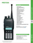
3.11 Service Aids
3-19
3.11 Service Aids
Table 3-1 lists service aids recommended for working on the PRO5150/PRO5350/PRO5450,
PRO7150/PRO7350/PRO7450, and PRO9150/PRO9450 radios.
NOTE While all of these items are available from Motorola, most are standard shop equipment items,
and any equivalent item capable of the same performance may be substituted for the item
listed.
Table 3-1.
Motorola
Part No.
Description
Service Aids
Application
RLN4460
Portable Test Set
Enables connection to audio/accessory jack. Allows
switching for radio testing.
HVN9027
Customer Programming Software (CPS): CD ROM.
Includes images for high density, 1.4 Mbyte, 3.5” floppy diskettes.
Programs customer option and channel data. Tunes
hardware parameters, front end, power, deviation,
etc. Conventional and LTR products.
HVN9031
Customer Programming Software (CPS).
Same as above (MPT protocol products).
HVN9045
Customer Programming Software (CPS).
Same as above (800 MHz LTR protocol products).
HVN9065
Customer Programming Software (CPS).
Same as above (Privacy Plus protocol products).
AARKN4075
Programming Cable
Includes radio interface box (RIB) capability.
AARKN4074
Programming Cable/Test
Cable
Connects radio to RIB (RLN4008B).
AARKN4073
Radio to Radio Cloning Cable
Allows radio to be duplicated from a master radio by
transferring programmed data from the master radio
to the other.
RLN4008
Radio Interface Box
Enables communications between radio and computer’s serial communications adapter.
HLN9756
BNC Adaptor
Adapts radio antenna port to BNC cabling of equipment (VHF and UHF , B1 only)
5880313B69
SMA to BNC adapter
Adapts radio antenna port to BNC cabling of equipment (800 MHz radios)
HHLN4133A
Rhombic tip adapter (Yellow)
Adapts radio antenna port to BNC cabling of test
equipment.
HHLN4134A
Cylindrical tip adapter (Blue)
Adapts radio antenna port to BNC cabling of test
equipment.
RLN4510
Battery Eliminator 7.5V Regulator
Works in combination with Shop Battery Block,
0180305G54.
3-20
3.11 Service Aids
Motorola
Part No.
Description
AA0180305G54
AA8180384F68
AA8180384F66
Shop Battery Block
Bench Test Housing Eliminator
Bench Test Housing Eliminator
Interconnects radio to power supply. Provides for
troubleshooting of radio when housing is removed.
For use with PRO9150 long frame radio.
0180357A57
Wall-Mounted Power Supply
(120 VAC)
Used to supply power to RIB.
0180358A56
Wall-Mounted Power Supply
(220 VAC; 2-prong)
Used to supply power to RIB.
3080369B72
Computer Interface Cable
Connects computer’s serial communications adapter
to RIB (RLN4008B).
AAHLN9742A
Radio Software Upgrade
Cable
Used with MPT protocol products.
6680702Z01
Service Tool
Remove radio chassis and knobs.
Application
3.12 Test Equipment
3-21
3.12 Test Equipment
Table 3-2 lists test equipment required to service the PRO5150/PRO5350/PRO5450, PRO7150/
PRO7350/PRO7450, and PRO9150/PRO9450 radios.
Table 3-2.
Motorola Part
No.
Description
Recommended Test Equipment
Characteristics
This monitor will
substitute for items
listed below with an
asterisk *
Application
R2000, R2600
R2400, or R2001
with trunking
option
Service Monitor
Frequency/deviation meter and signal generator for wide-range troubleshooting and alignment
*R1049
Digital Multimeter
*S1100
Audio Oscillator
67 to 200Hz tones
Used with service monitor for injection of PL tones
*S1053,
*SKN6009,
*SKN6001
AC Voltmeter,
Power Cable
for meter,
Test leads for meter
• 1 mV to 300 V
• 10 MΩ input impedance
Audio voltage measurements
R1053
Dual-trace Oscilloscope
20 MHz bandwidth,
5 mV/cm - 20 V/cm
Waveform measurements
*S1350,
Wattmeter,
*ST1215 (VHF)
*ST1223 (UHF)
Plug-in Elements
(VHF & UHF), RF
Transmitter power output measurements
*T1013
Dummy Load
• 50 Ω
• ±5% accuracy
10 W, max. 0-1000
MHz, 300 W
S1339
RF Millivolt Meter
100 µV to 3 VRF, 10
kHz to 1.2 GHz
RF level measurements
*R1013
SINAD Meter
S1347 or
S1348 (prog)
DC Power Supply
Two meters recommended for AC/
DC voltage and current measurements
Receiver sensitivity measurements
0-20 Vdc, 0-5 Amps
Bench supply for 7.5Vdc
3-22
3.13 Configuring and Wiring the Programming/Test Cable
3.13 Configuring and Wiring the Programming/Test Cable
Block
Figure 3-14. Programming/Test Cable AARKN4074
Figure 3-15. Pin Configuration of the Cable Side Connector
3.13 Configuring and Wiring the Programming/Test Cable
3-23
P1
TO RADIO
UNIVERSAL
CONNECTOR
P2
TO RADIO
TEST SET
RLN4460
EXT SPKR +
EXT SPKR OPTION B+
EXT MIC
OPT SEL 2
OPT SEL 1
GND
RX DATA
TX DATA
RSSI
XMIT/RX AUDIO
1
2
3
4
5
6
7
8
9
10
11
1
2
5
7
8
9
15
16
18
19
20
21
22
BOOT CTRL
N/C
12
25
AUDIO AUDIO +
MIC AUDIO
GND
VOL CTRL
DISC
PTT
OPT SEL INT/EXT
BOOT CTRL
13
J1
TO RIB
RLN4008
10K
1
4
11
15
25
GND
BIAS
BUS BUS +
BOOT CTRL
FL0830062O
Figure 3-16. Programming /Test Cable Schematic
3-24
3.13 Configuring and Wiring the Programming/Test Cable
This page intentionally left blank
4-1
Chapter 4
Transceiver Performance Testing
4.1
General
These radios meet published specifications through their manufacturing process by utilizing highaccuracy laboratory-quality test equipment. The recommended field service equipment approaches
the accuracy of the manufacturing equipment with few exceptions. This accuracy must be maintained
in compliance with the manufacturer’s recommended calibration schedule.
4.2
RF Test Mode
When the radio is operating in its normal environment, the radio’s microcontroller controls the RF
channel selection, transmitter key-up, and receiver muting. However, when the unit is on the bench for
testing, alignment, or repair, it is removed from its normal environment and cannot receive commands
from its system. Therefore, the internal microcontroller does not key the transmitter or unmute the
receiver. This prevents the use of a normal tuning procedure. To solve this problem, a special “test
mode” is incorporated into the radio.
Note: The test mode procedure that follows assumes that the Customer Programming Software Front
Panel Access screen has both the FPA and RF TEST boxes selected. Select from the programming
screen to enable or disable certain features of the radio RF test mode.
●
●
●
FPA entry not selected blocks all test modes.
FPA entry selected and RF TEST not selected blocks RF test mode.
FPA entry selected and RF TEST selected enables all test modes.
To enter the test mode for a display radio:
1. Turn the radio on.
2. Within ten seconds after the self test is complete, press side button 2, shown in Figure
4-1, five times in succession.
3. After “CSQ CHXX SP25” appears on the display, the radio is on channel XX (see Note
below), carrier squelch mode, 25 kHz channel spacing. Each additional press of side
button 2 (see Table 4-2) scrolls to the next channel spacing, and a corresponding set of
tones are sounded. Refer to Figure 4-2 for test mode information for a four-line display
radio.
4. Press side button 1 to scroll through the test environments listed in Table 4-1.
5. Press side button 2 for 3 seconds to switch the radio to the control head test mode.
‘LCD Test’ appears on the display.
6. Press side button 1 to turn on all the dots of the first character. Another side button 1
press turns on all the dots of the next character, continuing until the last character is
reached.
7. Press side button 1 at the end of the LCD test to activate the ‘Icon Test’. The next side
button 1 press turns on the first icon.
8. Press side button 1 at the end of the Icon Test to activate the button test. Pressing any
side button (except side button 1), or any keypad button during the LCD test or Icon test
immediately activates this test. A good button press is verified by a chirp.
4-2
RF Test Mode
9. Press side button 2 for 3 seconds in the control head test mode to return the radio to the
RF Test mode.
10. Turn radio off to exit test mode.
Note:
XX = channel number (01 - 14)
To enter the test mode for a non-display radio:
1. Turn the radio on.
2. Within ten seconds after the self test is complete, press side button 2 (Figure 4-1) five
times in succession.
3. Press side button 1 the number of times listed in Table 4-1 to get the number of corresponding beeps.
4. Turn radio off to exit test mode.
5. To access all 14 test modes on a 4-channel radio, the frequency knob and mechanical
stop sleeve must be removed (see paragraph 3-8 exploded view diagram).
Button Test (For models with ”G” in location 10 of model number Example: LAH25UCH6GB6AN)
1. Press the orange button; “3/1” appears which indicates that switch 3 is in the closed condition.
2. Release the orange button; “3/0” appears which indicates that switch 3 is in the open condition.
3. Rotate the mode selector knob; “4/0”through “4/15” appears which indicates that knob 4 is in
mode position 1 through 15.
4. Rotate the volume control; “2/0” through “2/255” appears.
5. Press SB1, view “96/1”; release, view “96/0”.
6. Press SB2, view “97/1”; release, view “97/0”.
7. Press SB3, view “98/1”; release view “98/0”.
8. Press PTT button, view “1/1”; release view “1/0”.
Keypad (For models with ”G” in location 10 of model number Example: LAH25UCH6GB6AN)
1. Press 0, view “48/1”; release, view “48/0”.
2. Press 1, view “49/1”; release, view “49/0”.
3. Press 2, view “50/1”; release, view “50/0”.
4. Press 3, view “51/1”; release, view “51/0”.
5. Press 4, view “52/1”; release, view “52/0”.
6. Press 5, view “53/1”; release, view “53/0”.
7. Press 6, view “54/1”; release, view “54/0”.
8. Press 7, view “55/1”; release, view “55/0”.
9. Press 8, view “56/1”; release, view “56/0”.
10. Press 9, view “57/1”; release, view “57/0”.
11. Press *, view “58/1”; release, view “58/0”.
12. Press #, view “59/1”; release, view “59/0”.
13. Press <, view “128/1”; release, view “128/0”.
14. Press HOME, view “129/1”; release, view “129/0”.
RF Test Mode
4-3
15. Press >, view “130/1”; release, view “130/0”.
16. Press Option Select1, view “135/1”; release, view “135/0”.
17. Press Option Select2, view “136/1”; release, view “136/0”.
18. Press Option Select3, view “137/1”; release, view “137/0”.
19. Pressing SB2 for 3 seconds in the Control Head Test mode will cause the radio to return to the RF
Test mode.
Channel
Selector
itch
On/Off
Switch
1
2
3
Figure 4-1. Radio Side Button Locations
Annunciators
Test Mode
Information,
Line 2
1
2
3
4
Figure 4-2. Four-Line Display
4-4
RF Test Mode
Table 4-1.
Number
of Side
Button 1
Presses
Test Environments (Side Button 1)
No. of
Beeps
Display
Shows
Initial (No
button
presses
required)
0
CSQ
Carrier Squelch
RX: if carrier detected
TX: mic audio
1
1
TPL
Tone Private-Line
RX: unsquelch if carrier and tone (192.8Hz)
detected
TX: mic audio + tone (192.8Hz)
2
2
DPL
Digital PrivateLine
RX: unsquelch if carrier and digital code (131)
detected
TX: mic audio + digital code (131)
3
3
DTMF
Dual-Tone Multiple
Frequency
RX: unsquelch if carrier detected
TX: selected DTMF tone pair
4
5
Open
Unsquelch
RX: constant unsquelch
TX: mic audio
5
9
HSS
MDC1200
RX: unsquelch if carrier detected
TX: 1500Hz tone
6
11
CMP
Compander
RX: if carrier detected
TX: mic audio
7
12
LLE
Low-Level Expand
RX: if detected
TX: mic audio
Table 4-2.
Description
Function
Test Enviornments (Models with ”G” in location 10 of model number EX: LAH25UCH6GB6AN)
Item
No.
No. of
Beeps
1
1
GKC
Carrier Squelch
RX: unsquelch if carrier detected
TX: mic audio
2
1
BKC
Tone
Private-Line
RX: unsquelch if carrier and tone (192.8Hz) detected
TX: mic audio + tone (192.8Hz)
3
2
BKC
Digital
Private-Line
RX: unsquelch if carrier and digital code (131) detected
TX: mic audio + digital code (131)
4
3
BKC
Dual-Tone multiple frequency
RX: unsquelch if carrier detected
TX: selected DTMF tone pair
5
5
BKC
Open squelch
OSQ
RX: constant unsquelch
TX: mic audio
Description
Function
RF Test Mode
4-5
Item
No.
No. of
Beeps
6
8
BKC
Trunking Low
Speed TLS
RX: unsquelch if carrier detected
TX: mic audio + connect tone (105-8 MHz)
7
9
BKC
Trunking High
Speed THS
RX: unsquelch if valid outbound signalling word (OSW)
detected
TX: 1500Hz tone
8
11
BKC
CMP
RX: unsquelch if carrier detected
TX: mic audio
9
12
BKC
LLE
RX: unsquelch if carrier detected
TX: mic audio
Description
Table 4-3.
Function
Test Channel Spacing (Side Button 2)
Number of Low Tones
Channel Spacing
1
25/30 kHz
2
12.5 kHz
3
20 kHz
4-6
4.3
Test Frequencies for Display and Non-Display Radios
Test Frequencies for Display and Non-Display Radios
The radio channels and test frequencies are listed in Table 4-4. The channels are selected using the
channel selector switch located on top of the radio, as shown in Figure 4-1. The test environment and
channel spacing for any particular frequency is selected using side buttons 1 and 2, as listed in Tables
4-1, 4-2, and 4-4. The display radio shows the selected parameters on the radio display, and sounds
the corresponding number of beeps and tones listed in Tables 4-1 and 4-3. The non-display radio only
sounds the beeps and tones.
Table 4-4.
Test Frequencies (Using the Channel Selector Switch)
Channel
Selector
Switch
Position
Test
Channel
Low 1
Low 2
VHF
UHF 1
UHF 2
800
1 Low Power
8 High Power
TX #1 or #8
RX #1 or #8
29.740
29.740
35.040
35.040
136.025
136.025
403.025
403.025
450.025
450.025
806.025
806.075
2 Low Power
9 High Power
TX #2 or #9
RX #2 or #9
32.040
32.020
37.040
37.020
142.325
142.325
413.025
413.025
462.850
462.850
815.475
809.175
3 Low Power
10 High Power
TX #3 or #10
RX #3 or #10
34.040
34.020
39.040
39.020
148.625
148.625
425.025
425.025
475.675
475.675
824.925
812.325
4 Low Power
11 High Power
TX #4 or #11
RX #4 or #11
36.040
36.020
42.040
42.020
154.925
154.925
437.025
437.025
488.500
488.500
837.975
815.575
5 Low Power
12 High Power
TX #5 or #12
RX #5 or #12
38.040
38.020
45.040
45.020
161.225
161.225
449.025
449.025
501.325
501.325
851.025
818.675
6 Low Power
13 High Power
TX #6 or #13
RX #6 or #13
40.040
40.020
48.040
48.020
167.525
167.525
460.025
460.025
514.150
514.150
860.475
821.825
7 Low Power
14 High Power
TX #7 or #14
RX #7 or #14
42.040
42.020
50.040
50.020
173.825
173.825
469.975
469.975
526.975
526.975
869.975
824.975
Receiver Performance Tests
4.4
4-7
Receiver Performance Tests
The receiver and transmitter performance tests are contained in Tables 4-5 and 4-6 respectively.
Refer to Chapter 5, Figure 5-1, for test equipment setup. Note that all test measurements are taken at
25°C.
Table 4-5.
Test Name
Receiver Performance Checks
Service Monitor
Radio
Test Set
Comments
Reference
Frequency
Mode: PWR MON
4th channel test frequency*
Monitor: Frequency error
Input at RF In/Out
TEST MODE,
Test Channel
4 carrier
squelch output at
antenna
PTT to continuous (during the
performance
check)
Frequency error to be
±200 Hz VHF
±600 Hz UHF
±60 Hz Low Band
Rated Audio
Mode: GEN
Output level: 1.0mV RF
4th channel test frequency*
Mod: 1kHz tone at
3kHz deviation
Monitor: DVM: AC Volts
TEST MODE
Test Channel
4 carrier
squelch
PTT to OFF
(center), meter
selector to
Audio PA
Set volume control to
3.16Vrms
Distortion
As above, except to distortion
As above
As above
Distortion 3.0%
Typical
Sensitivity
(SINAD)
As above, except SINAD,
lower the RF level for 12dB
SINAD.
As above
PTT to OFF
(center)
RF input to be
0.25µV
Noise
Squelch
Threshold
(only radios
with conventional system need to
be tested)
RF level set to 1mV RF
As above
PTT to OFF
(center), meter
selection to
Audio PA,
speaker/load to
speaker
Set volume control to
3.16Vrms
As above, except change frequency to a conventional
system. Raise RF level from
zero until radio unsquelches.
out of TEST
MODE; select
a conventional system
As above
Unsquelch to occur at
<0.25µV.
Preferred SINAD =
9-10dB
* see Table 4-4
4-8
Receiver Performance Tests
Table 4-6.
Transmitter Performance Checks
(Models with ”G” in location 10 of model number EX:LAH25KDF9GA3)
Test
Name
Service Monitor
Radio
Test Set
Reference
Frequency
Mode: PWR MON
4th channel test frequency*
Monitor: Frequency error
Input at RF In/Out
TEST MODE,
Test Channel
4 carrier
squelch
PTT to continuous (during the
performance
check)
Frequency error
±200 Hz VHF
±600 Hz UHF
±60 Hz Low Band
Power RF
As above
As above
As above
Refer to Specifications
Voice
Modulation
(internal)
Mode: PWR MON
4th channel test frequency*
atten to -70, input to RF In/
Out
TEST MODE,
Test Channel
4 carrier
squelch output at
antenna
Remove modulation input
Press PTT switch on
radio. Say “four” loudly
into the radio mic.
Measure deviation:
VHF, UHF, 800MHz,
Low 1 and Low 2:
≥ 4.0 kHz but ≤ 5.0 kHz
(25 kHz Ch Sp)
Voice
Modulation
Mode: PWR MON
4th channel test frequency*
atten to -70, input to RF In/
Out
Monitor: DVM, AC Volts
Set 1kHz Mod Out level for
0.025Vrms at test set,
80mVrms at AC/DC test set
jack
As above
As above, meter
selector to mic
Deviation:
VHF, UHF, 800MHz,
Low 1 and Low 2
≥ 4.0 kHz but ≤ 5.0 kHz
(25 kHz Ch Sp) Global.
5 kHz (20 kHz Ch Sp)
U.S. and Canada.
High-Speed
Data Modulation***
As above
TEST MODE,
Test Channel
4 high speed
output at
antenna
PTT to continuous (during the
performance
check).
Deviation: 800MHz,
VHF, UHF, Low 1 and
Low 2: ≥ 2.5 kHz but ≤
3.5 kHz (25 kHz Ch
Sp)
Low-Speed
Data Modulation
800,UHF
As above
TEST MODE,
Test Channel
4 TLS output
at antenna
PTT to continuous (during the
performance
check)
Deviation:
VHF, UHF, 800MHz, :
≥500Hz but ≤ 1000Hz
(25 kHz Ch Sp).
DTMF
Modulation
As above,
4th channel test frequency*
TEST MODE,
Test Channel
4 DTMF output at
antenna
As above
Deviation:
VHF, UHF, 800MHz,
Low 1and Low 2:
≥ 3.05 kHz but ≤ 3.45
kHz (25 kHz Ch Sp)
PL/DPL
Modulation
As above
4th channel test frequency*
BW to narrow
TEST MODE,
Test Channel
4
TPL
DPL
As above
Deviation:
VHF, UHF, 800MHz,
Low 1 and Low 2:
≥500Hz but ≤ 1000Hz
(25 kHz Ch Sp).
*** MDC
* See Table 4-4
Comments
5-1
Chapter 5
Radio Tuning, Programming, Cloning, and Lowband
Antenna Cutting Procedure
5.1
Introduction
This chapter provides an overview of the Customer Programming Software (CPS) and tuner program
designed for use in a Windows 95/98 environment. These programs are available in separate kits as
listed in the Table 5-1. An installation instruction manual is also included with each kit.
Note: Refer to the appropriate program on-line help files for the programming procedures.
Table 5-1. Software Installation Kits Radio Tuning Setup
Description
Kit Number
CPS, Conventional and UHF Radios
5.2
HVN9027/H5197
CPS, 800MHz LTR
HVN9045
CPS, Privacy Plus
HVN9065
CPS, MPT Trunking Dealers
HVN9031
Global Radio Tuning Setup
A personal computer (PC), Windows 95/98, and a global tuner program are required to tune the radio.
To perform the tuning procedures, the radio must be connected to the PC, radio interface box (RIB),
and test equipment shown in Figure 5-1.
+12VDC
Power
Supply
30 dB Pad
Service Monitor
or Counter
30 dB Pad
Wattmeter
Double Male Transmit
Battery
Eliminator
7.5V Reg.
RLN4510
Radio
Battery Block
0180305G54
RF Adaptor
HLN9756
3.5 mm to
Ferrule BNC
BNC
Program/Test Cable
AARKN 4074
RF Generator
Receive
Audio In
Tx Audio Generator
Test Box
RLN4460A
Rx
or B
Sinad Meter
AC Voltmeter
DB15
AC Plug
120/230 Vac
RIB
RLN-4008
RIB Power Supply
0180357A57 (120V)
0180358A56 (230V)
DB9
Tx Data
Rx Data
Gnd
Computer Interface
Cable 3080369B72
Figure 5-1. Radio Tuning Test Equipment Setup
5-2
CPS Programming Setup
5.2.1 Initial Test Equipment Setup
The supply voltage is connected to the radio using a Motorola battery eliminator, P/N
AA0180305G54. The initial test equipment (Figure 5-1) control settings are listed in Table 5-2.
Note: Refer to appropriate program on-line help files for the tuning procedures.
Table 5-2.
Initial Equipment Control Settings
Service Monitor
Test Set
Monitor Mode: Power Monitor
Speaker set: A
Voltage: 7.5Vdc
RF Attenuation: -70
Speaker/load:
Speaker
DC on/standby:
Standby
AM, CW, FM: FM
PTT: OFF
Volt Range: 10V
Oscilloscope Source: Mod
Oscilloscope Horizontal: 10mSec/Div
Oscilloscope Vertical: 2.5kHz/Div
Oscilloscope Trigger: Auto
Monitor Image: Hi
Monitor BW: Nar
Monitor Squelch: mid CW
Monitor Volume: 1/4 CW
5.3
Power Supply
Current: 2.5A
CPS Programming Setup
The CPS programming setup, shown in Figure 5-2, is used to program the radio codeplug.
Note: Refer to appropriate program on-line help files for the codeplug programming procedures.
Radio
Battery
Block
0180305G54
Battery
Eliminator
7.5V Reg.
RLN4510
+12VDC
Power
Supply
Test Box
RLN4460A or B
Program/
Test Cable
AARKN 4074
NOTE: Ribless Programming Cable
is part number RKN4075
DB15
DB9
RIB
RLN-4008
Computer Interface
Cable
3080369B72
RIB Power Supply
120/230 Vac
Figure 5-2. CPS Programming Setup
Tx Data
Rx
Data
Gnd
Cloning (Conventional Only)
5.4
5-3
Cloning (Conventional Only)
Cloning is the process of copying the content of one radio (source radio) into another radio (target
radio). Radio content refers to system-type features such as frequency, squelch type options,
trunking, etc.
Note: Cloning can be performed only on radios with identical model numbers and software options.
Radio functionality inherent in one radio cannot be cloned to another radio that does not contain the
same functionality. Tuning and alignment information are not transferable and are not affected by
cloning.
Signaling Identification Numbers (IDs) are duplicated in the cloning process. Unique IDs may be
assigned with the CPS.
Note: Unsuccessful cloning attempts will not damage the radio.
Procedure:
1. Turn source and target radios off.
2. Connect cloning cable to side connector of both radios.
3. Turn on target radio.
4. On source radio, simultaneously press side buttons 1 and 2, shown in Figure 5-3, then turn radio
on. Both radios produce a “clone-entry” tone and turn on their green LEDs. Display radios show
“Cloning To” (source radio) and “Program” (target radio).
5. Release both side buttons. The electronic transfer process begins and will take approximately one
to three minutes.
6. When cloning is completed, both radios reset themselves and turn their green LEDs off. The
source radio produces a “clone-exit” tone and displays “Clone Complete”.
7. Turn both radios off.
8. Disconnect the cloning cable from both radios and turn them on for normal operation.
On/Off
Switch
1
2
3
Figure 5-3. Radio Side Button Locations
5.4.1 Error Codes (Display Radios Only)
●
●
“ERR: Mismatch” - The model numbers or the code plug versions are not the same for both radios.
Cloning cannot be performed.
“ERR: Timeout” - Communication between the two radios was not established or was disrupted
during the cloning process. If this occurs, check the cloning cable and all connections. Repeat the
cloning procedure.
5-4
Lowband Molded Antenna Cut Chart
5.5
Lowband Molded Antenna Cut Chart
This chart is for antenna NAB6064 used with professional radio series.
TOP OF ANTENNA
30 31 32
FREQUENCY IN MHZ
33 34 35 36
37 38 39 40
41 42
43 44
45 46 47 48 49 50
0
0.5
(1.3 cm)
C
U
T
L
E
N
G
T
H
I
N
1.0
(2.5 cm)
1.5
(3.8 cm)
2.0
(5.1 cm)
2.5
(6.4 cm)
3.0
(7.6 cm)
3.5
I
N (8.9 cm)
C
4.0
H
E (10.2 cm)
S
4.5
(11.4 cm)
5.0
(12.7 cm)
5.5
(14.0 cm)
Note: The above chart is not drawn to scale. Obtain and use a standard ruler for marking of cutting
measurements.
Frequency Verification Chart
This chart can be used to verify the length or frequency
of an antenna already cut. DO NOT use it to make the actual cut.
Freq (MHz)
30
32
34
36
38
40
42
44
46
48
50
Final Antenna
Length (Inches)
11 9/16 (29.369 cm)
11 7/16 (29.052 cm)
10 5/8 (26.988 cm)
10 (25.400 cm)
9 3/8 (23.813 cm)
8 7/8 (22.543 cm)
8 5/16 (21.114 cm)
7 7/8 (20.003 cm)
7 1/2 (19.050 cm)
7 3/16 (18.256 cm)
6 7/8 (17.463 cm)
Note:
Antenna length
measured from
top of antenna
to bottom of
rubber skirt.
Cutting Instructions
1. Remove cap from antenna.
2. Measure from top of antenna down to the
desired length corresponding with the desired
frequency.
3. Mark the antenna, then cut at that mark.
4. To replace the antenna cap, put a small bead
of #414 Loctite™ (Motorola part number 1110019B59)
around the inside walls of the antenna cap. Place
the cap on top of the antenna and seat fully.
6-1
Chapter 6
Power Up Self-Test
6.1
Error Codes - Conventional Radios
Turning on the radio starts a self-test routine that checks the RAM, ROM checksum, EEPROM
hardware, and EEPROM checksum. If these checks are successful, the radio generates two highpitched self-test pass tones, or a musical tone (selected in CPS). If the self-test is not successful, one
low-pitched tone is heard. Radios with displays are able to display the error codes. The displayed
error codes and related corrections are listed as follows:
Table 6-1: Powe-up Display Codes - (Conventional Radios)
If the error code
displayed is...
then, there is
a...
To correct the problem...
“RAM TST ERROR”
RAM test failure.
Retest the radio by turning it off and turning it on
again. If message reoccurs, replace RAM (U405).
“ROM CS ERROR”
Wrong ROM checksum.
Reprogram FLASH memory, then retest. If message
reoccurs, replace ROM (U406).
“EEPRM HW ERROR”
Codeplug structure
mismatch or non
existence of
codeplug.
Reprogram codeplug with correct version and retest
radio. If message reoccurs, replace EEPROM
(U407).
“EEPRM CS ERROR”
Wrong codeplug
checksum.
Reprogram codeplug.
No Display
Bad display module
connection or damaged display module.
Check connection between main board and display
module or replace with new display module.
6.2
Error Codes
(For models with “G” in location10 of model number. Example: LAH25UCH6GBAN
At power-up, the radio performs cursory tests to determine if its basic electronics and software are in
working order. Problems detected during these tests are presented as error codes on the radio
display. The presence of an error code should prompt the user that a problem exists and that a service
technician should be contacted.
6-2
Operation Display Codes
Self-test errors are classified as either fatal or non-fatal. Fatal errors will inhibit user operation, nonfatal errors will not. Use Table 6-2: Power-up Display Codesto aid in understanding particular powerup error code displays.
Table 6-2: Power-up Display Codes
Type of
Failure
Description
FAIL 01/81
FATAL
External ROM/Flash checksum error
Bad ROM data, Defective ROM
FAIL 01/82
FATAL
External EEPROM checksum error
Bad external codeplug data,
Defective external EEPROM
NON-FATAL
External EEPROM checksum error
Bad external codeplug data
FAIL 01/84
FATAL
External EEPROM checksum blank
Unprogrammed external codeplug data
FAIL 01/88
FATAL
External RAM error
Defective RAM
FAIL 01/90
FATAL
Hardware failure
Defective IC
FAIL 01/92
FATAL
Internal EEPROM checksum error
Bad internal codeplug data,
Defective microcontroller
NON-FATAL
Internal EEPROM checksum error
Bad internal codeplug data
FAIL 01/94
FATAL
Internal EEPROM checksum blank
Unprogrammed internal codeplug data
FAIL 01/98
FATAL
Internal RAM error
Defective microcontroller
Failure Display
ERROR 01/02
ERROR 01/12
Possible Source
NOTE Due to the nature of fatal ROM & RAM error, it may not be possible to present an error
code on the display. In these cases the radio will attempt to display the appropriate
error code, generate an illegal mode tone for one second and then reset its microcontroller.
6.3
Operation Display Codes
During radio operation, the radio performs dynamic tests to determine if the radio is working
properly. Problems detected during these tests are presented as error codes on the radio display.
The presence of an error code should prompt a user that a problem exists and that service.
technician should be contacted. Use Table 6-3 Operational Display Codesto aid in understanding
particular operational error code displays.
Table 6-3 Operational Display Codes
Failure Code
Description
Possible Source
FAIL 001
Synthesizer out of lock
Bad frequency data in codeplug, defective synthesizer
FAIL 002
Selected Mode (Zone/Channel)
codeplug checksum error
Bad codeplug data
7-1
Chapter 7
Accessories
7.1
7.2
Antennas
VHF
136 -174 MHz, Ferrule Connector
PMAD4012
136 - 155 MHz, 9cm Stubby Red Code
PMAD4013
155 - 174 MHz, 9cm Stubby Black Code
PMAD4014
136 - 155 MHz, 14cm Standard Length Red Code
PMAD4015
155 - 174 MHz, 14cm Standard Length Black Code
PMAD4023
150 - 161 MHz
PMAD4025
150 - 161 MHz, Stubby
UHF 1
403-470 MHz, Ferrule Connector
PMAE4002
403-433 MHz
850476J08
433-470 MHz
NAE6483
403-520 MHz
UHF 2
450-520 MHz, Ferrule Connector
PMAE4006
470-510 MHz
PMAE4007
490-527 MHz
PMAE4008
470-530 MHz, Whip
NAE6483
403-520 MHz, Whip
NAB6064
(30-50 MHZ) (whip)
800 MHz
806-825/851-870 MHz, SMA Connector
NAF5037
Antenna, Half Wave Whip (806-870 MHZ)
NAF5042
Antenna, Quarter Wave, Stubby (806-870 MHZ)
Carrying Accessories
HLN9714
Spring 2-1/2" Belt Clip
HLN9844
Spring 1-1/2” Belt Clip
NTN5243
Shoulder Strap for All Carry Cases (HLN9149 is Required when used
with Nylon Carry Case.)
HLN9952
Carry Holder, Belt Clip
7-2
7.3
7.4
Carry Cases
Carry Cases
PRO5150, PRO7150,
PRO5350, PRO7350,
PRO5450, PRO7450
Ultra-High and High Capacity Battery Carry Cases (Standard
Battery), Lithium Ion Battery Carry Cases (Thin Battery)
HLN9652
Standard Leather Case, Short, Plain, Beltloop, Thin Battery
HLN9665
Standard Leather Case, Short, Plain, Beltloop, Standard Battery
HLN9670
Standard Leather Case, Short, Plain, Swivel, Thin Battery
HLN9676
Standard Leather Case, Short, Plain, Swivel, Standard Battery
HLN9677
Standard Leather Case, Short, DTMF, Beltloop, Thin Battery
HLN9689
Standard Leather Case, Short, DTMF, Beltloop, Standard Battery
HLN9690
Standard Leather Case, Short, DTMF, Swivel, Thin Battery
HLN9694
Standard Leather Case, Short, DTMF, Swivel, Standard Battery
PRO9150, PRO9450
Ultra-High and High Capacity Battery Carry Cases (Standard
Battery), Lithium Ion Battery Carry Cases (Thin Battery)
HLN9695
Standard Leather Case, Tall, DTMF, Beltloop, Thin Battery
HLN9698
Standard Leather Case, Tall, DTMF, Beltloop, Standard Battery
HLN9699
Standard Leather Case, Tall, DTMF, Swivel, Thin Battery
HLN9700
Standard Leather Case, Tall, DTMF, Swivel, Standard Battery
HLN9701
Nylon Carry Case DTMF
Chargers
AAHTN3000
120V Rapid Rate Single Unit Charger, U.S. 3-Prong Plug
AAHTN3001
230V Rapid Rate Single Unit Charger, Euro 2-Prong Plug
AAHTN3002
230V Rapid Rate Single Unit Charger, UK 3-Prong Plug
HTN3032
230V Rapid Rate Single Unit Charger, Argentina Plug
AAHTN3003
120V Multi-Unit Rapid Rate Charger, U.S. 3-Prong Plug
AAHTN3004
230V Multi-Unit Rapid Rate Charger, Euro 2-Prong
AAHTN3005
230V Multi-Unit Rapid Rate Charger, UK 3-Prong
EPNN5751
120V Transformer, U.S. Plug
25-04548T05
120V Transformer Only
EPNN5752
230V Transformer, Euro Plug
25-04548T07
230V Euro Transformer Only
EPNN5753
230V Transformer, UK Plug
25-04548T06
230V UK Transformer Only
Batteries
7.5
7.6
7.7
7.8
7-3
EPNN6319
230V Transformer, Argentine Plug
25-04548T11
230V Argentina Transformer Only
HLN9793
Charger Spacer, Adhesive
HLN9794
Charger Spacer, Snap-In
HLN9820
Dust Cover
HTN9000
Rapid Rate Single Unit (Pocket Only)
NLN7967
Mount, Wall Kit for Multi-unit Charger
Batteries
HNN9008
NiMH High Capacity Battery (Standard With Unit)
HNN9009
NiMH Ultra High Capacity Battery
HNN9010
NiMH Ultra High Capacity Battery Factory Mutual
HNN9011
Ni-Cd High Capacity Battery Factory Mutual
HNN9012
Ni-Cd High Capacity Battery
HNN9013
Lithium Ion High Capacity Battery (Thin)
HNN9013
Lithium Ion High Capacity Battery
Adaptors
AAHLN9716
GP300 Audio Accessory Adaptor
AAHLN9717
3.5mm Audio Accessory Adaptor
Miscellaneous
HLN9820
Dust Cover for Accessory Connector
HLN9793
Charger Insert Spacer (Compatible with “A” Version Charges Only)
HLN9794
Charger Insert Spacer (Compatible with “B” Version Charges Only)
Service Aids
AARKN4073
Cloning Cable, portable Professional Radio Only
AARKN4074
PROGRAMMING/Test Cable
AARKN4075
Programming cable (includes internal Rib)
0180305G54
Shop battery eliminator cable. Requires RLN4510A (7.5 volt source)
RLN4510
7.5 Volt Universal Battery Eliminator
AA8180384F68
Bench test housing eliminator/test fixture. Requires RLN4510A 7.5V
HLN9756
Ferrule to BNC adapter
RLN4460
Test Box
7-4
7.9
Audio Accessories
HLN9742
Flash Upgrade Kit for MPT
HVN9027
CPS in CD for Conventional
HVN9045
CPS in CD for 800MHZ LTR (Programmable cable must be ordered
separately)
HVN9030
MPT Network CD
HVN9031
MPT Dealer CD
HVN9014
Tuner Program Diskette
Audio Accessories
AARMN4017
Ultra-Lightweight Headset with Microphone
AARMN4018
Lightweight Headset with Swivel Boom MIcrophone
AARMN4019
Medium Weight Dual Muff Headset, Over the Head
AARMN4020
Heavy Duty Behind the Head Headset with Noise Cancelling Boom
Microphone and PTT
AARMN4021
Ear Piece without Volume Control (Beige)
AARMN4022
Ear Piece with Microphone and PTT (Beige)
AARMN4028
Ear Piece without Volume Control (Black)
AARMN4029
Ear Piece with Microphone and PTT (Black)
HMN9754
Two piece surveillance microphone for 800MHZ
The following accessories require adapter AAHLN9716:
BDN6646
Temco Ear Microphone (PRO3150 only)
BDN6647
Lightweigh Headset Single Muff
BDN6648
Behind Head Medium Weight Noise Cancelling
BDN6706
Ear Microphone with VOX
BDN6720
Flexible Ear Receiver
HMN9022
Behind the Head Medium Weight Headset Dual Muff
HMN9725R
Microphone, Remote Speaker
HMN9752
Earpiece with Volume Control
HMN9787
Headset w/Boom Microphone
The following accessories require adapter AAHLN9717:
BDN6664
Earpiece with 4.7K Z Earpiece (Beige)
BDN6726
Earpiece with 4.7K Z Earpiece (Black)
BDN6665
Earpiece with Extra Loud 1.8KΩ (Beige)
BDN6727
Earpiece with Extra Loud 1.8KΩ (Black)
Option Boards*
7-5
BDN6666
Earpiece with Volume Control Standard (Beige)
BDN6728
Earpiece with Volume Control Standard (Black)
BDN6667
Two wire PTT/mic +Earpiece (Beige)
BDN6729
Two wire PTT/mic +Earpiece (Black)
BDN6669
Two wire PTT/mic +Earpiece Extra Loud (Beige)
BDN6731
Two wire PTT/Mic +Earpiece Extra Loud (Black)
BDN6668
Three Wire Lapel Mic/Earpiece/PTT (Beige)
BDN6730
Three Wire Lapel Mic/Earpiece/PTT (Black)
HMN9787
Headset w/Boom Microphone
7.10 Option Boards*
AAHLN9729
DTMF Decode Option Board with Manual
6881088C24
DTMF Decode Installation Sheet
AAHLN9725
Voice Storage Option Board with Manual
6881088C22
Voice Storage User Manual
*All option boards include the installation.user manual.
7.11 Remote Speaker Microphones
HMN9030
Remote Speaker Microphone w/Coiled Cord and Clip Back.
(Requires AAHLN9716 Adapter)
AAHMN9052
Remote Speaker Standard Microphone
AAPMMN4002
Temco™ Remote Speaker Microphone with Noise Cancelling
AAHMN9053
Remote Speaker Noise Cancelling Microphone
AAHMN9054
Remote Speaker Public Safety Microphone
AAHKN9055
Replacement Cable for Standard and Noise Cancelling
6881088C12
Remote Speaker Microphone Instruction Sheet
6881088C18
Public Safety Microphone Instruction Sheet
6881090C49
Temco™ Remote Speaker Microphone User Manual
AARLN4885A
Receive Only Earbud (for use with AAHMN9053 and AAHMN9054
Remote Speaker Microphone)
7.12 Manuals
6881088C38
User Guide, PRO7150 Conv/MDC, Spanish/Portuguese/English
6881089C96
User Guide, PRO5150 Conv/MDC, Spanish/Portuguese/English
6881089C99
User Guide, PRO9150 Conv/MDC, Spanish/Portuguese/English
7-6
Retrofit Front Cover Kits
6881088C39
User Guide, PRO5450 MPT, Spanish/Portuguese/English
6881091C15
User Guide, PRO7450 MPT, Spanish/Portuguese/English
6881088C40
User Guide, PRO5350 LTR, Spanish/Portuguese/English
6881088C43
User Guide, PRO7350 LTR, Spanish/Portuguese/English
6881093C85
User Guide, PRO5550/5650 Privacy Plus,Spanish/Portuguese/
English
6881093C86
User Guide, PRO7550/7650Privacy Plus, Spanish/Portuguese/
English
6881088C47
Service Manual, Level 1 and 2, Basic, Spanish
6881088C49
Service Manual, Level 1 and 2, Basic, Portuguese
6881088C45
Service Manual, Level 1 and 2, Basic, English
6881088C48
Service Manual, VHF/UHF Level 3 Detailed, Spanish
6881088C50
Service Manual, VHF/UHF Level 3 Detailed, Portuguese
6881088C46
Service Manual, VHF/UHF Level 3 Detailed, English
6881089C15
FM Supplement USA, Canada, and Latin America
7.13 Retrofit Front Cover Kits
HLN9987
DTMF Retrofit Kit for PRO5150 model only
HLN9988
DTMF Retrofit Kit for PRO5350 model only
8-1
Chapter 8
Model Chart and Test Specifications
8.1
UHF 403-470 MHz
PRO Series, UHF, 403-470 MHz
Model
Description
LAH25RDC9AA2
PRO5150, 403-470 MHz, 4W, 4-Ch (4-Frequency)
LAH25RDC9AA3
PRO5150, 403-470 MHz, 4W, 16-Ch
LAH25RDH9AA6
PRO7150, 403-470 MHz, 4W, 128-Ch
LAH25RDN9AA8
PRO9150, 403-470 MHz, 4W, 160-Ch
Item
X
X
X
X
X
X
X
X
PRO5150 Back Cover Kit (4-Frequency)
PMLE4130
PRO5150 Back Cover Kit
PMLE4109
PRO7150 Back Cover Kit
PRO9150 Back Cover Kit
PMLN4348
PRO5150 Front Housing Kit
PMLN4199
PRO7150 Front Housing Kit
X
PMLN4041
PRO9150 Front Housing Kit
X
NAE6483
Antenna, Whip, 403-520 MHz
68P81089C96
PRO5150 User Guide
68P81088C38
PRO7150 User Guide
68P81089C99
PRO9150 User Guide
X
X
PMLE4171
PMLE4132
X
X
Description
X
X
x = Indicates one of each is required.
8-2
UHF 450-527 MHz
8.2
UHF 450-527 MHz
PRO Series, UHF, 450-527 MHz
Model
Description
LAH25SDC9AA2
PRO5150, 450-527 MHz, 4W, 4-Ch (4-Frequency)
LAH25SDC9AA3
PRO5150, 450-527 MHz, 4W, 16-Ch
LAH25SDH9AA6
PRO7150, 450-527 MHz, 4W, 128-Ch
LAH25SDN9AA8
PRO9150, 450-527 MHz, 4W, 160-Ch
Item
X
X
X
X
X
X
X
X
PRO5150 Back Cover Kit (4-Frequency)
PMLE4118
PRO5150 Back Cover Kit
PMLE4119
PRO7150 Back Cover Kit
PMLE4121
PRO9150 Back Cover Kit
PRO5150 Front Housing Kit
PMLN4199
PRO7150 Front Housing Kit
X
PMLN4218
PRO9150 Front Housing Kit
X
NAE6483
Antenna, Whip, 403-520 MHz
68P81089C96
PRO5150 User Guide
68P81088C38
PRO7150 User Guide
68P81089C99
PRO9150 User Guide
X
X
PMLE4172
PMLN4348
X
X
Description
X
X
x = Indicates one of each is required.
UHF 403-470 MHz (MPT)
8.3
8-3
UHF 403-470 MHz (MPT)
PRO Series, UHF, 403-470 MHz (MPT)
Model
LAH25RDC9CK3
Description
PRO5450, 403-470 MHz, 4W, 16-Ch
LAH25RDH9CK6
PRO7450, 403-470 MHz, 4W, 128-Ch
LAH25RDN9CK8
PRO9450, 403-470 MHz, 4W, 160-Ch
Item
X
X
X
PRO5450 Back Cover Kit
PMLE4134
PRO7450 Back Cover Kit
PRO9450 Back Cover Kit
PMLN4303
PRO5450 Front Housing Kit
PMLN4304
PRO7450 Front Housing Kit
X
PMLN4305
PRO9450 Front Housing Kit
X
NAE6483
Antenna, Whip, 403-520 MHz
68P81089C39
PRO5450 User Guide
68P81091C15
PRO7450 User Guide
68P81091C17
PRO9450 User Guide
X
X
PMLE4133
PMLE4136
X
X
Description
X
X
X
x = Indicates one of each is required.
8-4
UHF 450-527 MHz (MPT)
8.4
UHF 450-527 MHz (MPT)
PRO Series, UHF, 450-527 MHz (MPT)
Model
LAH25SDN9CK3
Description
PRO5450, 450-527 MHz, 4W, 16-Ch
LAH25SDC9CK6
PRO7450, 450-527 MHz, 4W, 128-Ch
LAH25SDN9CK8
PRO9450, 450-527 MHz, 4W, 160-Ch
Item
X
X
X
X
X
X
X
X
Description
PMLE4122
PRO5450 Back Cover Kit
PMLE4123
PRO7450 Back Cover Kit
PMLE4127
PRO9450 Back Cover Kit
PMLN4216
PRO5450 Front Housing Kit
PMLN4199
PRO7450 Front Housing Kit
X
PMLN4218
PRO9450 Front Housing Kit
X
NAE6483
Antenna, Whip, 403-520 MHz
68P81089C39
PRO5450 User Guide
X
X
X
68P81091C15
PRO7450 User Guide
68P81091C17
PRO9450 User Guide
x = Indicates one of each is required.
8.5
UHF 403-470 MHz (LTR)
PRO Series, UHF, 403-470 MHz (LTR)
Model
LAH25RDC9DU3
Description
PRO5350, 403-470 MHz, 4W, 16-Ch
LAH25RDH9DU6
PRO7350, 403-470 MHz, 4W, 128-Ch
Item
X
X
X
X
Description
PMLE4148
PRO5350 Back Cover Kit
PMLE4149
PRO7350 Back Cover Kit
PMLN4216
PRO5350 Front Housing Kit
X
PMLN4199
PRO7350 Front Housing Kit
X
NAE6483
Antenna, Whip, 403-520 MHz
68P81088C40
PRO5350 User Guide
68P81088C43
PRO7350 User Guide
X
X
x = Indicates one of each is required.
UHF 450-527 MHz (LTR)
8.6
8-5
UHF 450-527 MHz (LTR)
PRO Series, UHF, 450-527 MHz (LTR)
Model
LAH25SDC9DU3
Description
PRO5350, 450-527 MHz, 4W, 16-Ch
LAH25SDH9DU6
PRO7350, 450-527 MHz, 4W, 128-Ch
Item
X
X
X
X
Description
PMLE4150
PRO5350 Back Cover Kit
PMLE4151
PRO7350 Back Cover Kit
PMLN4216
PRO5350 Front Housing Kit
X
PMLN4199
PRO7350 Front Housing Kit
X
NAE6483
Antenna, Whip, 403-520 MHz
68P81088C40
PRO5350 User Guide
68P81088C43
PRO7350 User Guide
X
X
x = Indicates one of each is required.
8.7
VHF 136-174 MHz
PRO Series, VHF, 136-174 MHz
Model
Description
LAH25KDC9AA2
PRO5150, 136-174 MHz, 5W, 4 -Ch (4-Frequency)
LAH25KDC9AA3
PRO5150, 136-174 MHz, 5W, 16 -Ch
LAH25KDH9AA6
PRO7150, 136-174 MHz, 5W, 128 -Ch
LAH25KDN9AA8
PRO9150, 136-174 MHz, 5W, 160 -Ch
Item
X
X
X
X
X
X
X
Description
PMLD4159
PRO5150 Back Cover Kit (4-Frequency)
PMLD4109
PRO5150 Back Cover Kit
PMLD4110
PRO7150 Back Cover Kit
PMLD4112
PRO9150 Back Cover Kit
PMLN4348
PRO5150 Front Housing Kit
PMLN4199
PRO7150 Front Housing Kit
X
PMLN4401
PRO9150 Front Housing Kit
X
X
X
X
PMAD4023
Antenna, Whip, 150-161 MHz
X
X
X
X
PMAD4014
Antenna, 136-155 MHz 14 cm
X
X
X
X
PMAD4015
Antenna, 155-174 MHz 14 cm
68P81089C96
PRO5150 User Guide
X
X
x = Indicates one of each is required.
8-6
Low Band 29.7-42/35-50MHz
PRO Series, VHF, 136-174 MHz
Model
X
X
Description
68P81088C38
PRO7150 User Guide
68P81089C99
PRO9150 User Guide
x = Indicates one of each is required.
8.8
Low Band 29.7-42/35-50MHz
PRO Series, Lowband, 29.7- 42/35 - 50MHz
Model
Description
LAH25BEC9AA3
PRO5150, 29.7-42 MHz, 6W, 16 -Ch
LAH25CEC9AA3
PRO5150, 35-50 MHz, 6W, 16 -Ch
Item
X
Description
PMLB4002
PRO5150 Back Cover Kit, 29.7-42 MHz
X
PMLB4010
PRO5150 Back Cover Kit, 35-50 MHz
X
X
PMLN4216
PRO5150 Front Housing Kit
X
X
NAB6064
Antenna, Molded, Cut to Frequency
68P81089C96
PRO5150 User Manual
X
x = Indicates one of each is required.
8.9
800 MHz (LTR)
PRO Series, 806-870 MHz (LTR)
Model
LAH25UCC6DU3
Description
PRO5350, 806-870MHz, 2.5W, 16-Ch
LAH25UCH6DU6
PRO7350, 806-870MHz, 2.5W, 128-Ch
Item
X
X
X
Description
PMLF4012
PRO5350 Back Cover Kit
PMLF4013
PRO7350 Back Cover Kit
PMLN4216
PRO5350 Front Housing Kit
X
PMLN4199
PRO7350 Front Housing Kit
X
X
NAF5037
Antenna, Whip
X
X
NAF5042
Antenna, Quarter Wave, Stubby, 806-870 MHz
68P81088C40
PRO5350 User Guide
68P81088C43
PRO7350 User Guide
X
X
x = Indicates one of each is required.
800 MHz (Privacy Plus)
8-7
8.10 800 MHz (Privacy Plus)
800 MHz
Model
Description
LAH25UCC6GC3
PRO5550, 800 MHz 2.5W Non-Display
LAH25UCH6GC6
PRO7550, 800 MHz 2.5W Display
LAH25UCC6GB3
LAH25UCH6GB6
PRO5650, 800 MHz 2.5W Non-Display
PRO7650, 800 MHz 2.5W Display
Item
X
X
X
X
PMUF1046
PRO5550/PRO5650 Super Tanapa 800 MHz 2.5W
PMUF1047
PRO7550/PRO7650 Super Tanapa 800 MHz 2.5W
PMUF1048
PRO5550/PRO5650 Tanapa 800 MHz 2.5W
PMUF1049
PRO7550/PRO7650 Tanapa 800 MHz 2.5W
PMLF4016
PRO5550/PRO5650 B/C Kit 800 MHz 2.5W
PMLF4017
PRO7550/PRO7650 B/C Kit 800 MHz 2.5W
PMLN4216
PRO5550/PRO5650 Front Housing Kit
X
PMLN4373
PRO7550/PRO7650 Front Housing Kit
X
X
X
X
X
X
X
X
X
X
X
Description
X
X
X
X
NAF5037A
800 MHz Whip Antenna
X
X
X
X
NAF5042AR
800 MHz 1/4 Wave Stubby Antenna
X
X
6881093C85
PRO5550/PRO5650 User Guide (English/Spanish/Portuguese)
6881093C86
PRO7550/PRO7650 User Guide (English/Spanish/Portuguese)
)
X
X
x = Indicates one of each is required.
8.11 Specifications - PRO5150/PRO5350/PRO5450 Radios
General
Specification
Lowband
VHF/UHF
Model Numbers:
LAH25BEC
LAH25CEC
VHF/LAH25KDC
UHF/LAH25RDC
UHF/LAH25SDC
Frequency Range:
29.7 - 42.0 MHz
35.0- 50.0 MHz
VHF/136-174 MHz
UHF/403 - 470 MHz
UHF/450 - 527 MHz
Frequency Stability
(-30°C to +60°C, 25°C Ref.)
±10 PPM
Channel Capacity:
16 Channels
Channel Spacing:
Power Supply:
±5 PPM @ 25 KHZ
±2.5 PPM @ 12.5 KHZ
20 kHz
4 or 16 Channels/1 system/16 talkgroups
12.5/20/25 kHz
7.5 volts rechargeable battery
8-8
Specifications - PRO5150/PRO5350/PRO5450 Radios
General
Specification
Dimensions(Height x Width x Depth):
With Standard High Capacity NiMH Battery (without Belt
Clip):
Lowband
VHF/UHF
5.40 in. x 2.26 in. x 1.50 in.
137mm x 57.5mm x 37.5mm
With Ultra High Capacity NiMH Battery (without BeltClip):
5.40 in. x 2.26 in. x 1.55 in.
137mm x 57.5mm x 40mm
Weight:
With Standard High Capacity NiMH Battery (grams/
ounces):
420/15
With Ultra High Capacity NiMH Battery (grams/ounces):
500/16
Average Battery Life @ (5-5-90 Duty Cycle*):
Standard High Capacity NiMH Battery:
>11 hrs @ low power/8 hrs @ high power
Ultra High Capacity NiMH Battery:
>14 hrs @ low power/11 hrs @ high power
Sealing:
Passes rain testing per IP54 and MIL-STD 810E
Shock:
Meets MIL-STD-810-C,D & E and TIA/EIA 603
Vibration:
Meets MIL-STD-810-C,D & E and TIA/EIA 603
Dust:
Meets MIL-STD-810-C,D & E and IP54
Humidity:
Meets MIL-STD-810-C,D & E and TIA/EIA 603
* 5% receive, 5% transmit, 90% standby
Specifications - PRO5150/PRO5350/PRO5450 Radios
8-9
Transmitter
Specification
Power Output NiMH @ 7.5V:
Lowband
VHF/UHF
1-6 W
VHF/1-5 W
UHF/1-4 W
Spurs/Harmonics:
-36 dBm < 1GHz
-30 dBm > 1 GHz
Audio Response:
(from 6 dB/oct. Pre-Emphasis, 300 to 3000Hz)
+1 to -3 dB
Audio Distortion:
@ 1000 Hz, 60%
Rated Max. Dev.
3% Typical
Modulation Limiting:
±5.0 kHz @ 20 kHz
±2.5 kHz @ 12.5 kHz
±4.0 kHz @ 20 kHz
±5.0 kHz @ 25 kHz
Conducted/Radiated Emissions:
66 dBw
FM Hum and Noise:
-40 dB
Receiver
Specification
Lowband
VHF/UHF
Sensitivity (12 dB SINAD) EIA:
0.25 µV Typical
Sensitivity (20 dB SINAD) ETS:
0.5 µV Typical
Intermodulation per EIA:
Adjacent Channel Selectivity ETS:
70 dB
70 dB
60 dB @ 12.5 kHz
70 dB @ 25 kHz
Spurious Rejection:
70 dB
Rated Audio:
0.5 W
Audio Distortion @ Rated Audio:
Hum and Noise:
Audio Response (0.3 - 3 kHz):
Conducted Spurious Emission per FCC Part 15:
3% Typical
-45 dB @ 12.5 kHz/-50 dB @ 25/30 kHz
+1 to -3 dB
-57 dBm <1 Ghz
-47 dBm >1 Ghz
Specifications subject to change without notice. All electrical specifications and methods refer to EIA/TIA 603 standards. PRO Series radios meet or
exceed requirements of MIL STD 810 C, D, E.
8-10
Specifications - PRO7150/PRO7350/PRO7450 Radio
8.12 Specifications - PRO7150/PRO7350/PRO7450 Radio
General
Specification
Model Numbers:
Frequency Range:
Frequency Stability
(-30°C to +60°C, 25°C Ref.)
VHF
UHF
LAH25KDH
LAH25RDH
LAH25SDH
136-174 MHz
403 - 470 MHz
450 - 527 MHz
±5 PPM @ 25 KHZ
±2.5 PPM @ 12.5 KHZ
Channel Capacity:
128 Channels/15 Systems/16 Talk Groups
Channel Spacing:
12.5/20/25 kHz
Power Supply:
7.5 volts rechargeable battery
Dimensions (Height x Width x Depth):
With Standard High Capacity NiMH Battery; without Belt
Clip:
5.40 in. x 2.26 in. x 1.50 in.
137mm x 57.5mm x 37.5mm
With Ultra High Capacity NiMH Battery; without Belt Clip:
5.40 in. x 2.26 in. x 1.55 in.
137mm x 57.5mm x 40mm
Weight:
With Standard High Capacity NiMH Battery (grams/
ounces):
420/15
With Ultra High Capacity NiMH Battery (grams/ounces):
500/16
Average Battery Life @ (5-5-90 Duty Cycle*):
Standard High Capacity NiMH Battery:
>11 hrs @ low power/8 hrs @ high power
Ultra High Capacity NiMH Battery:
>14 hrs @ low power/11 hrs @ high power
Sealing:
Passes rain testing per IP54 and MIL-STD 810E
Shock:
Meets MIL-STD-810-C,D & E and TIA/EIA 603
Vibration:
Meets MIL-STD-810-C,D & E and TIA/EIA 603
Dust:
Meets MIL-STD-810-C,D & E and IP54
Humidity:
Meets MIL-STD-810-C,D & E and TIA/EIA 603
* 5% receive, 5% transmit, 90% standby
Specifications - PRO7150/PRO7350/PRO7450 Radio
8-11
Transmitter
Specification
Power Output NiMH @ 7.5V:
VHF
UHF
1-5 W
1-4 W
Spurs/Harmonics:
-36 dBm < 1GHz
-30 dBm > 1 GHz
Audio Response:
(from 6 dB/oct. Pre-Emphasis, 300 to 3000Hz)
+1 to -3 dB
Audio Distortion:
@ 1000 Hz, 60%
Rated Max. Dev.
3% Typical
Modulation Limiting:
±2.5 kHz @ 12.5 kHz
±4.0 kHz @ 20 kHz
±5.0 kHz @ 25 kHz
Conducted/Radiated Emissions:
66 dBw
FM Hum and Noise:
-40 dB
Receiver
Specification
VHF
UHF
Sensitivity (12 dB SINAD) EIA:
0.25 µV Typical
Sensitivity (20 dB SINAD) ETS:
0.5 µV Typical
Intermodulation per EIA:
Adjacent Channel Selectivity ETS:
70 dB
60 dB @ 12.5 kHz
70 dB @ 25/30 kHz
60 dB @ 12.5 kHz
70 dB @ 25 kHz
Spurious Rejection:
70 dB
Rated Audio:
0.5 W
Audio Distortion @ Rated Audio:
Hum and Noise:
Audio Response (0.3 - 3 kHz):
Conducted Spurious Emission per FCC Part 15:
3% Typical
-50 dB @ 30 kHz
-45 dB @ 12.5 kHz
-50 dB @ 25/30 kHz
+1 to -3 dB
-57 dBm <1 Ghz
-47 dBm >1 Ghz
Specifications subject to change without notice. All electrical specifications and methods refer to EIA/TIA 603 standards. PRO Series radios meet or
exceed requirements of MIL STD 810 C, D, E.
8-12
Specifications - PRO9150/PRO9450 Radio
8.13 Specifications - PRO9150/PRO9450 Radio
Data is specified for +25°C unless otherwise stated.
General
Specifications
MPT
VHF/UHF
Model Numbers:
LAH25RDN9CK8
LAH25SDN9CK8
LAH25KDN9AA8 (VHF)
LAH25RDN9AA8 (UHF)
LAH25SDN9AA8 (UHF)
Frequency Range:
403-407 MHz (UHF)
450-527 MHz (UHF)
136-174 MHz (VHF)
403-470 MHz (UHF)
450-527 MHz (UHF)
Channel Capacity
Power Supply
160 Conventional, Continuous Rotary
Rechargeable battery 7.5v
Dimensions: H x W x D (mm)
With standard high capacity NiMH battery
With ultra high capacity NiMH battery
With NiCD battery
With Lilon battery
Height excluding knobs
152 x 57.5 x 37.5
152 x 57.5 x 40.0
152 x 57.5 x 40.0
152 x 57.5 x 33.0
Weight: (gm)
With Standard high capacity NiMH battery
With Ultra high capacity NiMH battery
With NiCD battery
With Lilon battery
460
535
485
390
Average Battery Life @5/5/90 Cycle:
With Standard high capacity NiMH battery
With Ultra high capacity NiMH battery
With NiCD battery
With Lilon battery
Low Power
11 hours
14 hours
12 hours
11 hours
High Power
8 hours
11 hours
9 hours
8 hours
Sealing:
Withstands rain testing per MIL STD 810 C/D /E and IP54
Shock and Vibration:
Protection provided via impact resistant housing exceeding
MIL STD 810-C/D /E and TIA/EIA 603
Dust and Humidity:
Protection provided via environment resistant housing
exceeding MIL STD 810 C/D /E and TIA/EIA 603
Specifications - PRO9150/PRO9450 Radio
8-13
Transmitter
Specification
VHF/UHF
Channel Spacing
12.5/20/25 kHz
Frequency Stability
(-25°C to +55°C, +25° Ref.)
±2.5 ppm
Power
VHF: 1-5W
UHF: 1-4W
Modulation Limiting
±2.5 @ 12.5 kHz
±4.0 @ 20 kHz
±5.0 @ 25 kHz
FM Hum & Noise
-40 dB typical
Conducted/Radiated Emission
-66 dBm
Adjacent Channel Power
-60 dB @ 12.5 kHz
-70 dB @ 20/25 kHz
Audio Response (300 - 3000 Hz)
+1 to -3 dB
Audio Distortion
3%
Receiver
Specification
VHF/UHF
Channel Spacing
12.5/20/25 kHz
Frequency Stability
(-25°C to +55°C, +25° Ref.)
±2.5 ppm
Sensitivity (12 dB SINAD) EIA
Sensitivity (20 dB SINAD) ETS
.25 µV typical
.50 µV typical
Intermodulation EIA
70 dB
Adjacent Channel Selectivity
60 dB @ 12.5 kHz / 70 dB @ 20/25 kHz
Spurious Rejection
70 dB
Rated Audio
0.5W
Audio Distortion @ Rated Audio
3% typical
Hum & Noise
-45 dB @ 12.5 kHz
-50 dB @ 20/25 kHz
Audio Response (300 - 3000 Hz)
+1 to -3 dB
Conducted Spurious Emission per FCC Part 15
-57 dBm <1 GHz
-47 dBm >1 GHz
Specifications subject to change without notice. All electrical specifications and methods refer to EIA/TIA 603 standards. PRO Series radios meet or
exceed requirements of MIL STD 810 C, D, E.
8-14
Specifications - 800MHz Radio
8.14 Specifications - 800MHz Radio
General
Specification
800 MHz
Frequency:
Channel Capacity:
806-821, 851-866 MHz
PRO5350: 1 System/16 Talk Groups
PRO7350: 15 Systems/16 Talk Groups
7.5 Volts ±20%
Power Supply:
Dimensions (Height x Width x Depth):
With Standard High Capacity NiMH
Battery; without Belt Clip:
5.40 in. x 2.26 in. x 1.50 in.
137mm x 57.5mm x 37.5mm
With Ultra High Capacity NiMH Battery; without Belt Clip:
5.40 in. x 2.26 in. x 1.55 in.
137mm x 57.5mm x 40mm
Weight:
with Standard High Capacity NiMH
Battery:
with Ultra High Capacity NiMH Battery:
Average Battery Life @ (5-5-90 Duty
Cycle)
Standard High Capacity NiMH Battery:
Ultra High Capacity NiMH Battery:
420 g
500 g
Low Power
High Power
>11 hrs
>14 hrs
>8 hrs
>11 hrs
Sealing:
Passes rain testing per IP54
Shock:
Meets MIL-STD-810-C,D & E and TIA/EIA 603
Vibration:
Meets MIL-STD-810-C,D & E and TIA/EIA 603
Dust:
Meets MIL-STD-810-C,D & E and IP54
Humidity:
Meets MIL-STD-810-C,D & E and TIA/EIA 603
Specifications - 800MHz Radio
8-15
Transmitter
Specification
RF Output
NiMH @ 7.5V:
800 MHz
Low
1W
High
2.5W
Channel Spacing
25 kHz
Freq. Stability
(-30°C to +60°C)
±2.5 ppm
Spurs/Harmonics:
-36 dBm < 1 GHz
-30 dBm > 1 GHz
Audio Response:
(from 6 dB/oct. Pre-Emphasis, 300
to 3000Hz)
+1 to -3 dB
Audio Distortion:
@ 1000 Hz, 60%
Rated Max. Dev.
3% Typical
FM Noise:
-40 dB
Receiver
Specification
800 MHz 25kHz
Sensitivity
12dB EIA SINAD:
0.25 µV
Adjacent Channel Selectivity ETS
-70 dB
Intermodulation ETS
-70 dB
Freq. Stability
(-30°C to +60°C):
±2.5 ppm
Spur Rejection:
-70 dB
Image Rejection:
-70 dB
Audio Output
@ <5% Distortion
500 mW
Specifications subject to change without notice. All electrical specifications and methods refer to EIA/TIA 603 standards. PRO Series radios meet or
exceed requirements of MIL STD 810 C, D, E.
8-16
Specifications - 800MHz Radio
This page intentionally left blank
G-1
Glossary of Terms
Term
Definition
ALC
Automatic Level Control: a circuit in the transmit RF path that controls RF
power amplifier output, provides leveling over frequency and voltage, and
protects against high VSWR (voltage standing wave ration).
ASF IC
Audio Signalling Filter Integrated Circuit with voice compander.
CD
Compact Disk.
CMP
Compression.
CPS
Customer Programming Software.
CSQ
Carrier Squelch.
DTMF
Dual-Tone Multifrequency.
DPL
Digital Private-Line™.
EEPROM
Electronically Erasable/Programmable Read-Only Memory: used by the radio
to store its personality.
Firmware
Software, or a software/hardware combination of computer programs and data,
with a fixed logic configuration stored in a read-only memory. Information
cannot be altered or reprogrammed.
FGU
Frequency Generation Unit.
GaAs
Gallium Arsenide: a type of crystalline material used in some semiconductors.
ISW
Inbound Signalling Word: data transmitted on the control channel from a
subscriber unit to the central control unit.
LCD
Liquid Crystal Display: a module used to display the radio’s current operating
channel or system and scan status..
LDMOS
Lateral Difussion MOS.
LH DATA
Longhorn Data: a bidirectional 0-5V, RS-232 line that uses the microcontroller’s
integrated RS-232 asynchronous serial communications interface (SCI)
peripheral.
LLE
Low Level Expander: slight amount of volume expansion; used to improve the
signal to noise ratio.
LSH
Low-Speed Handshake: 150 baud digital data sent to the radio during trunked
operation while receiving audio.
MDC
Motorola Digital Communication.
MRTI
Motorola Radio-Telephone Interconnect: a system that provides a repeater
connection to the Public Switched Telephone Network (PSTN). The MRTI
allows the radio to access the telephone network when the proper access code
is received.
G-2
Glossary
MSK
Minimum-Shift Keying.
OMPAC
Over-Molded Pad-Array Carrier: a Motorola custom package, distinguished by
the presence of solder balls on the bottom pads.
OSW
Outbound Signalling Word: data transmitted on the control channel from the
central controller to the subscriber unit.
PC Board
Printed Circuit Board.
PL
Private-Line® tone squelch: a continuous sub-audible tone that is transmitted
along with the carrier.
PLL
Phase-Locked Loop: a circuit in which an oscillator is kept in phase with a
reference, usually after passing through a frequency divider.
PPM
Parts Per Million.
PTT
Push-To-Talk: the switch located on the left side of the radio which, when
pressed, causes the radio to transmit.
RAM
Random Access Memory: the radio’s RAM is loaded with a copy of the
EEPROM data.
Registers
Short-term data-storage circuits within the microcontroller.
Repeater
Remote transmit/receive facility that retransmits received signals to improve
communications coverage.
RESET
Reset line: an input to the microcontroller that restarts execution.
RF PA
Radio Frequency Power Amplifier.
RIB
Radio Interface Box.
ROM
Read Only Memory.
RSSI
Received Signal-Strength Indicator: a dc voltage proportional to the received
RF signal strength.
RPT/TA
Repeater/Talk-Around.
Softpot
Software Potentiometer: a computer-adjustable electronic attenuator
Software
Computer programs, procedures, rules, documentation, and data pertaining to
the operation of a system.
SPI (clock and data
lines)
Serial Peripheral Interface: how the microcontroller communicates to modules
and ICs through the CLOCK and DATA lines.
Squelch
Muting of audio circuits when received signal levels fall below a pre-determined
value.
Standby Mode
An operating mode whereby the radio is muted but still continues to receive
data.
System Central
Controller
Main control unit of the trunked dispatch system; handles ISW and OSW
messages to and from subscriber units (see ISW and OSW).
System Select
The act of selecting the desired operating system with the system-select switch
(also, the name given to this switch).
Glossary
G-3
TOT
Time-Out Timer: a timer that limits the length of a transmission.
TPL
Tone Private-line.
µC
Microcontroller.
UHF
Ultra High Frequency.
µP
Microprocessor.
VCO
Voltage-Controlled Oscillator: an oscillator whereby the frequency of oscillation
can be varied by changing a control voltage.
VCOBIC
Voltage-Controlled Oscillator Buffer Integrated Circuit.
VHF
Very High Frequency.
VSWR
Voltage Standing Wave Ratio.
G-4
Glossary
Notes