1
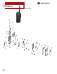
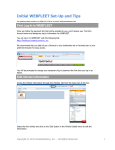
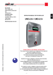
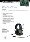
`
Version 01-02
LC828 Professional Portable RadioModule Manual©
LC828 Ruggedized professional Radio Manual
Page 1 of 13
Table of Contents:
1
SUMMARY: .............................................................................. 3
2
INTRODUCTION: ..................................................................... 4
2.1 ASSOCIATED PROPRIETY DOCUMENTATION: .......................................... 4
2.2 SUPPORTED PORTABLE RADIOS: ........................................................ 4
2.3 PUBLICATION RECORD: .................................................................. 4
2.4 ALERT NOTICES:.......................................................................... 5
2.5 CONTACT DETAILS: ....................................................................... 5
2.6 COPYRIGHT: ............................................................................... 5
2.7 ABBREVIATIONS ........................................................................... 6
2.8 MODEL-CHART: ........................................................................... 7
2.9 SPECIFICATIONS: ......................................................................... 7
2.9.1 Transmitter: ...................................................................... 7
2.9.2 Receiver: ........................................................................... 7
2.9.3 DC-Power: ......................................................................... 8
2.9.4 DC-DC converter Power specifications: .................................. 8
3
TECHNICAL OUTLINE: ............................................................. 9
3.1 CONTROLS: ................................................................................ 9
3.2 CONNECTORS: .......................................................................... 10
3.2.1 RF-CONNECTOR: .................................................................... 11
3.2 LED: ..................................................................................... 12
3.2 CHANNEL CHANGE: ..................................................................... 13
5.0 DIMENSIONS: ........................................................................13
LC828 Ruggedized professional Radio Manual
Page 2 of 13
1
Summary:
The LC828 Radio-Module is a modified MOTOROLA Professional
Portable Radio under control of a Rotronix Ltd. PROIS interfaceboard (IOB151208).
The standard operation voltage is 7.5 Volt. Adding a optional
custom-made switch-mode power-supply will change the operation
voltage from 11 to 28 Volts.
Provision is made on the PROIS Interface-board for additional
option-boards, e.g. a multi-frequency CTCSS board.
Features not found in the standard radio are:
Adjustable Transmit hang timer.
Low battery voltage alarm utilizing a DTMF tone on the tail of
the transmitter.
Special scan.
Linking option.
One-wire TX/RX audio.
Flat TX/RX (selectable).
Interface
Option Board
Professional
Portable Radio
PROIS
connector
9-pin D-shell
connector
Portable Radio with PSU and PROIS option
board in die-cast housing
LC828 Ruggedized professional Radio Manual
Page 3 of 13
2
Introduction:
This manual provides information about the LC828 radio-module.
The LC828 radio-module is based on a modified Motorola
Professional Portable Radio, with a PROIS interface-module (Part No:
1202899J28) and a power-supply all mounted in a die-cast housing.
This makes a universal low current transmit/receive module
compliant with most regulatory acceptance requirements.
The radio utilizes the Analogue Frequency Modulation Scheme.
2.1 Associated Propriety Documentation:
Motorola service manual: (Part No: 6804110J64-H)
Motorola PROIS 2.03 Manual
Motorola PROIS 2.03 Electrical Manual: (Part No: 1202899J28)
Rotronix Ltd DC-DC converter manual (Part No: PSU-322859©)
Rotronix Ltd LC828 interface-module Manual (Part No: RTRNX-GP328V4)
Rotronix Ltd Professional Portable Radio Interface Option-Board
Manual (Part No: IOB151208) ©
2.2 Supported Portable Radios:
PRO5150, PRO5350, GP140, GP318, GP328, GP328 LS,
HT750, HT750.LS, MTX850LS, HT1250, HT1250.LS+,
MTX8250LS, PRO7150, PRO7350, GP338, GP338 LS,
PRO9150, HT1550XLS
2.3 Publication Record:
Issue
Publication Date
Author
Description
1.01
January 2009
Hans de Roode
First issue
LC828 Ruggedized professional Radio Manual
Page 4 of 13
2.4 Alert Notices:
Within this manual, four types of alerts are given to the reader:
warning, caution, important and note. The following paragraphs
illustrate each type of alert and its associated symbol.
Warning!!
This alert indicates a potential risk of death or serious injury.
Caution
This alert indicates a risk of minor or moderate injury to
people.
Important
This alert indicates the risk of equipment damage or
malfunction.
Note
This alert highlights information that is required to ensure
that procedures are performed correctly.
2.5 Contact details:
Rotronix Ltd
135 Darnley Road
RD3 Amberley, New Zealand
Commercial e-mail:
[email protected]
Technical e-mail:
[email protected]
2.6 Copyright:
Copyright protects original works, regardless of whether the
work is published or unpublished. Under the Copyright Act
1994, copyright automatically applies as soon as the work is
put into material form – whether in print, stored on computer
or recorded in some way. New Zealand is a signatory to the
Berne convention, and therefore New Zealand protects the
rights of copyright owners from other countries in the same
way it does for our own copyright owners. It is unlawful to
copy all or part of this manual without a license or without
approval from the copyright owner, unless there is a statutory
exception to such infringement.
LC828 Ruggedized professional Radio Manual
Page 5 of 13
2.7 Abbreviations
Abbreviation
Description
3DK
ASCII
Third-Party Developer’s Kit
American Standard Code for Information Interchange
AVL
Automatic Vehicle Location
CCRI
Computer Controlled Radio Interface
CRC
Cyclic Redundancy Check
CTCSS
Continuous Tone Coded Squelch System
CTS
Clear to Send
DCE
Data Circuit-Terminating Equipment
DCS
Data Carrier System
DTE
Data Terminal Equipment
DTMF
Dual Tone Multi-Frequency
FEC
Forward Error Correction
FFSK
Fast Frequency Shift Keying
GPIO
General Purpose Input/Output
IPN
Internal Part Number
LED
Light-Emitting Diode
MSD
Most Significant Digit
MPPR
IOB
Motorola Professional Portable Radio
National Marine Electronics Association standard.
Combined electrical and data specification for
communication between marine electronics and GPS
receivers.
Interface
Option Board
PC
Personal Computer
PTT
Press To Talk
PCB
RTS
Printed Circuit Board
Motorola proprietary Professional Radio Option
Interface Specification
Recommended Minimum sentence C. NMEA GPS
message type for the minimum recommended
transmit/GPS
data.
Request to Send
NMEA
PROIS
RMC
Rx
Receive mode
RXD
Receive Data
SDM
Short Data Message
SMC
Switched Mode Converter (12 to 7.5V)
TX
Transmit mode
TXD
Transmit Data
UART
Universal Asynchronous Receiver-Transmitter
XON
Data Transmitter On
XOFF
Data Transmitter Off
ZIF
Zero Insertion Force Connector
LC828 Ruggedized professional Radio Manual
Page 6 of 13
2.8 Model-Chart:
Radio-Module Model:
Frequency-Range
LC828/VHF-low 4/10
4 or 10 channels within 136 – 160 MHz
LC828/VHF-high 4/10
4 or 10 channels within 150 – 179 MHz
LC828/UHF-low 4/10
4 or 10 channels within 403 – 470 MHz
LC828/UHF-high 4/10
4 or 10 channels within 470 – 520 MHz
Other models are available on request.
2.9 Specifications:
The VHF radios have been tested and approved under the following BaseStation standards:
Euro, includes EM Compliance testing.
FCC
Australian Standards 2945
The UHF radios are pending approval.
2.9.1 TRANSMITTER:
Freq. Stability (-30°C to +60°C):
VHF TX power:
UHF TX power:
Channel bandwidth:
Transmit-audio level
Spurs/Harmonics:
FM Noise:
2.9.2 RECEIVER:
Sensitivity
Receive-audio level
Selectivity
Intermodulation
Spur Rejection:
Image Rejection:
0.00025%.
5 Watt adjustable.
4 Watt adjustable.
12.5, 20 or 25 KHz.
0 dBm for full system deviation.
(adjustable).
-36 dBm < 1 GHz.
-30 dBm > 1 GHz.
-40 dB.
12dB EIA SINAD: 0.35 μV.
0 dBm.
Adjacent Channel Selectivity ETS -60 dB.
ETS -65 dB.
-70 dB.
-70 dB.
LC828 Ruggedized professional Radio Manual
Page 7 of 13
2.9.3 DC-POWER:
Without the DC-DC power supply (Part No: PSU-322859©), the LC828
radio module works on 7.5 Volt, (+/- 20%) the stand-by current is
50 mA. Transmit current (full TX power) 1.7 Amp.
If the radio is used for receive only, than the radio can be powered
with the 7.5Volts from the option-board which is derived from the
Transmit radio.
2.9.4 DC-DC CONVERTER POWER SPECIFICATIONS:
The LC828 module draws the following currents with the DC-DC
converter fitted:
Input Voltage Current RX (mA) Current TX (A)
11
12
13
14
15
16
17
18
19
20
21
22
13
24
25
26
27
28
54
51.7
48
47
45
44
43
42
41
40
37
35.4
34
33.5
32
31
30
29.6
LC828 Ruggedized professional Radio Manual
1.3
1.2
1.1
1
0.96
0.91
0.86
0.82
0.77
0.73
0.70
0.67
0.65
0.63
0.62
0.58
0.57
0.55
Current Repeater
RX (mA) + LED
113
106
99
95
92
90
87.5
86
85
78
74
72
68
66.4
65
63
62.5
62
Page 8 of 13
3
Technical outline:
3.1 controls:
The IOB has three adjustable potentiometers:
1
VR1, sets the TX-tail, (0 to 2 sec).
2
VR2, Audio output-level (replaced with 0 ohm resistor).
3
VR3, Audio input-level (TX audio).
LC828 Ruggedized professional Radio Manual
Page 9 of 13
3.2 Connectors:
The Main Connector (J3) is of the type D-shell, 9 pin plug.
Pin:
Description:
1
2
3
4
5
6
7
8
9
shell
GND
7.5V (max. 500mA out)
RX/TX audio
3.3V (reference)
Channel select input
PTT
RX busy out
Power supply
Power supply
GND
LC828 Ruggedized professional Radio Manual
Page 10 of 13
3.2.1
RF-Connector:
The antenna-connector is of the type SMA socket, and has an
impedance of 50 ohm.
LC828 Ruggedized professional Radio Manual
Page 11 of 13
3.2 LED:
The LC828 uses the standard radio LED, brought to the outside of
the die-cast box by a light-tunnel.
Modifying the LED functions is done trough the radio CPS.
The LED indicates the following:
Event:
LED
Indication
switch-on:
Green flash
Red flash
OK
Radio Error
Receiving:
Flashing Red Invalid CTCSS
Green
Solid Red
Transmitting:
Flashing Red
Stand-by
Solid Green
LC828 Ruggedized professional Radio Manual
valid signal
transmitting
low battery
scanning
Page 12 of 13
3.2 Channel change:
A voltage on J3.5 will select a channel. The voltage can be in the
range of 0 to 3.3 Volts (reference is J3.4). Channel selection is
according to the following table:
Channel selected: Voltage J3.5:
1
2
3
4
5
6
7
8
9
10
4
3.3
3
2.7
2.4
2.1
1.8
1.5
1.2
0.9
0.6
0
5.0 Dimensions:
Width mm:
Height mm:
Depth mm:
Material:
150
64
36
Enclosure and lid made from cast-aluminum,
lid with neoprene cord seal.
Surface finish:
Powder coated in RAL 7001
Weight:
475 grams.
Mounting holes are under the lid, diameter 5mm.
LC828 Ruggedized professional Radio Manual
Page 13 of 13