1
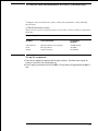
Testing Performance
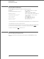
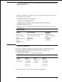
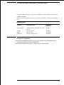
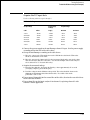
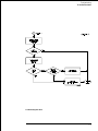
Perform an operational accuracy calibration
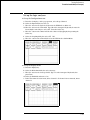
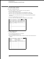
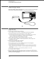
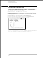
Acquire the data
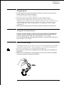
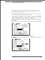
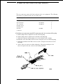
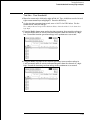
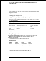
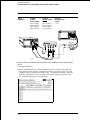
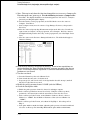
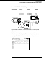
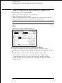
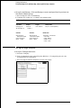
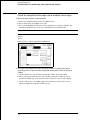
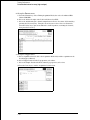
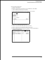
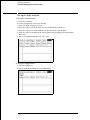
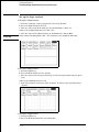
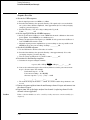
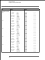
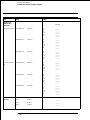
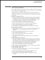
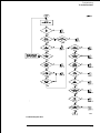
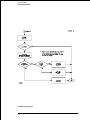
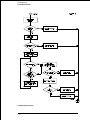
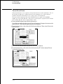
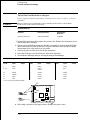
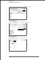
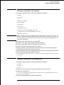
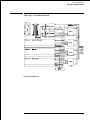
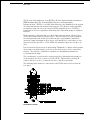
1 Press the RUN key. The clicking of attenuator relays should be audible. Verify
2
3
4
5
6
7
8
See Also
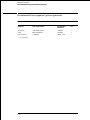
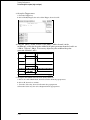
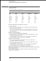
resistance readings on the digital multimeter of 50 Ω ± 0.5 Ω (49.5 to 50.5 Ω). Record
the reading in the performance test record.
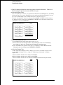
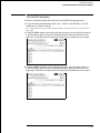
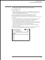
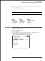
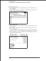
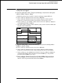
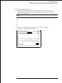
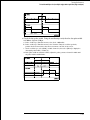
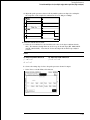
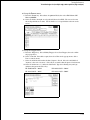
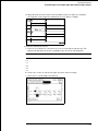
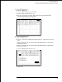
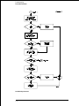
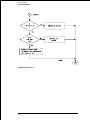
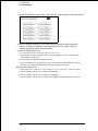
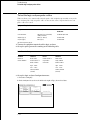
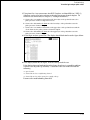
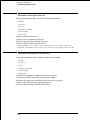
In the Channel menu change the Coupling field to 1MΩ / DC. The clicking of
attenuator relays should be audible.
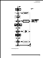
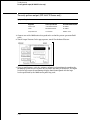
Press the RUN key. Verify resistance readings on the digital multimeter of 1 MΩ ±
10 kΩ (0.990 to 1.010 MΩ). Record the reading in the performance test record.
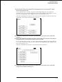
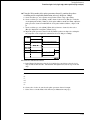
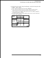
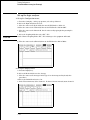
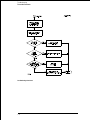
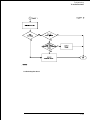
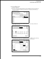
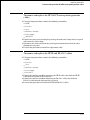
In the Channel menu change the Coupling field to 50 Ω/DC and V/Div to 200 mV/Div.
Repeat steps 1 through 3.
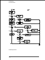
In the Channel menu change the Coupling field to 50 Ω /DC and V/Div to 1 V/Div.
Repeat steps 1 through 3.
In the Channel menu change the Coupling field to 50 Ω /DC and V/Div to 4 V/Div.
Repeat steps 1 through 3.
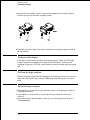
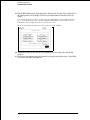
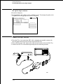
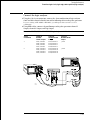
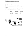
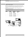
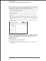
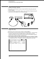
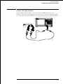
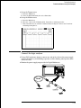
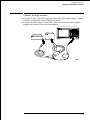
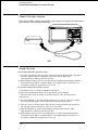
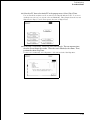
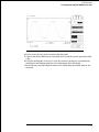
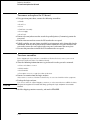
Connect the male end of the BNC tee to the channel 2 input of the oscilloscope
module.
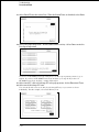
Repeat from "Set up the logic analyzer" for channel 2, replacing channel 1 with
channel 2 where applicable.
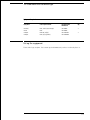
If a reading is not within limits, then the attenuator for the out-of-bounds channel should be
replaced (see chapter 6).
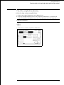
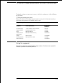
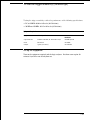
Perform an operational accuracy calibration
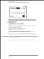
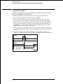
At this point, an operational accuracy calibration should be performed. Follow the
procedure "To calibrate the oscilloscope" in chapter 4, "To calibrate the oscilloscope."
3–72