1
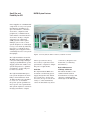
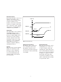
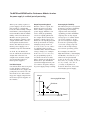
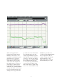
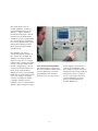
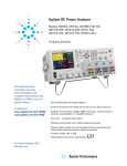
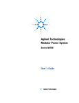
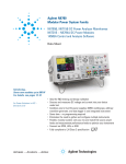
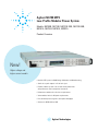
Agilent N6700 MPS
Low-Profile Modular Power System
Models: N6700B, N6710B, N6731B-36B, N6741B-46B,
N6751A, N6752A, N6761A, N6762A
Product Overview
New!
Higher voltage and
higher current models
• Ideal for ATE systems in R&D, Design Validation, and Manufacturing
• Small size: up to 4 outputs in 1U of rack space
• Flexible, modular system: Can mix and match power levels
and performance levels to optimize investment
• Performance modules for critical test requirements
• Value modules for basic DC power requirements
• Fast command processing times to improve throughput
• Connect via GPIB, LAN, or USB
Agilent Technologies
Small Size and
Flexibility for ATE
Power supplies are a fundamental
component of every test system
in industries including aerospace and defense, consumer
electronics, computers and
peripherals, communications,
semiconductor and automotive
electronics. Today’s complex
automatic test equipment
(ATE) systems often require
multiple power sources. Test
system designers are challenged
to keep costs down by reducing
rack space occupied by these
multiple power supplies and to
continually increase test system
throughput.
The Agilent N6700 Low-Profile
Modular Power System (MPS) is
a 1U (rack unit) high, multipleoutput programmable DC power
supply system that enables test
system integrators to optimize
performance, power and price
to match test needs.
The Agilent N6700 MPS gives
test system designers the flexibility to mix and match from
16 different DC power modules
to create a 1- to 4-channel
DC power system optimized to
meet specific test requirements.
Test system engineers can invest
in high-performance outputs
N6700 System Features
Figure 1. Connectivity: GPIB, 10/100 Base-T Ethernet, and USB 2.0 all standard
where speed and accuracy
are needed, or purchase basic
performance outputs for simple
DC power requirements.
Small Size
The Agilent N6700 MPS uses
an advanced switching power
supply design that fits within
1U of rack space. It has side
air vents (no top or bottom air
vents) so other instruments
can be mounted directly above
2
or below it. (Requires rack
mount kit; see Ordering
Information.)
Built-in Measurement
of Voltage and Current
The N6700 modules come
standard with built-in
measurement of voltage and
current to simplify wiring
and design of an ATE system.
Protection Features
Each N6700 module is protected
against over-voltage, overcurrent, and over-temperature.
A fault condition in one
module can be detected within
10 microseconds by other modules so that they can be quickly
shut down to avoid hazardous
conditions on your DUT.
Output on
V1
Module 1
V2
Delay 2
Connectivity
The N6700 MPS comes standard
with GPIB, USB 2.0, and
10/100 Base-T Ethernet LAN
interfaces. While GPIB is best
suited for use with existing
systems, Agilent offers USB
and LAN to allow you to take
advantage of the availability,
speed, and ease-of-use of
common computer industry
standard interfaces.
Security
When used in systems running
GPIB, the LAN and/or USB
interfaces can be disabled
for extra security. Also, all
non-volatile RAM data and
settings can be cleared from
the front panel.
V3
Module 2
Module 3
Delay 3
Figure 2. Output Sequencing
Control from any Browser
The N6700 can be controlled
via a standard web browser.
The N6700 contains a web
server that provides web pages
for monitor, control, and setup
of the MPS.
3
Output Sequencing
Each DC power module can be
individually set to turn on or
to turn off with a delay. By
adjusting the delay times and
then commanding the N6700 to
turn on, you can set the N6700
modules to sequence on in a
particular order. The same
sequencing capability is available to shut down the modules
in a particular order.
Programmable Voltage Slew
For some applications, like
inrush limiting or powering
rate-sensitive devices, it is
necessary to slow down and
control the speed of the power
supply to maintain a specific
voltage slew rate. The N6700
provides programmable voltage
slew rate, so that with a single
command, you can generate a
0 V to full-scale voltage change
controllable from 1 millisecond
to 10 seconds. Programmable
voltage slew is available from
the front panel when operating
the N6700 manually or via
computer control.
Series Operation
To increase available voltage
and power, similarly rated
outputs can be operated
directly in series.
Easy Parallel Operation
with Virtual Channels
To increase available output
power and current, identical
outputs can be operated in
parallel. To simplify parallel
operation for applications
requiring currents greater
than any single output can
provide, the N6700 offers
virtual channels, a firmwarebased feature that allows
the N6700 system to treat
up to 4 channels as a single,
synchronized channel. Once
configured, all functions
(sourcing, measurements,
triggering, protection, and
status monitoring) behave
as if there is 1 channel of
up to 4 times the capacity
of a single channel, without
writing a single line of code
to manage the interaction
and synchronization of the
paralleled power supplies.
Virtual channel capability is
available from the front panel
when operating the N6700
manually or via computer
control.
4
Triggering
The N6700B Low-Profile
MPS mainframe has hardware
trigger in/trigger out signals
which permit the N6700 to be
synchronized with external
events. For example, a switch
closure in the fixture can trigger
the N6700 to turn on power
to the DUT, or change voltage,
or take a measurement.
Drivers
The N6700 comes with both
VXIplug&play drivers and
IVI-COM drivers.
Programming Language
The N6700 supports SCPI
(Standard Commands for
Programmable Instruments).
Output Disconnect Relays
Each module in the N6700
can be individually ordered
with optional Output Disconnect
Relays. These relays disconnect
both the plus and minus side
of the power supply, including
the sense leads.
Figure 3. Front panel with up to 4 channels displayed simultaneously (Picture shows 3 channels installed.)
Figure 4. Rear panel (Picture shows 3 channels installed.)
Front Panel
In addition to full control over
its three standard interfaces, the
N6700 has a full featured front
panel to permit easy manual
operation for test prototyping,
debugging, and troubleshooting
when used in an ATE system.
You can have confidence that
the N6700 is working properly
because you can view the
settings and actual output
values on all four outputs at
the same time.
Universal AC Input
The N6700 has a universal input
that operates from 100-240 Vac,
50/60/400 Hz. There are no
switches to set or fuses to
change when switching from
one voltage standard to another.
The AC input employs power
factor correction.
Quick Disconnects
Each power module has quick
disconnects for easy system
setup and maintenance.
Rack Mount Kit
The N6700 is easily rack-mounted
using available option #908.
This kit provides all the necessary hardware to rack mount
one N6700B mainframe in only
1U of rack space. This rack
mount kit includes front rack
ears and rear supports which
take the place of standard rack
rails and/or slides. Note that
standard rack rails or slides
are not needed and are not
compatible with the N6700B
because of its 1U size and
airflow requirements.
Figure 5. Quick disconnects for power and sense leads
5
Choosing the right DC Power
Modules to meet your ATE needs
measurement accuracy when
viewing high-speed transient or
pulse events within the deviceunder-test (DUT). In addition,
autoranging output capabilities
enable one power supply to do
the job of several traditional
power supplies.
N6730/40 Family
For basic DC applications
N6750 Family
For applications where
the power supply plays a
critical role
The Agilent N6750 family of
high-performance, autoranging
DC power modules provides
low noise, high accuracy and
programming speeds that are
up to 10 to 50 times faster than
other programmable power
supplies. In addition, Agilent
has, for the first time, included
high-speed test extensions in
general-purpose power supplies.
The high-speed test extensions
offer an oscilloscope-like
digitizer that simplifies system
configuration and increases
N6760 Family
For applications where
precision is required
The Agilent N6730 and N6740
families of DC power modules
provide programmable voltage
and current, measurement and
protection features at a very
economical price, making these
modules suitable to power the
DUT or to provide power for
ATE system resources, such
as fixture control.
The Agilent N6760 family of
precision DC power modules
provides precise control
and measurements in the
milliampere and microampere
region with the ability to
simultaneously digitize
voltage and current,
and capture those
measurements in
an oscilloscope-like
data buffer.
Figure 6. User re-configurable
modular system
6
The N6750 and N6760 Families: Performance Modules for when
the power supply is a critical part of your testing
When your testing requires a
power supply to do more than
just provide a constant DC
level, the N6750 family of HighPerformance, Autoranging DC
Power Modules and the N6760
family of Precision DC Power
Modules are the perfect fit.
These modules combine a fast
output with flexible controls
and sophisticated measurements. The N6750/60 is more
than a power supply; it is a
stimulus/response instrument.
To fit in 1U, the N6750/60
use an advanced switch-mode
design that offers the low
output noise and fast output
speed typically found on
linear power supplies.
Low Noise Outputs
Careful attention has been paid
to this design to ensure low
normal mode noise (ripple and
peak-peak) as well as low common mode noise. This switching power supply outperforms
most linear power supplies on
the market.
Output Programming Speed
When it comes to speed, the
N6750/60 achieves performance unlike a typical DC
power supply. Thanks to an
active down-programming
circuit to rapidly pull down
the output when lowering the
module’s output voltage, the
N6750/60 can rapidly program
both up and down in voltage.
Changing voltage from 0 V
to 50 V, or 50 V to 0 V, can be
accomplished in less than
5 milliseconds. And for smaller
voltage changes, for example
from 0 V to 5 V or 5 V to 0 V,
the programming speed is
less than 500 microseconds.
These output speeds allow the
N6750/60 to give maximum
system throughput when your
test calls for frequent changes
in power supply voltage settings.
Autoranging for Flexibility
The N6750/60 gives test system
designers even more flexibility
by providing autoranging
outputs. This autoranging
capability provides maximum
output power at any output
voltage up to 50 V. This allows
one power supply to do the
job of several power supplies
because its operating range
covers low voltage, high current as well as high voltage,
low current operating points.
For example, the N6751A
High-Performance, Autoranging
DC Module, rated at 50 V, 5 A,
and 50 W can provide full
power at 10 V @ 5 A (=50 W),
20 V @ 2.5 A (= 50 W), 33.3 V @
1.5 A (= 50 W), 50 V @ 1 A
(= 50 W) or anywhere in
between. Therefore, this 50 W
autoranging power supply,
Voltage
Autoranging 50 W Output
50 V
50 W Curve
10 V
0
1A
5A
7
Current
due to its extended voltage
and current range, can produce
voltage and current combinations in the range of a 250 W
non-autoranging power supply.
Voltage
The flexibility of autoranging is
useful when the DUT operates
over a wide range of voltages,
when the ATE system needs to
test a wide range of DUTs, or
when margin is needed because
the ATE power supply must
be selected before final DUT
power requirements are
determined.
High-Speed Test Extensions
To make your testing go even
faster, the N6750/60 offer
High-Speed Test Extensions
(HSTE). This enhancement to
the N6750/60 DC Power Modules
extends the capabilities to
include features similar to
a built-in arbitrary waveform
generator and a built-in
oscilloscope.
Through the LIST mode of
HSTE, you can download up
to 512 setpoints of voltage and
current. In LIST mode, you can
program the output to execute
a LIST of voltage and current
setpoints. For each setpoint, a
Time in seconds
Figure 7. High Speed Test Extensions LIST mode provides “power ARB” capability
dwell time can be specified and
the power supply will stay (i.e.,
dwell) at that setpoint for the
programmed dwell time value.
For each setpoint in the LIST,
you can have a different dwell
time from 0 to 262 seconds
with 1 microsecond resolution.*
Then, you can trigger the module to begin executing the list.
The module will step thru the
list, staying at each setpoint
for the programmed dwell time,
and then it will move on to the
next point. This speeds up
execution by removing the
computer I/O from the process.
8
The result is an output that
automatically changes according
to the programmed list, just
like an arbitrary waveform
generator.
* Note that the output response
time is less than 5 milliseconds per voltage change,
so steps of less than 5 milliseconds will not achieve
their final output voltage
value before moving on to
the next step. This is useful
when trying to create a
smooth waveform.
Figure 8. High Speed Test Extensions Digitizer adds “oscilloscope-like” data capture
While some applications
require fast risetime and/or
falltimes, some devices can
actually be harmed by a power
supply that is too fast. For
these cases, the LIST mode
of the N6700 can be used to
“slow down” the output. For
this application, you create a
slow ramp of output voltage
by dividing the total voltage
excursion into a smaller number
of steps and dwell at each step
for some amount of time. For
example, let’s say you need to
go from 0 V to 50 V in 500 milliseconds. For this case, the
output programming response
time specification of 5 milliseconds is too fast. To slow down
the output, you could use LIST
mode and program 50 steps
of 1 volt per step, and dwell at
each step for 10 milliseconds.
The result will be a ramp from
0 V to 50 V in 500 milliseconds.
9
HSTE also provides an
oscilloscope-like digitizer built
into the power module to
capture voltage and current
measurements of up to
4096 points at up to 50,000
measurements per second.
For applications such as
design validation of battery
powered digital devices, the
ability to capture dynamic
information about the current
flowing into the DUT allows
designers to better understand
the current drain on DUT batteries and optimize DUT power
management during normal
DUT operation and in DUT
standby mode.
The digitizer can also be
synchronized with changes in
the output. For example, the
digitizer can make measurements in response to a trigger
generated by a change in output
voltage caused by LIST mode.
In this configuration, you can
ensure that measurements are
made at the right moment
during each step of an executing
LIST. This is particularly useful
if you are trying to measure
current consumption during
a rapidly changing voltage
stimulus, such as current drawn
during a pulsed output voltage.
Precision Low-level Performance
The N6760 family of Precision
DC Power Modules additionally
provide dual ranges on both
programming and measurement. In the low range, these
10
power supplies provide precision in the milliampere and
microampere regions. They are
ideally suited for semiconductor
and passive device testing, or
where a precisely controlled
output and highly accurate,
precise measurements are
needed during test.
If you are using Agilent
Multiple-Output System
DC Power Supplies Now
The N6730 and N6740 Families: Basic Modules
when you just need a simple power supply
Models
Not all applications require
high performance power
supplies. When your budget
is tight, and when speed and
accuracy are a low consideration, the Agilent N6700 LowProfile MPS supports basic
DC power modules that provide
an economical solution. The
N6730 and N6740 families give
you clean, reliable DC power
without advanced features.
6621A, 6622A, 6623A,
6624A, 6625A, 6626A,
6627A, 6628A, 6629A
If you would like to take advantage
of the size and speed of the N6700,
and need assistance in converting
from Agilent 662x to the N6700,
please refer to “Application
Note 1467– How to use the
Agilent N67xxA Modular
Power System to replace an
Agilent 662xA”. Look for literature
part number 5989-0466EN
at www.agilent.com/find/N6700
The Agilent N6730 family of
50 W DC Power Modules and
the N6740 family of 100 W DC
Power Modules provide the
following:
• Fully programmable
Constant Voltage/Constant
Current DC Source
• Remote sensing for
accurate control of output
voltage when voltage drops
in the leads are present
• Built-in measurements
of voltage and current
• Protection (over-voltage
over-current, and overtemperature) against
damage to your DUT or
to the power module
11
• Performance (programming
accuracy, measurement
accuracy, noise) suitable
for most common DC power
applications
• Built-in optional output
disconnect relays, which
break both the power and
the sense leads, to simplify
system wiring
Use the N6730/40 in Place of
Fixed-output DC Power Supplies
Many ATE systems have
complex fixtures that contain
indicator lights, relays or
active circuits (like sensors,
triggers, amplifiers) to facilitate
testing of the DUT. These
circuits need DC power, too.
One solution for powering
these ATE system resources
would be to purchase a fixedoutput DC source. However,
there are considerations when
integrating a fixed output
DC source into an ATE system.
The table below illustrates
these points and how it may
be easier, faster, and more
economical to purchase an
N6730/40 programmable DC
Power Module in place of a
fixed-output DC Power Supply.
All the benefits of the
N6700 MPS at a low price
While the N6730/40 are
economical solutions to basic
DC power requirements, they
are also part of the N6700
MPS. Therefore, while saving,
you still have the benefits of:
Factor
Consideration When Using a
Fixed-Output DC Power Supply
Solution Using N6730/40
DC Power Modules in N6700 MPS
Control the
output
You may want some limited control
over this DC source (on/off).
The N6730/40 is fully controllable
over LAN, USB, GPIB
Monitor the
output
You may want to be able to monitor
the voltage or current to ensure proper
operation, which would require wiring
to a system DMM.
The N6730/40 has built-in measurements
of voltage and current, eliminating the
need for wiring to a system DMM.
Mounting
the power
supply
You will need to mount the power
supply in the ATE system. Finding a
safe location can be a challenge. Some
system designers will build a “drawer”
or “tray” for holding power supplies.
However, this adds extra design time,
fabrication costs, installation costs,
and occupies rack space.
The N6730/40 are compact modules
integrated into a 1U rack mountable
mainframe. There is no need to design
or build any custom mounting hardware.
Safety
You may want to provide a safety
interlock to this DC source. This
would require control (on/off) and a
means to detect the interlock condition.
The N6730/40 have hardware inputs
for remote on/off that can be directly
connected to a safety interlock system.
• Small size (true 1U)
• Mix-and-match with other
N6700 DC Power Modules
when you need performance
along with basic DC outputs
• Connectivity via LAN,
USB, and GPIB
• Fast command processing
time of less than 1 ms
• Remote control over internet
via standard web browser
• Friendly front panel
• Optional output
disconnect relays
12
Performance Specifications
Unless otherwise noted, specifications are warranted over the ambient temperature range of 0 to 55°C, and derated above 40°C.
N6751A / N6752A
N6761A / N6762A
50 V
5 A / 10 A
50 W / 100 W
50 V
1.5 A / 3 A
50 W / 100 W
CV peak-to-peak 1
CV rms
6 mV
1 mV
6 mV
1 mV
Voltage
Current
2 mV
2 mA
0.5 mV
30 µA
Voltage
Current
1 mV
1 mA
1 mV
30 µA
Voltage high range
Voltage low range (≤ 5.5 V)
Current high range
Current low range (≤ 100 mA, @ 0 - 7 V) NOTE 2
(≤ 100 mA, @ 0 - 50 V)
0.06% + 19 mV
N/A
0.1% + 20 mA
N/A
N/A
0.016% + 6 mV
0.015% + 1.5 mV
0.04% + 200 µA
0.04% + 15 µA
0.04% + 55 µA
Voltage high range
Voltage low range (≤ 5.5 V)
Current high range
Current low range (≤ 100 mA, @ 0 - 7 V) NOTE 2
(≤ 100 mA, @ 0 - 50 V)
0.05% + 20 mV
N/A
0.1% + 4 mA
N/A
N/A
0.016% + 6 mV
0.016% + 1.5 mV
0.03% + 200 µA
0.03% + 15 µA NOTE 3
0.03% + 55 µA
Voltage settling band
Time
± 75 mV
< 100 µs
DC Output Ratings
Voltage
Current
Power
Output Ripple
and Noise (PARD)
(from 20 Hz – 20 MHz)
Load Effect
(Regulation)
(for any output load change,
with a maximum load-lead
drop of 1 V per lead)
Source Effect
(Regulation)
Programming
Accuracy
(at 23°C ±5°C
after 30 minute
warm-up. Applies
from min. to max.
programming range)
Measurement
Accuracy
(at 23°C ±5°C)
Load Transient
Recovery Time
(time to recover to within the settling band following a load change)
• from 60% to 100% and from 100% to 60% of full load for models N6751A & N6761A
• from 50% to 100% and from 100% to 50% of full load for models N6752A & N6762A.
1 For typical values, refer to Supplemental Characteristics.
2 Requires a 3 minute wait if you have entered the 0- 7 V range from a voltage greater than 7 V..
3 Applies when measuring 4006 data points (SENSe:SWEep:POINts = 4096).
13
± 75 mV
< 150 µs
Performance Specifications (Continued)
Unless otherwise noted, specifications are warranted over the ambient temperature range of 0 to 55°C, and derated above 40°C.
N6731B/
N6741B
N6732B/
N6742B
N6733B/
N6743B
N6734B/
N6744B
N6735B/
N6745B
N6736B/
N6746B
5V
10 A / 20 A
50 W / 100 W
8V
6.25 A / 12.5 A
50 W / 100 W
20 V
2.5 A / 5 A
50 W / 100 W
35 V
1.5 A / 3 A
50 W / 100 W
60 V
0.8 A / 1.6 A
50 W / 100 W
100 V
0.5 A / 1A
50 W / 100 W
10 mV / 11 mV
2 mV
12 mV
2 mV
14 mV
3 mV
15 mV
5 mV
25 mV
9 mV
30 mV
18 mV
Voltage
Current
4 mV
2 mA
4 mV
2 mA
4 mV
2 mA
5 mV
2 mA
5 mV
2 mA
5 mV
2 mA
Voltage
Current
1 mV
1 mA
2 mV
1 mA
2 mV
1 mA
4 mV
1 mA
6 mV
1 mA
10 mV
1 mA
Voltage
Current
0.1% + 19 mV
0.15% + 20 mA
0.1% + 19 mV
0.15% + 20 mA
0.1% + 20 mV
0.15% + 20 mA
0.1% + 35 mV
0.15% + 20 mA
0.1% + 60 mV
0.15% + 20 mA
0.1% + 100 mV
0.15% + 10 mA
Voltage
Current
0.1% + 20 mV
0.15% + 20 mA
0.1% + 20 mV
0.15% + 10 mA
0.1% + 20 mV
0.15% + 5 mA
0.1% + 35 mV
0.15% + 4 mA
0.1% + 60 mV
0.15% + 4 mA
0.1% + 100 mV
0.15% + 2 mA
± 200 mV / 300 mV
200 µs
± 200 mV / 300 mV ± 400 mV / 500 mV ± 500 mV / 1000 mV
200 µs
200 µs
200 µs
DC Output Ratings
Voltage
Current
Power
Output Ripple
and Noise (PARD)
(from 20 Hz – 20 MHz)
CV peak-to-peak
CV rms
Load Effect
(Regulation) 1
Source Effect
(Regulation)
Programming
Accuracy 2
(at 23°C ±5°C
after a 30 minute
warm-up)
Measurement
Accuracy
(at 23°C ±5°C)
Load Transient
Recovery Time
(time to recover to within the settling band following a load
change from 50% to 100% and from 100% to 50% of full load.)
Voltage settling band
Time
± 80 mV / 100 mV
200 µs
± 80 mV / 100 mV
200 µs
1 With an output change from no load to full load, up tp a maximum load-lead drop of 1 V per lead.
2 Applies from minimum to maximum programming range. (see Supplemental Characteristics)
14
Supplemental Characteristics
Supplemental characteristics are not warranted but are descriptions of performance determined either by design or type testing.
All characteristics are typical unless otherwise noted.
N6751A / N6752A
N6761A / N6762A
Voltage high range
Voltage low range (≤ 5.5 V)
Current high range
Current low range (≤ 0.1 A)
20 mV – 51 V
N/A
10 mA – 5.1 A/10 mA – 10.2 A
N/A
15 mV – 51 V
12 mV – 5.5 V
1 mA – 1.53 A/1 mA – 3.06 A
0.1 mA – 0.1 A
Voltage high range
Voltage low range (≤ 5.5 V)
Current high range
Current low range (≤ 0.1 A)
3.5 mV
N/A
3.25 mA
N/A
880 µV
90 µV
60 µA
2 µA
Voltage high range
Voltage low range (≤ 5.5 V)
Current high range
Current low range (≤ 0.1 A)
1.8 mV
N/A
410 µA
N/A
440 µV
44 µV
30 µA
1 µA
Voltage high range
Voltage low range (≤ 5.5 V)
Current high range
Current low range (≤ 0.1 A)
18 ppm + 160 µV
N/A
100 ppm + 45 µA
N/A
18 ppm + 140 µV
40 ppm + 70 µV
33 ppm + 10 µA
60 ppm + 1.5 µA
Voltage high range
Voltage low range (≤ 5.5 V)
Current high range
Current low range (≤ 0.1 A)
25 ppm + 35 µV
N/A
60 ppm + 3 µA
N/A
23 ppm + 40 µV
30 ppm + 40 µV
40 ppm + 0.3 µA
50 ppm + 0.3 µA
Voltage, from no load to full load
Current, from no load to full load
1 mV
1 mA
0.5 mV
5 µA
Output Ripple and Noise (PARD)
Typical CV peak-to-peak
CC rms
4 mV
2 mA
4 mV
2 mA
500 µA
< 2 mA
500 µA
< 2 mA
Programming Ranges
Programming Resolution
Measurement Resolution
Programming Temperature
Coefficient per °C
Measurement Temperature
Coefficient per °C
Load Cross Regulation
Common Mode Noise
(from either output to chassis)
rms (20 Hz - 20 MHz)
peak-to-peak (20 Hz - 20 MHz)
Over-voltage Protection
Accuracy
Response Time
0.25% + 250 mV
0.25% + 250 mV
50 µs from ocurence of 0V condition to start of output shutdown
Down-programming Capability1
Continuous power
Peak current
7W
7A
1 Modules can discharge a 1000 µF capacitor from 50 V to 0 V at a rate of 4 times/second.
15
7W
3A
Supplemental Characteristics (Continued)
Supplemental characteristics are not warranted but are descriptions of performance determined either by design or type testing.
All characteristics are typical unless otherwise noted.
N6751A / N6752A
N6761A / N6762A
0.2 ms
1.5 ms
0.6 ms
2.2 ms
0.5 ms
4 ms
0.9 ms
4 ms
0.3 ms
1.3 ms
0.3 ms
1.3 ms
0.45 ms
1.4 ms
0.45 ms
1.4 ms
2.1 ms
11 ms
4.5 ms
23 ms
Up-programming Time with full resistive load:
(time from 10% to 90% of total voltage excursion)
Voltage setting from 0 V to 10 V
Voltage setting from 0 V to 50 V
Up-programming Settling Time with full resistive load:
(time from start of voltge change to within 50 mV of final value))
Voltage setting from 0 V to 10 V
Voltage setting from 0 V to 50 V
Down-programming Time with no load:
(time from start of voltage change to output voltage < 0.5 V)
Voltage setting from 10 V to 0 V
Voltage setting from 50 V to 0 V
Down-programming Settling Time with no load:
(time from start of voltage change to output voltage
within 50 mV of final value)
Voltage setting from 10 V to 0 V
Voltage setting from 50 V to 0 V
Down-programming Time with 1000 µF load:
(time from start of voltage change to output voltage < 0.5 V)
Voltage setting from 10 V to 0 V
Voltage setting from 50 V to 0 V
16
Supplemental Characteristics (Continued)
Supplemental characteristics are not warranted but are descriptions of performance determined either by design or type testing.
All characteristics are typical unless otherwise noted.
N6731B/
N6741B
N6732B/
N6742B
N6733B/
N6743B
N6734B/
N6744B
N6735B/
N6745B
N6736B/
N6746B
Voltage
15 mV – 5.1 V
15 mV – 8 .16 V
30 mV – 20.4 V
40 mV – 35.7 V
70 mV – 61 V
100 mV – 102 V
Current
60 mA – 10.2 A/
60 mA – 20.4 A
40 mA – 6.375 A/
40 mA – 12.75 A
10 mA – 2.55 A/
10 mA – 5.1 A
5 mA – 1.53 A/
5 mA – 3.06 A
2.5 mA – 0.85 A/
2.5 mA – 1.7 A
1.5 mA – 0.51 A/
1.5 mA – 1.02 A
Voltage
Current
3.5 mV
7 mA
4 mV
4 mA
7 mV
3 mA
10 mV
2 mA
18 mV
1 mA
28 mV
0.5 mA
Voltage
Current
3 mV
10 mA
4 mV
7 mA
10 mV
3 mA
18 mV
2 mA
30 mV
1 mA
33 mV
0.5 mA
CC rms
8 mA
4 mA
2 mA
2 mA
2 mA
2 mA
1 mA
< 10 mA
1 mA
< 10 mA
1 mA
< 10 mA
1 mA
< 10 mA
1 mA
< 10 mA
1 mA
< 10 mA
0.25% + 300 mV
0.25% + 300 mV
Programming Ranges
Programming Resolution
Measurement Resolution
Output Ripple and
Noise (PARD)
Common Mode Noise
(from either output to chassis)
rms (20 Hz – 20 MHz)
peak-to-peak (20Hz - 20MHz)
Over-voltage Protection
Accuracy (without relay option)
Response Time
0.25% + 250 mV
0.25% + 250 mV
0.25% + 250 mV
0.25% + 250 mV
50 µs from occurence of 0V condition to start of output shutdown
Maximum Up-programming and Down-programming
Time with full resistive load:
(time from 10% to 90% of total voltage excursion)
Voltage setting from 0 V to
full scale and full scale to 0 V
20 ms
20 ms
20 ms
20 ms
20 ms
20 ms
100 ms
100 ms
100 ms
100 ms
100 ms
Maximum Up-programming and Down-programming
Settling Time with full resistive load:
(time from start of voltage change until voltage
settles within 0.1% of the full-scale voltage
of its final value)
Voltage setting from 0 V to
full scale and full scale to 0 V
100 ms
Remote Sense Capability:
Outputs can maintain specifications with up to a 1-volt drop per load lead.
Series and Parallel Operation:
Similarly rated outputs can be operated directly in parallel or can be connected for straight series
operation. Auto-series and auto-parallel operation is not available.
17
Supplemental Characteristics (Continued)
Supplemental characteristics are not warranted but are descriptions of performance determined either by design or type testing.
All characteristics are typical unless otherwise noted.
N6700B MPS Mainframe
Output Response
Characteristics
Command processing time
Protection Response
Characteristics
Inhibit Input
5 µs (from receipt of inhibit to start of shutdown)
Fault on coupled outputs
< 10 µs (from receipt of fault to start of shutdown)
Maximum voltage ratings
+16.5 VDC/-5 VDC between pins (pin 4 is internally connected to chassis ground).
Pins 1 and 2 as FLT output
Maximum low-level output voltage = 0.5 V @ 4 mA
Maximum low-level sink current = 4 mA
Typical high-level leakage current = 0.14 mA @ 16.5 VDC
Pins 1 thru 8 as digital/trigger outputs
(pin 4 = common)
Maximum low-level output voltage = 0.5 V @ 4 mA; 1 V @ 50 mA; 1.75 V @ 100 mA
Maximum low-level sink current = 100 mA
Typical high-level leakage current = 0.12 mA @ 16.5 VDC
Pins 1 thru 8 as digital/trigger inputs
and pin 3 as INH input
(pin 4 = common)
Maximum low-level input voltage = 0.8 V
Minimum high-level input voltage = 2 V
Typical low-level current = 2 mA @ 0 V (internal 2.2k pull-up)
Typical high-level leakage current = 0.12 mA @ 16.5 VDC
Digital Control
Characteristics
≤ 1 ms from receipt of command to start of the output change
Interface Capabilities
GPIB
SCPI - 1993, IEEE 488.2 compliant interface
USB 2.0
Requires Agilent I/O Library version M.01.01.04
10/100 LAN
Requires Agilent I/O Library version L.01.01
Web server
Built-in Web server - requires Internet Explorer 5+ or Netscape 4.x
Environmental Conditions
1Category
Operating environment
Indoor use, installation category II1, pollution degree 2
Temperature range
0˚C to 55˚C (output derated above 40˚C)
Relative humidity
Up to 95%
Altitude
Up to 2000 meters
Storage temperature
-30˚C to 70˚C
II for AC input.
18
Supplemental Characteristics (Continued)
Supplemental characteristics are not warranted but are descriptions of performance determined either by design or type testing.
All characteristics are typical unless otherwise noted.
N6700B MPS Mainframe
Regulatory
Compliance
EMC
Complies with the European EMC directive 89/336/EEC for Class A test and
measurement products.
Complies with the Australian standard and carries the C-Tick mark.
This ISM device complies with Canadian ICES-001.
Cet appareil ISM est conforme à la norme NMB-001 du Canada.
Electrostatic discharges greater than 1 kV near the I/O connectors may cause
the unit to reset and require operator intervention.
Acoustic Noise
Declaration
Safety
Complies with the European Low Voltage Directive 73/23/EEC and carries the CE-marking.
This product also complies with the US and Canadian safety standards for test
and measurement products.
This statement is provided to
comply with the requirements
of the German Sound Emission
Directive, from 18 January 1991.
Sound Pressure Lp < 70 dB(A),
At Operator Position, Normal Operation, According to EN 27779 (Type Test).
Schalldruckpegel Lp <70 dB(A)
Am Arbeitsplatz, Normaler Betrieb, Nach EN 27779 (Typprüfung).
*
*
*
*
*
*
Isolation
No output terminal may be more than 240 VDC from any other terminal or chassis ground.
AC Input
Nominal Input Ratings
100 VAC – 240 VAC; 50/60/400 Hz
Input Range
86 VAC – 264 VAC
Power Consumption
1000 VA typical; 1100 VA maximum (with power factor correction)
Fuse
Internal fuse (not customer accessible)
Mainframe
Dimensions
Height:
44.45 mm; 1.75 in.
Width:
432.5 mm; 17.03 in.
Depth:
596.9 mm; 23.5 in.
With 4 installed modules
Net: 12.78 kg; 28 lbs.
Mainframe
Weight
19
Agilent N67xxA
Option Characteristics
Output Relay Option
Mechanical relays that break
conduction path on + output,
- output, + sense, - sense.
Relays sequenced to ensure
no loss of control when sense
lines are opened.
Autoranging Characteristic
Voltage
Autoranging 50 W Output
50 V
50 W Curve
10 V
High Speed Test Extensions
List mode
• Number of steps = 1 to 512
• Dwell time = 1 µs to 262 seconds
• Maximum list repetitions =
256, or infinite
0
1A
5A
Current
Voltage
Autoranging 100 W Output
High Speed Test Extensions
Digitizer
• Measurement points = 1 to 4096
• Sample rate =
0.000025 Hz to 50 kHz
50 V
100 W Curve
12 V
8.5 V
0
2A
8.33 A 10 A
Current
Voltage
Precision Outputs
50 V
33 V
0
20
1 A 1.5 A – 50 W output
2 A 3 A – 100 W output
Current
Right Side
Outline Diagram
571.5 mm
22.5"
Top of Unit
549.7 mm
21.64"
25.4 mm
1.00"
432.5 mm
17.03"
44.45 mm
1.75"
482.6 mm
19.00"
Agilent Technologies
= Airflow
425.45 mm
16.75"
21
Ordering
Information
The N6700 Modular Power
System is available 2 ways:
(1) You can order an N6700B
mainframe and various
modules as separate
products. (See steps below.)
Each item will arrive in
a separate box such that
you can assemble the
system yourself when
you need to.
Mainframe
N6700B
Low-Profile Modular Power System Mainframe
Holds 1 to 4 modules.
Available options to N6700B
N6700B-908
Rack Mount Kit
Required for rack mounting. Standard rack mount hardware will not work.
This N6700 Rack Mount Kit is also orderable separately as product N6709A
N6700B-FLR
Filler Panel Kit
Required when you have < 4 modules in an N6700B.
Each filler panel kit contains 3 filler panels.
This N6700 Filler Panel Kit is also orderable separately as product N6708A
N6700B-0L1
Standard Documentation Kit
N6700B-0L2
Additional copy of Standard Documentation Kit
N6700B-0B0
Delete Standard Documentation Kit
N6700B-900
Power Cord, United Kingdom, P/N 8120-1351
N6700B-901
Power Cord, Australia, P/N 8120-1369
N6700B-902
Power Cord, Europe, P/N 8120-1689
N6700B-903
Power Cord, USA, Canada, P/N 8120-4383
Step 1:
Order the N6700B mainframe
and appropriate documentation
and line cord options.
N6700B-904
Power Cord, USA, Canada, P/N 8120-0698
N6700B-906
Power Cord, Switzerland, P/N 8120-2104
N6700B-912
Power Cord, Denmark, P/N 8120-2956
Step 2:
Order 1 to 4 modules
(see next page).
N6700B-917
Power Cord, South Africa, India, P/N 8120-4211
N6700B-918
Power Cord, Japan, P/N 8120-4753
N6700B-919
Power Cord, Israel, P/N 8120-6800
N6700B-920
Power Cord, Argentina, P/N 8120-6869
N6700B-921
Power Cord, Chile, P/N 8120-6980
N6700B-922
Power Cord, China, P/N 8120-8376
N6700B-927
Power Cord, Thailand, P/N 8120-8871
(2) You can order an N6710B,
which is a build-to-order
system that is shipped as a
fully tested and assembled
multiple-output power
supply. (See pages 24 and
25 for N6710B ordering
information.)
When ordering the N6700 MPS
as a mainframe and modules,
follow these steps:
Step 3.
For proper N6700B operation,
you must fill any empty module
slots with filler panels. When
ordering less than 4 modules
per mainframe, you MUST
order an N6700B-FLR Filler
Panel Kit. Each kit contains
3 filler panels.
Step 4:
If you will be rack mounting
the N6700B, you MUST order
N6700B-908 Rack Mount Kit.
22
Ordering
Information
Modules
Order 1 to 4 modules to be
installed into each N6700B
mainframe. (To order
modules as part of N6710B,
see page 25.)
You can individually specify
each option for each module.
For example, you can order the
one module with Option 761
Output Disconnect Relays,
while the remaining modules
have no relay option.
As your needs change and you
want to change configuration
or add more modules to
existing N6700A or N6700B
mainframes, use this ordering
information to order the
required modules.
Modules
N6730 50 W
DC Power Modules
N6731B
5 V, 10 A, 50 W DC Power Module
N6732B
8 V, 6.25 A, 50 W DC Power Module
N6733B
20 V, 2.5 A, 50 W DC Power Module
N6734B
35 V, 1.5 A, 50 W DC Power Module
N6735B
60 V, 0.8 A, 50 W DC Power Module
N6736B
100 V, 0.5 A, 50 W DC Power Module
Available options to
N673xB modules
N673xB–761
Output Disconnect Relays
N673xB-UK6
Commercial calibration with test results data
N673xB-1A7
ISO 17025 Cal certificate
N6740 100 W
DC Power Modules N6741B
5 V, 20 A, 100 W DC Power Module
N6742B
8 V, 12.5 A, 100 W DC Power Module
N6743B
20 V, 5 A, 100 W DC Power Module
N6744B
35 V, 3 A, 100 W DC Power Module
N6745B
60 V, 1.6 A, 100 W DC Power Module
N6746B
100 V, 1 A, 100 W DC Power Module
Available options to
N674xB modules
N674xB–761
Output Disconnect Relays
N674xB-UK6
Commercial calibration with test results data
N674xB-1A7
ISO 17025 Cal certificate
N6750 High-Performance,
Autoranging DC
Power Modules
N6751A
N6752A
Available options to
N675xA modules
N675xA–761
50 V, 5 A, 50 W High-Performance
Autoranging DC Power Module
50 V, 10 A, 100 W High-Performance
Autoranging DC Power Module
Output Disconnect Relays
N675xA–054
High-Speed Test Extensions
N675xA-UK6
Commercial calibration with test results data
N675xA-1A7
ISO 17025 Cal certificate
N6760 Precision
DC Power Modules N6761A
N6762A
Available options to
N676xA modules
N676xA–761
50 V, 5 A, 50 W Precision DC Power Module
50 V, 10 A, 100 W Precision DC Power Module
Output Disconnect Relays
<standard>
High-Speed Test Extensions are included on
all N676xA modules
N676xA-UK6
Commercial calibration with test results data
N676xA-1A7
ISO 17025 Cal certificate
23
Ordering
Information
N6710B Systems
To purchase an N6710 Modular
Power System, order an N6710B.
The N6710B is a build-to-order
system that is shipped as a
fully tested and assembled
multiple-output power supply.
Each N6710B consists of
1 N6700B mainframe plus
optionally 1 to 4 modules. To
specify which modules you
want installed in the N6710B,
modules are ordered as options
to the N6710B. If you order less
than 4 modules, the empty slots
will be automatically filled with
blank filler panels. You must
order at least 1 module.
N6710B System
Build-to-Order Modular Power System (Consists of 1 N6700B mainframe)
Available options to N6710B
N6710B-908
Rack Mount Kit
Required for rack mounting. Standard rack mount hardware will not work.
This N6700 Rack Mount Kit is also orderable separately as product N6709A
N6710B-0L1
Standard Documentation Kit
N6710B-0L2
Additional copy of Standard Documentation Kit
N6710B-0B0
Delete Standard Documentation Kit
N6710B-900
Power Cord, United Kingdom, P/N 8120-1351
N6710B-901
Power Cord, Australia, P/N 8120-1369
N6710B-902
Power Cord, Europe, P/N 8120-1689
N6710B-903
Power Cord, USA, Canada, P/N 8120-4383
N6710B-904
Power Cord, USA, Canada, P/N 8120-0698
N6710B-906
Power Cord, Switzerland, P/N 8120-2104
N6710B-912
Power Cord, Denmark, P/N 8120-2956
N6710B-917
Power Cord, South Africa, India, P/N 8120-4211
N6710B-918
Power Cord, Japan, P/N 8120-4753
N6710B-919
Power Cord, Israel, P/N 8120-6800
N6710B-920
Power Cord, Argentina, P/N 8120-6869
N6710B-921
Power Cord, Chile, P/N 8120-6980
N6710B-922
Power Cord, China, P/N 8120-8376
N6710B-927
Power Cord, Thailand, P/N 8120-8871
24
Ordering
Information
Modules as options to N6710B
To order a module as an option
to an N6710B, specify its model
number, followed by “–ATO”.
For example, to order an
N6731B as an option to the
N6710B, you would specify
“N6731B –ATO” as the option.
(To order modules as separate
products, see page 23.)
Module options for N6710B System
You can individually specify
each option for each module.
For example, you can order the
first module with Option 761
Output Disconnect Relays,
while the remaining modules
have no relay option.
N673xB-ATO-UK6
Commercial calibration with test results data
N673xB-ATO-1A7
ISO 17025 Cal certificate
N6730 50 W
DC Power Modules
N6731B–ATO
5 V, 10 A, 50 W DC Power Module
N6732B–ATO
8 V, 6.25 A, 50 W DC Power Module
N6733B–ATO
20 V, 2.5 A, 50 W DC Power Module
N6734B–ATO
35 V, 1.5 A, 50 W DC Power Module
N6735B–ATO
60 V, 0.8 A, 50 W DC Power Module
N6736B–ATO
100 V, 0.5 A, 50 W DC Power Module
Available options to
N673xB modules
N673xB–ATO–761
N6740 100 W
DC Power Modules N6741B–ATO
Output Disconnect Relays
5 V, 20 A, 100 W DC Power Module
N6742B–ATO
8 V, 12.5 A, 100 W DC Power Module
N6743B–ATO
20 V, 5 A, 100 W DC Power Module
N6744B–ATO
35 V, 3 A, 100 W DC Power Module
N6745B–ATO
60 V, 1.6 A, 100 W DC Power Module
N6746B–ATO
100 V, 1 A, 100 W DC Power Module
Available options to
N674xB modules
N674xB–ATO–761
Output Disconnect Relays
N674xB-ATO-UK6
Commercial calibration with test results data
N674xB-ATO-1A7
ISO 17025 Cal certificate
N6750 High-Performance,
Autoranging DC
Power Modules
N6751A–ATO
N6752A–ATO
Available options to
N675xA modules
N675xA–ATO–761
50 V, 5 A, 50 W High-Performance
Autoranging DC Power Module
50 V, 10 A, 100 W High-Performance
Autoranging DC Power Module
Output Disconnect Relays
N675xA–ATO–054
High-Speed Test Extensions
N675xA-ATO-UK6
Commercial calibration with test results data
N675xA-ATO-1A7
ISO 17025 Cal certificate
N6760 Precision
DC Power Modules N6761A–ATO
N6762A–ATO
Available options to
N676xA modules
N676xA–ATO–761
50 V, 5 A, 50 W Precision DC Power Module
50 V, 10 A, 100 W Precision DC Power Module
Output Disconnect Relays
<standard>
High-Speed Test Extensions are included on
all N676xA modules
N676xA-ATO-UK6
Commercial calibration with test results data
N676xA-ATO-1A7
ISO 17025 Cal certificate
25
Compatibility and
Upgrade Information
You have
with firmware
and with modules
If you want to …
… here is what you need to do
N6710A or
N6700A
Any version
starting with A
(example: A.00.00)
Any combination of modules
with model number N673xA,
N674xA, N675xA or N676xA
Add more modules with model
numbers N673xA, N674xA,
N675xA, or N676xA
Capability available with your current
version of hardware and firmware;
No upgrade required.
Add more modules with model
numbers N673xB or N674xB
Install firmware version B.00.00 or
greater available at
www.agilent.com/find/n6700
Add or change modules to mixand-match any combination of
modules with model numbers
N673xA, N673xB, N674xA,
N674xB, N675xA, and N676xA
Install firmware version B.00.00
or greater available at
www.agilent.com/find/n6700
Add virtual channel capability
for paralleling
Install firmware version B.00.00
or greater available at
www.agilent.com/find/n6700
Add programmable voltage
slew capability
Install firmware version B.00.00
or greater available at
www.agilent.com/find/n6700
Add or change modules to
mix-and-match any combination
of modules with model numbers
N673xA, N673xB, N674xA,
N674xB, N675xA, and N676xA
Capability available with your
current version of hardware and
firmware; No upgrade required.
Add virtual channel capability
for paralleling
Capability available with your
current version of hardware and
firmware; No upgrade required.
Add programmable voltage
slew capability
Capability available with your
current version of hardware and
firmware; No upgrade required.
N6700A or
N6710A
N6700B or
N6710B
B.00.00 or greater
B.00.00 or greater
Any combination of modules
with model number N673xA,
N673xB, N674xA, N674xB,
N675xA, or N676xA
Any combination of modules
with model number N673xA,
N673xB, N674xA, N674xB,
N675xA, or N676xA
26
Compatibility and
Upgrade Information (Continued)
You have
with firmware
and with modules
If you want to …
… here is what you need to do
N6721A
thru N6729A
Any version
starting with A
(example: A.00.00)
Any combination of modules
with model number N675xA
or N676xA
Add more modules with model
numbers N675xA or N676xA
Capability available with your current
version of hardware and firmware;
No upgrade required.
Add more modules with model
numbers N673xA or N674xA
(see note 1 below)
Capability available with your current
version of hardware and firmware;
No upgrade required.
Add more modules with model
numbers N673xB or N674xB
(see note 1 below)
Install firmware version B.00.00
or greater available at
www.agilent.com/find/n6700
Add or change modules to
mix-and-match any combination
of modules with model numbers
N673xA, N673xB, N674xA,
N674xB, N675xA, and N676xA
(see note 1 below)
Install firmware version B.00.00
or greater available at
www.agilent.com/find/n6700
Add virtual channel capability
for paralleling
(see note 2 below)
Install firmware version B.00.00
or greater available at
www.agilent.com/find/n6700
Add programmable voltage
slew capability
(see note 2 below)
Install firmware version B.00.00
or greater available at
www.agilent.com/find/n6700
Notes:
1 If you add modules with model #’s N673xA, N673xB, N674xA, or N674xB, you will not be able to access the
Agilent 662x command set compatibility of your N672xA for any installed modules. Only SCPI commands will be accepted.
2 These features are not available in the Agilent 662x command set. You must use SCPI commands to
access these new programmable features.
Compatibility with older models
If you previously purchased
an Agilent 662xA or N672xA,
and you want to make another
purchase, use the table at
right to find the equivalent
configuration of N6700B
Low-Profile Modular Power
System Mainframe and DC
Power Modules.
Older
Agilent Model
A version
model number
Equivalent configuration with
latest N6700 series models
6621A
N6721A
N6700B + 2 x N6752A
6622A
N6722A
N6700B + 2 x N6752A
6623A
N6723A
N6700B + 2 x N6751A
1 x N6752A
6624A
N6724A
N6700B + 4 x N6751A
6625A
N6725A
N6700B + 1 x N6761A
1 x N6762A
6626A
N6726A
N6700B + 2 x N6761A
2 x N6762A
6627A
N6727A
N6700B + 4 x N6751A
6628A
N6728A
N6700B + 2 x N6762A
6629A
N6729A
N6700B + 4 x N6762A
27
Agilent Technologies’ Test and Measurement Support, Services, and Assistance
Agilent Technologies aims to maximize the value you receive, while minimizing your risk
and problems. We strive to ensure that you get the test and measurement capabilities you
paid for and obtain the support you need. Our extensive support resources and services can
help you choose the right Agilent products for your applications and apply them successfully.
Every instrument and system we sell has a global warranty. Support is available for at
least five years beyond the production life of the product. Two concepts underlie Agilent’s
overall support policy: “Our Promise” and “Your Advantage.”
Our Promise
Our Promise means your Agilent test and measurement equipment will meet its advertised
performance and functionality. When you are choosing new equipment, we will help you
with product information, including realistic performance specifications and practical
recommendations from experienced test engineers. When you use Agilent equipment, we
can verify that it works properly, help with product operation, and provide basic measurement
assistance for the use of specified capabilities, while your instrument is under warranty or
technical support contract. Many self-help tools are available on Agilent’s web site.
Your Advantage
Your Advantage means that Agilent offers a wide range of additional expert test and
measurement services, which you can purchase according to your unique technical and
business needs. Solve problems efficiently and gain a competitive edge by contracting with us
for calibration, extra-cost upgrades, out-of-warranty repairs, and on-site education and training,
as well as design, system integration, project management, and other professional engineering
services. Experienced Agilent engineers and technicians worldwide can help you maximize your
productivity, optimize the return on investment of your Agilent instruments and systems, and
obtain dependable measurement accuracy for the life of those products.
Agilent Email Updates
By internet, phone, or fax, get assistance
with all your test & measurement needs
Online assistance:
www.agilent.com/find/assist
Phone or Fax
United States:
(tel) 1 800 829 4444
Canada:
(tel) 1 877 894 4414
(fax) (905) 282 6495
China:
(tel) 800 810 0189
(fax) 800 820 2816
Europe:
(tel) (31 20) 547 2323
(fax) (31 20) 547 2390
Japan:
(tel) (81) 426 56 7832
(fax) (81) 426 56 7840
Korea:
(tel) (82 2) 2004 5004
(fax) (82 2) 2004 5115
Latin America:
(tel) (305) 269 7500
(fax) (305) 269 7599
www.agilent.com/find/emailupdates
Get the latest information on the products and applications you select.
Taiwan:
(tel) 0800 047 866
(fax) 0800 286 331
Agilent Direct
Other Asia Pacific Countries:
(tel) (65) 6375 8100
(fax) (65) 6836 0252
Email: [email protected]
www.agilent.com/find/agilentdirect
Quickly choose and use your test equipment solutions with confidence.
Agilent T&M Software and Connectivity
Agilent’s Test and Measurement software and connectivity products, solutions and developer
network allows you to take time out of connecting your instruments to your computer with
tools based on PC standards, so you can focus on your tasks, not on your connections.
Visit www.agilent.com/find/connectivity for more information.
Product specifications and descriptions in
this document subject to change without
notice. For latest and complete specifications,
refer to the N6700 User’s Guide, Agilent part
number 5969-2908. The web contains the
most up-to-date version of the User’s Guide.
Go to http://www.agilent.com/find/N6700.
© Agilent Technologies, Inc. 2004
Printed in the USA August 5, 2004
5989-1411EN
Agilent Technologies