1
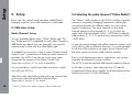
WCU - 3
Instruction Manual
As of: February 2012
ALL ARTWORK, PICTURES AND TEXTS ARE COVERED BY OUR COPYRIGHT.
THEY MUST NOT BE COPIED FOR REPRODUCTION (E.G. ON CD-ROM DISKS OR INTERNET-SITES) OR USED IN THEIR ENTIRE FORM OR IN EXCERPTS WITHOUT OUR PREVIOUS WRITTEN AGREEMENT.
IF YOU ARE DOWNLOADING PDF-FILES FROM OUR INTERNET HOME-PAGE FOR YOUR PERSONAL USE, MAKE SURE TO CHECK FOR UPDATED VERSIONS.
WE CANNOT TAKE ANY LIABILITY WHATSOEVER FOR DOWNLOADED FILES, AS TECHNICAL DATA ARE SUBJECT TO CHANGE WITHOUT NOTICE.
This page is left intentionally blank
2
1. Contents .......................................................... 3
6. Battery Maintenance ................................... 26
2. Safety Instructions and Legal Disclaimer ......... 4
7. Specifications .............................................. 27
2.1 Safety instructions ............................................... 4
2.2 Disclaimer ........................................................... 6
Contents
1. Contents
8. ARRI Service .................................................29
3. General Description ...................................... 8
3.1 ARRI Order Numbers ..........................................
3.2 Control Scope ...................................................
3.3 Common Operating Procedures .............................
3.4 Status Screen Elements .........................................
10
11
12
13
4. Operation .......................................................... 14
4.1 Screen Menus ................................................... 14
5. Setup ................................................................ 18
5.1 Wireless Setup .................................................. 18
5.2 Selecting the radio channel (“Yellow Radio“) ................. 18
5.3 Selecting the radio channel (“White Radio“) ................. 19
5.4 Optional Zoom Control ........................................ 20
5.5 Wired Setup ..................................................... 22
5.6 Knob Friction Adjustment ...................................... 25
3
Safety instructions
2. Safety Instructions and Legal Disclaimer
2.1.
Safety instructions
General safety instructions
The WCU-3 has been thoroughly tested
for quality of workmanship and operating
functions before leaving the factory.
Read and understand all safety and operating
instructions before you operate or install the
system.
To ensure optimal performance, it is essential
that you aquaint yourself with this instruction
manual and that you follow the operating
instructions described.
Retain all safety and operating instructions for
future reference.
Warning signs
Heed all warnings on the system and in the
safety and operating instructions before you
operate or install the system.Follow all installation and operating instructions.
Possible risk of injury or damage to equipment.
Do not use accessories or attachments not
recommended by ARRI, as they may cause
hazards and void the warranty.
This symbol indicates the risk of electric shock
or fire danger that could result in injury or
equipment damage.
Do not repair any part of the system. Repairs
must only be carried out by authorized ARRI repair
shops.
Do not remove any safety measure of the system.
4
Do not place the system on an unstable cart,
stand, tripod, bracket, or table. The system
may fall, causing serious personal injury and
damage to the system or other objects.
Operate the system using only the type of
battery and charger indicated in the manual.
Do not use solvents to clean.
Any violation of these safety instructions or the nonobservance of personal care could cause serious injuries
(including death) and damages on the system or other
objects.
Note:
Notes are used to indicate further informations
or informations from other instruction manuals.
Product Identification
When ordering parts or accessories, or if any questions
should arise, please advise your type of product and
serial number.
Safety instructions
Do not operate the system in high humidity
areas or expose it to water or moisture.
5
Disclaimer
2.2
Disclaimer
Before using the products described in this manual be sure to read and
understand all respective instructions. The ARRI Wireless Lens Control
System is only available for commercial customers. The customer grants
by utilization, that the ARRI Wireless Control Unit (WCU-3) or other
components of the system are only deployed for commercial use. Otherwise
the customer has the obligation to contact ARRI preceding the utilization.
While ARRI endeavors to enhance the quality, reliability and safety of their
products, customers agree and acknowledge that the possibility of defects
thereof cannot be eliminated entirely. To minimize risks of damage to
property or injury (including death) to persons arising from defects in the
products, customers must incorporate sufficient safety measures in their
work with the system and have to heed the statuted canonic use.
No part of this document may be copied or reproduced in any form or by
any means without prior written consent of ARRI. ARRI assumes no
responsibility for any errors that may appear in this document. The
information is subject to change without notice.
6
patents, copyrights or other intellectual property rights of third parties by
or arising from the use of ARRI products or any other liability arising
from the use of such products. No license, express, implied or otherwise,
is granted under any patents, copyrights or other intellectual property
rights of ARRI or others.
ARRI or its subsidiaries expressly excludes any liability, warranty,
demand or other obligation for any claim, representation, or cause, or
action, or whatsoever, express or implied, whether in contract or tort,
including negligence, or incorporated in terms and conditions, whether by
statue, law or otherwise. In no event shall ARRI or its subsidiaries be
liable for or you have a remedy for recovery of any special, direct,
indirect, incidental, or consequential damages, including but not limited
to lost profits, lost savings, lost revenues or economic loss of any kind or
for any claim by third party, downtime, good-will, damage to or
replacement of equipment or property, any costs or recovering of any
material or goods associated with the assembly or use of our products,
or any other damages or injury of persons and so on or under any other
legal theory.
For actual design-in, refer to the latest publications of ARRI data sheets or
data books, etc., for the most up-to-date specifications. Not all products and/
or types are available in every country. Please check with an ARRI sales
representative for availability and additional information.
In the case one or all of the forgoing clauses are not allowed by
applicable law, the fullest extent permissible clauses by applicable law
are validated.
ARRI or its subsidiaries does not assume any liability for infringement of
ARRI is a registered trademark of Arnold & Richter Cine Technik GmbH & Co Betriebs KG.
Disclaimer
This page is left intentionally blank
7
General Description
3. General Description
The Wireless Control Unit WCU-3 combines robust
2-axis lens control with radio control capability in
combination with any member of the 3rd generation
(“Yellow Radio“) or 4th generation (“White Radio“)
ARRI Wireless Remote System.
Bidirectional data transmission allows the display
of actual camera status and ARRI LDS lens data, if
available.
Main features
•
•
•
•
•
•
•
•
•
•
•
•
•
8
Light-weight handheld unit
Integrated Iris and Focus controls
Clearly arranged controls and menus
Easy readable display under all lighting conditions
Illuminated controls
Weatherproof design
Left-handed operation at “the press of a button“
Powered from integrated, removable battery or
external power supply
Fully integrated in the ARRI Wireless Remote System
Optional hard-wired operation via ARRI LCS-bus
Optional 3-axis lens control with ARRI ZMU-3 Zoom
Control on bracket
Mixed wired and wireless control
ALEXA Plus/Studio Lens Control compatible
ZMU-3 Bracket fixing
Multifunction display
Iris control slider
Mechanical knob
end stops
K2.65132.0 ZMU-3 Bracket assy.
Adjustable handle
Focus control knob
Illuminated knob index
Direct controlpushbuttons
K2.65162.0
Camera RUN/stop
WCU-3 ON/off
Lens motors CALibration
Set/reset KNoB angle limits
Set/reset knob lens LIMits
Set/reset slider lens LIMits
General Description
Antenna (non-detachable)
LCS connectors
marker disk Z-type
K2.47851.0
Li-Ion Battery
Standard
marker disk
Belt clip
Jog wheel for
function control
Battery compartment
Battery release button
K2.47852.0
Battery Charger
9
General Description
3.1 ARRI Order Numbers
K2.65155.0
Wireless Control Unit WCU-3 complete,
built-in „Yellow“ Radio
consists of
K5.67999.0
K2.47248.0
05.21150.0
K2.65155.W
WCU-3 Wireless Control Unit
WCU-3 User Manual
Marker disk - standard
Belt
Wireless Control Unit WCU-3 complete,
built-in „White“ Radio
Cables:
consists of
K5.67999.0
K2.47248.0
05.21150.0
WCU-3 Wireless Control Unit
WCU-3 User Manual
Marker disk - standard
Belt
Recommended battery and charger
K2.47851.0
K2.47852.0
K2.65236.0
10
Charger power cords:
05.20369.0
Power Cord UK
05.20370.0
Power Cord US
05.20368.0
Power Cord EU
SONY NP-FM 500H
Li-Ion Battery 7,2V 11.8Wh
SONY BC-VM50 Li-Ion Battery Charger
with Power Cord EU
Battery and charger set
2x Battery, 1x Charger w.Europe + US plug
K4.41395.0
K4.41397.0
K2.65159.0
K2.65009.0
K2.65010.0
K2.41389.0
K-LC-Z1-S LCS cable 3,5m (11ft)
K-LC-M1-Sp-S LCS spiral cable
KC 129-S WCU-3 to ZMU-3 cable 0,25m (0.8ft)
KC 92-S LCS to ZMU-3 cable 0,8m (2.5ft)
KC 93-S LCS to ZMU-3 cable 10m (33ft)
LC-E1 LCS Cable Drum Extension 75m (250ft)
Accessories:
K2.65132.0
K2.65162.0
K2.65176.0
ZMU-3 Bracket assy. for WCU-3
Marker disk - Z- type
Wooden Handgrip Assy.
Wireless
Hardwired
Compatible partner units Radio Type vs. min. SW Version
„Yellow“
„White“
Using the ARRI LCS-Bus wiring, the WCU-3 accepts the
Cameras/Lens Motor Control Units (UMC-X) mentioned in the
„Wireless Section“ as well as the units listed below for control
and/or communication.
WCU-3
ALEXA Plus/Studio
ARRIFLEX 435 Adv w. FEM-2
ARRIFLEX 435 Xtreme
ARRIFLEX 416 Plus (HS)
ARRICAM w. LDB-ST/LT
D21 with FEM-2
UMC-3(A)
UMC-1 w. URM-2/-3
Packet
SUP
Packet
Packet
Packet
Packet
Packet
Packet
Firmware
02A
3.1
03D
03D
03B
04D
1.17
02F
1.60
02A
3.1
04A
04A
04A
05A
*
04A
---
* D21 (SW-Packet 1.17) with FEM-2 Packet 3.00
The ZMU-3(A) extends the WCU-3‘s control capabilities to an
additional zoom control, being powered from the WCU-3‘s
battery.
Note:
Radio communication is only possible between equally color
coded radio units:
“Yellow Radio“ to Yellow Radio“,
“White Radio“ to “White Radio“
Mixed wireless and wired control
Wireless control of axis not LCS-wired is also possible
WCU-3 acessory units
ZMU-3 (A)
ZMU-1/-2
CLM-1
UMC-1
Firmware
Firmware
Firmware
Firmware
General Description
3.2 Control scope
02C
2.09
2.18
1.60
To tap the full potential of the WCU-3‘s possibilities, be sure to
having updated all connected units to a software version equal
or higher to those listed.
For setup details please refer to chapter 5.
11
General Description
3.3 Common Operating Procedures
The pushbuttons on the front allow access to the main functions.
ON
RUN
CAL
CLM-3 Lens Motor Operation:
Due to its very high torque, the CLM-3 motor needs
special attention in usage.
Careless calibration or mounting may ruin lens mechanics!
To minimize the risk of lens damages, any ARRI CLM-3
capable lens control system with a CLM-3 connected,
sends a CAL request every time a CLM-3 drive unit has
been repowered. ONLY in case you are REALLY SURE
that the CLM-3 motor setup has not been changed, you
may override this CLM-3 dependent CAL request by
double-pressing the CAL button within 0.5 seconds.
KNB
12
Press briefly to switch-on the WCU-3. To switch-off
the WCU-3 press and hold ON for more than 2 seconds.
Starts/stops the connected camera (toggle function)
CAL request on the display: Press CAL button
briefly for lens motor calibration
Intentional Calibration: Press and hold CAL for more
than 2 seconds to run a calibration cycle
Turn the focus knob to the desired START focus value.
Press and hold the KNB button and turn the focus knob to
the chosen STOP focus value*. Release the KNB button.
LIM
LIM
Turn the focus knob to the desired START focus value.
Press and hold the LIM button and turn the focus knob
to the chosen STOP focus value*. Release the LIM button.
Shift the iris slider to the desired START iris value.
Press and hold the LIM button and shift the iris slider to
the chosen STOP iris value*. Release the LIM button.
*During change-over to the STOP position the appropriate
or
symbol appears in the display, toggling in
size. After successfully setting the limits, the larger
symbol appears steadily in the display.
Reset from limitation by briefly pressing the appropriate button.
Note:
This description assumes that the iris is assigned to the slider and
the focus is assigned to the knob.
The jog wheel, located on the lower end of the pushbutton line, allows access to the WCU-3‘s menu system.
Press the jog wheel button to enter the menu system from
the initial (status) screen or to select the highlighted menu
item.
Turn the jog wheel to make a - highlighted - choice from
the displayed menu items.
To exit from any menu, highlight the EXIT
symbol in
the lower right screen corner and press the jogwheel button.
Color
WHITE
GREEN
RED
Film Camera
STANDBY
RUN
ASY
Camera Status
STANDBY: Preset camera speed
RUN: Actual camera speed
Actual camera shutter angle
Exposed film length / remaining recording time
Unit depends on magazine setting
Camera power supply voltage
Operational information
Message line
Lens Motor Status
Lens Data
information, if available
Unit depends on LDS lens
or Lens Data Archive settings
Video Camera: Exposure Index and White Balance setting
Knob
Lens Motor Limits information
Slider
EXIT symbol
RF signal strength
Radio channel
WCU-3 Status
General Description
3.4 Status Screen Elements
Battery charge status
Different WCU-3 Status symbols will be
shown in hardwired configuration, for a
detailed description refer to chapter 5.5
ALEXA Screen example
Free Storage Space
Exposure Index
Camera Status
red : Record
green : Standby
Basic White Balance
setting information,
CC not shown
Note:
The displayed data depends on the connected camera or
motor control unit:
e.g. an ARRIFLEX 416 cannot transmit its shutter angle in standby,
an UMC-1/URM-2 cannot send camera data, etc.
13
Operation
4. Operation
Backlight Menu
Slide in the battery into its compartment. Switch on the
WCU-3 using the blue ON button.
The display illumination can be adjusted to 3 brightness
levels or may be switched off completely.
Select the desired brightness level, press, then highlight the
EXIT
symbol and press to return to the Status Screen.
The Status Screen appears and the WCU-3 tries to
connect to a matching partner unit. If ok, CALibrate the
lens motor(s) and the WCU-3 is ready for operation.
Some user-definable functions can be adjusted through a
simple menu system.
4.1 Screen Menus (WCU-3 SW packet 02A)
Enter the WCU-3 Main Menu by briefly pressing the
jog wheel button.
The Main Menu Screen appears.
Channel Menu
Select the radio channel or switch off the radio by turning
the jog wheel. Press to return to the Status Screen.
EXIT symbol
14
Highlight one of the provided menu items by turning the
jog wheel, push briefly the jog wheel button to enter the
next menu level or select the EXIT
symbol and press to
return to the Status Screen.
“Yellow Radio“ screen
“White Radio“ screen
For a detailed description of the ARRI wireless system setup refer to
chapter 5.ff
The Options Screen holds special user dependent
functions as well as the Software Version information.
EXIT symbol
Button Usage programs the LIM buttons to either setting
Limits or adding Lens Scale Offset used in UMC-3(A) 3D
applications or correction of Lens Data Archive scales.
Knob controls either the Focus or Iris lens motor.
The respective other axis will be directed to the Slider.
Knob and Slider may be set to clockwise or counter-clockwise direction operation.
Note: To allow the use of seperate WCU-3‘s for Focus
and Iris control, control should be set up like this:
Highlight the chosen item and confirm your selection by
briefly pressing the jog wheel button.
Highlight the
, i or
symbol and press to select the
sub-screens or return to the Status Screen.
The Display Alignment allows the display view to be turned
upside down for easier use for left-handed people.
For even more convenient handling of the WCU-3 also turn
the side handle by 180°. Use a 3mm hex wrench for the
handle adjustment.
Operation
Options Menu
Note: Due to the upside down orientated antenna, the
transmission range may be reduced.
screen
WCU-3 Software and Hardware Version information
i screen
WCU-3 #1: Knob controls Focus -> controls Focus Lens Motor
WCU-3 #2: Knob controls Iris -> controls Iris Lens Motor
15
Operation
Motor Torque Limit Menu
Torque Adjustment Instructions
In this screen the CLM-3 motor torque can be adjusted in
four steps. The adjustment is only available if a motor
with high power drive is detected (UMC-3A, ARRIFLEX
416 PLUS (HS) or ALEXA Plus/Studio)
high value (4) - high torque - low value(1) - low torque
Please select the required torque level carefully:
Higher torque levels should be used for rough-running lenses.
Note: Take care to re-calibrate the CLM-3 motor after re-attachment
of the motor and after each lens change!
Ignoring this procedure can lead to severe lens damage.
Lower torque levels should be used for smooth-running lenses.
Note: If the torque level is not adequate to lens properties or
operation temperature, the electronic torque limitation may
cause a high-frequency noise.
Use a higher torque level to reduce this effect.
Note: Controlling the ALEXA Plus/Studio, torque adjustment is
possible at the ALEXA Plus/Studio only.
16
Message Descriptions
Currently no function, reserved for future applications.
Searching for host
Connection lost
Go to second limit
No motor control
Battery empty
Please calibrate
WCU-3 searches for wireless partner
unit
wireless partner unit switched-off,
distance too high or interference with
other wireless units
limitation settings: Turn knob or shift
slider to the second limit position
no lens motor connected,
another WCU-3 already drives
the selected lens motor
shut-off the WCU-3 and replace/recharge the battery immediately
lens motors need calibration
Operation
Lens Menu
17
Setup
5. Setup
5.2 Selecting the radio channel (“Yellow Radio“)
Every time, the control setup has been established or
changed, a power cycle and calibration is advisable.
The “Yellow“ radio modem in the WCU-3 utilises a specific
scheme of constantly changing frequencies, making the
connection between the different radio units very robust
against interference. The even channels on the radio
channel selector switch (numbers 0, 2, 4, 6) utilize the
upper half of the bandwidth (2444 - 2472 MHz) while the
odd numbers (1, 3, 5, 7) use the lower frequencies (2406
- 2435 MHz).
5.1 Wireless setup
Radio Channel Setup
The two available Radio types “White“ Radio and “Yellow“ Radio are NOT compatible to each other! Therefore
ARRI Radio equipped units can generally only control/
communicate to units with the same Radio type.
To establish a connection of one or more Wireless Hand
Control Units* (a maximum of three per radio channel is
possible), the WCU-3 must be set to the same radio
channel as the camera or the Motor Control Unit.
Please refer to Section 3.2 for unit‘s compatibility.
It is not possible to control more than one motor control
unit with one WCU-3.
Select the radio channel by pushing the jog wheel at the
unit‘s lower side and select the Channel Menu.
Please refer to Section 4.1 for details.
18
*
WCU-3, WMU-3, the WMU-2 supports „Yellow“ Radio only
In case two remote systems with yellow antenna washer must
work side by side on different channels, it is recommended
to set one of the systems to an upper (even) channel and
the other system to a lower (odd) channel number.
Due to local telecommunications regulations, only certain
channels are allowed in some countries.
The WCU-3 must be used with odd channel numbers in France.
In all other countries, radio channels from 0-7 may be
programmed if there are no specific local telecommunication
restrictions for the 2.4 GHz ISM-band.
The new “White“ radio has, aside from being available,
the advantage of offering more robust transmission
through direct sequence spread-spectrum and adjacent
channel rejection technologies. Thus the “White“ radio is
less prone to interference from other wireless devices
and can better co-exist with WLAN devices on the set.
The “White“ radio modem in the WCU-3 utilises a different
transmission scheme compared to the “Yellow“ radio,
therefore it is connecting to other “White“ radio equipment
only.
To establish a connection of one or more Wireless Hand
Control Units* (a maximum of three per radio channel is
possible), the WCU-3 must be set to the same radio
channel as the camera or the Motor Control Unit.
Please refer to Section 3.2 for unit‘s compatibility.
It is not possible to control more than one motor control
unit with one WCU-3.
Frequency range is the ISM 2.4 GHz. Modulation
scheme used is DSSS (Direct Sequence Spread Spectrum).
ARRI Ch. Nr.
Frequency
0
1
2
3
4
5
6
7
2,410 GHz
2,415 GHz
2,430 GHz
2,435 GHz
2,450 GHz
2,455 GHz
2,470 GHz
2,475 GHz
Setup
5.3 Selecting the radio channel (“White Radio“)
In case two remote systems with white antenna washer
must work side by side on different channels, it is
recommended to set one of the systems to even channel
and the other system to a neighbor - odd - channel
number.
Select the radio channel by pushing the jog-wheel at the
unit‘s lower side and select the Channel Menu. Refer to
Section 4.1 for details.
*
WCU-3, WMU-3
19
Setup
Channel selection on motor control units:
Control troubleshooting
Use the rotary channel selection knob on the LDB-2 (Lens
Data Box), the FEM-2, the UMC-3(A) or ARRIFLEX 416
plus(HS).
Selector switch number 9 switches the radio modem off,
number 8 is reserved for special purposes.
Press the LCS button on the ALEXA Plus/Studio, and select
the same channel as on the WCU-3.
For a detailed description of the radio channel setting on
units other than the WCU-3 please refer to the respective
operation manual.
- Axis lost: configuration has been changed while the
units have been powered-on -> re-power and calibrate
- Focus or Iris not available in a separate control system:
set both Focus and Iris to Knob control on their respective control units and re-power the units
- Jerky motor drive: mixed-up LCS connections for old
(-1/2) and new (-3) hand units or motors (see page 22)
Radio connection troubleshooting
-
incorrect modem type (“Yellow“ - “White“ mixed-up)
wrong channel setting - channel mismatch
broken antenna or dirty antenna socket on partner units
too long or too short distance to foreign party radio
units, depends on local conditions
- interfering (illegal) foreign party transmitters
- another WCU-3 already drives the selected lens motor
20
5.4 Optional Zoom Control
Connecting the ZMU-3(A) via cable KC 129-S and the
WCU-3 to ZMU-3 bracket (refer to page 10 for order
numbers), the WCU-3 may be expanded to a three axis
lens control system. The ZMU-3(A) will be powered from
the WCU-3 battery in wireless mode.
Only a ZMU-3(A) may be supplied from the WCU-3
battery in wireless operation. Any other connected unit
must have its own power supply.
ALEXA Plus/Studio
D21+FEM-2 + URM-3
ARRIFLEX 435 Adv. + FEM-2 + URM-3
ARRIFLEX 435 Xtreme
ARRIFLEX 416 Plus
ARRICAM LT/ST + LDB-2*
3-axis motor control with separate units
2x WCU-3 + ZMU-3(A)+WZE
Knob controls
lens motors
CLM-2 or CLM-3
Focus
Setup
Sample configurations - Radio controlled operation
WCU-3 OPTIONS Screen
Knob controls
Iris
WCU-3 OPTIONS Screen
Focus
Iris
Zoom
ZMU-3(A) + WZE
Zoom
3-axis compact motor control
1x WCU-3 + ZMU-3(A)
UMC-3(A)
Combinations of wireless and wired
control configurations are also possible
* ARRICAM + LDB (any type) do not support CLM-3 lens motors
21
Setup
5.5 Wired setup
The WCU-3 also allows hard-wired operation via the
ARRI LCS-bus. The WCU-3 may be connected to any
supported camera, motor controller or lens motor
through any standard LCS cable.
The “cable“
symbol in the display‘s status line
appears, when an external power supply is detected,
and “Hardwire“ replaces the radio information.
The radio module shuts-off automatically, regardless of
its channel setting.
Note:
22
The WCU-3‘s battery will NOT be charged through
any external power supply!
The WCU-3 provides two independently controlled
LCS sockets. Do not use -1/-2 and -3 accessory units
within the same LCS chain!
3-axis compact motor control
ALEXA Plus/Studio
D21+FEM-2 (+ URM-3)
ARRIFLEX 435 Adv. + FEM-2 (+ URM-3)
ARRIFLEX 435 Xtreme
ARRIFLEX 416 Plus
ARRICAM LT/ST + LDB-2*
1x WCU-3+ZMU-3(A)
Setup
Sample configurations - wired operation
Lens motors
CLM-2 or CLM-3
LCS
3-axis motor control with separate units
2x WCU-3 + ZMU-3(A)
Focus
LCS
Iris
Zoom
ZMU-3(A)
Zoom
Knob controls
Iris
Combinations of wireless and wired
control configurations are also possible
Knob controls
Focus
K4.41395.0 LC-Z1-S LCS cable 3,5m (11ft)
K4.41397.0 LC-M1-Sp-S LCS spiral cable
K2.41389.0 LC-E1 LCS Cable Drum Extension 75m (250ft), use with LC-Z1-S
K2.65159.0 KC 129-S WCU-3 to ZMU-3 cable for use with WCU-3 bracket
K2.65009.0 KC 92-S LCS to ZMU-3 cable 0.8m (2.5ft)
K2.65010.0 KC 93-S LCS to ZMU-3 cable 10m (30ft)
UMC-3(A)
* ARRICAM + LDB (any type) do not support CLM-3 lens motors
23
Setup
LCS-Supported Units
Cameras:
ARRIFLEX 416 PLUS (HS)
ARRIFLEX 435 Advanced + FEM-2
ARRIFLEX 435 Xtreme
ARRICAM + LDB-ST/-LT
D21 + FEM-2
ALEXA Plus/Studio
Accessories:
UMC-1
UMC-3(A)
ZMU-1/-2/-3(A)
CLM-1
24
Setup
5.6 Knob Friction Adjustment
A unique feature of the WCU-3 is its very smooth knob
action. Additionally, the friction is user adjustable.
Remove the knob‘s rubber ring. Open the three crossheaded countersunk screws that are accessible now.
Pull-off the knob cover.
Now you have access to the friction adjustment. Release
the knurled head screw and rotate the whole assembly
clockwise for stronger friction or counterclockwise for easier action. Fasten the knurled head screw again, when
the desired setting is found.
knurled head screw for
friction adjustment
NEVER open any other screw of this assembly.
The knob encoder may become misaligned or
damaged, resulting in the unit having to be returned to the factory for a costly re-adjustment
or encoder replacement.
NEVER open this screw!
25
Battery Maintenance
6. Battery Maintenance
The following batteries are recommended for use with
the WCU-3:
SONY NP-FM Series (e.g. NP-FM 500H)
Recommended Charger:
SONY BC-VM50
For safety purposes, only use the recommended charger
and battery types.
Please also take note of the following directives for
battery handling:
Do not incinerate
Do not expose to temperatures beyond
-20 to +50°C ( -4 to +122°F)
Do not disassemble
26
Replace or re-charge the battery, if the “Low Battery“
message on the WCU-3 Status Screen appears.
The charger must only be used indoors. Do
not expose it to humidy or high temperatures.
Note:
For achieving full battery capacity, leave the
battery for about one hour in the charger after
the charge LED has gone out.
From time to time discharge and re-charge the battery
completely to maintain full long-term capacity.
Defective batteries must not be thrown into
domestic waste, but disposed of onshore in a
safe manner consistent with all applicable
regulations.
Operating temperature
-20 to +50 °C ( -4 to +122°F )
Operating voltage
7.2V Li-Ion battery
Specifications
7. Specifications
Typ. current consumption
165mA @ 7,2V with radio, backlight “off“
175mA @ 7,2V with radio, backlight “high“
Dimensions ( h * w * d ) with antenna
147*132*109mm (5.8*5.2*4.3in)
Weight
800g (25.7oz) without battery
730g (28.2oz) with battery
27
Specifications
Declaration of Conformity
Declaration of Conformity
We, Manufacturer
ARRI CINE + VIDEO GERÄTE GmbH
Pottendorferstraße 25-27/3/2/1
A-1120 Wien
declare that the product
Wireless Control Unit
We, Manufacturer
ARRI CINE + VIDEO GERÄTE GmbH
Pottendorferstrasse 25-27
A-1120 Wien
declare that the product
Wireless Zoom Extension Unit
WCU-3
WCU-3
is in conformity with
WHITE marked
is in conformity with
DIN EN 55103-1: 1997-06
DIN EN 55103-2: 1997-06
DIN EN61000-3-2: 2006-10
DIN EN61000-3-3: 2006-06
DIN EN 60065: 2003-01
DIN EN 55103-1: 1997-06
DIN EN 55103-2: 1997-06
DIN EN61000-3-2: 2006-10
DIN EN61000-3-3: 2006-06
DIN EN 60065: 2003-01
Modular Certification of built in RF-modem ARRI EMIP100
EN 300 328 V1.7.1: 2006-10
additional Certifcation of built in RF-modem AC4424I-100
EN 301 489-1 V1.8.1: 2008-04
EN 301 489-17 V2.1.1: 2009-05
EN 300 328-1 V1.3.1: 2001-12
EN 300 328-2 V1.2.1: 2001-12
FCC CFR 47 Part 15: 10-2009
Listed under FCC ID: Y7N-EMIP100
EN 301 489-1 V1.3.1: 2001-09
EN 301 489-17 V1.1.1: 2000-09
FCC Rule Parts 15 C
Date:
2008-07-07
RSS-Gen Issue 2: June 2007
RSS-210: Issue 7: June 2007
Listed under IC: 9482A-EMIP100
Signature
Ing. Walter Trauninger
28
Date:
2011-05-02
Signature
Ing. Walter Trauninger
WorldWide Service Network
Active Hotlines:
Passive Hotlines:
Munich, Germany
Arnold & Richter Cine Technik
+49 89 3809 2121
[email protected]
Hong Kong
ARRI Asia Limited
+852 2537 4266
[email protected]
London, Great Britain
ARRI CT Limited
+44 1895 457 051
[email protected]
Sydney, Australia
ARRI Australia Pty Ltd
+61 2 9855 4305
[email protected]
Rome, Italy
ARRI Italia S.r.l.
+39 335 749 00 70
[email protected]
Burbank, USA
ARRI Inc. West Coast
+1 877 565 2774
[email protected]
ARRI Service
8. ARRI Service
New York, USA
ARRI Inc. East Coast
+1 877 565 2774
[email protected]
Toronto, Canada
ARRI Canada Limited
+1 416 255 3335
[email protected]
29
technical data is subject to change without notice
© ARRI 2012
WCU-3 User Manual
ARRI Order no. K5.67999.0
ARNOLD & RICHTER CINE TECHNIK Türkenstr. 89 D-80799 München
Phone +49 (0)89 - 3809-0 Fax +49 (0)89 - 3809-1244
www.arri.com