1
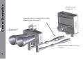
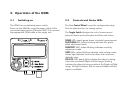
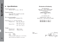
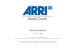
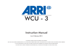
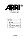
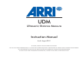
UDM
Ultrasonic Distance Measure
Instruction Manual
As of: August 2011
ALL ARTWORK, PICTURES AND TEXTS ARE COVERED BY OUR COPYRIGHT.
THEY MUST NOT BE COPIED FOR REPRODUCTION (E.G. ON CD-ROM DISKS OR INTERNET-SITES) OR USED IN THEIR ENTIRE FORM OR IN EXCERPTS WITHOUT OUR PREVIOUS WRITTEN AGREEMENT.
IF YOU ARE DOWNLOADING PDF-FILES FROM OUR INTERNET HOME-PAGE FOR YOUR PERSONAL USE, MAKE SURE TO CHECK FOR UPDATED VERSIONS.
WE CANNOT TAKE ANY LIABILITY WHATSOEVER FOR DOWNLOADED FILES, AS TECHNICAL DATA IS SUBJECT TO CHANGE WITHOUT NOTICE.
Contents
1. Contents
1. Contents ............................................................ 2
2. Safety Instructions and Legal Disclaimer .... 4
2.1 Safety instructions ................................................... 4
2.2 Disclaimer ................................................................ 5
3. General Description ........................................ 7
3.1 ARRI Order numbers ................................................. 9
4. Setup ......................................................................... 10
5. Operation of the UDM ................................ 11
5.1 Switching on ........................................................ 11
5.2 Controls and Status LEDs .......................................... 11
5.3 Operation Settings ............................................... 12
5.4 Parameter Settings ................................................... 12
5.5 Depth-of Field and Focus Tracking ........................... 13
6. Specifications ................................................ 14
7. ARRI Service ................................................... 15
2
This page is left intentionally blank
3
Safety instructions
2. Safety Instructions and Legal Disclaimer
2.1.
Safety instructions
The UDM has been thoroughly tested for quality of
workmanship and operating functions before leaving
the factory.
To ensure optimal performance, it is essential that you
aquaint yourself with this instruction manual and that
you follow the operating instructions described.
Warning signs
Do not use accessories or attachments not
recommended by ARRI, as they may cause
hazards and void the warranty.
Do not repair any part of the system. Repairs must
only be carried out by authorized ARRI repair shops.
Do not remove any safety measure of the system.
Do not operate the system in high humidity
areas or expose it to water or moisture.
Possible risk of injury or damage to equipment.
This symbol indicates the risk of electric shock
or fire danger that could result in injury or
equipment damage.
General safety instructions
Read and understand all safety and
operating instructions before you operate or
install the system.
4
Retain all safety and operating instructions
for future reference.
Operate the system using only the type of
power source indicated in the manual.
Do not use solvents to clean.
Any violation of these safety instructions or the non-observance of
personal care could cause serious injuries (including death) and
damages on the system or other objects.
Product Identification
When ordering parts or accessories, or if any questions should
arise, please advise your type of product and serial number.
Disclaimer
Before using the products described in this manual be sure
to read and understand all respective instructions. The ARRI
Wireless Lens Control System is only available for commercial
customers. The customer grants by utilization, that the ARRI
Ultrasonic Distance Measure (UDM) or other components of
the system are only deployed for commercial use. Otherwise
the customer has the obligation to contact ARRI preceding the
utilization.
While ARRI endeavors to enhance the quality, reliability and
safety of their products, customers agree and acknowledge
that the possibility of defects thereof cannot be eliminated
entirely. To minimize risks of damage to property or injury
(including death) to persons arising from defects in the
products, customers must incorporate sufficient safety
measures in their work with the system and have to heed the
statuted canonic use.
No part of this document may be copied or reproduced in any
form or by any means without prior written consent of ARRI.
ARRI assumes no responsibility for any errors that may appear
in this document. The information is subject to change without
notice.
For actual design-in, refer to the latest publications of ARRI
data sheets or data books, etc., for the most up-to-date
specifications. Not all products and/or types are available in
every country. Please check with an ARRI sales representative
for availability and additional information.
ARRI or its subsidiaries does not assume any liability for
infringement of patents, copyrights or other intellectual property
rights of third parties by or arising from the use of ARRI products
or any other liability arising from the use of such products. No
license, express, implied or otherwise, is granted under any
patents, copyrights or other intellectual property rights of ARRI or
others.
ARRI or its subsidiaries expressly excludes any liability, warranty,
demand or other obligation for any claim, representation, or
cause, or action, or whatsoever, express or implied, whether in
contract or tort, including negligence, or incorporated in terms
and conditions, whether by statue, law or otherwise. In no
event shall ARRI or its subsidiaries be liable for or you have a
remedy for recovery of any special, direct, indirect, incidental, or
consequential damages, including but not limited to lost profits,
lost savings, lost revenues or economic loss of any kind or for
any claim by third party, downtime, good-will, damage to or
replacement of equipment or property, any costs or recovering
of any material or goods associated with the assembly or use of
our products, or any other damages or injury of persons and so
on or under any other legal theory.
In the case one or all of the forgoing clauses are not allowed by
applicable law, the fullest extent permissible clauses by applicable law are validated.
ARRI is a registered trademark of Arnold & Richter Cine Technik GmbH & Co Betriebs KG.
Disclaimer
2.2
5
This page is left intentionally blank
6
The ARRI Ultrasonic Distance Measure (UDM) provides
a continuous reflection-based distance measurement
and automatic focus tracking, using the built-in Lens
Data System of the ALEXA Plus, ARRICAM, ARRIFLEX
435 Advanced/Xtreme and ARRIFLEX 416plus cameras
or the UMC-3 lens motor controller.
Main features
•
•
•
•
•
•
Measurement range from approx.
0,4 - 10m / 1ft 4in - 33ft
Selectable Meter / Feet display
Automatic focus tracking with ARRI Lens
Data System equipment
Pre-set measuring limits for exact object
tracking
Fine-trimming for best performance
in different environments
Large transflective LCD display for good
readability under all light conditions
The UDM consist of two units, the Display Unit and the
Sensor Unit. 3/8“ UNC bushings allow the units to be
mounted on standard supports in convenient positions.
The UDM comes with an 1,5m (5ft) interface cable.
Connection cables for interfacing to cameras and
UMC-3 must be ordered seperately (page 9).
A large control wheel on the Display Unit allows easy
setting of the UDM parameters, supported by a set of
status LEDs.
The small toggle switch under the large LCD display
changes the unit of measurement between meters and feet.
General Description
3. General Description
7
General Description
Display Unit
K2.65131.0
optional power supply/data cable
please refer to page 9
Sensor Unit
K2.65130.0
UDM-Sensor Cable (blue label)
K4.65655.0
8
ARRI Order Numbers
K0.60055.0 Ultrasonic Distance Measure UDM
complete
The package includes:
K2.65144.0 Cable UDM-UMC-3 ((1,5m/5ft))
connects UDM Sensor Unit to UMC-3/AUX
K2.65130.0 UDM Sensor Unit
K2.65131.0 UDM Display Unit
K2.65261.0 Cable UDM-ALEXA ((1,5m/5ft))
connects UDM Sensor Unit to ALEXA/EXT
K4.65655.0 Cable UDM-Sensor (1,5m/5ft)
connects Sensor Unit to Display Unit
K2.65240.0 Cable UDM-RS ((1,5m/5ft))
connects UDM Sensor Unit to ARRI-RS connector
K5.65999.0 UDM User Manual EN
K2.65262.0 Cable UDM-PSC ((0,7m/2.5ft))
connects UDM Sensor Unit to PSC cables
General Description
3.1
PSC Cables
Optional Accessory:
K4.65656.0 Cable UDM-CAM (1,5m/5ft)
connects UDM Sensor Unit to ARRICAM - CAC
K4.65672.0 Cable UDM-435 (1,5m/5ft)
connects UDM Sensor Unit to
ARRIFLEX 435 Advanced/Xtreme or
ARRIFLEX 416 PLUS
ARRI order no. Description Length
K2.65206.0 PSC-XLR3 1,5m/5ft
K2.65207.0 PSC-XLR4 1,5m/5ft
K2.65208.0 PSC-DTAP 0,6m/2ft
K2.65209.0 PSC-HI12 0,6m/2ft
K2.65210.0 PSC-FI11 0,6m/2ft
K2.65211.0 PSC-RS
0,6m/2ft
K2.65212.0 PSC-FI2 1,5m/5ft
K2.65213.0 PSC-LCS 0,6m/2ft
connects to
24volts battery
12volts battery
Anton Bauer D-Tap socket
Hirose 12pin socket
ARRIFLEX 435, SONY FF35
ARRI RS socket
ARRI OBB-2 battery
ARRI LCS bus
Function
Power supply only
Power supply only
Power supply only
Power supply only
Power supply only
Power supply only
Power supply only
Power supply only
9
Setup
10
4. Setup
4.1. Standard Setup - Distance measurement only
Fasten the UDM units in convenient places on or around the
camera using the 3/8” support on both units. Connect the
Display to the Sensor Unit using the blue labeled cable.
Choose the applicable supply cable either for ALEXA ,
ARRICAM, ARRIFLEX 435 / 435Advanced / 435Xtreme / 416 / 235
camera or the optionally available UMC-3 cable. You may
create custom supply cables at your own risk.
Refer to chapter 6 for detailed information.
4.2. LCS Setup - Depth-of-Field Display and Focus Tracking
Using suitable cameras and accessories, the UDM provides
the operator with actual Depth-of-Field information on the
LDD-FP and controls automatic focus tracking when
required.
The UDM sends the distance information repeatedly in a
serial data stream to the connected unit. Applicable units
are ARRI cameras providing a LDD connector and built-in
lens motor drives, like the ALEXA Plus, the ARRICAM-ST/LT
equipped with a Lens Data Box and an unit incorporating
a LDD-FP connector, an ARRIFLEX 435 Advanced/Xtreme
with FEM-2 or an ARRIFLEX 416 plus.
Alternatively a UMC-3 will also interface the UDM data to
an LDD-FP in non-ARRI set-ups (e.g. video camera usage). As
the LDD-FP provides the complete UDM information, the Display
Unit may be disconnected after parameters have been set.
Applicable Cameras and Accessories
Cameras
- ARRICAM Studio, Studio Lens Data Box, Studio Readout
- ARRICAM Lite, Lite Lens Data Box, Lite Frame Glow or
Remote Control Station with cable KC 65 or KC 69
- ARRIFLEX 435Advanced/Xtreme, FEM-2
- ARRIFLEX 416plus
- UMC-3, LDD-FP with Lens Table stored in Lens Data Archive
- ALEXA and ALEXA Plus
Cable Control
- LCS-bus cable LC-Z1/LC-Z2/LC-M1/LC-M2
- WHA-3 + WFU-1/3
- CLM-2
Metering
- LDD-FP with Cable LDD-RDO K2.54172.0
Wireless Control
- WMU-3, WFU-3, WEB-3, WBU-3/-4, LDD-FP
Always use the latest Camera- and UMC-3 software packets
for secure operation.
5.1
Switching on
The UDM has no dedicated power-switch.
Power-on the UDM by using the power switch of the
connected supply source (Camera/UMC-3) or connect
the appropriate UDM cable to the supply unit.
5.2
Controls and Status LEDs
The blue Control Wheel is used for configuration setup.
Push to select and turn to change values.
Operation
5. Operation of the UDM
The Toggle Switch changes the unit of measurement
between Metres and centimetres and Feet and inches.
SENSE LED: steady green shows successful measurement
FILM PLANE LED: yellow blinking indicates film plane
offset adjustment mode
SENSTIVITY LED: yellow blinking indicates sensitivity
adjustment mode
LIMIT LEDs: yellow blinking indicates value setting mode,
steady light indicates limits set to other than maximum
(default) value.
LDS-DOF LED: steady light indicates the object as being
within the calculated Depth-of-Field range, blinking
indicates the object to being outside of the Depth-of-Field
range. No light indicates, that no camera Depth-of-Field
signal is available.
11
Operation
5.3
Operation Settings
During operation the following changes or adjustments
are available:
Selection of the unit of distance measurement
Use the toggle switch to select either m/cm or ft/in
Setting of sensitivity
Press the control wheel briefly - the SENSITIVITY LED starts
blinking, indicating the device is in sensitivity mode. Turn
the control wheel and set the new sensitivity value. The
value range starts at 0 (OFF) and ends at 100 (MAX).
Adjust so that you achieve a steady green SENSE light in
the desired measurement range. Press the control wheel
briefly again to return to normal operation.
Setting of Film Plane offset
When the Sensor Unit is not mounted on the film plane,
the Film Plane offset will need to be recalibrated.
Measure the distance between the film plane and the
object. Press and hold the Control Wheel for about
1.5sec, until the FILM-PLANE LED starts blinking.
Turn the Control Wheel until the correct distance is
displayed. Press the Control Wheel briefly again to return
to normal operation.
12
5.4
Parameter Settings
Enter the parameter setting mode by pressing and holding
the Control Wheel during power-on. Scroll through the
parameter settings by repeatedly pressing the control
knob briefly. The following settings are available:
Display backlight brightness
Default value: L 100
settings from 0 to 200
LOWER LIMIT display range (Lower LIMIT LED blinking)
Default value: 0.00 m / 0 ft 0 in
settings from 0 to 15.00 m / 49ft 2in
UPPER LIMIT display range (Upper LIMIT LED blinking)
Default value: 15.00 m / 49ft 2in
settings from 15.00 m / 49ft 2in to 0
Display Resolution - step width of least significant digit
Default value: r 0
settings from 0 to 5
Default Reset
Default value d no
dEF
stores user set parameters
resets to default values
Press and hold the Control Wheel to return to normal operation.
Operation
5.5
Depth-of-Field and Focus Tracking
Using the settings and accessories described in chapter
4.2, the UDM uses the LDD-FP or the WRC-2 with LDD-FP
software option as a display for the actual Depth-of-Field.
As the LDD-FP provides the complete UDM information,
the UDM Display Unit may be disconnected after
parameters have been set.
Indicators on the LDD-FP show the following:
An active UDM (or CTM), the measured distance and
actual Depth-of-Field. Depth-of-Field is shown graphically
as a bar graph and is also displayed as numeric value.
In a cabled configuration the Focus Tracking function can
be activated by pressing and holding the blue tracking
button on the left side of the WHA-3.
Using the wireless setup, press and hold the BRIGHT - UP
button on the LDD-FP.
As long the button is kept pressed, the focus motor will
follow the measured distance.
Typical LDD-FP image, indicating
- UDM (CTM) active
- measured distance
green dart and numeric value
- Depth-of-Field
bar-graph and numeric value
13
Specifications
6. Specifications
Declaration of Conformity
We, Manufacturer
ARRI CINE + VIDEO GERÄTE GmbH
Pottendorferstrasse 25-27/3/2/1
A-1120 Wien
declare that the product
Ultrasonic Distance Measure
UDM
Operating temperature
-20 to +50 °C (-4 to +122 °F)
Operating voltage
10 to 30 V DC (12/24V nominal)
ARRICAM compatible
Typ. current consumption
0,024A (24V) / 0,040A (12V)
is in conformity with
DIN EN 61326-1: 2006-10
DIN EN 55011: 2003-08 (Group1/ClassB)
DIN EN61000-4-2: 2001-12
DIN EN61000-4-3: 2003-11
DIN EN61000-4-4: 2002-07
Dimensions (h * w * d) with connector
Display Unit:
83 * 75 * 32 mm
3.3 * 2.9 * 1.3 in
Sensor Unit:
73 * 74 * 91 mm
2.9 * 2.9 * 3.6 in
Weights
Display Unit:
Sensor Unit:
140 g (5 oz)
120 g (4.2 oz)
Power connections
pin1
GND
pin4
+Vbat
14
suitable connector: ARRI order no. 05.21182.0
LEMO FHJ.0B.304.CYMD52Z or equivalent
Date:
2007-05-27
Signature
Ing. Walter Trauninger
Germany
Arnold & Richter Cine Technik
Türkenstraße 89
D-80799 München, Deutschland
phone:
+49 (0)89 3809-0
fax:
+49 (0)89 3809-1245
fax service: +49 (0)89 3809-1793
e-mail service: [email protected]
ARRI Camera Rental
Türkenstraße 89
D-80799 München, Deutschland
phone:
+49 (0)89 3809-1240
fax:
+49 (0)89 3809-1798
e-mail: [email protected]
USA
GB
ARRI GB Limited
2 Highbridge
Oxford Road
Uxbridge
Middlesex, UB8 1LX, England
phone: +44 (0)1895 457 000
fax:
+44 (0)1895 457 001
e-mail: [email protected]
Italy
ARRI Italia S.R.L.
Viale Edison 318
20099 Sesto San Giovanni (Milano), Italia
phone: +39 02 262 271 75
fax:
+39 02 242 1692
e-mail: [email protected]
ARRI Inc.
(East Coast)
617 Route 303
Blauvelt, NY 10913-1123
phone: +1 845 353 1400, USA
fax:
+1 845 425 1250
e-mail: [email protected]
ARRI Inc.
(West Coast)
600 North Victory Blvd.
Burbank, CA 91502-1639, USA
phone: +1 818 841 7070
fax:
+1 818 848 4028
e-mail: [email protected]
ARRI Service
7. ARRI Service
ARRI Italia S.R.L.
Via Placanica 95
00040 Morena (Roma), Italia
phone: +39 06 79 89 02 1
fax:
+39 06 79 89 02 206
e-mail: [email protected]
Canada
ARRI Canada Limited
415 Horner Avenue, Unit 11
Toronto, Ontario M8W 4W3
Canada
phone: +1 416 255 3335
fax:
+1 416 255 3399
e-mail: [email protected]
15
technical data is subject to change without notice
© ARRI 2011
UDM User Manual
ARRI Order no. K5.65999.0
ARNOLD & RICHTER CINE TECHNIK Türkenstr. 89 D-80799 München
Phone +49 (0)89 - 3809-0 Fax +49 (0)89 - 3809-1244
www.arri.com