1
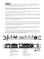
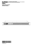
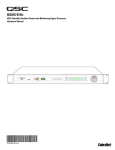
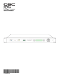
BASIS 722az
8x8 Control and Monitoring Signal Processor
Hardware Manual
*TD-000145-00*
TD-000145-00 rev.A
IMPORTANT SAFETY PRECAUTIONS & EXPLANATION OF SYMBOLS
The lightning flash with arrowhead symbol within an equilateral triangle is intended to alert the user to
the presence of uninsulated “dangerous” voltage within the product’s enclosure that may be of sufficient
magnitude to constitute a risk of electric shock to humans.
The exclamation point within an equilateral triangle is intended to alert the user to the presence of
important operating and maintenance (servicing) instructions in this manual.
SAFEGAURDS
Electrical energy can perform many useful functions. This unit has been engineered and manufactured to
assure your personal safety. Improper use can result in potential electrical shock or fire hazards. In order
not to defeat the safeguards, observe the following instructions for its installation, use and servicing.
CAUTION: To reduce the risk of electric shock, do not remove the cover. No user-serviceable parts inside.
Refer servicing to qualified service personnel.
WARNING: To prevent fire or electric shock, do not expose this equipment to rain or moisture.
1- Maximum operating ambient temperature is 50°C (122°F).
2- Never restrict airflow through the device fan or vents. Please insure that the air intake and exhaust
vents are unobstructed.
3- When installing equipment into rack, distribute the units evenly. Otherwise, hazardous conditions
could be created by an uneven weight distribution.
4- Connect the unit only to a properly rated supply circuit. The BASIS 722az is suitable for connection to
100 - 240 VAC, 47 - 440 hertz, with no special considerations other than the appropriate IEC power cord.
5- Reliable Earthing (Grounding) of rack-mounted equipment should be maintained.
LITHIUM BATTERY WARNING
THIS EQUIPMENT CONTAINS A NON-RECHARGEABLE LITHIUM BATTERY. LITHIUM IS A CHEMICAL
KNOWN TO THE STATE OF CALIFORNIA TO CAUSE CANCER OR BIRTH DEFECTS. THE NON-RECHARGEABLE LITHIUM BATTERY CONTAINED IN THIS EQUIPMENT MAY EXPLODE IF IT IS EXPOSED TO FIRE OR
EXTREME HEAT. DO NOT SHORT CIRCUIT THE BATTERY. DO NOT ATTEMPT TO RECHARGE THE NONRECHARGEABLE LITHIUM BATTERY.
FCC INTERFERENCE STATEMENT
NOTE: This equipment has been tested and found to comply with the limits for a class B digital device,
pursuant to part 15 of the FCC rules. These limits are designed to provide reasonable protection against
harmful interference in a residential installation. This equipment generates, uses, and can radiate radio
frequency energy and if not installed and used in accordance to the instructions, may cause harmful
interference to radio communications. However, there is no guarantee that interference will not occur in
a particular installation. If this equipment does cause harmful interference to radio or television reception, which can be determined by switching the equipment off and on, the user is encouraged to try to
correct the interference by one or more of the following measures:
- Reorient or relocate the receiving antenna.
- Increase the separation between the equipment and the receiver.
- Connect the equipment into an outlet on a circuit different from that to which the receiver is connected.
- Consult the dealer or an experienced radio or TV technician for help.
© Copyright 2004 QSC Audio Products, Inc. QSC® is a registered trademark of QSC Audio Products, Inc. “QSC” and the QSC logo are registered
with the U.S. Patent and Trademark Office. All trademarks are the property of their respective owners.
2
Introduction
The BASIS 722az provides the signal processing, control and status monitoring facilities needed to bind a group of amplifiers and loudspeakers into an integrated functioning system. In conjunction with QSControl.net software, the BASIS 722az enables the user to
design, test and deploy professional audio reinforcement and distribution systems.
Each QSC power amplifier connects directly to a BASIS 722az via one of its four QSC DataPorts. All mission-critical elements of the
BASIS-driven sound system are monitored. User-selected events are logged and loudspeaker protection features unique to BASIS such
as QSC's power limiter are made possible through the DataPort functionality.
A standard Windows computer is the principle user-interface for controlling the overall BASIS/QSControl system. However, the BASIS
722az also offers a front panel interface for accessing a few critical functions.
A single QSControl server computer can support several clients running QSC's latest Venue Manager software. Thus, the sound system
can be operated via several computers, roaming wireless laptops, tablets, etc., all at the same time, from anywhere a connection to the
QSControl network is available.
The QSControl network can also be managed from a single computer running both the client and the server. Once all devices in a system
are configured, a computer is no longer required on that system’s network. All basic functions of the BASIS 722az continue to operate
with or without a control computer connected to the network.
Audio enters a BASIS 722az through analog line inputs, is processed per your custom DSP configuration, and output via the DataPorts.
Unlike other configurable DSP boxes, the intrinsic processing latency of the BASIS 722az is both short and fixed at 0.396 milliseconds.
When analog input and analog outputs are used, the total delay is 2.354 milliseconds. The delay does not change regardless of the DSP
configuration, unless the configuration intentionally adds more delay.
Both software and firmware can be easily updated over the network. In the future, QSC will be adding new capabilities to both BASIS
and QSControl.net. Our latest code releases and access to up-to-date information on BASIS and QSControl.net are available at
www.qscontrol.net. We invite you to visit us there.
We've applied our many years experience in supporting high-end installed sound with our previous system-building products such as
RAVE, QSControl, CM16a, DSP-3, DSP-4, and DSP-30. The BASIS 722az brings all that technology together in one compact, powerful,
easy to use system. We are confident that your new BASIS 722az will provide years of dependable service and we hope it will help you,
the system designer and implementer, to express your creative audio system ideas.
1- Power indicator
2- Diagnostic indicator
3- Network status indicators
4- Port connection status indicators
5- Multi-function push buttons
6- Display
7- Rotary select/accept knob
8- Reset push switch (recessed)
9- DataPorts
10- Analog inputs
11- Monitor chain in/out
12- Relay outputs
13- Logic outputs
14- Omni inputs
15- RS-232 port
16- Network status indicators
17- QSControl 10BaseT receptacle
18- IEC power inlet
See page 9
for detailed
descriptions.
3
Block Diagram
Introduction - Networking the BASIS 722az
The BASIS 722az includes an RJ-45 network connection port on the rear panel, which is labeled "QSControl". All data communications
between the BASIS 722az and a control computer, such as a PC running the QSControl.net server or client application, takes place via this
rear panel QSControl port. The QSControl port supports connection to a 10BASE-T Ethernet network via industry-standard unshielded
twisted pair cabling (UTP) rated at category 5 or better.
Notes on Network Systems Design:
As with any communications system, the reliability and performance of a local area network is intimately related to the designer's skill and
knowledge in implementing a topology that is robust, efficient and standards-compliant. Proper network design is even more critical in distributed multimedia systems. Therefore, it is important for the system designer to realize that some conventional network practices may not
be well suited for network implementations that include a BASIS 722az. Although each network design is unique and may carry its own performance requirements, compliance to the following two points will assist in building an audio management network that is trouble free and
efficient.
First, data communications between the BASIS 722az and any computing devices (QSControl.net server or client applications) should not
share the same LAN or VLAN with other forms of traffic. This is especially applicable with audio and video content. QSC always recommends that all QSControl and QSControl.net data content remain isolated from all other network communications. Doing so will ensure a
network with predictable behavior and one that offers the highest level of confidence and long-term reliability.
Second, the BASIS 722az and QSControl.net system are targeted at network switch deployments. The consumer costs of Ethernet switches
have continued to fall over the last several years and are now comparable with repeaters on a per-port basis. In addition, the sophistication
and scalability of network switches make them ideal for new installations. However, we do realize that designers may wish to add BASIS
products to existing QSControl installations that are built on repeater LAN topologies. This applies primarily to existing 10BASE-T networks
designed for QSC’s CM16a products. For this very reason we continue to support connectivity to network repeater hardware with the BASIS
722az. However, the system designer must realize that repeater technology has bandwidth and network management limitations that may
reduce the performance of the BASIS 722az or reduce the number of devices that can coexist reliably on the same network.
To learn more about network design rules and system compliance visit the QSC network resources page at http://www.qscaudio.com/products/network/resources.htm.
Audio management over Ethernet may seem daunting if you are new to networking. However, it all boils down to connecting a few simple
cables between various networking devices. Most of the time it "just works". QSC was the first in our industry to offer amplifier control and
monitoring over standards-compliant Ethernet. Our CM16 and CM16a products paved the way for audio management via Ethernet and they
continue to operate trouble free in systems all over the world.
The following example will help get you started, but they just scratch the surface of what can be achieved with advanced networking…
4
Example 1- QSControl.net X-over mode:
This example illustrates the simplest connection you can make between the BASIS 722az and a computer. You simply use a CAT-5
crossover cable connected between the BASIS 722az rear panel QSControl port and a computer's network interface card, (NIC). Note
that the computer’s NIC must support 10BASE-T Ethernet (nearly all do). No network switch or repeater is required with this simple connection scheme. With QSControl.net server and client software running on your computer, you can completely set up and monitor your
BASIS 722az.
QSControl Port
BASIS 722az
CAT-5 Crossover Cable
QSControl.net
NIC
Example 2- Unmanaged Switch:
This example illustrates an unmanaged Ethernet network. An unmanaged switch is used to provide a dedicated QSControl network for
the BASIS 722az and all other QSControl devices, including a management PC running the QSControl.net server or client application.
As many BASIS devices may be connected to the network as there are switch ports available. All BASIS units will be able to communicate with the computer. Larger networks can be created by interconnecting multiple switches, so long as appropriate design rules are
administered.
QSControl Port
BASIS 722az
CAT-5 Cable
Unmanaged Switch
CAT-5 Cable
QSControl.net
NIC
5
Example 3- Managed Switch (configured with multiple VLANS):
This example illustrates a managed Ethernet network. An managed switch is used to partition the network into two domains; one for
QSControl traffic and one for all non-QSControl traffic. The partitioning provides a dedicated virtual local area network (VLAN) for the
BASIS 722az and all other QSControl devices, including a management PC running the QSControl.net server or client application. As
with example #2, as many BASIS devices may be connected to the network as there are switch ports available. All BASIS units will be
able to communicate with the computer. Larger networks can be created by interconnecting multiple switches, so long as appropriate
design rules are administered.
QSControl Port
BASIS 722az
CAT-5 Cable
VLAN #2
VLAN #1
Managed Switch
CAT-5 Cable
CAT-5 Cable
non-QSControl Data
QSControl.net
NIC
6
Unpacking
There are no special unpacking precautions. However, it is recommended you keep the original packing material for reuse in the rare
event that service be required. If service is required and the original packing material is not available, ensure that the unit is adequately
protected for shipment (strong box of appropriate size, sufficient packing material to prevent load-shifting or impact damage) or call
QSC’s Technical Services Department for packing material and a carton.
What is included in the carton:
Item
Description
1
BASIS 722az
2
Self-adhesive rubber feet
3
Hardware Manual (this document)
4
QSControl.net Software CD
5
IEC Power Cord 3 x #18 AWG
6
3-pin terminal block connector
7
2-pin terminal block connector
8
5-pin terminal block connector
Quantity
1
4
1
1
1
10
10
1
Mounting
The BASIS 722az can be used in or out of an equipment rack. Rack mounting is optional. Adhesive rubber feet are included for non-rack
mount installations. Use them to prevent the unit from scratching or marring support surfaces.
Rack Mounting
Rack mount the BASIS 722az by supporting it from underneath while aligning the mounting holes with the threaded screw holes in the
rails; install all four mounting screws and washers and tighten securely. Ensure use of all four mounting screws in order to minimize the
chance of bending or distorting the rack mount ears. If the BASIS 722az is to be transported while in a rack, we recommend supporting
the rear of the chassis. This will help prevent the unit from being damaged from the increased mechanical stresses of portable and
mobile use. The BASIS 722az’s chassis includes integral rear mounting tabs for securing to the rack mounting ears.
Be certain not to block the cooling air ventilation openings on the sides of the chassis.
Be certain not to block the cooling
air ventilation openings on the
sides of the chassis.
7
Computer Requirements & Software Installation
Installing QSControl.net is easy. All you need to do is choose the folder where the program is to be stored (the default setting is acceptable
for most applications). We recommend your system meet the following minimum requirements:
1- IBM PC compatible computer with a Pentium 4 processor.
2- Processor speed of 1 GHz (2 GHz or faster recommended for systems with 30 or more BASIS units).
3- 512 megabytes of RAM (1 gigabyte recommended for systems with 30 or more BASIS units).
4- Hard drive with at least 500 MB of free space for the program and files you generate.
5- Display resolution of 1024 X 768, 16-bit color.
6- CD-ROM drive to install the software.
7- 10BaseT or 10BaseT/100BaseTx network interface card
8- Windows XP Professional, XP Home, Windows 2000 SP2 (or better), or Windows NT4.0 SP6a operating system. Windows 95, 98 and ME
platforms are not supported.
Note: If system is used for real-time adjustments and configuration of audio systems, we recommend all Windows Power Options (located in
the Windows Control Panel) features be disabled. Display, hard drive, system standby and hibernation settings should be set to “Never”.
This avoids waiting for the system to “wake-up” if adjustment is needed after an elapsed period of time.
To Install QSControl.net:
1- Start your computer and start Windows.
2- If there are any programs running, please close them now. Be sure to leave Windows running.
3- Place the QSControl.net CD-ROM in your CD-ROM drive. If your system supports the Auto Run feature installation begins automatically,
otherwise, you can click Start on the task bar, click Run, and browse for the file named setup.exe from the CD.
4- Click the Install QSControl.net button.
5- Follow the installation instructions on the screen.
To Uninstall QSControl.net:
1- Click the Start menu button and choose Settings/Control Panel.
2- Double-click the Add/Remove Program icon.
3- Select QSControl.net from the list, then click Add/Remove.
4- Click Yes to confirm you would like to uninstall QSControl.net.
General Information & Configuration Memories
Amplifier Setup
The QSC DataPort-equipped amplifiers connected to the BASIS 722az must have their power switches in the “on” position. For initial testing,
use the lowest useful gain setting until the system is operating as expected. After the system setup has been verified and tested, gain settings may be adjusted as required.
Network
The network should be operable and QSControl.net software should be installed/running on the system controller computer.
Configuration Memories
The BASIS 722az has non-volatile storage locations that contain settings for the device as well as DSP signal flow. The storage locations
make it possible to set up the BASIS for different situations and quickly recall the setup with or without QSControl.net software using the
front panel controls.
8
Connections
AC Power Cord
Insert the molded receptacle of the AC power cord into the AC
power inlet on the back of the BASIS 722az. Plug the AC line
connector into the AC outlet. The power supply will accept from
100 to 240 Volts AC, 47 to 440 Hertz, without any changes. If a
different type of IEC power cord is required than supplied with
your 722az, contact QSC’s Technical Services Department.
QSControl connection.
Accepts ruggedized or
normal shell-less RJ45
plugs.
QSControl
Connect one end of a category-5 cable terminated with an RJ45
plug into the QSControl receptacle. Insert the RJ45 plug into
the receptacle with the lock-tab oriented toward the bottom of
the BASIS 722az and push firmly until the connector locks into
place (usually an audible “click” can be heard). Connect the
other end to the appropriate QSControl.net network port.
Analog Audio Inputs
Eight balanced audio inputs are provided, CH 1 INPUT - CH 8
INPUT. Plug the input signal terminal block connectors into the
input receptacles. Connection pin-out is printed on the rear
label for reference. Refer to the illustrations for balanced and
unbalanced connections. Use balanced audio inputs whenever
possible.
Omni In
The six Omni In connectors are two-pin terminal block connectors. They can accept contact closure devices (switch, relay
contacts), 10k ohm variable resistors, TTL logic level, and 0-5
VDC input.
The contact closure and logic devices accommodate on/off or
state-change events; the variable resistor input provides full 8bit resolution allowing for incremental-change events. Refer to
the illustrations for connection recommendations. NOTE! +48
volts is the absolute maximum that can be applied to the + pin
without damage. Voltage is with respect to chassis or the - pin.
Analog audio inputbalanced connection.
Analog audio inputunbalanced connection. Note jumper
wire between - and
ground.
Omni In connections.
Variable input must be
10k ohm variable
resistor. Contact closure input can be a
switch or relay contacts. These inputs
can operate software
“devices”. Negative () terminal is at chassis
potential.
Logic Out
The four Logic Out connectors are two-pin terminal block connectors. They provide CMOS logic level compatible signals for
external devices.
Relay Out
Two sets of relay contacts are provided, RELAY OUT 1 and
RELAY OUT 2. Contacts are floating and rated for 30VDC, 1A.
There is one common terminal, one normally-closed contact terminal and one normally-open contact terminal. These are
labeled as C, NC and NO on the rear panel. When the relay is
not energized, the C terminal is connected to the NC terminal
and the NO terminal is not connected; when the relay is energized the C to NC connection is opened and the C to NO connection is closed.
Logic Out connections.
Negative (-) terminal is
at chassis potential.
Positive (+) terminal
logic level is switched
using software.
Relay Out connections.
Refer to text, at left, for
explanation.
9
Monitor Chain
The MONITOR CHAIN connector is a 5-pin terminal block connector. Input and output connections are balanced. The center pin is the shield connection for both the input and output
of the monitor chain. Connection is shown at right. The left-most + and - terminals are for
monitor chain input signals, while the right-most terminals are for monitor chain output signals. When powered down, a relay connects the input to the output, thus bypassing the
BASIS 722az in the monitor chain.
Monitor Chain connection.
See explanation, at left.
In
RS-232
The RS-232 is a utility serial port for accessing certain diagnostic and setup features. Connect to an available COM port on your PC and communicate using a terminal control program such as Windows Hyperterminal.
Use a normal serial data cable with a DB-9 male plug to connect to the BASIS 722az. To connect the cable, orient the connector properly, then push into the receptacle until it is firmly
seated; tighten the retaining screws “finger tight”. Communications should be 9600 baud,
no parity, 8 data bits, 1 stop bit, and flow control Xon/Xoff.
Ports
PORT A through PORT D are QSC DataPorts. When using the BASIS 722az with QSC
DataPort-equipped amplifiers or QSC DSP products (DSP-3, DSP-4) connect to the BASIS
722az using QSC DataPort cables. The 722az supports up to eight channels of DataPort
audio and amplifier status monitoring. This can be four 2-channel amplifiers or one 8-channel amplifier or other suitable combinations.
If connecting a multi-DataPort amplifier, ensure all the DataPorts of the amplifier are connected and that they are all connected to the same BASIS.
To connect the cable, orient the connector properly, then push into the receptacle until it is
firmly seated; tighten the retaining screws “finger tight”.
LED Indicators
When the BASIS 722az is plugged into a properly functioning AC outlet, it will power up and
briefly display a welcome screen on the LCD display.
POWER Indicator- This blue indicator illuminates when the BASIS 722az is plugged into a
properly functioning AC source. There is no power switch on the BASIS 722az. This helps to
prevent accidental system shutdowns.
DIAGNOSTIC Indicator- This red indicator illuminates during the power-on self test, then
should extinguish. If it remains illuminated, this indicates that the self-test has detected an
unexpected event, such as corrupted firmware or a memory boot failure. If the DIAGNOSTIC
LED remains illuminated, try resetting the BASIS 722az by cycling power off and on once.
Should the indication persist, contact QSC’s Technical Services for guidance. During operation, any system fault will fully illuminate the indicator. During a “flash” update, the indicator will blink on and off; this is normal. Any error detected will be displayed on the LCD. For
purpose of unit identification, the LED can be remotely turned on using QSControl.net software.
(continued, next page)
10
Out
LED Indicators (continued)
QSControl and CobraNet Network Status (Port) Indicators- There is a group of three LEDs on the front and rear panels
of the BASIS 722az labeled RX, TX and LINK. These indicate the connection status of the BASIS 722az to the QSControl network. Their functions are described below. Note: the Port indicators on rear panel for the CobraNet Port do not have LEDs
installed because the BASIS 722az is not a CobraNet enabled device.
RX (receive)- This indicator illuminates any time the BASIS 722az receives data from the corresponding network.
TX (transmit)- This indicator illuminates whenever the BASIS 722az transmits data onto the corresponding network.
LINK STATUS- The corresponding indicator illuminates when the BASIS 722az is connected to an operating network.
PORTS indicators- These indicators are labeled A through D. These indicators are either off, red, green, or yellow, depending on what is connected to the port. The indications are:
off- nothing attached
red- QSC DSP accessory attached
green- QSC DataPort amplifier attached
yellow- QSC DSP and Amplifier combination attached
LCD Display and Controls
The BASIS 722az has a 2 line X 16 character LCD display. The display and the multi-function push-button switches on either
side provide data access and editing capability. The push-button switches on either side of the display are used to navigate
through the menus. The rotary select/accept knob is active for many displayed items allowing you to scroll through choices by
rotating the control, and accepting choices (entering) by pushing in on the control.
The accessible menus and sub menus may appear differently than example shown. Software updates may occasionally
improve the interface. The basic navigation flow for the BASIS 722az menu system is shown on the following page.
Front Panel Password Lockout
The password lockout provides the ability to restrict access to all of the editable parameters available on the LCD front panel.
This feature is enabled or disabled via QSControl software only (refer to the “General Tab” area and click on the “Front Panel
Password” button). when the lockout feature is enabled, all front panel LCD functions are readable, but editing of parameters
is now password protected. While in this mode, any attempt to edit a parameter will require the user to enter the Front Panel
Password. The default factory password is “qsc”. The password is stored in the BASIS unit and can be changed using the
QSControl software.
Once the password has been correctly entered, the BASIS will allow edits to the parameters.
After 5 minutes of inactivity, the BASIS will automatically reset the Front Panel Password lockout. Re-entry of the password
will be required to resume editing.
The lockout mode can be deliberately disabled via the “Disable Edits” checkbox in the Front Panel Password menu of the
QSControl software.
11
LCD Navigation Map (typical)
Left side buttons have screen
dependent functions.
Use rotary data wheel to edit data. Rotate to
move cursor and push to accept change.
Boot Screen
This read-only screen is the
“out of the box” default display after power up. This is
the most desired information
when first setting up a network system. Once user
moves to a different screen,
the last screen accessed
becomes the new power up
default.
Main Menu Screens:
Right side buttons serve
as up/down navigation.
Arrow characters indicate right side button
context. If additional
menus are available, the
arrow character will be
shown.
Utility Menu Screens:
Password Log-in Menu*:
Custom User Menus:
*Note: After successful password entry, all screens with editable parameters will have read
write capability. Without password entry, these screens will
be read-only.
If no faults exist
12
Getting Started
This section outlines one of the simpler methods of getting familiar with your BASIS and the QSControl.net software. The goal of this
procedure is to get your computer and the BASIS connected and communicating and the QSControl.net software installed and running.
After the software is installed and running, refer to the software’s Help file for all software related operation/issues. Note! The default
password for the BASIS is “qsc” (no quotes, lower case).
1- Turn off the computer and unplug the power cord from the BASIS 722az.
2- Connect a CAT-5 crossover cable from the computer’s network interface card (NIC) to the BASIS QSControl jack (example 1, page 6).
3- Reconnect the power cord to the BASIS 722az (turn it on). Using the BASIS LCD display and controls, navigate the menu to the IP
Address and make a note of it. In steps 12 and on, you will need to change the IP address of the BASIS or your PC.
4- Turn on the PC and start Windows. You must have Administrator rights and be signed on as Administrator in order to install the
QSControl program. Ensure you are signed on to the computer as the Administrator.
5- Place the QSControl.net CD-ROM in your CD-ROM drive. The install wizard should start. If not, you can also select Start then Run
and browse for the file named setup.exe from the CD.
6- The installer queries the computer for available drive space and other information. If required MDAC library (Microsoft) files are not
already on the computer, the library files are installed. You must accept the Microsoft software agreement in order to install the MDAC
library. It may be necessary to reboot the computer after library installation.
7- At the prompt for “Client/Server” selection, keep both Client and Server selected. This will be appropriate for general use.
8- When prompted “Select Installation Folder”, specify the installation directory or accept the default location.
9- You will be prompted to select an installation accessible by everyone (non-secure) or an installation accessible only to you (secure).
Select the appropriate Everyone or Just Me box and continue. Installation proceeds.
10- Reboot only if your computer prompts you to do so.
11- Right click on the My Network Places icon on your computer’s desktop. Select Properties. Select Local Area Connection, and
view its properties (click Properties tab). Highlight the Internet Protocol Properties tab and view its properties. You will see an
entry field for the IP address. Decide whether you want to change the IP address of your computer to be similar that of to the BASIS
(easiest if you have many BASIS units) or if you want to change the IP address of your BASIS to be similar to that of the computer. This
is a network management decision.
12- Change the IP address of the BASIS (or computer) to be compatible with that of the computer (or BASIS). Typically, this is done by
making the IP address of one of the devices 1 digit different in the last octet (group of digits in IP address). If changing the computer’s
settings, write down the current values, in case you want to revert later.
13- The subnet mask address should be exactly the same for both the computer and the BASIS. The Gateway address should not be
altered as it is not used.
14- After you are satisfied with all your settings, close all open windows and start the QSControl.net program. Select Start, Run,
QSControl.net, QSControl.net.exe.
15- The login screen should open. The default password is “qsc” (lower case, no quotation marks). Select “Logon to Local Computer”
and click OK.
16-The QSControl.net Venue Manager window will open.
13
Getting Started (continued)
17- Select Device, Add New Device, from the menu. A new window will open prompting you to name the device. Name it logically,
such as BASIS 1, or similar. Select the Device Type and select BASIS 722az. At the Password prompt, enter “qsc” (lower case, no quotation marks). This is the device password, separate from the software password. The default, in both cases, is “qsc”, but you are free
to change either or both. Enter the IP address of the BASIS and click OK.
18- The BASIS will now appear in the inventory root (left side of screen). If the BASIS does not show in the inventory root, check that a
crossover cable is used (only for BASIS connected directly to PC), check the cable connections, verify IP addresses are set correctly, verify Subnet masks are set correctly, and verify AC power is properly applied to the BASIS.
19- Click on the BASIS 722az in the inventory root. A view of applicable device tabs will open. Click the DSP tab and the current DSP
configuration of the BASIS will be displayed.
20- Right click on the Design Editor icon in the lower left of your display; select “New”. A new window opens; select BASIS 722az for
the device type.
21- Click on Help to access the software’s Help system. All software operation is covered in the on-line help file.
Operation of the BASIS 722az is accomplished with the included QSControl.net software. No software operation is covered in this hardware manual. After installing your software, open the Help file
and follow its recommendations. The software Help file includes the most recent information available for your BASIS 722az.
14
Operation
QSControl Port
The QSControl port operates on a 10BaseT Ethernet network. This port is one of the primary means for connecting QSControl.net to the
BASIS. The port may connect directly to a PC's 10BaseT or 10/100 (auto-sensing or auto-negotiating) network interface card using a
crossover cable. Data from the QSControl port may also pass through network repeaters, network switches and routers. We strongly
recommend the use of network switches to facilitate higher bandwidth and dedicated connections.
Utility/Diagnostic Functions
Safe Mode Switch
Location of Safe Mode switch: The front panel has a small access hole on the left side, just left of the Power indicator. It is not
labeled to help prevent accidental use. The Safe Mode switch can be operated by using a paper-clip (or similar item) inserted into the
access hole and pushing.
Safe Mode: Use if the BASIS 722az becomes inoperable (or behaves in completely unexpected ways) after updating firmware.
If the BASIS 722az operates in an unexpected way or is not responding to any communications after a new firmware file is uploaded to
it, it is likely the file was corrupted during transfer. If this occurs, there is a “backup” program in the BASIS 722az that will enable you
to communicate with it.
How to put the BASIS 722az into Safe Mode:
1- Turn off the power to the BASIS 722az by unplugging it from the AC outlet.
2- Depress the safe mode switch and keep it depressed while plugging the unit back in (power on).
3- The BASIS 722az is now in “safe mode”. You may release the switch.
You should now be able to re-establish limited TCP/IP communications with the BASIS 722az. Once communication has been re-established, the file transfer can be tried again or the old application file used until the source of the data transfer problem can be found.
Also, QSControl.net WILL NOT communicate with the BASIS 722az if it is in “safe mode”. You may communicate only using TFTP, Telnet,
or RS-232.
RS-232 Serial Port I/O Interface
The RS-232 connector on the rear panel is used as a serial port input/output (I/O). This I/O port is used for accessing Ethernet/IP settings, stand alone control capabilities, system “health” data, firmware version information and other related data.
Should any system problems arise, the data that may be accessed through this interface can help to track down the problem. The most
common items that might be used are “Display Network Settings” and “Enter Network Setup”. Many of the remaining selections would
typically be used for troubleshooting purposes along with a QSC technical representative prompting you to access particular menu
items so the data can be interpreted.
Connection is made using a normal serial cable between your computer’s serial port and the RS-232 port of the BASIS 722az. Once
properly connected, a “dumb-terminal” program (such as Hyper Terminal, a widely used version on most Windows-based PC’s) is
started and communication established between the PC and the BASIS 722az.
Following is the basic procedure for starting up Hyper Terminal, naming the connection, specifying the communications settings and an
example of “what you should see” for a text-menu once the communications link has been established. If programs other than Hyper
Terminal are used, you will need to follow your software’s instructions for establishing communications through your PC’s COM (serial)
port.
15
Utility/Diagnostic Functions (continued)
RS-232 Communications Procedure:
1) Connect the RS-232 port of the BASIS 722az to an unused serial port (COM port) of a PC using a normal (straight through) serial
cable.
2) Open the HyperTerminal program. This program is usually started by clicking the Windows Start icon, selecting Programs, then
Accessories, Communications, and finally, highlighting the Hyper Terminal folder and clicking on its icon.
3) After starting Hyper Terminal, a Connection Description window will pop-up. It will require that you name your connection.
Enter a name for your new connection (example: BASIS 722az) and click OK to continue.
4) Next, Hyper Terminal needs to know how to “talk” to the BASIS 722az. This selection depends on which port on your PC the cable
is connected to. Ignore the first three entry fields (phone number information) and go directly to the Connect using entry field and click
on the down arrow for the drop-down menu selection. Select the port the BASIS 722az is connected to and click OK to continue. The
Properties window should appear next.
5) The Properties window for the selected COM port should now be active. For the Port Settings, use the following information so
communication between the BASIS 722az and the computer is in the same “language”.
Bits per Second: 9600
Data Bits: 8
Parity: none
Stop Bits: 1
Flow Control: Xon/Xoff
Once you have set the properties as outlined, click OK to continue. If all the connections and communications settings are correct, the
main Hyper Terminal window will open.
6) The Hyper Terminal main window will appear next, but blank. Type the letter “h” (for help) and then press the “Enter” key. This will
prompt the BASIS 722az to post its menu text. The “h” key is the Help prompt for the BASIS 722az. A text menu will appear. This is sent
by the BASIS 722az and will detail your options and instructions for changing the address information.
From this main-menu you will need to make your menu choices and follow the instructions in the following sub-menus or screens.
Although many of the instructions and tests may not pertain to a specific setup or troubleshooting situation, you may be asked to run
certain tests by a QSC technical representative. The results of these tests will help to troubleshoot any problems.
The most common user item that might require settings to be changed would be the IP address information. This would be useful if the
IP address was inadvertently changed to an unrecognized address and subsequently you were unable to “talk” to the BASIS 722az over
the network. This situation would require the Display Network Settings and Enter Network Setup items to be accessed for reassigning a valid IP address.
IP ADDRESS ASSIGNMENTONLY REQUIRED FOR ATTACHING TO EXISTING NETWORKS!
DO NOT CHANGE THE COMMUNICATIONS SETTINGS OF THE BASIS 722az UNLESS CERTAIN OF YOUR ACTIONS. THE
FACTORY-PROGRAMMED IP ADDRESS CAN BE ACCESSED USING THE FRONT PANEL DISPLAY MENU SYSTEM. RECORD
THIS IP ADDRESS SHOULD YOU NEED TO RETURN TO THE INITIAL SETTINGS.
16
Utility/Diagnostic Functions (continued)
Telnet Access
The RS-232 features can also be accessed via Telnet. The Microsoft Telnet application is a Windows program. Consult Windows
documentation for Telnet information.
Basic procedure for opening a Telnet session:
1- To open the Telnet session- Click Start, select Run, type “Telnet” followed by a space, then the IP address of the BASIS 722az
you want to communicate with in the text box and click OK.
2- If the address entered was correct and network communications with the BASIS 722az are successful, the Telnet session should
open.
3- Now you have the same options that are available in the Serial Port I/O (RS-232) interface section.
17
Preliminary Specification
IN
Dynamic Range (AES-17, -60dB Method, all sensitivities)
unweighted
>115dB
A weighted
>118dB
OUT
THRU
>112dB
>115dB
>110dB
>113dB
Distortion (20Hz-20 KHz, all sensitivities)
+4dBu (max)
2dB below clip (max)
<0.009% THD+N
<0.009% THD+N
<0.009% THD+N
<0.009% THD+N
<0.009% THD+N
<0.009% THD+N
Crosstalk (20Hz - 20KHz)
inter-channel (max)
inter-channel (typ)
intra-channel (max)
intra-channel (typ)
>75dB
>90dB
>85dB
>100dB
Frequency Response
20Hz - 20KHz (max)
20Hz - 20KHz (typ)
+/- 0.5dB
+/- 0.2dB
Input Impedance
Balanced (nominal)
Unbalanced (nominal)
10K ohms
10K ohms
Common-Mode Rejection
20Hz - 20KHz (min)
20Hz - 20KHz (typ)
>54dB
>60dB
Input Sensitivities
Vrms: 1.5, 3, 9, 18
dBU: 5.7, 11.8, 21.3, 27.3
dBV: 3.5, 9.5, 19.1, 25.1
Audio Converters
24 bit, 48KHz, in and out
Mute
infinite attenuation
Delay
Analog input through full DSP chain to analog outputs
2.354 milliseconds (Default Group Delay)
Program Outputs
Connector Type
Cable Type
Available “stock” Lengths
Maximum Qualified Length
8
4 HD-15 dataport connections
QSC DataPort cable, QSC p-n DPC-x (“x” designates cable length in feet)
1, 2, 3, 4, 5, 6, 10, and 20 ft., custom lengths available.
32.8 ft. (10 m)
Program Inputs
Connector Type
Type
Grounding
Pinout
8
3-pin "Phoenix Style" (a.k.a. "Euro Style") detachable terminal blocks
Electrically balanced
All shield terminals connected to chassis
1:+ 2:- 3:CHASSIS GND
Specifications are subject to change without notice.
18
Preliminary Specification
Control Room Foldback Monitoring
Connector Type
Pinout
Tap points
5-pin "Phoenix Style" (a.k.a. "Euro Style") detachable terminal blocks
1:+(input) 2:-(input) 3:CHASSIS GND 4:-(output) 5:+(output)
8 internal input, 8 internal output, 8 amplifier (pre-, post-, amplifier) software
selectable
Monitor Input
Monitor Signal (unit off)
Maximum level
Impedance (nominal)
CMRR, 20Hz-20KHz
Unity gain connection, relay bypass
+21 dBu
10K ohms
>54 dB
Monitor Output
Monitor
Freq. Resp. 20Hz-20KHz
Distortion (20Hz-20KHz)
Noise Floor
Output Impedance (nom)
Output Load (min)
Sum of Monitor Input and signal from internal monitor tap point(s)
+/- 0.5dB
<0.05% @ +4dBu
>90dB
100 Ohms
600 Ohms
Monitor Level
Control Range (nom)
0dB to -95.5dB in 0.5dB steps
Relay Outputs
Connector Type
Configuration
Pinout
Switching Capacity (nom)
2 discrete floating relay switch outputs
3-pin "Phoenix Style" (a.k.a. "Euro Style") detachable terminal blocks
Electromechanical Relay
1:NC 2:NO 3: COM
1A 30VDC
Logic Outputs
Connector Type
Configuration
Pinout
4 discrete outputs
2-pin "Phoenix Style" (a.k.a. "Euro Style") detachable terminal blocks
Single-ended, TTL compatible
1:+(Signal) 2:-(CHASSIS GND)
Omni Inputs
Connector Type
Configuration
Pinout
Normal Operating Range
Potentiometer Operation
Voltage Tolerance
Current Output
6 discrete inputs for TTL logic, voltage control or passive resistive
2-pin "Phoenix Style" (a.k.a. "Euro Style") detachable terminal blocks
Single-ended, ground referenced
1:+(Signal) 2:-(CHASSIS GND)
Reads signals between 0-5V nominally
Use 10K for full range
+/- 48V
0.5mA with 10K pot (for passive resistive controls)
RS-232 Port
Female DB9 Connector
QSControl
Neutrik Ethercon RJ45 Ruggedized Data Connector
Indicators
QSControl Status
Power
Diagnostic
DataPort Status (Port)
LCD Data Display
Yellow Link, Tx, Rx, front panel / Green Link, Tx, Rx, rear panel
Blue, front panel
Red, front panel
Tri-state (red, green, yellow), front panel
2 line x 16 character, backlit, front panel
Specifications are subject to change without notice.
19
How to Contact QSC Audio Products
Mailing address:
QSC Audio Products, Inc.
1675 MacArthur Boulevard
Costa Mesa, CA 92626-1468 USA
Telephone Numbers:
Main Number
(714) 754-6175
Sales & Marketing
(714) 957-7100 or toll free (USA only) (800) 854-4079
Customer Service
(714) 957-7150 or toll free (USA only) (800) 772-2834
Facsimile Numbers:
Sales & Marketing FAX
(714) 754-6174
Customer Service FAX
(714) 754-6173
World Wide Web:
www.qscaudio.com
E-mail:
[email protected]
[email protected]
Warranty Disclaimer (USA only; other countries, see your dealer or distributor)
QSC Audio Products, Inc. is not liable for any damage to amplifiers, loudspeakers, or any other equipment that is caused by negligence
or improper installation and/or use of this signal processing product. While QSC has endeavored to develop and produce the most
dependable and robust 'network' audio product for your use, due to the myriad of network situations and equipment that may be
encountered in its implementation, QSC cannot be held responsible for network conflicts and associated consequences that may result.
For this reason, QSC strongly recommends that the network used for implementation of QSControl products be completely separate
from all other networks, data or otherwise. As such, should you elect to integrate QSControl products with your existing network system, all risks attendant to such integration of QSControl products with your existing network or network systems are assumed by you.
While QSC strives to provide the highest quality technical solutions for networked audio products, in no event will QSC or its suppliers
be held liable for any damages, consequential, incidental or otherwise, including any claims for lost profits and/or savings resulting
from any attempted integration of QSControl products with your networking systems. No agent, employee or representative of QSC has
any authority to alter or modify in any manner, the disclosures and recommendations set forth herein.
QSC Audio Products 3 Year Limited Warranty
QSC Audio Products, Inc. ("QSC") guarantees its products to be free from defective material and / or workmanship for a period of three
(3) years from date of sale, and will replace defective parts and repair malfunctioning products under this warranty when the defect
occurs under normal installation and use - provided the unit is returned to our factory or one of our authorized service stations via prepaid transportation with a copy of proof of purchase (i.e., sales receipt). This warranty provides that the examination of the return product must indicate, in our judgment, a manufacturing defect. This warranty does not extend to any product which has been subjected to
misuse, neglect, accident, improper installation, or where the date code has been removed or defaced. QSC shall not be liable for incidental and/or consequential damages. This warranty gives you specific legal rights. This limited warranty is freely transferable during
the term of the warranty period.
Customer may have additional rights, which vary from state to state.
In the event that this product was manufactured for export and sale outside of the United States or its territories, then this limited warranty shall not apply. Removal of the serial number on this product, or purchase of this product from an unauthorized dealer, will void
this limited warranty.
Periodically, this warranty is updated. To obtain the most recent version of QSC's warranty statement, please visit www.qscaudio.com.
Contact us at 800-854-4079 or visit our website at www.qscaudio.com.
QSC Audio Products, Inc. 1675 MacArthur Boulevard Costa Mesa, California 92626 USA
©2004 “QSC” and the QSC logo are registered with the U.S. Patent and Trademark Office.