1
User Guide
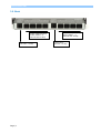
3. Diagram
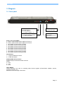
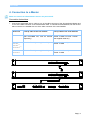
3.1. Front panel
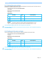
LEDs
A = Power supply A
B = Power supply B
1 - 8 = Status of outlets 1 - 8
SUB-D9F Connector
Terminal connection
Dip Switches
1 - 4: physical address of device
RJ45 Connectors
xBus RS485
Cascading connection
5 - 6: xBus termination
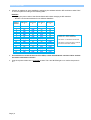
A B 1 2 3 4 5 6 7 8 (LEDs)
A Green. Lights up when power applied on Group A
B Green. Lights up when power applied on Group B
1 Red. Status of power outlet 1 (On/Off)
2 Red. Status of power outlet 2 (On/Off)
3 Red. Status of power outlet 3 (On/Off)
4 Red. Status of power outlet 4 (On/Off)
5 Red. Status of power outlet 5 (On/Off)
6 Red. Status of power outlet 6 (On/Off)
7 Red. Status of power outlet 7 (On/Off)
8 Red. Status of power outlet 8 (On/Off)
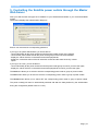
Dip Switches
1 - 4: physical address of device
5 - 6: xBus termination
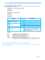
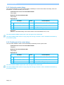
RS232 (SUB-D 9F Connector)
RS232 serial port with DB-9 female connector
Pinout
2 = RxD
3 = TxD
5 = Gnd
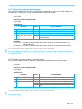
xBus (RS485)
These connectors are used for cascading xBus devices together (ePowerSwitch Satellite, sensors,
extension modules, etc.).
Maximal TOTAL line length: 200 meters
Page | 6