1
OPERATING INSTRUCTIONS FOR GAMBIT ADC2 24Bit / 192kHz A/D CONVERTER
POW-r Dither
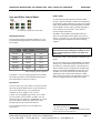
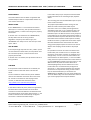
Sync and Dither Control Panel
Fig. 6 ADC2 Sync and Dither Control Panel
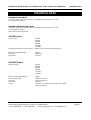
Sampling Frequency
If the analogue inputs are selected (“digital in” is not
lit), the A/D sampling frequency can be set in the sync
source block:
Sampling
Frequency
OPERATION
44.1 / 48 kHz
key
fs x 2 / fs x 4 key
44.1 kHz
44.1 kHz
none
48.0 kHz
48 kHz
none
88.2 kHz
44.1 kHz
sf x 2
96.0 kHz
48 kHz
sf x 2
176.4 kHz
44.1 kHz
sf x 4
192.0 kHz
48 kHz
sf x 4
Table 1 Samplig Frequency Selection
If “digital in” is lit, the sampling frequency keys display
the sampling frequency of the AES/EBU input signal in
the same fashion as is shown in Table 1.
To requantize the input signal from 24bit to 16bit
format, a special technique is used to avoid distortion,
called dithering. Many dithering schemes are available
today, both professional and homebrewed. The ADC2
uses the POW-r scheme, which is widely regarded as
2
one of the best, if not the best , and is used in a
variety of digital equipment.
The POW-r scheme offers three different presets
which can be selected with the dither keys “pow-r 1”,
“pow-r 2” and “pow-r 3”. The choice should be based
on listening tests and preference of the recording
engineer.
3
Dithering is in “auto black” mode: if digital zero is
detected at the ouput, dithering is switched off. This
ensures that programme breaks are not filled with
dither noise.
“Auto black” mode is not available for analogue input
signals.
Also note the effect of the “DITHER MODE” dip switch
setting in Fig. 1 ADC2 Block Diagram Schematic. If the
dip switch is in the down position, requantisation to
16 bit and dithering is only applied to the S/PDIF RCA
output, whereas the AES/EBU XLR output still carries
all 24bits. This mode is useful for live recording to a
24bit device with simultaneous backup to a 16bit
device (like DAT or CD-R). If the dip switch is in the up
position, all digital outputs are dithered to 16bits.
Sync Source
As can be seen in Fig. 1, the ADC2 can be synchronized
externally by other digital devices. It has two external
sync inputs. External sync is only available for
analogue inputs, ie “digital in” key is not lit.
If “AES” is lit, the AES/EBU signal at the “DI 1 / SYNC”
input is used for synchronization. If “BNC” is lit, the
wordclock signal connected to “WORDSYNC in” is used
for synchronization. Both sync inputs have a loopthrough ouput to syncronize other devices.
If none of these two keys are lit, the ADC2 uses
internal sync.
2
For reviews of POW-r visit www.weiss.ch
3
The term “black” comes from digital image formats, where
black is represented by the value zero.
Daniel Weiss Engineering Ltd., Florastr. 42, CH-8610 Uster
+41 1 940 20 06 +41 1 940 22 14 http://www.weiss. ch [email protected]
Page 7