
1
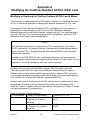
TeleFlow™
Standard ACCOL
Load
(NOTE: This manual was formerly entitled ’TeleFlow™
Standard ACCOL Load and Menus', TMS menus are now
documented in appendices of the TeleFlow hardware manual.)
&VMWXSP&EFGSGO
D4087 Issue:
December, 2000
The information in this document is subject to change without notice.
Every effort has been made to supply complete and accurate information.
However, Bristol Babcock assumes no responsibility for any errors that
may appear in this document.
Bristol Babcock does not guarantee the accuracy, sufficiency or suitability
of the software delivered herewith. The Customer shall inspect and test
such software and other materials to his/her satisfaction before using
them with important data.
There are no warranties, expressed or implied, including those of
merchantability and fitness for a particular purpose, concerning the
software and other materials delivered herewith.
Request for Additional Instructions
Additional copies of instruction manuals may be ordered from the address
below per attention of the Sales Order Processing Department. List the
instruction book numbers or give the complete model, serial or software
version number. Furnish a return address that includes the name of the
person who will receive the material. Billing for extra copies will be
according to current pricing schedules.
ACCOL is a trademark and Bristol is a registered trademark of Bristol
Babcock. Other trademarks or copyrighted products mentioned in this
document are for information only, and belong to their respective
companies, or trademark holders.
Copyright (c) 2000, Bristol Babcock, 1100 Buckingham St., Watertown,
CT 06795. No part of this manual may be reproduced in any form without
the express written permission of Bristol Babcock.
A Few Words About Bristol Babcock
For over 100 years, Bristol has been providing innovative solutions for the measurement and control industry.
Our product lines range from simple analog chart recorders, to sophisticated digital remote process
controllers and flow computers, all the way to turnkey SCADA systems. Over the years, we have become a
leading supplier to the electronic gas measurement, water purification, and wastewater treatment industries.
On off-shore oil platforms, on natural gas pipelines, and maybe even at your local water company, there are
Bristol Babcock instruments, controllers, and systems running year-in and year-out to provide accurate and
timely data to our customers.
Getting Additional Information
In addition to the information contained in this manual, you may receive additional assistance in using this
product from the following sources:
Contacting Bristol Babcock Directly
Bristol Babcock’s world headquarters are located at 1100 Buckingham Street, Watertown, Connecticut 06795
USA. Our main phone numbers are:
(860) 945-2200
(860) 945-2213 (FAX)
Regular office hours are Monday through Friday, 8:00AM to 4:30PM Eastern Time, excluding holidays, and
scheduled factory shutdowns. During other hours, callers may leave messages using Bristol’s voice mail
system.
Telephone Support - Technical Questions
During regular business hours, Bristol Babcock’s Application Support Group can provide telephone support
for your technical questions.
For technical questions regarding the TeleFlow Standard ACCOL load, other ACCOL products, Open BSI
Utilities, as well as Bristol’s Enterprise Server®/ Enterprise Workstation® products, call (860) 945-2286.
For technical questions about the TeleFlow unit, and other Network 3000 hardware call (860) 945-2502.
For technical questions about ControlWave call (860) 945-2244 or (860) 945-2286.
For technical questions regarding Bristol’s OpenEnterprise product, call (860) 945-2501 or e-mail
[email protected]
You can e-mail the Application Support Group at: [email protected]
i
The Application Support Group also maintains a bulletin board for downloading software updates to
customers. To access the bulletin board, dial (860) 945-2251 (Modem settings: 14.4K baud maximum, No
parity, 8 data bits, 1 Stop bit.)
For assistance in interfacing Bristol Babcock hardware to radios, contact Communication Technologies in
Orlando, FL at (407) 629-9463 or (407) 629-9464.
Telephone Support - Non-Technical Questions, Product Orders, etc.
Questions of a non-technical nature (product orders, literature requests, price and delivery information, etc.)
should be directed to the nearest regional sales office (listed below) or to your local Bristol sales office or
Bristol-authorized sales representative.
U.S. Regional Sales Offices
Northeast (Watertown) (860) 945-2262
Southeast (Birmingham) (205) 980-2010
Midwest (Chicago) (630) 571-6052
Western (Los Angeles) (909) 923-8488
Southwest (Houston) (713) 685-6200
Principal International Sales Offices:
Bristol Babcock Ltd (UK): (441) 562-820-001
Bristol Babcock, Canada: (416) 675-3820
Bristol Meci SA (France): (33) 2-5421-4074
Bristol Digital Sys. Australasia Pty. Ltd. 61 8-9455-9955
BBI, S.A. de C.V. (Mexico) (525) 254-2131
Please call the main Bristol Babcock number (860-945-2200) if you are unsure which office covers your
particular area.
Visit our Site on the World Wide Web
For general information about Bristol Babcock and its products, please visit our site on the World Wide Web
at: www.bristolbabcock.com
Training Courses
Bristol Babcock’s Training Department offers a wide variety of courses in Bristol hardware and software at
our Watertown, Connecticut headquarters, and at selected Bristol regional offices, throughout the year.
Contact our Training Department at (860) 945-2343 for course information, enrollment, pricing, and
schedules.
ii
Who Should Read This Document?
This document is intended to be read by EGM 3530-xx TeleFlow users who are
using the standard software accompanying the TeleFlow™.
It assumes that the TeleFlow™ has been installed, and that all network cabling has
been connected and tested.
EQUIPMENT APPLICATION WARNING
The user should note that a failure of this instrument or system, for whatever
reason, may leave an operating process without protection. Depending upon the
application, this could result in possible damage to property or injury to persons.
It is suggested that the purchaser review the need for additional backup
equipment or provide alternate means of protection such as alarm devices, output
limiting, fail-safe valves, relief valves, emergency shutoffs, emergency switches,
etc. If additional information is required, the purchaser is advised to contact
Bristol Babcock.
This document assumes familiarity with the following subjects:
"
"
"
The requirements of their particular process or application.
ACCOL programming. Anyone modifying the TeleFlow™ standard ACCOL
load should be an experienced ACCOL programmer. For more information,
consider attending an ACCOL training class. Also see An Introduction to
ACCOL (document# D4056), the ACCOL Workbench User Manual
(document# D4051), and the ACCOL II Reference Manual (document#
D4044).
Universal Operator Interface (UOI) software. Anyone attempting to use the
standard TMS menus must be familiar with the UOI software tools. See the
UOI Configuration Manual (document# D5074) and the UOI Operator
Manual (document# D5075) for details.
iii
iv
Table of Contents
Chapter 1 - Introduction
1-1
Chapter 2 - TeleFlow™ Standard ACCOL Load
2-1
Appendix A - Modifying the TeleFlow™ Standard ACCOL Load A-1
v
BLANK PAGE
Chapter 1 - Introduction
What is the TeleFlow™ Standard ACCOL Load?
The TeleFlow™ Standard ACCOL Load is included on the TeleFlow™ diskette.
This ACCOL load contains ACCOL modules specifically configured to perform
various natural gas calculations using a standard I/O setup. It is discussed in detail
in Chapter 2 of this manual.
The TeleFlow™ Standard ACCOL Load is used in conjunction with the TeleFlow
Menu System (TMS) menus (discussed below), and the TeleFlow™ EGM 3530
Electronic Gas Measurement Computer.
For information on the TeleFlow™ Electronic Gas Measurement Computer, see the
CI-3530-xx hardware manual for your particular TeleFlow™ model.
What Are the TMS Menus?
The TeleFlow Menu System (TMS) menus, which may be run on the PC, are
specifically configured to collect and display data from the TeleFlow Standard
ACCOL Load. These menus are discussed in detail in Appendix F of the appropriate
TeleFlow™ hardware manual.
Modifying or Replacing the TeleFlow Standard ACCOL Load
The TeleFlow is a download-able ACCOL device, therefore, the TeleFlow Standard
ACCOL Load can be modified or replaced with another compatible ACCOL load.
(See Appendix A for some notes about modifying the TeleFlow Standard ACCOL
Load.) For example, if the TeleFlow Standard ACCOL Load does not fit your
particular application, you may modify the .ACC file in ACCOL Workbench
software (available separately from Bristol Babcock,) re-build the ACL file, and
download it into the TeleFlow . For more information on ACCOL Workbench, see
the ACCOL Workbench User Manual (document# D4051).
Be aware, also, that the TeleFlow Menu System (TMS) is closely tied to the
TeleFlow Standard ACCOL Load. If you modify the standard load, or create a
different load, you will need to modify the menus which make up TMS, using the
UOI program (available separately from Bristol Babcock). For more information on
UOI, see the UOI Configuration Manual (document# D5074).
TeleFlow™
1-1
Standard ACCOL Load
BLANK PAGE
Chapter 2 - TeleFlow Standard ACCOL Load
Overview
The TeleFlow Standard load is a an ACCOL load (ACL file) that is intended for use
in the EGM 3530 TeleFlow. This ACCOL load will compute gas flow rate, energy
rate and volume and energy totals for a single Orifice meter run. Flow calculations
and data storage will be done according to the requirements of Chapter 21 of the
American Petroleum Institute Manual of Petroleum Measurement Standards
(MPMS).
The TeleFlow Standard load supports the following functions:
"
"
"
"
"
"
"
"
"
"
"
"
"
"
"
Gas flow calculations per AGA3 (1985) or AGA3 (1992) for an Orifice meter.
Compressibility (Zf and Zb) per AGA8Detail or AGA8Gross when AGA3 (1992) is
used.
Supercompressibility (Fpv) per NX-19 when AGA3 (1985) is used.
Energy (Btu/ft3) per AGA5 or from a fixed value.
Raise/Lower flow rate control using a PID3TERM module and two Discrete
outputs.
Pulse output on DO#1 with rate proportional to volume for odorant injection.
An Audit Trail holding 200 events and 200 alarms for a total of 400 entries.
A Daily Archive file containing 35 days of Daily historical information.
A Periodic Archive file containing 35 days of Hourly historical information.
A Trend Archive file containing 8 days of 15 minute trend information (can be
disabled).
Support of a local 2 line display (LCD) and single push-button.
Local and Network communications.
Backflow detection and alarming.
Nomination alarm settings.
Input sampling, averaging and Extension calculation every second.
TeleFlow™
2-1
Standard ACCOL Load
Chapter 2 - TeleFlow Standard ACCOL Load
"
"
"
"
"
Configurable 1, 2, 5, 15, and 60 second calculation interval.
Pulse counting and scaling.
Configurable automatic dial-out on alarm occurrence. (NOT YET SUPPORTED)
Control of an external radio.
Battery charge regulator.
NOTE:
The EGM 3530 only supports a subset of the ACCOL module library thus some
ACCOL modules will not operate. See the ’Hardware and Software Requirements’
section of the ACCOL II Reference Manual (document# D4044) to find out which
modules are supported.
In addition, the EGM-3530 will not provide some functions that are common in
Bristol products; among these are Communication Statistics, Crash Blocks, On-line
Diagnostics, Task slip information, and Task rate information.
The main task of the TeleFlow Standard Load executes every second and 'wakes up'
the hardware (out of low-power mode) and collects 'live' Differential Pressure (DP),
Static Pressure (P) and Temperature (T) input data and status data from the
internal sensor conditioning circuitry. In accordance with the API MPMS, Chapter
21 requirements, these are averaged over the configured Calculation interval for
use in the flow calculations; averaging is 'flow-dependent' in that it only occurs
when the DP value is above a configured 'cutoff' level.
The live DP and P values are used to compute an Extension value (the square root
of the product of the live DP and P) every second; Extension values are added over
the Calculation interval, which can be configured at 1, 2, 5, 15 or 60 seconds. The
interval is configured by the user to obtain the best balance of power consumption
and calculation rate. If a calculation is not scheduled the task completes and the
hardware re-enters sleep mode.
At the end of a Calculation interval a full flow calculation is performed. Averaged
input values for the interval are used in the FPV, AGA8Detail, or AGA8Gross
modules to obtain gas compressibility factors. These are then used in an AGA3
(1985 or 1992) equation to compute the flow rate in MSCF per hour. The Extension
used in the AGA3 calculation is an average Extension for the Calculation interval
TeleFlow™
2-2
Standard ACCOL Load
Chapter 2 - TeleFlow Standard ACCOL Load
obtained by summing the Extensions computed every second during the interval
and dividing by the number of Extension values summed. The Extension sum is
then cleared and averages are reset for another Calculation interval.
There are several conditions, which force the Calculation interval to be 1 second as
follows.
1. When the Local communications port is in use.
2. When the LCD Display is active (i.e scrolling data for the operator).
3. When PID flow control is active and the flow rate is not within 2% of the
setpoint.
4. When the Network Port is active (Carrier Detect is high)
In addition to the input signal averages for the Calculation interval, another set of
input averages is maintained for each full log period (hour or 15 min) and day;
these averages are stored in the Archive for that log.
Process Inputs: Differential Pressure (DP), Static Pressure (P),
Temperature (T)
The process inputs used for the Gas Flow computations are Differential Pressure
(DP), Static Pressure (P), and Temperature (T). The DP and P come from the
internal, multivariable sensor; the Temperature is measured by an RTD probe.
Each second, these values are acquired from the internal sensor and placed in the
'live data' signals.
Input Averaging
The process inputs DP, P and T 'live data' values are averaged over the configured
Calculation interval; the average is a 'flow-dependent time-weighted' value in
accordance with MPMS requirements. The averages are calculated for the periods
of time when the DP is above the user configured Cutoff level. When there is no
flow for the entire Calculation interval, straight arithmetic averages are calculated
for the Static Pressure and Temperature. At the end of each Calculation interval
the calculated averages are stored in the 'in-use' signals and used to calculate flow
rate and volume.
Separate averages of DP, P, and T are maintained for each log period (hour or 15
min) and the day.
TeleFlow™
2-3
Standard ACCOL Load
Chapter 2 - TeleFlow Standard ACCOL Load
Input Override and Calibration Mode
The 'in use' signals can be 'frozen' at their current value by setting their standard
ACCOL Control Inhibit (CI) on. When an 'in-use' signal (DP, P, or T) is in 'CI' mode,
the 'live data' signal continues to reflect the current value from the internal sensor,
however, the 'in-use' signal is no longer updated and remains 'frozen' at its current
value. Input averaging continues to be performed using the 'in-use' value rather
than the 'live data' value.
While the 'in-use' signals are in CI mode the Operator can enter an 'Override' value
into the signal for use in the input averaging and Gas Flow calculation.
When the CALIB (Calibration mode) signal is set ON all the DP, P, and T 'in-use'
signals are simultaneously placed in CI mode.
Input Alarms
The process inputs DP, P, and T are alarm signals with the following default alarm
limits:
DP
P
T
Low
High
LowLow
HighHigh
LDb
HDb
10
100
50
250
1500
150
0
0
32
300
2000
250
3
10
3
10
50
10
Digital Inputs
Inputs 1 and 2 are free for general use and can be used as alarm inputs or
monitoring inputs. The default alarm condition is the ON state, i.e. the alarm
occurs when the input enters its ON state. These inputs are updated once a second.
Digital Outputs
The discrete outputs are shared by the Flow control and Sampler function.
When Flow control is enabled:
DO 1 - Raise pulse output.
DO 2 - Lower pulse output.
TeleFlow™
2-4
Standard ACCOL Load
Chapter 2 - TeleFlow Standard ACCOL Load
When Sampler output is enabled:
DO 1 - Pulse output based on volume (to drive an external totalizer or sampler).
DO 2 - general-purpose output.
Sampler logic has a default volume of 100 mscf and a default pulse width of 1
second.
Flow control has priority for the discrete outputs so that if both Sampler output and
Flow control are enabled, Sampler will be shut off and Flow control will use the
outputs.
Auxiliary Analog Input
This input is scaled for 1 to 5 volts, but up to 16 volts can be applied; it can be used
as an alarm or monitoring input. Signals are provided that allow this input to be
scaled into other units. Voltages higher than 5 volts are scaled accordingly, i.e. 10
volts=200%, 15 volts=300%, etc.
The default scaling is:
Zero
Full scale
= 0.0 % (1 volt input)
= 100.0 % (5 volts input)
Default alarm limits are:
Low
10%
High
100%
Lo-lo
0%
Hi-hi
150%
LDb
3%
HDb
10%
This input is updated once each calculation interval.
Pulse Input
This input accepts pulses at rates up to 5,000 Hz and keeps a running pulse total
and frequency value. A scaling factor can be configured to convert pulses into other
units i.e., if each pulse is the equivalent of 5 gallons a scaling factor of 5 makes the
total be in gallon units. The frequency and total can be read in 'raw' units (counts
and Hertz) and also in scaled units. Default pulse scaling factor is 1.0.
TeleFlow™
2-5
Standard ACCOL Load
Chapter 2 - TeleFlow Standard ACCOL Load
Communications Port Assignments
PORT #1 - Pseudo-slave local port, 19200 bps.
PORT #2 - BSAP network port, 9600 bps.
The baud rate and the RTS/CTS delay may be changed on-line.
Communication Port Usage
The Local port is used for local configuration and data collection. It usually connects
to a PC or Laptop that is running a user-interface software package like TMS or
UOI. The Local port will respond to any address; therefore it CANNOT be used in a
multi-drop connection. Only the Network port can be multi-dropped (with the
necessary external RS-485 converters).
The Network port is used generally for data collection via Bristol Peer-to-peer
messages coming from another Bristol device such as a Data Concentrator; for this
kind of data collection a number of defined lists are provided as well as Slave
modules for each list. This port can also be used for data collection or configuration
by software such as Open BSI, UOI, TMS, or other third party BSAP protocol based
communication systems. The Network port will not respond to messages unless its
DCD input is high.
Gas Flow Calculations
Either the 1985 or 1992 AGA3 calculations can be selected; 1985 calculations are
suitable for both Flange and Pipe taps; 1992 calculations only use Flange taps.
AGA3 calculations are performed at the end of the configured Calculation interval.
(Note: Maximum power conservation is achieved by using the longest calculation
cycle.)
The Calculation interval is user configurable at 1, 2, 5, 15, or 60 seconds. Under
certain conditions the Calculation interval is forced to 1 second. These conditions
are:
The Local Communications port is in use.
The LCD Display button has been pushed and the unit is scrolling the Display List.
The unit is in 'charge regulation' mode
TeleFlow™
2-6
Standard ACCOL Load
Chapter 2 - TeleFlow Standard ACCOL Load
The flow control is active and not close to the setpoint.
Super-compressibility (Fpv) and Compressibility ( Zs, Zb, Zf)
When the 1985 AGA3 calculation is selected, the Super-compressibility (Fpv) value
is calculated using the NX-19 equations. When the 1992 AGA3 calculation is used
the Flowing (Zf) and Base (Zb) compressibility factors are calculated using either the
AGA8Detail or AGA8Gross module. The AGA8Gross module provides either the
G,C,N or HV, G, C modes.
If the Base Pressure or Base Temperature differ from Standard conditions (14.73
o
psia, 60 F) and the 1992 AGA3 calculation is in use, an AGA8Detail or AGA8Gross
module will be executed to calculate standard compressibility Zs for the defined gas
composition. The calculation of Zs will be done once per minute or whenever a
related gas constant changes.
Flow Rates
Gas Flow-rate is calculated in mscf/hr using an AGA3Term module if the 1985
calculation is selected, otherwise the AGA3Iter module (1992 calculation) is used.
Because of MPMS requirements the Extension value is supplied to these modules
externally.
Flow rate in mscf/hr is converted to mscf/day and is available for reading.
Flow Rate Alarm
The flow rate signal is an alarm signal with default alarm limits (in mscf/hr):
Low
High
Lo-lo
Hi-hi
LDb
HDb
0
3000
0
5000
50
50
Flow Volume Totals
At the end of each Calculation interval the volume for that interval is added to
totals for the hour, day, current month and 'running' totalized volume. At the end of
each hour, day, and month the accumulated volume for that period is stored and
TeleFlow™
2-7
Standard ACCOL Load
Chapter 2 - TeleFlow Standard ACCOL Load
the total cleared for the next period. The running total is not cleared; it accumulates
to 10 million at which point it rolls over to zero and continues accumulating.
Averaged Extension
The average value of the Extension ( square root of the product of process DP and
absolute Static Pressure) is computed for each log period (hour or 15 min) and for
the day and saved in an archive. This average is maintained separately from the
value used in calculating the flow volume for a Calculation interval.
Back Flow
The time spent in a Back Flow condition is totaled for the current and previous day
and an alarm is generated if the condition exceeds a user-specified limit. As each
input sample is processed, the DP reading is examined to see if a Back Flow
condition is present.; (i.e. DP is less than 0.0 and the absolute value of DP is greater
than the DP Cutoff). If a Back Flow condition is detected, a Back Flow timer is
started. If the Back Flow condition remains in effect for a user configured number
of seconds, a Logical Alarm signal is turned 'ON'.
The amount of time during which a Back Flow condition has been detected for the
current day is accumulated in an Analog signal. At the end of the contract day, the
value in this signal is transferred into the previous day's Back Flow Time signal
and the signal is set to 0.0. All intervals of Back Flow are accumulated,
independent of the alarm state. (i.e. Short durations of Back Flow, less than the
Back Flow timer, are accumulated even though the Back Flow Alarm is not turned
'ON'.)
Gas Energy Calculations
Gas flow volume for a Calculation interval is converted to energy in MMBTU (i.e.
DekaTherms; a DekaTherm is 10 million Btu) by multiplying by a Heating value in
BTU/cu.ft. and dividing by 10 million; the Heating value can come from a fixed
value or from an AGA5 calculation.
The energy for the interval is summed to produce an energy total in MMBTU for
the each hour and day, and for the current month.
Flow rate is converted to energy rate in MMBTU/hr.
TeleFlow™
2-8
Standard ACCOL Load
Chapter 2 - TeleFlow Standard ACCOL Load
Low-Flow Cut-OFF
The 'live' Differential pressure is always compared to a CUTOFF signal set in
inches of water. When the DP value drops below the value of the CUTOFF signal,
flow calculation will cease and the calculated flow-rate will be zero. Default cutoff is
0.25 inches of H2O.
Flow Time
While the DP is above the Cutoff limit the unit will accumulate a flow-time count
in minutes for the hour and day. In a backflow condition a separate backflow time
is accumulated.
Archive Files
Periodic Archive
The interval is 1 hour. At the end of the interval, the information shown below is
written into a periodic archive file. If log break is enabled, these values are written
when a configuration value changes.
DATE/TIME
LOCAL SEQUENCE NUMBER
GLOBAL SEQUENCE NUMBER
AVERAGE DP
AVERAGE STATIC PRESSURE
AVERAGE FLOWING TEMP.
FLOW TIME
AVERAGE EXTENSION
ACCUMULATED VOLUME
ACCUMULATED ENERGY
AVERAGE AUXILIARY INPUT
INH2O
PSIG
DEGF
MINS
MSCF
MMBTU
%
Daily Archive
At the end of every day the information shown below is written into a daily archive
TeleFlow™
2-9
Standard ACCOL Load
Chapter 2 - TeleFlow Standard ACCOL Load
file.
DATE/TIME
LOCAL SEQUENCE NUMBER
GLOBAL SEQUENCE NUMBER
AVERAGE DP
AVERAGE STATIC PRESSURE
AVERAGE FLOWING TEMP.
FLOW TIME
AVERAGE EXTENSION
ACCUMULATED VOLUME
ACCUMULATED ENERGY
AVERAGE AUXILIARY INPUT
INH2O
PSIG
DEGF
MINS
MSCF
MMBTU
%
Trend Archive
If the Trend log is enabled then every 15 minutes the live (not averaged) input
values are written to a trend archive as shown below.
DATE/TIME
LOCAL SEQUENCE NUMBER
GLOBAL SEQUENCE NUMBER
DIFF. PRESSURE
STATIC PRESSURE
FLOWING TEMP.
INH2O
PSIG
DEGF
Log Break
When the Log Break option is enabled archive log-break will occur when the Orifice
plate size or other flow-related constant is changed.
Flow Control
Raise/lower Flow-rate control is achieved using a PID3TERM Module. The Flow
Controller uses a FLOW SETPOINT signal and the calculated flow rate signal as
inputs to the PID3TERM module, the output of which generates raise/lower pulses
on the discrete outputs (Raise on DO#1, Lower on DO#2).
Default settings are:
TeleFlow™
2-10
Standard ACCOL Load
Chapter 2 - TeleFlow Standard ACCOL Load
Gain
Integral
Derivative
Deadband
Valve travel
Pulse width
Max rate
1
1 repeat/min
0 mins
0
30 secs
1 sec
5000 mscf/hr
Radio Control
Two radio control functions are available; Scheduling and Sensing (also called 'Fast
radio'). Radio Scheduling is used to conserve battery power by allowing the radio to
be powered up for a short time every day in expectation of receiving a message from
a remote 'host' during that time.
If Radio Scheduling is enabled, the system will turn ON the radio at a defined time
(an hour of the day) and keep it on for a defined length of time, usually in a period
of minutes. A user-configured 'listen' timer is also started so that if no messages are
received while the timer is running the radio will turn OFF to save power. The
radio can also be activated manually for testing via the local port. Radio power is
controlled using a system signal that turns an auxiliary power output ON or OFF.
If Radio Sensing is enabled the system will turn the radio on at a defined time (an
hour of the day) and begin a sequence in which the radio is turned ON every so
many seconds but for 'listen' time intervals less than 1 second. It continues this
sequence until the defined 'stop' hour is reached. If a message is received while the
radio is ON the system will keep the radio ON, process the message and respond.
After every response the radio remains ON for one more 'listen' time, after which it
is shut OFF.
Both radio control functions can be active simultaneously.
Modem Dial-Out (THIS FUNCTION IS NOT YET SUPPORTED)
This feature makes use of the ACCOL Slave Auto-dial function. When DIALOUT is
enabled and a trigger condition is satisfied the load will automatically dial a phone
number (the modem option must be installed) held in the Dial List. The number of
the Dial list is held in system signal #DIAL.001. Up to 13 different trigger
conditions can be armed to initiate the call. Program logic examines the state of the
signal associated with an 'arm' signal and, should it be in an Alarm state, sets a
non-zero value into the Dial Enable signal in the Dial List to start the call. The dial
TeleFlow™
2-11
Standard ACCOL Load
Chapter 2 - TeleFlow Standard ACCOL Load
commands sent to the modem (i.e. initialization, phone number) are defined by
signals in the Dial list.
The use of the modem dial out function implies that the called device has been set
up to 'know' that it should poll for alarms after it answers the call and then hangup.
Dialing logic will dial the first phone number three times and then dial a second
number three times, the combination constituting one 'dial-attempt'. To conserve
power the maximum number of attempts per hour is two; this value can be
configured up to 9 by the user.
Battery Charge Control
Signals are provided to allow charge regulator setup and control for either a 6 or 12
volt battery. Should the charge regulator detect battery overcharge, an alarm
occurs, and a shunt regulator is activated which deactivates the solar panel,
thereby preventing an overcharge condition.
Power and Load Status Alarms
The main voltage value will be held in an alarm signal with default limits (in Volts)
as follows:
Low
High
Lo-lo
Hi-hi
LDb
HDb
5.75
16.0
5.5
16.5
.5
.5
A number of 'load status' logical alarms are provided as follows:
Backflow alarm
Low DP (cutoff
)
Backup battery
External battery overcharge
AGA8 Calculation error
Floating-point math error
System self-check
Sensor conversion
Sensor checksum
TeleFlow™
backflow is detected
Dp below cutoff
low RAM backup battery
excess voltage into the external battery
final value is approximate
system problem
conversion error
compensation has changed
2-12
Standard ACCOL Load
Chapter 2 - TeleFlow Standard ACCOL Load
Audit/Event Log
The EAUDIT module (in Task 0) is set up to collect both alarms and events, with
event signals defined by the signals in list 23. The module is defined with enough
space for 400 alarms and events, and the module operates such that 200 alarms and
200 events are kept separate until the Audit log is collected. This design prevents a
toggling alarm or event from filling the entire alarm/event log buffer to the
exclusion of all other entries.
Gas Data Lists For Master Node Access
Data lists are provided to support the gathering of gas data from a master node via
the Network port using Bristol peer-to-peer messages. The associated slave point
number is shown. Lists without slave points can only be read using Open BSI
DataView.
LIST 10 Full Configuration
Firmware revision (progrev)
Unit ID
Meter ID
Meter number
Alarm report format
Alarm report format 1
Display alarms
Flow equation
Base pressure
Base temperature
Pipe material
Orifice material
AGA8 Method
AGA8 Gross mode
Contract hour
Pipe diameter
Pipe ref temperature
Tap location
Tap type
Orifice diameter
Orifice ref temperature
Low DP cutoff
TeleFlow™
2-13
Standard ACCOL Load
Chapter 2 - TeleFlow Standard ACCOL Load
DP Full scale pressure
DP Pressure zero
SP Full scale pressure
SP Pressure zero
Temperature full scale
Temperature zero
Rate lo-lo
Rate lo
Rate hi
Rate hi-hi
Rate hi deadband
Rate lo deadband
DP lo-lo
DP lo
DP hi
DP hi-hi
DP hi deadband
DP lo deadband
SP lo-lo
SP lo
SP hi
SP hi-hi
SP hi deadband
SP lo deadband
Temp lo-lo
Temp lo
Temp hi
Temp hi-hi
Temp hi deadband
Temp lo deadband
Batt lo-lo
Batt lo
Batt hi
Batt hi-hi
Batt hi deadband
Batt lo deadband
Barometric pressure
Specific heat ratio
Heating value fixed
Heating value source
Specific gravity
Gravity type
Viscosity
CH4
TeleFlow™
2-14
Standard ACCOL Load
Chapter 2 - TeleFlow Standard ACCOL Load
N2
CO2
C2
C3
H2O
H2S
H2
CO
O2
IC4
NC4
IC5
NC5
C6
C7
C8
C9
C10
HE
AR
Sampler enable
Sampler volume
Sampler pulse width
Flow controller enable
Valve limit
Flow setpoint
Flow deadband
Gain
Integral
Derivative
Max flow rate
Valve travel time
Flow calculation interval
Periodic log interval
Break on change
Trending log enable
RTS/CTS mode
RTS delay
Auxiliary power default
Radio scheduling enable
Radio listen time
Radio comm. timeout
Radio start hour
Radio stop hour
TeleFlow™
2-15
Standard ACCOL Load
Chapter 2 - TeleFlow Standard ACCOL Load
Radio local comm. time
Radio local timeout
Radio time per node
Radio time per group
Radio minute offset into hour
Nomination enable
Nomination unit
Nomination mode
Nomination stop mode
Nomination Daily mode
Nomination Alarm dialout
Nomination Alarm percent
Next start date
Next start hour
Next stop date
Next stop hour
Demand enable
Demand interval
Demand duration
Demand start hour
Demand end hour
Off/On
MSCF/MMBTU
Fast/PID
Off/On
Off/On
0 - 100
LIST 11 Calculated Data - Slave Point 1
Flow Rate
Beta Ratio
Ev
Cd
Zs
Zb
Zf
Y
Extension
C-prime
LIST 12 Configuration #1 - Slave Point 2
Orifice Diameter
Pipe Diameter
Specific Gravity
Heating Value
Barometric Pressure
Base Pressure
TeleFlow™
.250" to 31"
2" to 31"
2-16
0
0
Standard ACCOL Load
Chapter 2 - TeleFlow Standard ACCOL Load
Base Temperature
Flowing Viscosity
Ratio of Specific Heat
Tap Location
Tap Type
Dp Cutoff
LIST 13 Configuration #2 - Slave Point 3
Firmware version (progrev)
Meter Number
Flow Equation
1985/1992
Calculation Interval
Contract Hour
Logging Interval
Break Log option
Heat Value source
Gravity type
AGA8 Method
AGA8 Gross Mode
LIST 14 Controller - Slave Point 4
Sampler Enable
Sampler Volume
Sampler Duration
Flow Rate Control
Valve Limiting
Setpoint
Deadband
Gain
Integral
Derivative
Valve Travel Time
Maximum Flow Rate
Nomination enable
Nomination unit
Nomination mode
Nomination stop mode
Nomination Daily mode
Nomination Alarm dialout
Nomination Alarm percent
Next start date
TeleFlow™
On/Off
0 - 10000 MCF
1.0 Secs
Off/On
Off/On
0 MSCF
0
0-100
0-60 RPTS/Min 1
0-60 Min
0
1-30 SEC
30
5000 MSCF 5000
Off/On
MSCF/MMBTU
Fast/PID
Off/On
Off/On
0 - 100
2-17
Standard ACCOL Load
Chapter 2 - TeleFlow Standard ACCOL Load
Next start hour
Next stop date
Next stop hour
LIST 15 AGA8 Gross Config
Specific Gravity
Heating Value
CO2 content
Nitrogen content
AGA8 Gross Mode
Gravity type
LIST 16 AGA8 Detail Gas composition
Methane
Nitrogen
CO2
Ethane
Propane
H2O
H2S
H2
CO
O2
I-Butane
N-Butane
I-Pentane
N-Pentane
Hexane
Heptane
Octane
Nonane
Decane
Helium
Argon
LIST 17 AGA3 1985 Factors
Flow Rate
Beta Ratio
Fpb
TeleFlow™
2-18
Standard ACCOL Load
Chapter 2 - TeleFlow Standard ACCOL Load
Ftb
Fg
Ftf
Fa
Fr
Y
Fb
Fpv
C-prime
Extension
LIST 18 Communication configuration
Network port baud rate
CTS/RTS mode
RTS delay
Aux power default
Radio sched enable
Radio on-time
Radio listen time
Radio start hour
Radio end hour
Local on-time
Local listen time
Node time
Group time
Offset into hour
Demand enable
Demand interval
Demand duration
Demand start hour
Demand end hour
Dialout on an Alarm enable
Dial on Cutoff enable
Dial on Backflow enable
Dial on Transmitter fail enable
Dial on Backup battery low enable
Dial on Fl.Pt error enable
Dial on Selftest error enable
Dial on DP alarm enable
Dial on SP alarm enable
Dial on TF alarm enable
Dial on Flow rate alarm enable
Dial on Battery alarm enable
TeleFlow™
2-19
Standard ACCOL Load
Chapter 2 - TeleFlow Standard ACCOL Load
Dial on Auxiliary input alarm enable
Dial on Charger alarm enable
Dial on Nomination alarm enable
LIST 20 Live Data
Diff pressure
Static pressure
Temperature
Flow rate
Operator change
LIST 21 Rate and Volume - Slave Point 5
Flow rate
Flow rate @ Std
Energy rate
Daily flow rate
Flow time today
Volume today
Energy today
Flow time yesday
Volume yesday
Energy yesday
Volume this month
Energy this month
Volume totalizer
Energy totalizer
Volume last month
Energy last month
Scaled frequency
Scaled pulses today
Scaled pulses yesterday
Scaled pulses total
LIST 22 Inputs - Slave Point 6
Diff pressure
Static pressure
Temperature
System power volts
Power input 1 volts
Power input 2 volts
TeleFlow™
2-20
Standard ACCOL Load
Chapter 2 - TeleFlow Standard ACCOL Load
Backup battery volts
PC board temperature
Auxiliary input
Total pulses
Pulse Frequency
DO#1
DO#2
DI#1
DI#2
LIST 50 LCD Display list
Meter ID
System power
Aux input
Diff pressure
Flowing pressure
Temperature
Daily flow rate
Flow time today
Volume today
Volume yesday
Volume totalizer
TeleFlow™
2-21
Standard ACCOL Load
BLANK PAGE
Appendix A
Modifying the TeleFlow Standard ACCOL (TSA) Load
Modifying or Replacing the TeleFlow Standard ACCOL Load & Menus
The TeleFlow is a download-able ACCOL device, therefore, the TeleFlow Standard
ACCOL Load can be modified or replaced with another compatible ACCOL load.
For example, if the TeleFlow Standard ACCOL Load does not fit your particular
application, you may modify the .ACC file in ACCOL Workbench software
(available separately from Bristol Babcock,) re-build the ACL file, and download it
into the TeleFlow . For more information on ACCOL Workbench, see the ACCOL
Workbench User Manual (document# D4051).
NOTE:
The TeleFlow only supports a subset of the ACCOL module library thus some
ACCOL modules will not operate. See the 'Hardware and Software Requirements'
section of the ACCOL II Reference Manual (document# D4044) to find out which
modules are supported.
In addition, the EGM-3530 will not provide some functions that are common in
Bristol products; among these are Communication Statistics, Crash Blocks, On-line
Diagnostics, Task slip information, and Task rate information.
Be aware, also, that the TeleFlow Menu System (TMS) is closely tied to the
TeleFlow Standard ACCOL Load. If you modify the standard load, or create a
different load, you will need to modify the menus which make up TMS, using the
UOI program (available separately from Bristol Babcock). For more information on
UOI, see the UOI Configuration Manual (document# D5074).
Another restriction on modifying the ACCOL load is that the communication ports
and process I/O boards must be configured consistently with the design of the
TeleFlow. Table 1-1, below, shows the required port configuration; Table 1-2, shows
the required process I/O configuration.
Table 1-1 Process I/O Board Options
I/O Slot Number Process I/O Board Name
1
Digital Input Board with 2 or
10 points (or no board
installed)
2
Digital Output Board with 2
or 10 points (or no board
installed)
TeleFlow™
A-1
Syntax in ACC File
DI2
DI10
DO2
DO10
Standard ACCOL Load and Menus
Appendix A
Modifying the TeleFlow Standard ACCOL (TSA) Load
3
Analog Input Board with 1, 4,
5, or 8 points (or no board
installed)
4
High Speed Counter Board
with 1, 2, or 3 points (or no
board installed)
Analog Output Board with 1
point (or no board installed)
5
AI1
AI4
AI5
AI8
HSC1
HSC2
HSC3
AO1
Table 1-2 Communication Port Options
PORT
Port Type
A
Pseudo Slave
Baud Rate
300 - 38,400
B
Slave
300 - 38,400
C
Master
300 - 38,400
Notes
Asynchronous
Local Port
Asynchronous
Network Port
Asynchronous
Expanded I/O Port
NOTES ON POWER CONSUMPTION:
Assuming the Local Port is unused, the Network port is inactive, and the LCD
display is inactive, the 3530 will enter 'sleep' mode if it is not currently executing
an ACCOL task.
The larger the ACCOL load, the longer it takes to execute, and the longer the unit
'stays awake'. Load functions should be scheduled to run only when needed. This
means using logical signals as flags to control execution. Load tasks should be
carefully partitioned to execute only when necessary, so that maximum 'sleep' time
is obtained, thereby reducing power consumption.
TeleFlowTM
A-2
Standard ACCOL Load and Menus
READER RESPONSE FORM
Please help us make our documentation more useful to you! If you have a
complaint, a suggestion, or a correction regarding this manual, please tell us by
mailing this page with your comments. It’s the only way we know we’re doing our
job by giving you correct, complete, and useful documentation.
DOCUMENT NUMBER: D4087
TITLE: TeleFlow Standard ACCOL Load
ISSUE DATE: December, 2000
COMMENT/COMPLAINT:
______________________________________________________________________________
______________________________________________________________________________
______________________________________________________________________________
______________________________________________________________________________
______________________________________________________________________________
______________________________________________________________________________
______________________________________________________________________________
______________________________________________________________________________
______________________________________________________________________________
______________________________________________________________________________
______________________________________________________________________________
______________________________________________________________________________
______________________________________________________________________________
Mail or FAX this page to:
Bristol Babcock Inc.
1100 Buckingham Street
Watertown, CT 06795
FAX#: (860) 945-2213
Attn: Technical Publications Group, Dept. 610
RRF - 12/2000
&VMWXSP&EFGSGO-RG
an FKI company
1100 Buckingham Street
Watertown, CT 06795
Telephone: (860) 945-2200


![EnergyAccessOnline User Manual[1]](http://vs1.manualzilla.com/store/data/005906408_1-e15b8e64694c6ea91dc3f2c3109f09fc-150x150.png)