1
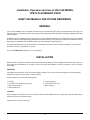
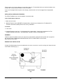
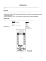
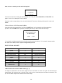
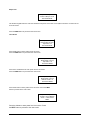
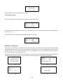
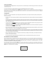
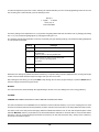
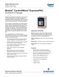
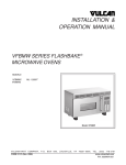
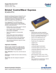
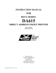
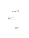
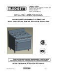
INSTALLATION &
OPERATION MANUAL
VFB12 ELECTRIC FLASHBAKE® OVEN
VFB12
VFB12
ML-114905
ML-114908
(Without Power Cord)
(With Power Cord)
VULCAN-HART COMPANY, P.O. BOX 696, LOUISVILLE, KY 40201-0696, TEL. (502) 778-2791
FORM 31020 (4-97)
TABLE OF CONTENTS
GENERAL
3
INSTALLATION
3
Unpacking
3
Location
3
Installation Codes and Standards
4
Assembly
4
Exhaust Duct Installation
4
Electrical Connections
5
Start-up Testing
6
OPERATION
8
Precautions
8
Controls
8
Programming the VFB12 FlashBake Oven
9
Recipe Options and Limits
10
Lamp Center and Outer Power Levels
10
Creating a "Standard" Cook Method Recipe.
11
Creating a Two-Step Cook Method Recipe.
13
Operating the VFB12 Oven
15
Cook Cycle Counter
17
Cooking Hints
17
High Through-Put Volume Consistency
17
Blower
18
Cleaning
18
Removing and Installing the Top Lamp Shield
20
MAINTENANCE
21
Inspecting the Oven
21
Fuses
21
Circuit Protectors
21
Lamp Replacement
21
TROUBLESHOOTING
©VULCAN,1997
22
-2-
Installation, Operation and Care of VULCAN MODEL
VFB12 FLASHBAKE® OVEN
KEEP THIS MANUAL FOR FUTURE REFERENCE
GENERAL
Your Vulcan FlashBake oven is a versatile oven that employs a revolutionary high quality, high-speed cooking technology. The
baking process is so fast that food retains its natural juices. Bread products brown and become crisp while vegetables retain their
color and texture.
FlashBake ovens use visible and infrared light energy to cook by radiative heat transfer. The infrared energy browns the surface
of the food, while the visible light energy penetrates and heats it internally. Using the proper combination of visible and infrared
light energy, the FlashBake oven provides efficient, high-speed baking and high quality food.
The VFB12 FlashBake oven may be ordered with a 6-foot (1829 mm) power cord for receptacle installation, or for direct line
electrical connection, single phase or 3 -phase.
These ovens MUST NOT be stacked one on top of another.
INSTALLATION
Before installing, verify that the electrical service agrees with the specifications on the rating plate located on the rear of the oven.
If the supply and specifications do not agree, do not proceed with the installation. Contact your dealer or Vulcan Company
immediately.
UNPACKING
Immediately after unpacking, check for possible shipping damage. If the oven is found to be damaged, save the packaging
material and contact the carrier within 15 days of delivery,
Check to make sure you have the following items:
1. Oven(1))
2. 16" (406.5 mm) stainless steel grill (1)
3. Upper lamp shield (1)
4. Owners Manual (1)
5. Cooking guide (1)
6. Lamp shield scraper (1)
7. Menu cards (3)
LOCATION
When deciding oven placement, be sure to consider clearance and available air for oven cooling. If the inlet air is obstructed or
heated, the oven will not operate properly.
Install the oven on a level counter top.
-3-
There must be a 3" (76 mm) clearance on each side of the oven. The area behind the oven around the blower must
be kept clear of obstructions and allow for free air circulation.
If your oven is equipped with the power cord and plug, ensure that the cord can be plugged into the appropriate
outlet.
INSTALLATION CODES AND STANDARDS
The VFB12 FlashBake oven must be installed in accordance with:
In the United States of America:
1. State and local codes.
2. National Electrical Code, ANSI/NFPA-70 (latest edition). Copies may be obtained from The National Fire
Protection Association, Batterymarch Park, Quincy, MA 02269.
In Canada:
1. Local codes.
2. Canadian Electrical Code, Part 2, CSA Standard C22.1 (latest edition). Copies may be obtained from The
Canadian Standard Association, 178 Rexdale Blvd., Rexdale, Ontario, Canada M9W 1R3.
ASSEMBLY
Install the upper lamp shield into the oven cavity. Be sure the shield is pushed all the way back and is lying flat in
the channels. Refer to REMOVING AND INSTALLING THE TOP LAMP SHIELD in this manual.
Place the grill on the rollers.
EXHAUST DUCT INSTALLATION
A length of flexible exhaust duct may be attached to the oven to vent hot air out of the cooking area. Attach the duct
to the blower assembly (Fig. 1).
Fig.1
-4-
The other end of the duct can be vented into an existing hood, or to the outside in a manner consistent with local
building codes.
The exhaust duct must not be less than 4" (101.5 mm) in diameter, and a recommended maximum length of 4 to 6
feet (1219-1829 mm) , depending on operating conditions. The duct should be made of metal suitable for high
temperature use. Be sure there are no bends in the duct that will restrict air flow. Depending on the length of
the duct required, it may be necessary to have a supplementary exhaust system to ensure adequate air flow.
The exhaust system must support 135 cfm.
ELECTRICAL CONNECTIONS
WARNING: ELECTRICAL AND GROUNDING CONNECTIONS MUST COMPLY WITH THE APPLICABLE
PORTIONS OF THE NATIONAL ELECTRICAL CODE AND/OR OTHER LOCAL ELECTRICAL CODES.
WARNING: DISCONNECT ELECTRICAL POWER SUPPLY AND PLACE A TAG AT THE DISCONNECT SWITCH
TO INDICATE YOU ARE WORKING ON THE CIRCUIT.
WARNING: APPLIANCES EQUIPPED WITH A FLEXIBLE ELECTRIC SUPPLY CORD ARE PROVIDED WITH A
FOUR-PRONG GROUNDING PLUG. IT IS IMPERATIVE THAT THIS PLUG BE CONNECTED INTO A PROPERLY
GROUNDED FOUR-PRONG RECEPTACLE. IF THE RECEPTACLE IS NOT THE PROPER GROUNDING TYPE,
CONTACT AN ELECTRICIAN. DO NOT REMOVE THE GROUNDING PRONG FROM THIS PLUG.
Measure the incoming power supply with a volt ohmmeter. The supply MUST measure 197 volts with no load as a
minimum.
For Cord-Connected Ovens
Plug the oven into a dedicated circuit outlet of the appropriate NEMA style and rating.
For Hard-Wired Ovens
Have a qualified electrician wire the oven into a properly rated dedicated circuit, connecting to
the pigtails in the junction box on the rear of the oven. Use the appropriate conduit, wire and
connectors.
For a Single-Phase 240 Volt Oven
Both "hot legs" must read 120 volts to ground. The "stinger" leg must not be attached to a single-phase oven.
For a 3-Phase 240 Volt Oven Only (Does not apply to 208 Volt Oven)
When connecting a 3-phase 240 volt oven, the "stinger" leg of the supply circuit MUST be connected as follows:
For a hard-wired oven, connect the stinger to the blue pigtail. The blue wire is marked with a label indicating the
stinger connection.
For a cord-connected oven, the stinger must be wired to the receptacle at the pin location opposite the ground lug
(Fig. 2).
The "stinger" leg of a 240 volt, 3-phase system can be easily identified using a voltmeter. The line-to-ground voltage
of the stinger will read approximately 210 volts. The line-to-ground voltage of the other two legs will read
approximately 120 volts.
-5-
PL-526441
3 PHASE 240 VOLT RECEPTACLE
Fig. 2
ELECTRICAL DATA
Model
Voltage
Phase
Cycles
Max. Power
Max.
Current
Typical
Power
Typical
Current
Breaker
Size
NEMA
Receptacle
VFB12
208/240
1
60
11.9 kW
56 A
9 kW
43 A
60 A
14-60R
VFB12
208/240
3
60
11.9 kW
35 A
9 kW
27 A
40 A*
15-50
*50A if cord connected.
START-UP TESTING
After the oven is connected to the supply circuit, perform the following tests to ensure that the oven is operating properly.
Lamp Test
Turn the oven on by pressing the ON/OFF button. After a few seconds, the display will settle on Recipe 1. At this point, hold
down the 1 button and push the 8 button at the same time. The display will appear as follows:
Would You Like To
Check The Lamps
1 =Yes
-6-
2= No
Press the 1 button to begin the lamp test. The door will lock and the lamps will each turn on briefly. After each lamp
is turned on successfully, the display will report Lamp OK. If all lamps pass, the oven will automatically return to the
normal operating mode.
If a lamp does not operate properly, the test will stop and the display will show the number of the lamp that failed.
Lamp 2
Lamp Error
? ? ? ? ? ->> Press Any Key<<? ? ? ? Press any key to continue the test. At the end of the test, the display will show "Lamp Check Finished." If a lamp
was reported as an error, re-run the test and verify visually that the lamp did or did not light.
If either of the two light sensors failed to operate during the test, you will see the following message at the end of the
test:
Lamp Check Finished
No Bottom Sensor
If either a lamp or a sensor are reported as a problem, call your local Vulcan Service Office.
Voltage Test
After performing the lamp test, the display will return to Recipe 1. On a new oven, the display will say Empty Recipe.
Recipe 1
0:00
EMPTY RECIPE
Press the green START button. The door will lock, the blower will start, and a few seconds later the cycle will end
and the door will unlock. Now hold down the 1 button and push the 7 button at the same time. The display will report
the system voltage, single or three-phase, and the phasing if three-phase. (The phasing will show as "CCW" or
"CW." Either phasing is acceptable. This information is used for troubleshooting only.) The display will be similar to
one of these:
240 Volts
Three Phase
Phasing CCW
Automatic
208 Volts
Single Phase
Automatic
The voltage reported on this screen must match the nominal system voltage supplied to the oven: either 208 Volts or
240 Volts. Call your local Vulcan Service Office if it does not match.
-7-
OPERATION
WARNING: THE OVEN AND ITS PARTS ARE HOT. USE CARE WHEN OPERATING, CLEANING, OR SERVICING THE
OVEN.
PRECAUTIONS
•
•
•
•
Never attempt to open the oven door while a cook cycle is in progress. Never attempt to operate the oven with the door open.
Do not operate the oven without the grill, or with missing or damaged lamp shields.
Never operate the oven without food inside.
Before removing a pan from the oven, prepare a place to put the hot pan. Do not place the hot pan on wood, plastic, Formica,
or other burnable surfaces.
• When removing pans from the oven, use a pan grabber and hot pads designed to withstand high temperatures.
UTENSILS TO USE
We recommend using FlashWare (9" and 12" Pyroceram), Metal, Aluminum and Silverstone pans.
Approved
FlashWare (Pyroceram)
Steel
Aluminum
Silverstone coated aluminum
Grill
Never Use
Paper
Plastic
Pyrex
Ceramics
Glass
Stoneware
Roasting bags
Boil-in bag pouches
CONTROLS (Fig. 3)
Fig. 3
PL-52641
Fig. 3
? 8?
DISPLAY
— The display screen, located at the top of the control panel provides a constant indication of
the oven status. It is also used for programming the oven and for the display of information and
diagnostic messages.
START
— Press this button to begin cooking with the programmed recipe that is currently displayed.
After this button is pressed, the door will lock, the blower will start, and the oven will start
cooking.
ADD TIME
— Press this button after the cook cycle has completed if additional cooking is desired. An
additional 20 seconds of cooking is done using the power settings from the final step of the last
recipe used.
PAUSE
— Press this button while the oven is cooking to pause the current cook cycle and unlock the
door. Press the START button to resume cooking at the point the recipe was interrupted.
STOP
— Press this button while the oven is cooking or paused to stop the cook cycle.
1 Through 0
— Each of these buttons can have a recipe assigned to it. Press one of these buttons to display
that recipe.
In programming mode, these buttons are also used to enter numerical values.
PGM
— Press this button to enter the programming mode and create or change a custom recipe.
NEXT
— Press this button while programming to go to the next recipe setting display screen.
PREV
— Press this button while programming to return to the previous recipe setting display
screen.
SAVE
— Press this button while programming to save any changes to the program, exit programming
mode and return to normal oven operation. After this button has been pressed, a message is
displayed asking if you want to save the new recipe. You will be prompted to press 1 if Yes, 2 if
No.
PWR LEVEL
— This button can be pressed while programming to step through and choose from the ten
available power level settings.
CLEAR
— Press this button to clear any recipe setting value while programming.
ON/OFF
— Press this button to turn on the oven control system. Press it again to turn the oven off.
PROGRAMMING THE VFB12 FLASHBAKE OVEN
The main buttons used for programming recipes are found on the bottom of the control panel. These buttons are
outlined with a white box which is designated with a label PROGRAM. Each button is described above and will be
discussed in this section as needed.
To Create or Edit a Recipe
To begin programming a recipe, press the PGM button. The oven then displays a prompt to select a recipe number
to be programmed. Press one of the 10 recipe buttons to select a recipe number.
— PROGRAM —
Select A Number To
Store Your Recipe
-9-
Next, a screen for selecting a cook method is displayed.
Select A Cook Method
1 = Standard
2 = Two-step
There are two methods of cooking with the FlashBake oven. They are called STANDARD and TWO-STEP. See
pages 11 and 13 for a description of each method.
Press the number corresponding to the cook method desired. The screens following will be specific to that cook
method.
To Save a Recipe or Exit Programming Mode
At any time during the programming of a recipe, the SAVE button can be pressed to quit the programming
operation. After the SAVE button is pressed, the display will ask if you want to save this new recipe:
Do You Want To Save
This New Recipe 1
1 =Yes
2= No
If 1 is pressed, the display states that the recipe is stored in permanent memory. If 2 is pressed, changes made to
the recipe are not stored, and the original unchanged settings remain.
RECIPE OPTIONS AND LIMITS
ENTRY
MINIMUM
MAXIMUM
Recipe
0
9
Cook Time min:sec
0:00
9:99
Full Power min:sec
0:00
9:99 less Cook Time
Top
0
10
Bottom
0
10
Top Center
0
10
Top Outer
0
10
Bottom Center
0
10
Bottom Outer
0
10
LAMP CENTER AND OUTER POWER LEVELS (Fig. 4)
The lamps are positioned so that the center lamps are above and below the center of the grill. The outer lamps are
located above and below the rear of the grill. There is only one top center lamp and one bottom center lamp. The
top outer has three lamps and the bottom outer has two lamps.
-10-
Changing the top outer and bottom outer power levels will have a greater effect on cooking times and browning than
changing the center power levels. This is because outer intensities contain 70% of the cooking energy, while the
center intensities only contain 30% of the cooking energy.
PL-52645
Fig. 4
CREATING A "STANDARD" COOK METHOD RECIPE
The STANDARD cook mode allows the operator to control the amount of light going into the top of the food product
separately from that going into the bottom. Here the operator merely enters the COOK TIME and the TOP and
BOTTOM lamp power.
Enter the Program mode by pressing the PGM button. Press the 1 button to select Recipe Number 1 programming.
Press the 1 button again to select Standard recipe type from the Select A Cook Method screen.
-11-
Cook Time
The cook time is the total amount of time the product will be cooked for this recipe. The time is entered in minutes
and seconds using the 1 through 0 buttons. As the 1 through 0 buttons are pressed, the number enters in the right
column and is shifted to the left as subsequent numbers are entered.
Recipe 1 Enter
Cook Time = 1:30
Then Press NEXT
To get the 1 minute and 30 second value shown above, press the 1 button followed by the 3 button and then the 0
button.
After entering the cook time, press the NEXT button to proceed to the next recipe setting.
Lamp Power
To enter a top power of 8, as shown below, press the 8 button or press the PWR LEVEL button repeatedly until 8
appears.
Recipe 1
Enter Power 0-10 For
Top Lamps = 8
Then Press NEXT
Press the NEXT button to go to the BOTTOM LAMP POWER screen.
Recipe 1
Enter Power 0-10 For
Bottom Lamps = 5
Then Press NEXT
To enter a bottom power of 5 as shown, press the 5 button or the PWR LEVEL button.
Press the NEXT button to proceed to the next screen.
Do You Want To Save
This New Recipe 1
1 = Yes
2 = No
Press the 1 button to store the new settings in memory. Press the 2 button to exit the program mode without
saving any changes.
-12-
Standard Recipe Display
This screen is displayed after the recipe is saved, indicating the new settings as programmed.
Recipe 1
0:00
Top
8
Bottom
3
Time
1:30
The clock on the top line at the right of the screen is the countdown timer for the cook cycle. It indicates the time remaining in the
cook cycle.
CREATING A TWO-STEP COOK METHOD RECIPE
The TWO-STEP cook mode uses two steps to cook the food. The first step uses the oven's maximum power (Power Level 10 top
and bottom lamps) to "blast" the food for a period of time called FULL PWR TIME. This speeds up cooking for many products
including pizza and frozen foods. The second step is simply an expanded STANDARD cook mode where you are given the ability
to adjust both the top and bottom power in Center and Outer zones.
The maximum allowable cook time does not change for this mode; therefore, the FULL PWR TIME plus the COOK TIME must
not exceed the maximum COOK TIME limit of 9 minutes and 99 seconds.
Press the PGM button to enter the program mode. Press the 2 button to select recipe number 2. Then press the 2 button to select
the Two-step cook method.
Select A Cook Method
1 = Standard
2 = Two-step
Full Power Time
This setting tells the oven how long to run at maximum power in minutes and seconds. Enter the value, using the 1
through 0 buttons.
Recipe 1 Step 2
Enter Time For
Step 1 - Full Pwr= 1:20
Then Press NEXT
To enter 1 minute and 20 seconds as shown here, press the 1, then press the buttons 2 and 0. Press the NEXT
button to proceed to the next screen.
-13-
Step 2 Time
Recipe 1 Step 2 Enter
Time For Step 2 = 2:05
Then Press NEXT
Use the 0 through 9 buttons to enter the standard cook portion of the time. Press 2, 0, 5 to enter the 2 minutes and 5
seconds shown.
Press the NEXT button to proceed to the next screen.
Zone Power
Recipe 1 Step 2
Enter Power 0-10 For
Top Center = 8
Then Press NEXT
Press the 8 button to enter power level 8 as shown.
Press the NEXT button to proceed to the next screen.
Recipe 1 Step 2
Enter Power 0-10 For
Top Outer = 10
Then Press NEXT
Press the 1 and 0 buttons to enter power level 10 as shown.
Press the NEXT button to proceed to the next screen.
Recipe 1 Step 2
Enter Power 0-10 For
Bottom Center = 3
Then Press NEXT
Press the 3 button to enter power level 3 as shown. Press the NEXT
button to proceed to the next screen.
Recipe 1 Step 2 Enter
Power 0-10 For Bottom
Outer = 2 Then Press
NEXT
Press the 2 button to enter power level 2 as shown. Press
the NEXT button to proceed to the next screen.
-14-
Do You Want To Save This
New Recipe 2
1 = Yes
2 = No
Press the 1 button to store the new settings in memory.
Two-step Recipe Display
This screen displays the saved programmed information for a Two-step recipe.
Recipe 2
Top Ctr
8
Outer
Btm Ctr
3
Outer
Time 1:20 + 2:05 = 3:25
0:00
10
2
The clock on the top line at the right of the screen is the countdown timer for the cook cycle. It indicates the time remaining in the
overall cook cycle.
If zero was entered for the Step One time, the display will appear as follows:
Recipe 2
Top Ctr
Btm Ctr
Time
8
3
0:00
Outer
10
Outer
2
2:05 = 2:05
OPERATING THE VFB12 OVEN
When the oven is first turned on, the display screen will briefly display a short welcome message, followed by a message
indicating the software version and the cook count, similar to screen (a) below. The first code indicates the version of software
currently running in the oven. The first number of the cook count indicates how many cook cycles have been put on the oven.
The second number is a code for factory use only.
Following this message, information similar to that shown in screens (b) or (c) below is displayed, depending on what type of
program has been entered into Recipe 1. If a recipe has never been programmed, a screen like (d) is displayed.
Recipe 1
Top Ctr
5
Outer
Btm Ctr
1
Outer
Time 1:30+2:45 = 4:15
Version: 71J.005
Single Phase Cook
Count 3472 57083
(a)
Recipe 1
Top
8
Bottom 3
Time
0:00
3
4
(c)
0:00
0:00
Recipe 1
EMPTY RECIPE
1:30
(b)
(d)
-15-
Once a recipe is programmed, it can be used again and again by selecting it and pressing the START button.
Starting a Recipe
All cooking must be done with the grill in place. To begin a cook cycle, place the pan with the product on the grill and close the
door (pizza may be placed directly on the grill). Then select the recipe, using the 1 through 0 button that corresponds to the
recipe created for that product, then press the START button. The door will lock, the high power will engage, the grill will rotate,
and the blower will start. The display will begin counting down the total cook time.
Recipe 1
Top
8
Bottom 5
Time
1:30
1:30
During normal operation, you may see the lamps turn on or off occasionally. This is part of the normal operation of the oven.
When the time counts down to 10 seconds remaining, the oven will beep, letting you know the cook cycle has almost completed.
Stopping or Pausing a Recipe
To stop a cook cycle, press the STOP button. The door will unlock and the product can be removed. Use caution as the product
and the oven will be extremely hot.
To pause a cook cycle, press the PAUSE button. The door will unlock and the product can be examined. If more cooking is
des ired, close the door and press START and cooking will continue from the point at which it was paused. If no more cooking is
needed, press the STOP button and the cooking cycle will be ended.
Recipe 1
Top
8
Bottom 5
0:47
? ? ? >> PAUSED <<? ? ? After a cook cycle ends, the oven will beep every few seconds until the door is opened or a button is pressed. This is to remind
the operator that the food is still in the oven.
Extending the Cook Time
To extend the cook time, press the ADD TIME button after the cook cycle has completed. The oven will cook for an additional 20
seconds at the last recipe's ending intensities. You can stop the extended cook cycle at any time by pressing the STOP or
PAUSE buttons.
An asterisk (*) appears next to the recipe number in the display indicating that it is cooking in an extended mode. The TIME value
is set to 20 seconds and it begins counting down as usual.
Recipe * 1
Top
8
Bottom
5
Time
0:20
1:30
If this mode is used with a TWO-STEP cooking method recipe, the intensity settings used are automatically taken from the
second step.
-16-
COOK CYCLE COUNTER
The FlashBake oven is equipped with a cook cycle counter. This counter keeps a continuous log of the number of cook cycles
performed by the oven.
A cycle is counted when a recipe that lasts for more than approximately 30 seconds is completed.
The cook cycle counter is displayed after the ON/OFF button is pressed to turn the oven ON. After the welcome message, the
display will show the number of cook cycles and the version of software for a moment before the normal recipe screen is displayed
(see screen (a) on page 15).
COOKING HINTS
Experiment. Try various combinations of time and power levels until each of your recipes results in a perfectly cooked product.
Some rules of thumb:
•
Generally, try to cook as quickly as possible. Cooking for longer periods of time at lower intensities may reduce the quality of
the food.
•
Consistent preparation and storage of foods to be cooked in the oven will result in consistent cooking results. If oven settings
are developed for a pizza using refrigerated and portioned ingredients, then this is how the pizza should be prepared every
time or the results will vary.
•
Cooking times should decrease if foods are room temperature instead of refrigerated, foods are more dry and porous, foods
are flat or thin, uniform size pieces are cooked, or black cooking pans are used.
•
Cooking times should increase when foods are thick and/or dense, foods are frozen, the number of food items in a portion is
increased, and foods have high moisture content.
•
Keep the lamp shields and interior cavity clean. Baked-on grease and food particles will reduce the efficiency of the oven and
affect the cooking process. See the CLEANING section of this manual.
•
If the product attains the desired appearance but the center temperatures are low, try using the TWO-STEP cook mode. This
recipe type allows the initial temperature to rise very quickly and then maintain that temperature for the duration of the cook
cycle. This will facilitate the deep heating.
•
After the initial high burst of heat, the oven goes to the second step, normally a lower intensity. This allows the rest of the
product to catch up without burning.
•
For best results when experimenting with a new product or recipe, try to start each test cook cycle from a cool oven.
HIGH THROUGH-PUT VOLUME CONSISTENCY
When cooking a product one right after the other in a high volume operation, you may notice that it begins to get either darker or
lighter than the one cooked before it. This is due to heat build-up in the oven from the repetitive cooking. The oven automatically
corrects for this heat build-up, but you may need to adjust the amount of correction for a particular product. If you notice
inconsistency in high volume cooking, do the following.
Enter the program mode by pressing the PGM button. Press the number button of the recipe you want to adjust. Select the cook
method currently being used by this recipe. Be sure to select the same cook method already being used. At this point, press the
PREV button. The following screen will appear:
Does Your Product
Require Adjustment
For High-Volume
1 = Yes 2 = No
-17-
To make the adjustment, press the 1 button. Pressing the 2 button will take you to the normal programming screen for the cook
time. Pressing the 1 button will take you to the following screen:
Recipe 1
1 = lighter . . . 5 = darker
Enter (1-5) =3
Then Press NEXT
The factory setting for this adjustment is 3. If your product was getting darker with each successive cook, try changing the setting
to 2 or 1. If your product was getting lighter, try changing the setting to 4 or 5.
As a guideline, the following foods MAY cook more consistently using the following settings. The actual best setting will depend
on your specific food product.
Setting
Food Type
1
Single 6" (152 mm) parbake pizza
2
Chicken Tenders
Sub Sandwiches
8" (203 mm) and 12" (305 mm) parbake pizza
3
12" (305 mm) and 16" (406.5 mm) raw dough pizza
Three 6" (152 mm) raw dough pizzas
French Fries
4
Steak
5
Chicken Breasts
Fish
Remember, this setting only affects the finished consistency of a product being cooked multiple times in a row using this recipe
number. It will not affect the basic recipe for a single cook cycle from a cool oven.
After entering the new setting, you can press NEXT to step through the rest of the program settings, or press the SAVE button to
store the changes and exit the program mode.
BLOWER
The oven blower turns off automatically after approximately 4 minutes of non use, adding to the oven's energy efficiency.
CLEANING
WARNING: DISCONNECT ELECTRICAL SUPPLY BEFORE CLEANING THE OVEN.
The interior cleanliness of the FlashBake oven is essential to ensure maximum efficiency of your oven. Keeping the oven clean
and free of food debris will minimize the possibility of smoke and odors from food stuck on the lamp shields and interior walls.
The interior of the oven cavity is lined with highly reflective materials that allow the oven to cook with exceptional speed. These
materials MAY NOT, under any circumstances, be cleaned with abrasive materials or chemicals that are not recommended for
aluminum. If the non-recommended type chemicals are used, they can etch and scratch the cavity, causing a loss in efficiency
and result in the need for repairs.
-18-
Approved Cleaning Materials and Procedures
Cleaners
• Mild dish soap - Use any mild food service type dish soap for the interior cleaning. Be sure that the soap is noncaustic.
• Citrus 2000 Multi-Purpose Ready To Use
• Pro Formula 409 - Use for interior walls.
• Windex Powerized Formula - Use for cleaning the door window interior and exterior.
• Norcross Bar-Be-Que and Grill Cleaner - Use this to clean the stainless steel grill. Be sure the grill is only
cleaned when it is out of the oven.
• FDA food quality sanitizer for cooking surfaces.
Cleaning Tools
•
•
•
•
Terry towel cloth - Food service quality.
Non-abrasive pad - Institutional quality-certified non-abrasive. (Example: White 3-M).
Small wire brush - Used to clean the rollers on the grill assembly only.
FlashBake lamp shield scraper.
Always rinse cleaned surfaces to ensure all the soap and chemicals have been removed, then wipe dry with a soft
clean cloth.
It is recommended that you clean the oven after each shift. If your operation is extremely busy, it may be necessary
to wipe out the oven during a shift until you are able to perform the detailed cleaning.
1.
Allow oven to cool before starting the cleaning process.
2.
Lift the door to the UP position.
3.
Remove the grill and set aside. Clean the stainless steel grill with a non-caustic grill cleaner, using a small
wire brush. The grill MUST be cleaned only when it is out of the oven.
4.
To start the interior cleaning, use a cloth dampened with one of the recommended cleaners. Be sure that the
soap is non-caustic. Wipe the food debris out of the oven, working from the back forward. Do not pour
cleaning liquids into the oven. Always use a cloth dampened with the cleaning fluids.
5.
Using a FlashBake lamp shield scraper, scrape the lower lamp shield to loosen all residual food. Repeat step
4 by wiping the cavity out, working from the back forward.
6. Remove the upper lamp shield and clean as recommended in REMOVING AND INSTALLING THE TOP
LAMP SHIELD on page 20.
7.
Dampen a clean cloth with one of the recommended cleaners and wipe out the interior wall surfaces to remove
any grease or spatters. Work from the back of the oven forward. Repeat this step several times if necessary.
8.
Next, use a small wire brush to clean the drive rollers. Make sure you remove any build-up so the rollers spin
freely. After brushing, clean the rollers with a mild soap and water solution. Rinse thoroughly and dry with a
soft clean cloth. Test the rollers by spinning them. The drive roller on the right side in the center of the oven
cavity will not spin by hand.
9. Clean the interior surface of the front door with a terry cloth towel and recommended cleaner. Wipe the exterior
edges of the door and frame, paying close attention to the gasket.
-19-
10.
Clean the inside of the oven door window with a cloth dampened with window cleaner. If necessary, use a nylon
scouring pad to remove baked on grease. Wipe the window clean with a cloth or paper towel dampened with window
cleaner. CAUTION: Do not use abrasives on the reflective inside door surface.
11. With a clean cloth dampened with a food quality sanitizer, wipe the entire interior cavity of the oven, working from
the back forward.
12. Clean the exterior of the oven with a soft cloth dampened sparingly with a commercial stainless steel cleaner.
The outside of the oven door window may be cleaned with a cloth dampened with window cleaner.
13. NEVER touch the cooking lamps. Skin oils on the lamps will lead to premature lamp failure. If contact does occur,
gently wipe the lamps with a clean, lint-free cloth dampened with rubbing alcohol.
REMOVING AND INSTALLING THE TOP LAMP SHIELD
Turn the oven off before removing the lamp shield.
The lamp shields MUST be kept clean to ensure maximum efficiency of the oven. If the lamp shields are dirty, foods
may not cook as quickly or as thoroughly as specified in the programmed recipes. The lamp shields should be
cleaned anytime food or grease begins to build up on the shield surface. Keeping the shields clean will prevent
residue from baking on the shields and burning.
The upper lamp shield is easily removed with the door open. Lift the front edge of the lamp shield over the retaining
feature (Fig. 5) and pull it toward you.
To reinstall the lamp shield, place it on its rails and gently push it into the oven until it stops. Be sure the lamp shield
is properly seated behind the retaining feature.
Fig. 5
It is recommended that you keep spare lamp shields so that dirty ones can be replaced quickly. Dirty shields can then
be cleaned during off-peak times.
The lamp shield is made of a special transparent material with specific properties. Replace shield only with
official FlashBake oven replacements.
-20-
MAINTENANCE
WARNING: THE OVEN AND ITS PARTS ARE HOT. USE CARE WHEN OPERATING, CLEANING AND
SERVICING THE OVEN.
WARNING: DISCONNECT THE ELECTRICAL SUPPLY BEFORE PERFORMING ANY MAINTENANCE ON THE
OVEN.
Do not remove the oven covers or attempt to open the control cabinet. Doing so will void the warranty. There are no
user serviceable parts inside.
INSPECTING THE OVEN
At least once each day, when the oven is cool, visually inspect the inside of the oven. Make sure both lamp shields
are in place, clean, and unbroken. Make sure there are no obvious signs of damaged, worn, or broken parts.
FUSES
There are two replaceable fuses located on the back of the oven (Fig. 6). Replace these fuses only with Class CC 3
Amp Fuses.
CIRCUIT PROTECTORS
There are two resettable circuit protectors located on the back of the oven (Fig. 6). A tripped protector is indicated
by the reset button sticking out. To reset the protector, press the button.
OVEN REAR
Fig. 6
LAMP REPLACEMENT
All lamps MUST be replaced by your local Vulcan service representative.
-21 -
PL-52647
TROUBLESHOOTING
PROBLEM
No power to the oven.
POSSIBLE CAUSES
1. Oven power cord is not plugged into the wall outlet.
2. Main branch circuit breaker is blown.
No power to the oven controls or display.
1. Tripped circuit protector. Reset by pushing the button.
2. Blown fuse(s). Replace with Class CC 3 Amp fuses only.
Blower not operating.
1. Obstruction in the blower air flow path. Initiate a cook cycle
and check for foreign objects in the blower air flow path.
2. Blown fuse(s). Replace with Class CC 3 Amp fuses only.
Oven not cooking.
1. Check the recipe settings. Make sure the settings are valid.
Be sure time and power level settings are not zero.
Display screen does not light up.
1. Circuit Protector #1 located at rear of oven (see Fig. 6) has
blown. Press reset button.
Grill does not rotate.
1. Circuit Protector #2 (see Fig. 6) has blown. Press reset
button.
Door does not lock.
1. Circuit Protector #2 (see Fig. 6) has blown. Press reset
button.
No "High Power".
1. Circuit Protector #2 (see Fig. 6) has blown. Press reset
button.
- 22-
Under certain conditions, the oven will emit a short trill tone alarm when the operator presses a button. This indicates that
something is preventing the oven from operating properly. Check the display screen for the following messages:
MESSAGE
ACTION
1. Press any button to clear the message.
HIGH POWER IS NOT ON
--> Press ANY key <--
2. Restart the cook cycle.
[16] DOOR IS OPEN
Door detected open after cook cycle started.
1. Check for obstructions that may be keeping the
door from closing properly.
2. Restart the cook cycle.
DOOR IS NOT CLOSED
Door detected open at start of cook cycle.
1. Check for obstructions that may be keeping the
door from closing properly.
2. Restart the cook cycle.
[18] OVEN OVERHEATED
ALLOW TO COOL
1. Press any button to clear the message.
2. Make sure the blower is on.
3. Check vent/duct for obstructions.
4. Close door, wait for the oven to cool.
5. Restart the cook cycle.
[15] LAMPS ARE ON *!
H.V. IS TURNED OFF
An irregular lamp condition was detected.
1. Turn the oven off.
2. Turn the oven on.
3. Restart the cook cycle.
OVEN TOO HOT NOW
ITEM MAY OVERCOOK
--> Press ANY KEY <--
Cannot do enough compensation.
1. Check that the recipe is valid.
2. Allow the oven to cool, then try again.
3. Restart the cook cycle.
Total cook time exceeds the maximum in a Twostep recipe.
STEP 1 + STEP 2 TIME
EXCEEDS MAX (10:39)
--> Press ANY Key <--
1. Press any button to clear the message.
2. Press the CLEAR button to remove the entry.
3. Adjust either the Step 1 time or the Step 2 time
so that the total does not exceed 10:39.
1. Check that the upper lamp shield is properly
installed.
[19] UPPER LAMP
SHIELD OUT OF PLACE
2. Restart the cook cycle.
If these actions do not reset the oven and allow the cooking cycle to begin, contact your local Vulcan Service Office.
FORM 31020 (4-97)
-23-
PRINTED IN U.S.A.