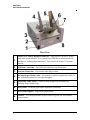
1
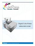
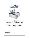
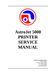
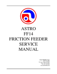
AstroJet M1 COLOR PAGE PRINTER OPERATOR MANUAL ASTRO MACHINE CORP. 630 Lively Blvd. Elk Grove Village, IL 60007 Phone: (847) 364-6363 Fax: (847) 364-9898 www.astromachine.com SAFETY PRECAUTIONS THIS EQUIPMENT PRESENTS NO PROBLEM WHEN USED PROPERLY. HOWEVER, CERTAIN SAFETY RULES SHOULD BE OBSERVED WHEN OPERATING THE ASTROJET M1 PRINTER. BEFORE USING THE PRINTER, YOU SHOULD READ THIS MANUAL CAREFULLY AND FOLLOW THE RECOMMENDED PROCEDURES, SAFETY WARNINGS, AND INSTRUCTIONS: Keep hands, hair, and clothing clear of rollers and other moving parts. Avoid touching moving parts or materials while the machine is in use. Before clearing a jam, be sure machine mechanisms come to a stop. Always turn off the machine before making adjustments, cleaning the machine, or performing any maintenance covered in this manual. The power cord and power supply supplied with the machine should be plugged into a properly grounded, easily accessible wall outlet near the machine. Failure to properly ground the machine can result in severe personal injury and/or fire. The power cord and wall plug is the primary means of disconnecting the machine from the power supply. DO NOT use an adapter plug on the line cord or wall outlet. DO NOT remove the ground pin from the line cord. DO NOT route the power cord over sharp edges or trap it between furniture. Avoid using wall outlets that are controlled by wall switches or shared with other equipment. Make sure there is no strain on the power cord caused by jamming between equipment, walls or furniture. DO NOT remove covers. Covers enclose hazardous parts that should only be accessed by a qualified service representative. Report any cover damage to your service representative. This machine requires periodic maintenance. Contact your authorized service representative for required service schedules. To prevent overheating, do not cover the vent openings. Use this equipment only for its intended purpose. In addition, follow any specific occupational safety and health standards for your workplace or area. This manual is intended solely for the use and information of Astro Machine Corp., its designated agents, customers, and their employees. The information in this guide was obtained from several different sources that are deemed reliable by all industry standards. To the best of our knowledge, that information is accurate in all respects. However, neither Astro Machine Corp. nor any of its agents or employees shall be responsible for any inaccuracies contained herein. AstroJetTM is a registered trademark of Astro Machine Corp. MemjetTM is a registered trademark. All other trademarks are the property of their respective holders. All rights reserved. No part of this book may be reproduced or transmitted in any form or by any means, electronic or mechanical, including photocopying, recording, or any information storage and retrieval system, without permission in writing from the publisher TABLE OF CONTENTS Table of Contents SECTION 1 – Getting Acquainted Front View Rear View Control Panel Button/LED Indicators: SECTION 2 – Installing the Printer Contents of Packaging Choose a Location Unpacking and Setup Hydrating the Printhead Cartridge Remove Service Station Transport Tab Assembling the Printer Connecting the Printer Connecting to the Computer Install the Printer Driver Install the Ink Tanks Install the Printhead Cartridge Installing Envelope Printing Attachment Setting up the Feed SECTION 3 – Operating the AstroJet M1 Setting Up a Job in MS Word Printer Driver Properties General Tab Layout Tab Services Tab SECTION 4 – Maintenance Replacing the Ink Tanks Cleaning/Replacing the Printhead Cartridge Replacing the Service Station Replacing the Ink Waste Tray Replacing the Sheet Separators Jams in the Printer Cleaning Shipping or Transporting the Printer SECTION 5 – Troubleshooting Guide The Memjet The Printer Printhead Appendices Appendix A – AstroJet M1 Specifications Appendix B – Supplies and Optional Hardware Index 1 2 3 5 5 5 5 6 7 7 9 9 10 12 14 17 18 21 21 23 23 24 25 Using the Printer Toolbox TM 1 26 31 31 33 37 40 40 41 42 44 47 47 48 49 49 49 50 i TABLE OF CONTENTS NOTES ______________________________________________________ ______________________________________________________ ______________________________________________________ ______________________________________________________ ______________________________________________________ ______________________________________________________ ______________________________________________________ ______________________________________________________ ______________________________________________________ ______________________________________________________ ______________________________________________________ ______________________________________________________ ______________________________________________________ ______________________________________________________ ii SECTION 1 GETTING ACQUAINTED SECTION 1 – Getting Acquainted Front View 1. Cancel LED Button – Cancels the job being printed. 2. Paper LED Button – Press to stop printing, press to restart printing. Press switch to continue printing. 3. ON/OFF LED Button – Use to turn power ON or OFF during idle time and maintenance. 4. 5. Rear Guide – Holds the media against the Front Plate. Rear Guide Support – Supports the paper/media. 6. Adjustable Media Guide – Adjusts to hold the paper/media against the Envelope/Paper Register Guide. 7. Envelope/Paper Media Guide – All printing is registered against this Guide. It has adjustable positions for envelopes and paper. 8. 9. Top Cover – Provides access to the Print Engine. Front Cover – Provides access to the Ink Tanks. 1 SECTION 1 GETTING ACQUAINTED Rear View 2 1. Main Power Switch, Receptacle and Fuse – Plug in power cord here. Switch turns main power ON/OFF. (Use Control Panel LED Power switch to turn off machine for cleaning and maintenance). Fuse protects the Printer’s electronic circuits. 2. USB Port Connection – The USB cable attaches to the Printer here. 3. Network Connection – The network cable plugs in here. 4. Envelope/Paper Media Guide – All printing is registered against this Guide. It has adjustable positions for envelopes and paper. 5. Adjustable Media Guide – Adjusts to hold the paper/media against the Envelope/Paper Media Guide. 6. Rear Guide – Holds the paper/media against the Front Plate. 7. Rear Guide Support – Supports the paper/media. 8. Counter – LCD displays number of pieces run for a given job. Reset button zeros Counter. SECTION 1 GETTING ACQUAINTED Control Panel Button/LED Indicators The Control Panel has 3 buttons with LED indicators. POWER (ON/OFF) – Turns Printer power ON and OFF. Turn off power for cleaning and maintenance. PAPER (STOP JOB/RESUME – Stops Paper Feed or Resumes Printing. Press to Stop Paper Feed Immediately. Printer will clear media in Printer and stop. Press to Resume Printing. Restart printing after a paper feed error (such as a paper jam or running out of paper). CANCEL (CANCEL JOB – Cancels a Job. Press to Cancel a Job. Once the Printer has stopped, pressing this button clears job from Printer and Print Queue in Driver. NOTE: Cancelled Jobs must be reloaded before printing can resume. PRINTER OPERATION INDICATORS – NORMAL PRINTER STATUS POWER PAPER CANCEL (ON/OFF) (STOP/RESUME) (CANCEL JOB) Power cord plugged in, Main Power Switch ON, Control Panel Power Switch OFF. Unit Powered Up, No Job Loaded. LED OFF N/A – LED OFF N/A – LED OFF LED ON, steady LED OFF Press and hold for 3 seconds to feed single piece at 6 inches/second. N/A – LED OFF Job Loading LED ON, steady LEDs flashing simultaneously ON/OFF once/second. Printing LED ON, steady LEDs flashing alternately ON/OFF once/second. Job Loaded, Printer Stopped. Maintenance Running LED ON, steady LED ON, steady LED ON, flashing ON/OFF LED OFF. once/second. LEDs flashing simultaneously ON/OFF once/second. Wait until Maintenance stops running. 3 SECTION 1 GETTING ACQUAINTED PRINTER ERROR INDICATORS PROBLEM Paper Feed Times Out/Out of Paper POWER (ON/OFF) LED ON, steady PAPER (STOP/RESUME) LED ON, flashing about 3 times/second. CANCEL (CANCEL JOB) LED OFF ACTION: Press PAPER to pause job. Check/clear paper jams or reload Feeder. If OK, press PAPER to resume printing. If not fixed, press CANCEL to cancel the job. Sensor(s) Covered ACTION: LED ON, steady Tilt Error LED ON, steady ACTION: Press PAPER to stop feed. Check that Printer is on a stable, level surface. If OK, press PAPER to resume printing. If not fixed, press CANCEL to cancel the job. Ink Tank Missing ACTION: LED ON, steady Other Errors LED ON, steady ACTION: Press PAPER to stop feed. Try to determine and correct the problem. If OK, press PAPER to resume printing. If not fixed, press CANCEL to cancel the job. LED ON, steady LED OFF Press PAPER to pause job. Remove media covering Sensor or clean Sensor. If OK, press PAPER to resume printing. If not fixed, press CANCEL to cancel the job. LEDs flashing fast alternately ON/OFF about 3 times/second. LED OFF LED ON, steady. Press POWER to turn off Printer. Install missing Ink Tank(s) (see Replacing Ink Tanks in Maintenance) LEDs flashing fast simultaneously ON/OFF about 3 times/second. . MORE TROUBLESHOOTING GUIDES on page 47. 4 SECTION 2 INSTALLING THE PRINTER SECTION 2 – Installing the Printer Contents of Packaging 1. M1 Printer 2. Ink Tanks – Cyan, Magenta, Yellow, Black, Black 3. Printhead Cartridge 4. Media Side Guides: Registration (Fixed) and Adjustable – mounting screws attached to Printer 5. Rear Media Support Guide – thumbscrew attached to Printer 6. Media Support Wedges: Narrow and Wide – mounting hardware attached to Rear Media Support Guide 7. Envelope Printing Attachment (Use when printing large volume envelope jobs) 8. AC Power Cord 9. USB Cable 10. Operator Manual 11. Driver Software CD Before using the AstroJet M1 Printer the following must be done: Choose a location for the Printer Unpack and assemble the Printer Hydrate the Printhead Cartridge Remove the Service Station Transport Tab Plug in the Printer and connect it to the computer Install the Printer Driver Install the Ink Tanks Install the Printhead Set up the feed on the Printer Choose a Location The AstroJet M1 should be placed on a sturdy level worktable or cabinet at least 9 inches from any walls. Protect the Printer from excessive heat, dust, and moisture. Avoid placing it in direct sunlight. Unpacking and Setup Remove the Printer and its parts from the carton. Remove all packing tape. The screws that attach the various parts of the guides to the Printer are under the tape in their respective positions. 5 SECTION 2 INSTALLING THE PRINTER Hydrating the Printhead Cartridge Before you begin assembling the Printer, it is a good idea to hydrate the Printhead Cartridge. CAUTION Hold the Printhead Cartridge by the handles ONLY. DO NOT touch the ink couplings, nozzle surface or electrical contacts. DO NOT unpack the Printhead Cartridge until the Printer is ready for installation. Once unwrapped, delay in installing the Printhead can compromise print quality due to dehydration. DO NOT place an unwrapped Printhead on any surface before installing. Protect the Printhead from dust, fibers, dirt and other contaminants at all times. 6 1. Carefully remove the Printhead Cartridge from the foil packaging. [A] Tear at notch or cut end with scissors. [B] Remove the protective plastic cover. Hold the Printhead by the handle and unclip the cover from the Printhead. [C] Remove protective strip from the Printhead Electrical Contacts. DO NOT allow removed strip to touch the electrical contacts. [D] Remove protective strip from the Printhead Nozzles. Hold the Printhead by the handle with one hand. Pull the strip tab with the other hand and slowly peel the strip from the Printhead. DO NOT pull the strip at any angle less than 45° with the Printhead surface. DO NOT allow removed strip to touch the Printhead Nozzles. 2. Pour distilled water into the orange plastic cover you removed in Step 1B and carefully reinstall the Printhead back into the plastic cover. Set the Printhead aside for installation later. This rehydrates Printhead and allows easier priming once it is installed in the Printer. SECTION 2 INSTALLING THE PRINTER Remove Service Station Transport Tab 1. Open the Top Cover. 2. Release the two latches (one on either side of the Print Engine). Open the top half of the Print Engine by lifting both levers at the same time. 3. Pull up on the two tabs to remove the cardboard Transport Tab up from the Service Station. 4. Carefully close and relatch the Upper Print Engine. Then close the Top Cover. Assembling the Printer Begin by installing the Adjustable Side Guide with two screws [1]: 7 SECTION 2 INSTALLING THE PRINTER Next install the Envelope/Paper Side Guide using the two screws [2] provided. Attach the Rear Paper Support using the knob [3] provided. NOTE: The two outside holes fit over the socket head screws. Install the Rear Guide using the thumbscrew and washer [4] provided. The washer goes between the screw and the Rear Paper Support. 8 SECTION 2 INSTALLING THE PRINTER Connecting the Printer Plugging in the Printer Connect the power cord to the receptacle [1] at the rear of the Printer. The internal power supply in the Printer is rated 115 to 240VAC, 50/60 Hz. CAUTION DO NOT USE AN ADAPTER PLUG OR EXTENSION CORD TO CONNECT THE PRINTER TO THE WALL RECEPTACLE. DO NOT USE OUTLETS CONTROLLED BY WALL SWITCHES. DO NOT USE AN OUTLET THAT SHARES THE SAME CIRCUIT WITH LARGE ELECTRICAL MACHINES OR APPLIANCES. Connecting to the Computer The Printer connects to the computer through the USB Port [2]. A Network Port [3] is provided when operating in a network environment. See “Network Connection Setup” in the “Using the M Series Toolbox” section. Turning Power ON and OFF Powering Up Printer: 1. Press the Main Power Switch on the Rear Panel. 2. Press the Power Button on the Control Panel. Powering Down Printer: CAUTION WHENEVER POWERING DOWN UNIT, ALWAYS: 1. PRESS THE POWER BUTTON ON THE CONTROL PANEL. 2. WAIT FOR THE PRINTER TO STOP PROCESSING. 3. THEN PRESS THE MAIN POWER SWITCH ON THE REAR PANEL. 9 SECTION 2 INSTALLING THE PRINTER Install the Printer Driver For the Printer software to operate properly check that the computer system meets these minimum requirements: Windows XP, Windows Vista, Windows 7. (Supports 32 and 64 bit systems) You must have administrative privileges on the system. Microsoft Internet Explorer 6.0 or higher. Java version 6 or higher USB 2.0 port (ports will be identified as “USB2” or “Enhanced” in the Device Manager.) Microsoft .NET Framework 3.5 installed (Even if you have a higher version installed, version 3.5 must also be installed. IMPORTANT: Before installing the Printer software (Toolbox and Driver), you should temporarily disable all antivirus programs and firewalls. In addition, you must be logged onto the system with full administrative privileges (admin rights). NOTE: If installing over USB, do not plug in the USB cable until prompted. 10 1. Make sure the Printer is plugged in and turned OFF. Disconnect the USB connection if you have plugged it in already. Install the disk supplied with the Printer in your CD drive. When the AutoPlay Window opens, click “Run Setup.exe” to start. 2. The “Install Printer Software” window opens on the computer screen. Make sure the computer system meets the minimum requirements and you have followed the other instructions on the screen. Click “Install Printer Software”. 3. The License Agreement window opens. Carefully read the “End User Agreement”. If you agree to the terms, check “I accept…” then click Next>. SECTION 2 INSTALLING THE PRINTER 4. After a few moments the “Printer Connections” window opens. Click “Configure to print using USB”. Then click Next>. 5. After a few moments the “M Series Driver” window opens followed by the “Would you like to install this device software?” window. Click Install and the driver software will load from the disk. 6. The software will start to download and a second “Would You Like to Install This Device Software” opens. Click Install. 7. The “Connect Device Now” window opens. Switch the Printer on and connect the USB cable. Don’t click on either button. The software will then finish installing. 11 SECTION 2 INSTALLING THE PRINTER 8. The “Finished software installation” window opens. Do not print a test page since printer is not set up yet. Do not check the Print Test Page. Click Next>. 9. The M Series Driver welcome window returns. Note that you can click on the User’s Guide for installation, document set up and printer maintenance, cleaning and troubleshooting information. If connected to the Internet you can click Website. Click Exit to close the CD. 10. Restart the computer to complete the installation. Install the Ink Tanks M Series Printers use a single Printhead Cartridge and five Ink Tanks (two Black, one Cyan, one Magenta, and one Yellow). Install the Ink Tanks as follows: 1. 12 Open the Printer Toolbox. Go to All Programs, open the Astro Machine Folder and open the Toolbox. On the Opening Screen you will see System Status information in the upper left corner. SECTION 2 INSTALLING THE PRINTER 2. Open the Front Cover (hinged at bottom). Open the three Latches [A]. 3. Remove the new Tank(s) from packaging. 4. Slide the new Tanks (label up) into their appropriate color slots [B]. INSTALLATION TIP – Make sure the Tanks seat properly. Insert the Tank into the appropriate Ink Station, then pull the Tank back about an inch and push forward firmly to insure that the Ink Nozzles penetrate the seals on the Tanks. 5. Turn the Printer ON by pressing the Main Power Switch on the Rear Panel, then pressing Control Panel Power Button. Watch the Toolbox screen on your computer; you will see the ink colors fill in as the Tanks are installed. If the ink color does not fill in after a few seconds, reinstall the Tank. 6. Close the three Latches. Close the Front Cover. WARNING The ink in the Ink Tanks may be harmful if swallowed. Keep new and used Tanks out of reach of children. Discard empty tanks immediately. 13 SECTION 2 INSTALLING THE PRINTER Install the Printhead Cartridge The Printhead Cartridge is a delicate precision device. Handle with extreme care to avoid damage and issues that could degrade print quality. CAUTION Hold the Printhead Cartridge by the handles ONLY. DO NOT touch the ink couplings, nozzle surface or electrical contacts. DO NOT unpack the Printhead Cartridge until the Printer is ready for installation. Once unwrapped, delay in installing the Printhead can compromise print quality due to dehydration. DO NOT place an unwrapped Printhead on any surface before installing. Protect the Printhead from dust, fibers, dirt and other contaminants at all times. 1. With the Printer power ON, open the Top Cover. Press the Printhead Cover Release Button [1]. The Printer will run a routine, then the Cover will pop open [2]. NOTE: Remove the Cap Protectors on the Ink Nozzles [3]. Be sure to open the Cover fully to retract the Ink Nozzles. CAUTION DO NOT PRY OR MANUALLY LIFT THE PRINTHEAD COVER OR THE COVER MAY BREAK. ONLY OPEN THE COVER USING THE RELEASE BUTTONS ON THE PRINTER OR THE PRINTHEAD RELEASE COMMANDS IN THE SERVICES TAB OR M SERIES TOOLBOX. 14 SECTION 2 INSTALLING THE PRINTER 2. Take the Printhead Cartridge you hydrated and set aside earlier, remove the orange cover and proceed to Step 5. Otherwise, follow the Steps below: Carefully remove the Printhead Cartridge from the foil packaging. [A] Tear at notch or cut end with scissors. [B] Remove the protective plastic cover. Hold the Printhead by the handle and unclip the cover from the Printhead. [C] Remove protective strip from the Printhead Electrical Contacts. DO NOT allow removed strip to touch the electrical contacts. [D] Remove protective strip from the Printhead Nozzles. Hold the Printhead by the handle with one hand. Pull the strip tab with the other hand and slowly peel the strip from the Printhead. DO NOT pull the strip at any angle less than 45° with the Printhead surface. DO NOT allow removed strip to touch the Printhead Nozzles. IMPORTANT! Pour distilled water into the orange plastic cover you removed in Step 4B and carefully reinstall the Printhead back into the plastic cover. Set the Printhead aside for 15 to 20 minutes. This rehydrates Printhead and allows easier priming once it is installed in the Printer. WARNING To avoid electrical shock or shorting: Before installing the Printhead, make sure the nozzles are hydrated and the contacts are DRY! 3. Carefully insert the Cartridge into the compartment at an angle [4], with the Printhead surface facing down and the Ink Nozzles facing the Ink Hoses. Once it is seated, gently tilt the Cartridge back until it snaps into an upright position [5]. DO NOT FORCE the Cartridge into position. 15 SECTION 2 INSTALLING THE PRINTER 4. Wet the Printhead Surface. This ensures that the Printhead will prime correctly. Open the Top Cover. Release and lift up the two latches (one on each side of the Printhead Assembly) at the same time to raise the Printhead Assembly. Moisten the Printhead nozzles using distilled water and a wet, lint-free cloth. Close and relatch the Printhead Assembly. CAUTION OPERATE AND HOLD ONTO BOTH LATCHES WHEN OPENING AND CLOSING THE PRINTHEAD ASSEMBLY TO PREVENT DAMAGE. DO NOT ALLOW THE ASSEMBLY DROP BY ITSELF TO CLOSE LATCHES. TO PREVENT DAMAGE TO THE INK LINES, A STOP LIMITS RAISING THE ASSEMBLY MORE THAN 60°. 5. Close the Printhead Cover [6]. The Printer will run a start-up routine and prime ink into the Printhead. This may take a few minutes. Make sure that ink is flowing through the hoses. 6. Watch the Toolbox screen on your computer again. Notice that some of the information is in red. As the Printer circulates ink and primes the system these fields should all turn black. 7. When the Printer stops processing and all the fields in System Status are black, the Printer is ready for use. Close the Top Cover. NOTE: The Printer may take up to 12 minutes to set itself up during initial startup. This is normal. The machine will emit a number of chirps, whirrs and other noises as it circulates ink and runs systems. 16 SECTION 2 INSTALLING THE PRINTER Installing Envelope Printing Attachment Use this attachment if you are primarily printing envelopes or running large batches of envelopes. The attachment flattens the envelope flap for better print consistency. 1. Open the Top Cover. Press the Printhead Latch Cover Release Button (or click the Printhead Release from the Services Tab or the User Interface screen in the Toolbox.) The Printer pumps any ink in the system back into the Tanks. Wait for the Printhead Latch Cover to open. 2. Make sure the Printhead Latch Cover is fully opened to retract the ink lines. Tilt the Printhead Cartridge back toward the ink lines and lift it up slightly. This will keep the printing surface out of the way during installation. 3. Open the Printhead Clamshell. 4. [A] Slide the Envelope Printing Attachment up behind the metal support. [B] Push the Attachment to the right side of the Printer to lock the Attachment in place. [C] While the Printhead Clamshell is still open, snap the Printhead Cartridge back into place. Make sure the Attachment is aligned with the Printhead Cartridge as shown. 5. Close and relatch the Printhead Clamshell. Close the Printhead Latch Cover and Top Cover. Reprime the system. NOTE: Remove the Attachment if you are going to primarily run flat sheets. 17 SECTION 2 INSTALLING THE PRINTER Setting up the Feed The AstroJet M1 Printer is equipped with four Sheet Separators, two Side Guides and a Rear Media Guide. The Sheet Separators are adjusted individually as follows: 18 1. Move the Left-hand Side Guide into position. This Guide has two positions. The position closest to the Side Frame is for 9.5" media and the position closest to the center of the Printer is for printing 8.5" wide media edge to edge. 2. Loosen the locking screws located behind the Sheet Separators and raise the Separators, then tighten the locking screws to hold the Separators in the “Up” position. 3. Place a single piece of the media to be run under the Separators. Always place the media against the Left-hand Paper Guide. Loosen the Separator locking screw and allow the Separator to settle onto the media. Then tighten the locking screw. Repeat for each Separator. SECTION 2 INSTALLING THE PRINTER 4. Adjust the Right-hand Side Guide so that it is about 1/32-inch from the sides of the media. Tighten the locking knob on the Side Guide. Place a stack of media in the machine. Press and hold the Paper key to feed one piece through the Separator. NOTE: To prevent misfeeds and tearing, keep the Right-hand Side Guide at least 1/8" from the Side Frame. 5. Adjust the Rear Guide Support by using the knob to slide the Guide right and left. If you experience feeding problems, slide the Rear Support Guide right or left keep the media aligned with the Media Guides. 6. Adjust the Rear Media Guide by loosening the locking screw and moving the Guide to raise the media approximately 2" above the Feed Table for paper and about 1/2" for envelopes. NOTE: The amount of media that can be stacked on the Printer is determined by the weight of the material. The Feeder may not feed larger and heavier media when the stack is full. If this is the case, reduce the amount of media in the stack until the Feeder functions properly. 19 SECTION 2 INSTALLING THE PRINTER NOTES ______________________________________________________ ______________________________________________________ ______________________________________________________ ______________________________________________________ ______________________________________________________ ______________________________________________________ ______________________________________________________ ______________________________________________________ ______________________________________________________ ______________________________________________________ ______________________________________________________ ______________________________________________________ ______________________________________________________ 20 SECTION 3 OPERATING THE ASTROJET M1 SECTION 3 – Operating the AstroJet M1 Once the Printer Driver is installed on your computer and the Printhead is primed, you are ready to start printing. Set up your job and send it to the Printer. The Printer will start and print. This rest of this section is divided into two parts: 1. How to set up a job to print from Microsoft Word. 2. Driver properties and the various options available when you run a job. The Printer Driver that you installed on your computer in Section 2 should be set as the default driver. It will then be accessible through your applications such as Microsoft Word. Other types of applications and database management software will work in a similar manner when using this Driver. This Section further assumes that you have set up the feed and the Printer is connected to your computer. Setting Up a Job in MS Word When setting up a job to print in MS Word or any other application, first determine the print area of the Printer and the paper sizes it can handle. Maximum print area for the Printer: 8.5" wide x 17" long. Maximum paper size Printer can feed: 9.5" wide x 17" long. (See diagram at right.) Minimum paper size Printer can feed: 3" wide x 4.2" long. To set up the maximum print area for a 9.5" x 17" document, set the paper size to 9.5" wide by 17" long in the Custom Paper setting. Set top and bottom margins to 0" or any margin you require. Set right-hand and left hand margins to 0.5". You can now layout the job and print the maximum printing area. For other page sizes such as 8.5" x 11" (standard letter) or 8.5" x 14" (legal size) set the paper size to the exact size and set the margins as needed. NOTE: Set the Left-hand Side Guide to the proper 9.5" position when running 9.5" wide media. Set the Guide to the 8.5" position when running 8.5" or narrower media. Envelopes: Select an envelope (example uses a #10 envelope) from Page Setup in MS Word. Feed the envelope by the 9.5" inch width, the fastest way to run envelopes especially if you are addressing them with a Mail Merge. Set the top and bottom margins to 0", the left and right margins at 0.5" as shown. 21 SECTION 3 OPERATING THE ASTROJET M1 Printing a Typical Job on 8.5-inch by 5.5-inch Paper The AstroJet M1 can print edge-to-edge on an 8.5" x 5.5" document. Follow these steps to set up a job: 1. Go to File, then Page Setup and select 0" margins. 2. Select the Paper tab, select Paper Size “Custom size” then set the paper Width to 8.5" and the paper Height to 5.5". Then click OK. 3. The screen at right is an example of a job to be printed. Once the job is ready for printing, select Print from the File menu and print the job. For more information about changes that can be made in the Driver please see the Printer Driver section. 22 SECTION 3 OPERATING THE ASTROJET M1 Printer Driver Properties The Printer Driver for the AstroJet M1 works the same as any other Printer Driver for Windows. It does have some enhancements to help you maximize the ability of the Printer to print variable addressed pieces quickly and efficiently. Windows XP, Vista: Once the job is set up, click File, then Print. The window on the right will open. Make sure the M Series Driver is the selected Printer. Clicking on Properties opens the “Properties” window. Windows 7: Once the job is set up, click Print. Make sure the M Series Driver is the selected Printer. The window at right will open. Clicking on Properties opens the “Properties” window. General Tab The General tab lets you select: Orientation – Portrait (Default), Landscape, Rotate 180° and Mirrored. Page Buffering – Allows the entire print job to load before printing starts. Copies – Lets you choose the number of copies to be printed. NOTE: Print Last Page First is set as the default. This means the job starts printing from the last page. The entire job will load into the Printer before printing starts. Large jobs may take some time to load. Unchecking the box prints the job starting with the first page. Printing starts as soon as first page loads. Media – Allows you to choose a different size paper than the document was originally designed for. The document is automatically resized to fit the new media. 21 sizes are available. You can also create and save a Custom Size to suit your needs. NOTE: Do not exceed maximum paper size for the Printer. Print Quality – Select Normal or Best. Normal is 1600 x 800 dpi, checking the Half Speed box slows printing for higher quality on glossy stock. Best setting is 1600 x 1600 dpi, for use when high quality images are required. My Print Settings – Access your custom print settings for various jobs that you uploaded through the “Media Profile Upload” in the Toolbox. 23 SECTION 3 OPERATING THE ASTROJET M1 Layout Tab Layout allows you change how the document prints without changing the original document. 24 Resizing – Lets you specify the Original Size or Custom Resize: lets you resize the original as a % of normal size. The Printer will print the document in the size you selected regardless of the size of the paper selected. Print on: lets you specify the particular size of paper that you want to print on regardless of the size of the original document. Checking “Scale to Fit” automatically resizes the document to fit on the new page size. Printing Adjustments – Allows you to make minor positioning changes to the print area in relation to the media if needed. NOTE: Only works on jobs using less than the full print area (less than 8.5" wide). Watermark – Prints a light background watermark in the paper while printing the original document. When this option is selected the “First page only” option prints the watermark on the first page, but not subsequent pages, unchecking prints the watermark on all pages. The Custom button lets you create a new watermark or edit an existing watermark, including font selection, color, size and printing angle. My Print Settings – Access your custom print settings for various jobs that you uploaded through the “Media Profile Upload” in the Toolbox. SECTION 3 OPERATING THE ASTROJET M1 Services Tab Services allows you to: Print Configuration Page – Prints out the current configuration of the Printer including current Firmware Version, Network Connection, printer Serial Number and more. Print Sample Page – Prints type and color bands to check print quality. Print Diagnostic Page – Shows basic Printer information, memory, Network Settings, Event Log and RAM partitions. Release the Printhead – Performs the same task as the Cover Release button on the Printer. Deprimes the ink from the system and opens the Printhead Cover for removing/installing the Printhead Cartridge. System Deprime – Drains the ink in the lines back into the Ink Tanks before servicing the Printhead Cartridge or prepping the Printer for storage or transport. Circulate Ink – Purges air from the ink lines and primes the system after replacing the Printhead Cartridge and/or the Ink Tanks. User Maintenance, Levels 1 to 3 Level 1 – Circulates ink, wipes and cleans the Printhead Cartridge. Level 2 – Runs cleaning and wiping routine twice for better flushing and cleaning. Level 3 – Runs the cleaning routine multiple times for the most thorough flushing and cleaning of the printhead. NOTE: If the Printer is connected to a network and the Driver buttons fail to activate the cleaning process, you can perform the same functions from the Toolbox User Interface. If you are connected to the Internet you can also order supplies and get help with Printer questions. 25 SECTION 3 OPERATING THE ASTROJET M1 Using the Printer Toolbox Once the Printer Driver is installed you have access to the Printer Toolbox. The Toolbox lets you monitor ink usage, perform diagnostic checks, print reports and run maintenance tasks on the Printer from your computer. To open the Toolbox: Click Start from the Windows taskbar, go to All Programs, open the Astro Machine folder, then click on “Toolbox”. When the “User Interface” window opens you will find a series of Menu Options you can click on at the lower left of the screen. You can check the Printer Status in the upper left part of the screen. User Interface [A] Screen Buttons: Let you perform maintenance and operating tasks. You can use the screen buttons to Clear Errors, Cancel a Job, Reset the Job Counter, and Reset the Page Counter. You can also: Wipe Printhead – Activates the Service Station to wipe the Printhead. Release the Printhead – Performs the same task as the Cover Release button on the Printer. Pumps the ink back into the Ink Tanks and opens the Printhead Cover to remove/install the Printhead Cartridge. Circulate Ink – Purges air from the lines and primes the system after replacing the Ink Tanks or Printhead Cartridge. System Deprime – Pumps the ink back into the Ink Tanks prior to replacing the Printhead Cartridge or transporting the Printer. 26 SECTION 3 OPERATING THE ASTROJET M1 Cleaning Buttons: Provide 3 levels of cleaning for the Printhead Cartridge. These work the same way as the 3 Maintenance Level Buttons in the Printer Driver: Quick Clean Printhead – Circulates ink, wipes and cleans the Printhead Cartridge. Normal Clean Printhead – Runs cleaning and wiping routine twice for better flushing and cleaning. Full Clean Printhead – Runs the cleaning routine multiple times for the most thorough flushing and cleaning of the Printhead. Eject Service Station – Releases the Service Station for removal for cleaning, repair or replacement. Install Service Station – Pulls the Service Station back into place after cleaning, repair or replacement. Shutdown the Printer – Turns the Printer OFF from your computer. [B] Basic Printer Settings – Lets you adjust automated service and cleaning intervals, adjust the feeder speed for a job, determine ink usage for a job prior to printing and adjust the Printer for pre-printed media. KWS Setting – (Keep Web Spitting) Keeps Printhead hydrated while running a job. Select from 4 settings to determine how much ink will “spit” from the Printhead Nozzles. Set in conjunction with “Mid Job Servicing” which determines the frequency of the Printer stopping for self-servicing during a job. Mid Job Servicing – Sets the frequency of automatic maintenance cycles run during a job. NOTE: Changing the setting from “Default” may cause print quality issues and reduce Printhead life. Cutsheet Feeding Mode – Permits you to change how the Printer feeds media depending on the type of job you are running: Safe Feed – Leaves a larger gap between pieces to reduce overprinting onto the next piece. This setting is useful for more intricate printing jobs or jobs requiring the best print quality. Max_Throughput – Allows fastest printing speed. The Printer works like a stream feeder. This setting is useful for simple printing jobs. NOTE: These two settings can be changed “on the fly” without stopping the job. Example: While running a job in “Max-Throughput” you find that the media is jamming excessively due to speed. Open the Toolbox, check “Safe Feed” and click “Submit”. The Printer will automatically adjust without having to pause or stop the job. Ignore Exit Sensor – Checking this box turns the Exit Sensor OFF. The Sensor may not “see” the trailing edge of a piece of pre-printed media if the back of that media is dark or black. (Example: adding addresses to a pre-printed postcard.) This may “fool” the Sensor into thinking a jam has occurred. Turning the Sensor OFF prevents these “false jams” from stopping the job. 27 SECTION 3 OPERATING THE ASTROJET M1 [C] Firmware Download – Get the latest version of firmware for your Printer. How to download new firmware: 1. 2. 3. 4. 5. When you are notified that new firmware is available for your Printer, download the *.fbf file and save it to your desktop. Open the Toolbox. On the “User Interface” page, find Firmware Downloads. Click the “Browse” button and find the file you just saved to your desktop. Click “Submit”. DO NOT touch the Printer until the firmware is loaded! A message will appear on your screen warning you not to unplug or shut off the Printer. Once the firmware finishes loading (about 5-10 minutes), the Control Panel lights and Printer shuts OFF. Press the Control Panel Power button to restart the Printer and installation is complete. Diagnostics From this screen you can see the current status of your Printer. You can also: Print Sample Page – Prints type and color bands to check print quality. Print Configuration Page – Shows the current configuration of the Printer including Firmware Version, Network Connection, Printer Serial Number and more. Print Diagnostic Page – Shows basic Printer information, memory, Network Settings, Event Log and RAM partitions. Print Demo Page – Prints a 4-color sheet. Print Color Bars Page – Shows how well Printhead is printing. Ink Usage Allows you to monitor the estimated amount of ink left in each of the five Ink Tanks. You can monitor ink consumption and schedule Tank changes (saving down-time during a print run.) NOTE: Ink Usage only works when you start with a new Ink Tank and leave it in the Printer. Ink Estimation Mode – Checking this box lets you predetermine how much ink a given job may use prior to printing. This can be useful for determining per piece costs. The job is sent to the Printer and loads, but does not print. Once the job is loaded, the chart shows the amount of ink (by color) that the job will use. NOTE: The estimating process will take as long as the job would take to print (i.e., if the job would take 1 hour to print, the estimate will take 1 hour to display.) 28 SECTION 3 OPERATING THE ASTROJET M1 Network Configuration Permits you to view, enter or change settings to connect the Printer to your network. Network Connection Set Up: 1. The Printer is still connected to the computer via the USB cable. To connect the Printer to a network, open the Toolbox. On the “User Interface” page, click Network Config. 2. The “Network Status and Configuration” page opens. Your IT person can choose the Network Settings box to enter the correct settings for your network. 3. Connect Ethernet cable to Network Port on Rear Panel of Printer. 29 SECTION 3 OPERATING THE ASTROJET M1 Service Menu For authorized personnel only. Provides access to more advanced Printer control and maintenance menus. 30 SECTION 4 MAINTENANCE SECTION 4 – Maintenance This section covers how to care for the Ink Tanks, Printhead Cartridge, Service Station, clear paper jams and replace the Sheet Separators. Replacing the Ink Tanks Replace the Ink Tanks when the ink runs out. 1. Open the Printer Toolbox. Go to All Programs, open the Astro Machine Folder and open the Toolbox. On the Opening Screen you will see System Status information in the upper left corner. 2. Turn the Printer OFF with the Control Panel Power Button and open the Front Cover (hinged at bottom). Open the three Latches [A] and pull the Ink Tank(s) out of the Printer. 3. Remove the new Tank(s) from packaging. 4. Slide the new Tank (label up) into its appropriate color slot [B]. INSTALLATION TIP: Make sure the Tanks seat properly. Insert the Tank into the appropriate Ink Station, then pull the Tank back about an inch and push forward firmly to insure that the Ink Nozzles penetrate the seals on the Ink Tanks. 31 SECTION 4 MAINTENANCE 5. Turn Printer ON with Control Panel Power button. Watch the Toolbox screen on your computer; you will see the ink colors fill in as the Ink Tanks are installed. If the ink color does not fill in after a few seconds, reinstall the Ink Tank. 6. Prime the system by running the Circulate Ink routine from the User Interface window in the Toolbox. 7. Watch the Toolbox screen on your computer again. Notice that some of the information is in red. As the Printer circulates ink and primes the system these fields should all turn black. 8. When the Printer stops processing and all the fields in System Status are black, the Printer is ready for use. 9. Latch the three Latches. Close the Front Cover. WARNING The ink in the Ink Tanks may be harmful if swallowed. Keep new and used Ink Tanks out of reach of children. Discard empty Ink Tanks immediately. Storage New Ink Tanks should be stored in their original packaging and kept away from heat. Opened Ink Tanks should remain in the Printer. Disposal The Ink Tank may be disposed of in a normal manner. Clean up spills with soap and water. Abrasive soap is effective in cleaning ink off your hands. 32 SECTION 4 MAINTENANCE Cleaning/Replacing the Printhead Cartridge Cleaning The Printhead in the AstroJet M1 Printer is cleaned automatically each time the machine is turned on or when the Level 1 Maintenance routine is performed by the operator. This can be found under the Service Tab, Level 1 Maintenance in the Printer Driver. Level 2 and Level 3 Maintenance can be used to more thoroughly clean or clear the Printhead. If running the Maintenance Levels doesn’t help improve print quality, the Printhead Cartridge can be cleaned manually. Open the Top Cover. Release and lift up the two latches (one on each side of the Printhead Assembly) at the same time to raise the Printhead Assembly. Moisten the Printhead nozzles using distilled water or deionized water (reference ASTM D5127-90 Type E-II Electronic Grade Water) with a wet, lint-free cloth. Take care not to damage the copper contacts, the metal plate, or the gold Printhead surface. Close and relatch the Printhead Assembly. Generally, when the ink supply is adequate and the print quality remains poor, or when the built-in cleaning processes or manually cleaning the Printhead has not helped the image quality, the Printhead should be replaced. CAUTION Hold the Printhead Cartridge by the handles ONLY. DO NOT touch the ink couplings, nozzle surface or electrical contacts. DO NOT unpack the Printhead Cartridge until the Printer is ready for installation. Once unwrapped, delay in installing the Printhead can compromise print quality due to dehydration. DO NOT place an unwrapped Printhead on any surface before installing. Protect the Printhead from dust, fibers, dirt and other contaminants at all times. Replacing the Printhead Cartridge 1. Open the M Series Toolbox. Go to All Programs, open the Astro Machine Folder and open the Toolbox. On the Opening Screen you will see information about the System Status in the upper left corner. 33 SECTION 4 MAINTENANCE 2. Open the Top Cover. Press the Printhead Cover Release button [1]. The Printer pumps any ink in the system back into the Tanks. Then the Printhead Cover pops open [2]. NOTE: You can perform this same function from your computer by clicking Printhead Release from the Services tab in Print Properties or the User Interface screen in the M Series Toolbox. CAUTION DO NOT PRY OR MANUALLY LIFT THE PRINTHEAD COVER OR THE COVER MAY BREAK. ONLY OPEN THE COVER USING THE RELEASE BUTTONS ON THE PRINTER OR THE PRINTHEAD RELEASE COMMANDS IN THE SERVICES TAB OR M SERIES TOOLBOX. 3. Make sure the Printhead Cover is fully opened to retract the ink lines. Remove the used Printhead Cartridge by tilting it toward the ink lines [3], then carefully lifting it out of the Printhead Compartment. 4. Carefully remove the Printhead Cartridge from the foil packaging. [A] Tear at notch or cut end with scissors. [B] Remove the protective plastic cover. Hold the Printhead by the handle and unclip the cover from the Printhead. [C] Remove protective strip from the Printhead electrical contacts. DO NOT allow removed strip to touch the electrical contacts. [D] Remove protective strip from the Printhead Nozzles. Hold the Printhead by the handle with one hand. Pull the strip tab with the other hand and slowly peel the strip from the Printhead. DO NOT pull the strip at any angle less than 45° with the Printhead surface. DO NOT allow removed strip to touch the Printhead Nozzles. NOTE: Keep foil packaging to store/dispose of old Printhead Cartridge. IMPORTANT! Pour distilled water into the orange plastic cover you removed in Step 4B and carefully reinstall the Printhead back into the plastic cover. Set the Printhead aside for 15 to 20 minutes. This rehydrates Printhead and allows easier priming once it is installed in the Printer. 34 SECTION 4 MAINTENANCE WARNING To avoid electrical shock or shorting: Before installing the Printhead, make sure the nozzles are hydrated and the contacts are DRY! 5. Carefully insert the Cartridge into the compartment at an angle [4], with the Printhead surface facing down and the Ink Nozzles facing the Ink Hoses. Once it is seated, gently tilt the Cartridge back until it snaps into an upright position [5]. DO NOT FORCE the Cartridge into position. 6. Wet the Printhead Surface. This ensures that the Printhead will prime correctly. Open the Top Cover. Release and lift up the two latches (one on each side of the Printhead Assembly) at the same time to raise the Printhead Assembly. Moisten the Printhead nozzles using distilled water and a wet, lint-free cloth. Close and relatch the Printhead Assembly. CAUTION OPERATE AND HOLD ONTO BOTH LATCHES WHEN OPENING AND CLOSING THE PRINTHEAD ASSEMBLY TO PREVENT DAMAGE. DO NOT ALLOW THE ASSEMBLY DROP BY ITSELF TO CLOSE LATCHES. TO PREVENT DAMAGE TO THE INK LINES, A STOP LIMITS RAISING THE ASSEMBLY MORE THAN 60°. 35 SECTION 4 MAINTENANCE 7. Close the Printhead Cover [6]. The Printer will automatically run a start-up routine and prime the ink into the Printhead. This may take a few minutes. Make sure that ink is flowing through the hoses. If air bubbles appear you may have to tap the lines or run the Circulate Ink routine to clear them. 8. Watch the Toolbox screen on your computer again. Notice that some of the information is in red. As the Printer circulates ink and primes the system these fields should all turn black. 9. When the Printer stops processing and all the fields in System Status are black, the Printer is ready for use. Close the top cover. IMPORTANT CHECK INK TANKS. PRINTER MAY NOT FULLY REPRIME IF TANKS ARE LESS THAN 1/3 FULL. NOTE: The Printer may take up to 12 minutes to set itself up during initial startup. This is normal. The machine will emit a number of chirps, whirrs and other noises as it circulates ink and runs systems. 36 SECTION 4 MAINTENANCE Replacing the Service Station The Service Station is designed provide a long service life. However, should it need to be replaced, follow these steps. The Service Station is located above the Ink Tank Station. TURN PRINTER POWER OFF. CAUTION WHENEVER POWERING DOWN UNIT, ALWAYS: 1. PRESS THE POWER BUTTON ON THE CONTROL PANEL. 2. WAIT FOR THE PRINTER TO STOP PROCESSING. 3. THEN PRESS THE MAIN POWER SWITCH ON THE REAR PANEL. 1. Open the Front Cover (hinged at bottom). Remove the Exit Roller Cover by removing the four (4) screws. Open the Top Cover. 2. Slide the Service Station out of the Service Station port. NOTE: Do not pull Station all the way out until you disconnect the Ribbon Cable. 37 SECTION 4 MAINTENANCE 3. Disconnect the Ribbon Cable. Slide the Latch open on the Service Station Circuit Board to release the Ribbon Cable. Remove the Service Station. 4. Carefully unwrap the new Service Station. NOTE: Loose parts may fall out. Keep roller side facing up when removing packaging. CAUTION Make sure latches on the Wiper Roller are fully latched before installing the Service Station. 5. 38 Slide the Latch open on the Service Station Circuit Board. SECTION 4 MAINTENANCE 6. [1] Plug the Ribbon Connector (blue side up) into the space under the Latch. [2] Close the Latch. 7. [1] Slide the Service Station into the Service Station port until it touches the bar. [2] Look down through the Top Cover to make sure Service Station is aligned with the bar. IMPORTANT! Service Station must be perfectly aligned with bar to prevent misalignment and operating problems. 8. GENTLY push the Service Station while turning the large Gear on right side of Print Engine clockwise. Gear should engage gear on Service Station Roller and pull it in. Once the Service Station starts moving, stop turning the gear. Powering up the unit will pull the Service Station the rest of the way in. NOTE: Make sure the wick hanging below the Service Station is inside the plastic trough inside the Ink Tank Station to prevent ink seepage. 9. Replace the Exit Roller Door and Close the Front Cover. 39 SECTION 4 MAINTENANCE Replacing the Ink Waste Tray The Ink Waste Tray soaks up any excess ink that may drip from the Print Engine during operation. After a period of time it may become saturated and need replacement. 1. Open Ink Tank Door. 2. Push in on the Tabs to release the Ink Waste Tray and remove it from unit. 3. Replace with a new Ink Waste Tray. Replacing the Sheet Separators The Sheet Separators insure separation of the pieces as they are being fed. If you experience double sheet feeding and cannot adjust the Separators to prevent it, replace the Separators. Replacing the Sheet Separators is not difficult: 1. Turn the Printer OFF and unplug it and from the power source. 2. Release the Separator by loosening the Locking Knob and moving the Paper Side Guides to their maximum opened position. 3. Lower the Separators so that they touch the Feed Roller. 4. Remove the screw [A] and the Separator Cover [B]. Then remove the Separator [C] by prying it out of the Holder. 5. Install a new Separator and replace the Separator Support and screw. 40 SECTION 4 MAINTENANCE Jams in the Printer If a jam occurs, STOP the Printer. Some possible causes for jamming are: 1. 2. 3. 4. Feeding more than one piece of media (double-feeding). Damaged media, such as dog-eared (turned down corners). Media that is not stiff enough may not be usable. Media that meets Postal stiffness requirements for automated feeding is acceptable in the AstroJet M1. Envelopes caught under the flap of another envelope or stick to one another. Removing Jammed Media Clearing a jam depends on where the jam occurred. Feed Section: Clear by pulling the paper out of the Separators. Antistatic Brush Assembly: If necessary, remove the Antistatic Brush Assembly [A] to access jammed material. Unlatch the two latches (one on either side of the Assembly) and lift the Assembly off the four mounting pins as shown. Do not bend the brushes! Clear the jam, then carefully reinstall the Brush Assembly. CAUTION DO NOT BEND, PINCH OR CUT THE INK LINES LOCATED DIRECTLY IN FRONT OF THE BRUSH ASSEMBLY. NOTE: Make sure Brush Assembly is correctly reinstalled and aligned before starting to print. Assembly should sit flat on transport area surface. Print Engine Area: Open the Top Cover. Release and lift up the two latches [B] (one on each side of the Printhead Assembly) at the same time to raise the Printhead Assembly [C]. Clear the jam, then carefully lower and relatch the Printhead Assembly. Close the Top Cover. CAUTION OPERATE AND HOLD ONTO BOTH LATCHES WHEN OPENING AND CLOSING THE PRINTHEAD ASSEMBLY TO PREVENT DAMAGE. B Unlatch the Print Engine Assembly Raise the Print Engine Assembly C DO NOT ALLOW THE ASSEMBLY DROP BY ITSELF TO CLOSE LATCHES. TO PREVENT DAMAGE TO INK LINES, DO NOT OPEN THE PRINTHEAD ASSEMBLY MORE THAN 60°. Misfeeds Misfeeds can be corrected by readjusting the Sheet Separators to the media or replacing them. See “Replacing the Sheet Separators” on previous page. 41 SECTION 4 MAINTENANCE Cleaning WARNING THE PRINTER IS A PRECISION MACHINE THAT SHOULD BE CLEANED REGULARLY TO INSURE MANY YEARS OF SERVICE. BEFORE PERFORMING ANY MAINTENANCE, DISCONNECT THE MACHINE FROM ITS POWER SOURCE! DO NOT REMOVE SIDE COVERS! HIGH VOLTAGES PRESENT. Clean the Printer regularly to remove accumulated paper dust and ink. Depending on the types of media that are run, paper dust may accumulate inside the Printer and on the Transport. 1. Turn the Printer OFF and unplug it from the power receptacle. Then open or remove the Covers. 2. Interior: Use a vacuum with a soft brush attachment or a can of compressed air to help loosen dust particles. NOTE: Be careful around ink tray and capping station in the Print Engine area as accumulated ink may splash onto other parts of the Printer. Take care not to damage the PC Boards or electrical wiring. 3. Exterior: Wipe clean with a lint-free cloth using any standard nonabrasive household cleaner that does not contain plastic-harming solvents. CAUTION NEVER SPRAY OR POUR CLEANERS DIRECTLY ON OR INTO THE PRINTER. EXCESS LIQUID COULD HARM ELECTRONIC PARTS. DAMPEN A LINT-FREE CLOTH WITH THE CLEANER AND APPLY IT TO THE PARTS TO BE CLEANED. Feed Rollers and Forwarding Rollers The Feed and Forwarding Rollers can become glazed with paper lint and ink from the media. They should be regularly cleaned with a mild abrasive household cleaner on a damp lint-free cloth. NOTE: Avoid using solvents on the Rubber Rollers. Encoder Wheel If your machine has this type of Encoder Wheel in the Print Engine Area (see picture at right), excess ink spray or splashes may accumulate on the disk. This may disable the Printer and issue a “DATA_PATH_UNDERRUN” error in the Toolbox. It is necessary to wipe off any excess ink spray or splashes to continue optimum performance. Clean with distilled water on a damp, lint-free cloth by grasping the wheel lightly with the cloth and turning the shaft. Take care not to damage the Encoder Wheel. 42 SECTION 4 MAINTENANCE Print Engine Areas in the Print Engine can become glazed with a buildup of dust, paper lint and accumulated ink and have to be cleaned regularly. Open the Top Cover and release the two latches on the Printhead Assembly. NOTE: Be careful around ink tray and capping station in the Print Engine area as accumulated ink may splash onto other parts of the Printer. Take care not to damage the PC Boards or electrical wiring. [A] Grit Rollers: Clean as needed with distilled water on a damp lintfree cloth. DO NOT use anything other than distilled water to clean the Rollers. [B] Media Sensors: Paper lint and dust may build up on the Media Sensors. Use a can of compressed air or a damp (not wet) q-tip to gently swab the Sensors. Take care not to drip water into the Circuit Boards. Remember to wipe the clear panel over the Sensor Receiver in the upper Printhead Assembly (see inset). [C] Capping Station Seal and Squeegee. Clean as needed with distilled water on a damp, lint-free cloth. Be careful not to splash or drip ink on other parts of the Printer. [D] Printing Platen. Wipe with distilled water on a damp, lint-free cloth. 43 SECTION 4 MAINTENANCE Shipping or Transporting the Printer If you have to ship or transport the Printer for any reason, the unit will have to be prepared. Once the Printer is prepared, carefully package the Printer, Printhead Cartridge, Service Station and Ink Tanks in their original packaging. Deprime the System 1. This forces all of the ink to return to the Ink Tanks. You can do this by accessing the Toolbox Printer User Control Screen and pressing “System Deprime” or by using the Service Tab in the Printer Driver and pressing “System Deprime”. Remove the Printhead Cartridge 1. Open the Top Cover. Press the Printhead Cover Release Button [1]. The Printer pumps any ink in the system back into the Tanks. Then the Printhead Cover pops open [2]. NOTE: You can perform this same function from your computer by clicking Printhead Release from the Services tab in Print Properties or the User Interface screen in the M Series Toolbox. CAUTION DO NOT PRY OR MANUALLY LIFT THE PRINTHEAD COVER OR THE COVER MAY BREAK. ONLY OPEN THE COVER USING THE RELEASE BUTTONS ON THE PRINTER OR THE PRINTHEAD RELEASE COMMANDS IN THE SERVICES TAB OR M SERIES TOOLBOX. 44 SECTION 4 MAINTENANCE 2. Make sure the Printhead Cover is fully opened to retract the ink lines. Remove the Printhead Cartridge by tilting it toward the ink lines [3], then carefully lift it out of the Printhead Compartment. 3. Carefully pack the Cartridge using the original packaging. Remove the Service Station 1. Open the Front Cover (hinged at bottom). Remove the Exit Roller Cover by removing the four (4) screws. Open the Top Cover. Release the two latches and open the Clamshell Cover. The Service Station will not fully eject with the Cover Closed. 2. Open the Printer Toolbox. In the User Interface window, press the Eject Service Station button. Once the Printer pushes the Service Station out, turn the Printer OFF. TURN PRINTER POWER OFF. CAUTION WHENEVER POWERING DOWN UNIT, ALWAYS: 1. PRESS THE POWER BUTTON ON THE CONTROL PANEL. 2. WAIT FOR THE PRINTER TO STOP PROCESSING. 3. THEN PRESS THE MAIN POWER SWITCH ON THE REAR PANEL. 45 SECTION 4 MAINTENANCE 3. Slide the Service Station out of the Service Station port. NOTE: Do not pull Station all the way out until you disconnect the Ribbon Cable. 4. Disconnect the Ribbon Cable. Slide the Latch open on the Service Station Circuit Board to release the Ribbon Cable. Remove the Service Station. Remove the Ink Tanks 46 1. Turn the Printer OFF with the Control Panel Power Button and open the Front Cover (hinged at bottom). Unlatch the three Locks [A] and pull the Ink Tank(s) out of the Printer. 2. Carefully package the Ink Tanks in the original packaging. IMPORTANT: Make sure the ink seals on the Ink Tanks are facing up to prevent leakage. SECTION 5 TROUBLESHOOTING SECTION 5 – Troubleshooting Guide The following Troubleshooting Guides are provided to assist you in solving any problems that might occur with the AstroJet M1 Printer. We have tried to make them as complete as possible. The best advice we can offer is to make sure that the system is set up properly, plugged in, and that it has an adequate supply of ink before attempting to troubleshoot any problem. The MemjetTM Printhead CONDITION PROBLEM SOLUTION Missing parts of letters or text. Air and bubbles blocking Nozzles. Clean the Printhead using recirculation, priming or cycles of depriming and priming found in the Maintenance section of the Driver. Rehydrate the Printhead using distilled water and a wet, clean, lint-free cloth. Bubbles often disappear with Printer use. Print shows regularly missing or misdirected nozzles or ink color mixing. Debris on Printhead. Perform the startup routine. Clean the Printhead using one of the Maintenance Levels in the Driver. Wipe the Printhead manually with distilled water and a wet, clean, lint-free cloth. Replace the Printhead. Ink mixing -- Mixed or muddy colors. Causes: Ink flooding, air in the Printhead or a dirty Printhead. No print or crisp blocks of missing drops. System will not reprime ink after replacing Printhead Cartridge Electrical failure or poor electrical connection. Printhead nozzles dry. Clean the Printhead using one of the Maintenance Levels in the driver. Wipe the Printhead manually with distilled water and a wet, clean, lint-free cloth. Reseat the Printhead. Replace the Printhead. Wipe the Printhead manually with distilled water and a wet, clean, lint-free cloth. Ink Tanks may be 1/3 full or less. Replace Ink Tanks. WARNING DO NOT REMOVE THE SIDE COVERS OF THE PRINTER! THERE ARE HIGH VOLTAGES PRESENT BEHIND THE COVERS! 47 SECTION 5 TROUBLESHOOTING The Printer CONDITION PROBLEM SOLUTION Extra lines; losing data Database problem. Check data in database program. Improper output (address information out of order, misfeeding, etc.) Wrong interface settings. Check software or database on PC. Close the software, then turn Printer OFF and ON. Clean Media Sensor. Static electricity. Dirty Media Sensor. Media jams Double feeding. Media is curled or bent. Media is too thin. Unit not receiving power. Use proper USB cable (see Operator Manual.) Check plug connections, ON/OFF button and fuse on back panel. Print too light or missing character dots Clogged or dirty Printhead. Running out of ink. Check the Printhead. Check Ink Tanks. Blurry address Image is not sharp. Clean Printhead using one of the Maintenance Levels. (See Service Tab in the Print Driver.) Clean the Printhead manually using distilled water and a wet, clean, lintfree cloth. Feeding problems Double sheets. Misfeeds. Adjust the Sheet Separators. Job is sent to print but does not print. Printer not turned ON. Printer not connected to computer. Check that Printer is ON. Connect printer cable to computer and resend the job. Open Print Engine and remove media. No communication Improper cabling / connector. Adjust Sheet Separators on Feeder. Uncurl media. Minimum thickness for media is 0.004". Media Sensor is covered in Print Engine. 48 APPENDICES Appendix A – AstroJet M1 Specifications PRINT RESOLUTION Best: 1600 x 1600 DPI Normal: 1600 x 800 DPI SPEED (color or mono) Up to 3600 letter size pages or 9000 envelopes per hour MEDIA SIZE Minimum: 3" x 4.2" (76 mm x 107 mm) Maximum: 9.5" x 17" (241 mm x 431 mm) 8.5" x 17" (215 mm x 431 mm) PRINT AREA INK Minimum: 0.004" (0.102 mm) Maximum: 0.020" (0.5 mm) Water-based ink. 5 individual 250 ml ink tanks (CMYKK) PRINT CARTRIDGE Memjet® INTERFACE USB DIMENSIONS 20" W x 24" L x 17-1/4" H (50.8 cm x 61 cm x 44.0 cm) WEIGHT 75 lbs. (34 kg) DUTY CYCLE 500,000 #10 Envelopes per month MEDIA THICKNESS All Specifications Subject To Change Without Notice Appendix B – Supplies and Optional Hardware The following supply items and optional hardware are available from your Astro Machine Distributor: Supplies Black Ink Tank 123-2412 Cyan Ink Tank 123-2413 Magenta Ink Tank 123-2414 Yellow Ink Tank 123-2415 Optional Hardware Conveyor /Stacker Drop Tray 49 INDEX #10 Envelope Setup 9.5" x 17" Paper Setup 21 21 A Adjustable Media Guide Assembling Printer 1, 2, 7 7 C Cancel Button Choose Location Cleaning Encoder Wheel Print Engine Printer Printhead Rollers Connection Computer Network Printer USB Control Panel Cancel Button Paper Button Power Button Control Panel Button Functions Counter, LCD 1, 3 5 Remove/Replace Storage Ink Usage, Toolbox Ink Waste Tray Installing Envelope Printing Attachment Ink Tanks Printer Driver Printhead 9 2, 9 9 2, 9, 11 1, 3 1, 3 1, 3 3 2 Jams in Printer Job Setup in MS Word E L Layout Tab Location, Choose 18 28 1 2 G General Tab 23 H Hydrating Printhead Cartridge 6, 15, 34 I Indicators, Control Panel Button Ink Tanks Disposal Installing 50 24 5 M Main Power Switch Maintenance Minimum Requirements, System Misfeeds MS Word 2 31 10 41 21 N Network Configuration, Toolbox Network Connection 29 2, 9 Operating Printer Optional Hardware 21 49 P 42 17 1, 2 8 F Feed Setup Firmware Download Front Cover Fuse 41 21 O 28 32 Encoder Wheel, Cleaning Envelope Printing Attachment Envelope/Paper Media Guide Envelope/Paper Side Guide 17 12 10 14 J 42 43 42 33 42 D Diagnostics, Toolbox Disposal, Ink Tanks 31, 46 32 28 40 3 32 12 Package Contents Paper Button Power Button Power Connection Print Engine Cleaning Printer Assembly Cleaning Connection Fuse, Main Jams Main Power Switch Maintenance Operating Optional Hardware Receptacle, Power Remove Transport Tab Setup Shipping/Transporting Specifications 5 1, 3 1, 3 2 43 7 42 9 2 41 2 31 21 49 2 7 5 44 49 INDEX Supplies Troubleshooting Unpacking Printer Driver General Tab Installing Layout Tab Properties Services Tab Printer Toolbox Diagnostics Ink Usage Network Configuration Service Menu User Interface Using Printhead Cleaning Hydrating Installing Remove/Replace Troubleshooting 49 48 5 23 10 24 23 25 28 28 29 30 26 26 33 6, 15, 34 14 33, 44 47 R Rear Guide Rear Guide Support Rear Paper Support Receptacle, Power Remove/Replace Ink Tanks Ink Waste Tray Printer Jams Printhead Service Station Sheet Separators Removing Service Station Transport Tab Rollers, Cleaning 1, 2, 8 1, 2, 19 8 2 31, 46 40 41 33, 44 37, 45 40 S Service Menu, Toolbox Service Station Remove Transport Tab Remove/Replace Services Tab Setup #10 Envelope 9.5" x 17" Paper Setup Feed MS Word Network Configuration Printer Sheet Separators, Adjusting Sheet Separators, Replacing Shipping/Transporting Printer Specifications, Printer Storage, Ink Tanks Supplies, Printer System Requirements, Minimum 30 7 37, 45 25 21 21 18 21 29 5 18 40 44 49 32 49 10 T Top Cover Troubleshooting Printer Printhead 1 47 48 47 U Unpacking USB Port User Interface, Toolbox Using Printer Toolbox 5 2, 9, 11 26 26 7 42 51 NOTES ______________________________________________________ ______________________________________________________ ______________________________________________________ ______________________________________________________ ______________________________________________________ ______________________________________________________ ______________________________________________________ ______________________________________________________ ______________________________________________________ ______________________________________________________ ______________________________________________________ ______________________________________________________ ______________________________________________________ Copyright © 2012 ASTRO MACHINE CORP. Elk Grove Village, IL 60007 01/18/2012 Part Number: 200-AJM1, Rev. L