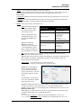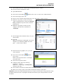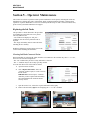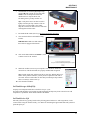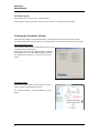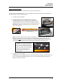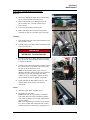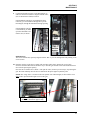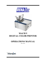
1
MACH 5 DIGITAL COLOR PRINTER OPERATIONS MANUAL Rev 1-31-14 SAFETY PRECAUTIONS THIS EQUIPMENT PRESENTS NO PROBLEM WHEN USED PROPERLY. HOWEVER, CERTAIN SAFETY RULES SHOULD BE OBSERVED WHEN OPERATING THE DIGITAL COLOR PRINTER. BEFORE USING THE PRINTER, YOU SHOULD READ THIS MANUAL CAREFULLY AND FOLLOW THE RECOMMENDED PROCEDURES, SAFETY WARNINGS, AND INSTRUCTIONS: Keep hands, hair, and clothing clear of rollers and other moving parts. Avoid touching moving parts or materials while the machine is in use. Before clearing a jam, be sure machine mechanisms come to a stop. Always turn off the machine before making adjustments, cleaning the machine, or performing any maintenance covered in this manual. The power cord and power supply supplied with the machine should be plugged into a properly grounded, easily accessible wall outlet near the machine. Failure to properly ground the machine can result in severe personal injury and/or fire. The power cord and wall plug is the primary means of disconnecting the machine from the power supply. DO NOT use an adapter plug on the line cord or wall outlet. DO NOT remove the ground pin from the line cord. DO NOT route the power cord over sharp edges or trap it between furniture. Avoid using wall outlets that are controlled by wall switches or shared with other equipment. Make sure there is no strain on the power cord caused by jamming between equipment, walls or furniture. DO NOT remove covers. Covers enclose hazardous parts that should only be accessed by a qualified service representative. Report any cover damage to your service representative. This machine requires periodic maintenance. Contact your authorized service representative for required service schedules. To prevent overheating, do not cover the vent openings. Use this equipment only for its intended purpose. In addition, follow any specific occupational safety and health standards for your workplace or area. This manual is intended solely for the use and information of Neopost USA, its designated agents, customers, and their employees. The information in this guide was obtained from several different sources that are deemed reliable by all industry standards. To the best of our knowledge, that information is accurate in all respects. However, neither Neopost USA, Inc. nor any of its agents or employees shall be responsible for any inaccuracies contained herein. Memjet® is a registered trademark. All other trademarks are the property of their respective holders. All rights reserved. No part of this book may be reproduced or transmitted in any form or by any means, electronic or mechanical, including photocopying, recording, or any information storage and retrieval system, without permission in writing from the publisher TABLE OF CONTENTS Table of Contents Section 1 – Getting Acquainted ...................................................................................1 Front View .......................................................................................................................... 1 Rear View ........................................................................................................................... 2 Print Engine Area ................................................................................................................ 3 Behind the Ink Tank Door .................................................................................................... 4 Section 2 – Installing the Printer ..................................................................................5 Transport Inspection ........................................................................................................... 5 Tools Needed ...................................................................................................................... 5 Choosing the Location ......................................................................................................... 6 Operating Conditions .......................................................................................................... 6 Unpacking ........................................................................................................................... 7 Accessory Box Contents.......................................................................................................................... 8 Removing the cardboard Shipping Insert and Shipping Tape ................................................ 9 Installing Media Guides ..................................................................................................... 10 Connecting the Printer ...................................................................................................... 12 Plugging in the Printer .......................................................................................................................... 12 Powering the Printer ON and OFF ........................................................................................................ 12 Connecting to the Computer ................................................................................................................ 13 Minimum Computer System Requirements ......................................................................................... 13 Installing the Printer Software (Driver & Toolbox) ............................................................. 14 Connecting the Printer via Network (Ethernet Port) ............................................................................ 17 Installing the Ink Tanks...................................................................................................... 19 Ink Tank Anatomy ................................................................................................................................. 19 Procedure (Installing the Ink Tanks): .................................................................................................... 20 Installing the Printhead Cartridge ...................................................................................... 22 Printhead Cartridge Protective Packaging ............................................................................................ 22 Procedure (Installing the Printhead Cartridge) .................................................................................... 24 Envelope Printing Attachment Kit ..................................................................................... 28 Installing/Removing the Head Media Guide......................................................................................... 28 Installing/Removing the PPS Spacers ................................................................................................... 30 Section 3 – Operating the Printer .............................................................................. 31 Control Panel Functions .................................................................................................... 31 Printer Status Light Indicators ........................................................................................... 32 Setting up the Feed ........................................................................................................... 35 Printer Driver Properties ................................................................................................... 38 i TABLE OF CONTENTS Using the Toolbox Utility ................................................................................................... 44 Printing ............................................................................................................................. 51 Printhead Cartridge Conditioning ......................................................................................................... 51 Section 4 – Software Setup Information..................................................................... 53 General Software Setup Info ............................................................................................. 53 Adobe® Acrobat/Reader Setup Tips ................................................................................... 54 Setting Up a Job in Satori Bulk Mailer® ............................................................................... 55 Setting Up a Job in Microsoft Word® (2007) ....................................................................... 62 Section 5 – Operator Maintenance ............................................................................ 66 Replacing the Ink Tanks ..................................................................................................... 66 Cleaning Ink Tank Contacts & Prism ..................................................................................................... 66 Ink Tank Storage & Shelf Life ................................................................................................................ 67 Ink Tank Service Life ............................................................................................................................. 67 Ink Tank Disposal .................................................................................................................................. 68 Cleaning the Printhead Cartridge ....................................................................................... 68 Replacing the Printhead Cartridge ..................................................................................... 70 Printhead Storage & Shelf Life .............................................................................................................. 71 Printhead Service Life ........................................................................................................................... 71 Printhead Disposal ................................................................................................................................ 71 Inspecting & Cleaning the Lip of the Capping Station ......................................................... 72 Inspecting the Wiper Roller ............................................................................................... 73 Cleaning/Replacing Service Station Items .......................................................................... 74 Removing the Service Station ............................................................................................................... 74 Cleaning the Service Station ................................................................................................................. 76 Installing the Service Station ................................................................................................................ 79 Still Experiencing Print Quality Issues? ................................................................................................. 82 Inspecting/Replacing the Waste Ink Tray ........................................................................... 83 Replacing the Sheet Separators ......................................................................................... 84 Clearing Media Jams ......................................................................................................... 84 Cleaning the Printer Body.................................................................................................. 86 Cleaning the Feed Rollers and Forwarding Rollers.............................................................. 86 Cleaning the Encoder Wheel.............................................................................................. 86 Cleaning the Feed Sensor .................................................................................................. 87 Cleaning Other Items inside the Print Engine ..................................................................... 88 Grit Rollers (Media Transport Rollers) .................................................................................................. 88 Media (Paperpath) Sensors .................................................................................................................. 88 Capping Station Lip ............................................................................................................................... 88 Paperpath Surfaces ............................................................................................................................... 88 Printing Platen Surface ......................................................................................................................... 88 Cleaning the Ink Revolver Couplings .................................................................................................... 90 ii TABLE OF CONTENTS PRINTER MAINTENANCE SCHEDULE................................................................................... 91 Preparing Printer for Transport ......................................................................................... 93 Local relocation .................................................................................................................................... 93 Remote relocation or shipping ............................................................................................................. 93 Section 6 – Troubleshooting Guide ............................................................................ 95 Print Quality Issues: .......................................................................................................... 95 Examples of Print Quality Issues (including possible causes and solutions) ......................................... 96 The Ink Tank(s)................................................................................................................ 102 The Printhead Cartridge .................................................................................................. 103 The Printer ...................................................................................................................... 105 Dots or Lines Printed on Media .......................................................................................................... 105 Power Problems ................................................................................................................................. 105 Service Station Problems .................................................................................................................... 106 Interface Communication Problems ................................................................................................... 107 Feeding Problems ............................................................................................................................... 108 Errors and Warnings........................................................................................................ 109 Printer Alert Window Messages ......................................................................................................... 109 Toolbox System Status Messages ....................................................................................................... 110 Appendix A – Printer Specifications ......................................................................... 114 Appendix B – Supplies and Optional Hardware ........................................................ 115 Appendix C – Quick Reference Info .......................................................................... 117 Control Panel Light Sequences – Quick Reference ............................................................ 117 Driver Properties Printing Adjustments - Quick Reference ............................................... 118 iii TABLE OF CONTENTS NOTES ______________________________________________________ ______________________________________________________ ______________________________________________________ ______________________________________________________ ______________________________________________________ ______________________________________________________ ______________________________________________________ ______________________________________________________ ______________________________________________________ ______________________________________________________ ______________________________________________________ ______________________________________________________ ______________________________________________________ ______________________________________________________ iv SECTION 1 GETTING ACQUAINTED Section 1 – Getting Acquainted Front View 1. 2. Control Panel – Provides printer controls. See "Control Panel Functions" section 3. Rear Media Support Guide – Provides the proper angle to enhance paper feeding and separation. 4. Media Support Wedge – Allows for adjustments in stack angle, based on media type and length. Helps to force the media against the separation area. Narrow and wide wedges are provided with the printer to accommodate different media widths. 5. Adjustable Media Side Guide – Adjusts to hold the paper/media against the Media Registration Side Guide. 6. Media Registration Side Guide – All media is registered against this guide. It has two positions. Inner position for media measuring 3" to 8.5" in width. Outer position for media measuring 8.6" to 9.5" in width. 7. Sheet Separator Locking Screws – These thumb screws (four total) are used to secure the positions of the sheet separators. 8. 9. Top Cover – Provides access to the Print Engine. Side Guide Locking Knob – Used to secure the position of the side guide. Ink Tank Door – Hinged door access to the Service Station, Ink Tanks and Waste Ink Tray. NOTE: On earlier units the cover above the Ink Tank Door had to be removed to access the Service Station. 1 SECTION 1 GETTING ACQUAINTED Rear View Main Power Switch, Receptacle and Fuse – Plug in AC power cord here. Switch turns main power ON/OFF. Fuse provides over-current protection. Fuse rating: 2.5A, 250V, slow blow. CAUTION: Make sure power cord is disconnected from printer before checking/replacing fuse. 1. 2 WARNING: Press the ON/OFF Button, located on the control panel, to properly power-down the print engine. Wait until all control panel lights turn off, before you turn off the main power switch. For best system performance, it is recommended to keep the print engine powered-up at all times. 2. 3. USB Port Connection – (USB 2.0) The USB cable attaches to the printer here. 4. Sheet Separators – Used to separate a single piece of media from the stack. There are four sheet separators on this printer. 5. Feed Rollers – Used to deliver the bottom piece of media from the stack, through the sheet separation area, and present it to the first set of transport rollers. 6. Media Support Wedge Thumb Screw – Used to secure the Media Support Wedge to the Rear Media Support Guide. 7. Counter – LCD displays number of pieces fed into the Print Engine. Reset button zeros counter. NOTE: The number of pieces fed will normally be higher than the number of pieces printed. 8. Rear Media Support Guide Knob – Attaches the Rear Media Support Guide to the body of the printer. Network Connection – (Ethernet) The network cable plugs in here. SECTION 1 GETTING ACQUAINTED Print Engine Area Print Engine with printhead cartridge installed and printhead latch closed. 1. 2. Antistatic Brush Assembly – Contains an antistatic brush that is used to help reduce static energy and remove paper dust from the media. This assembly also contains pressure rollers and fingers that help guide the paper into the print engine. Printhead Latch – When closed; the Ink Revolver Couplings extend/connect with the Printhead Cartridge. When opened; the Ink Revolver Couplings retract/disconnect from the Printhead Cartridge, providing access for Printhead Cartridge installation/removal/replacement. WARNING! Never attempt to open the Printhead Latch manually, severe damage will result. Use the Printhead Release button function in the Toolbox utility on your PC, 3. Print Ink Channels Button* – Prints 5 bars (1 bar from each ink tank) to indicate how well the Printhead Nozzles are working. Lightly press the button with a non-conductive tool. *Same function can be accessed through the Printer Toolbox Diagnostics screen on your computer. 4. Ink Revolver Couplings – Connects the ink hoses to the Printhead Cartridge. The Printhead Latch extends and retracts the couplings from the Printhead. 5. Printhead Latch Release Button* – Initiates a Printhead Latch release cycle. If system is primed with ink; a “System Deprime” cycle will occur before the Printhead Latch is released. Lightly press the button with a non-conductive tool. *Similar function can be accessed through the Printer Toolbox User Interface screen on your computer. If you are replacing the printhead; it is best to use the “Release Printhead” button from the Toolbox utility. Clamshell Latches – Lift both latches at the same time to release and swing open the “Clamshell” (top section of the Print Engine). 6. Do NOT open the Clamshell while the Printer is operating. Do NOT let the Clamshell drop. Close it gently and then release the latches slowly. Make Sure the Clamshell is closed and locked before operating. 7. Printhead Cartridge – Memjet® Printhead. Capable of printing an 8.5" wide full color print area. 3 SECTION 1 GETTING ACQUAINTED Behind the Ink Tank Door 1 4 2 3 Ink Tank Securing Latches – Used to hold the Ink Tanks securely into the slots and against the electrical contacts within the print engine. 1. CAUTION! Before removing/installing Ink Tanks; please be sure to power-down the Print Engine or press the “Replace Ink Tanks” button, in the Toolbox. If this rule is not followed damage to the Ink Tanks may result, rendering them unusable. NOTE: Please be sure that both sides, at the bottom part of the latch, are engaged. 2. Ink Tanks – Five Ink Tanks are used in the printer. Cyan (C), Yellow (Y), Magenta (M), Black (K), Black (K) 3. Waste Ink Tray – The purpose of this tray is to catch the waste ink produced by the system. This tray is filled with absorbent material. This tray must be replaced when it becomes saturated. Please inspect routinely. The tabs located at the left and right sides of the tray secure the tray to the print engine frame. Please be sure the tabs “click” into the frame, to secure the tray's position. 4. Service Station – Contains four major components. - Wiper Roller Assembly - cleans the Printhead Cartridge of excess ink and debris. - Capping Station - keeps the Printhead capped, hydrated and protected when not in use. - Printing Platen - provides the base to support media during feeding and printing. - Tray – holds all of the above components and captures the waste ink. The waste ink eventual makes its way from the Service Station Tray into the Waste Ink Tray. Please refer to the “Operator Maintenance” section for information on how to properly maintain the Service Station and its components. 4 SECTION 2 INSTALLING THE PRINTER Section 2 – Installing the Printer Before using the Digital Color Printer the following must be done: • Transport Inspection. Upon delivery; inspect packaging and report any issues to the Carrier • Gather Tools. • Choose a location for the Printer • Unpack and verify Accessory Box contents • Attach the Media Guides to the Printer • Remove the Service Station Transport Tab and Shipping Tape • Plug in the Printer and Connect it to the Computer • Install the Printer Software (Driver & Toolbox) • Install the Ink Tanks • Install the Printhead • Install the PPS spacers (if needed) Transport Inspection The printer is shipped in appropriate packaging so that, under normal shipping conditions, it reaches its destination without damage. NOTICE: Report damage to the carrier. The carrier is liable for any damage during transport. Transport and storage should take place under the following conditions: - At temperatures between -25°C and +50°C (-13 °F to 122 °F). - At a relative air humidity between 5% and 95%, non-condensing. - At an atmospheric pressure between 70 kPa and 105 kPa. Exposure to conditions that are not permissible may lead to damage which is not externally visible. IMPORTANT Please save the packaging materials for future use! It will be required if you ever need to ship the printer. Before shipping; please refer to the section titled “Preparing the Printer for Transport”. Tools Needed • • • • • Knife and scissors to open packaging Carpenters Level (recommend using 18” or longer level) Protective, nitrile powder-free gloves should be worn to avoid getting ink on hands when removing protective packaging materials from the ink coupling areas, the Ink Tank areas, and when installing/removing Printhead Cartridge and Ink Tanks. Distilled or de-ionized water Non-abrasive, lint free cloths 5 SECTION 2 INSTALLING THE PRINTER Choosing the Location The Digital Color Printer should be placed on a sturdy, level, worktable or cabinet; at least 9 inches from any walls. Protect the Digital Color Printer from excessive heat, dust, and moisture – avoid placing it in direct sunlight. Work-Table Surface Must be Level IMPORTANT! Level the Table, NOT the Printer! The surface that the printer is placed upon must be level, front to back and side to side. Use a carpenter’s level (bubble level) to verify that the surface is level. If the surface is not level the printer will not perform properly; which can lead to damage not covered under warranty. Why is this Important? The printer’s ink delivery systems, and waste ink drainage system, depend on the table surface being level to perform properly. If this rule is not followed you will experience print quality issues and ink waste draining issues that could cause damage to the printer and void the warranty. - Level the Table surface, NOT the Printer. - Do NOT use the Toolbox utilities “Tilt” readings to level the printer or table. - Use an accurate level (i.e. bubble level that is at least 18” long), to check that the table surface is level (front to back and left to right). It is not acceptable to use your “cell phone app” to check level. - Do NOT shim, raise or otherwise modify the printer, or feet of the printer, in any way. - If the table surface cannot be leveled then the printer should not be placed on it. - If the table is not sturdy then the printer should not be placed on it. - Do NOT move the printer while the power is on. Operating Conditions Operation should take place under the following conditions: - At temperatures between +15°C and +35°C (59 °F to 95 °F). - At a relative air humidity between 20% and 80%, non-condensing. - At an atmospheric pressure between 70 kPa and 105 kPa. - Printer and Print Engine should be protected from excessive environmental debris/dust. - Printer must be placed on a “Sturdy/Level” surface. Exposure to conditions that are not permissible may lead to damage which is not externally visible. Allow the printer, printhead and ink tanks to acclimate to ambient temperature before using the printer. 6 SECTION 2 INSTALLING THE PRINTER Unpacking Please refer to the unpacking sequence, shown below. NOTE: Packaging materials may vary slightly from what is shown below. Please save the packaging in a safe place, for possible future use. Two people will be required to safely lift the printer and place it onto a sturdy, level work table. IMPORTANT: WORK TABLE SURFACE MUST BE LEVEL! Level the Table, NOT the Printer! 1 2 3 4 5 6 Save the Packaging for possible future use. 7 SECTION 2 INSTALLING THE PRINTER Accessory Box Contents Accessories Box The following items are included with your printer: Qty [Image Reference] Description 5 [A] Ink Tanks (packed in foam molds) - Cyan, Magenta, Yellow, Black, Black 1 [B] Printhead Cartridge and packaging 1 [C] Rear Media Support Guide - thumb screw attached to printer 1 [D] Service Station (now pre-installed in printer) 1 [E] Wide Media Support Wedge - mounting hardware attached to item C Ink Tank Packaging B A C E D F 1 [F] Narrow Media Support Wedge - mounting hardware attached to item C 1 [G] Media Registration Side Guide - mounting screws attached to printer 1 [H] Adjustable Media Side Guide - mounting screws attached to printer 1 [I] USB Cable 1 Ethernet Cable, CAT5 (not shown) 1 [J] Power Cord 1 [K] Operation CD - contains printer software (driver) and operations manual (in pdf format) G I H J Note: Ink Tanks and Printhead Cartridges can be purchased through your local Rena Systems Dealer. To locate a Rena Systems Dealer, please visit our website: www.renausa.com See “Appendix B” for supplies information. 8 K SECTION 2 INSTALLING THE PRINTER Removing the cardboard Shipping Insert and Shipping Tape WARNING! To avoid possible damage to the printer; do NOT plug-in, or power-up, the printer until all shipping materials have been removed; as described below. 1. Open the Top Cover. 2. Carefully release both latches (one on either side of the Print Engine), and lift up with both hands, to gently swing open the Print Engine Clamshell. CAUTION HOLD ONTO BOTH LATCHES WHEN OPENING AND CLOSING THE PRINT ENGINE CLAMSHELL TO PREVENT DAMAGE. DO NOT ALLOW THE ASSEMBLY TO DROP OR SLAM CLOSED. 3. Remove the cardboard “Shipping Insert” [A], by pulling up on both red tabs at the same time. The “Shipping Insert” secures the Service Station during printer transport. 4. Remove the Tape [B]. The tape wraps around the underside of the Clamshell to secure the Head Media Guide. (If necessary, wipe off any tape residue from the Head Media Guide surface [C].) 5. Gently close and latch the Clamshell. 6. Close the Top Cover. 9 SECTION 2 INSTALLING THE PRINTER Installing Media Guides The screws needed to attach the side guides to the printer are located under the shipping tape in their respective positions. 10 1. Begin by installing the Media Registration Side Guide using the two screws [1] provided: 2. Next install the Adjustable Media Side Guide using the two screws [2] provided. SECTION 2 INSTALLING THE PRINTER 3. Attach the Rear Media Support Guide using the Knob [3] and washer provided. Remove the knob and washer from the printer. Position the Rear Media Support Guide against the frame of the printer. The two outer holes in the guide fit over the socket head screws; as shown. Install the washer, then install and tighten the Knob. 4. 3 Install the desired Media Support Wedge using the mounting hardware [4]; as described below. Choose the appropriate Media Support Wedge for your application: Wide Media Support Wedge [5] – For media that is 8 to 9.5 inches wide. Narrow Media Support Wedge [6] – For media that is 3 to 8 inches wide. 5 The Anchor Plate [7] fits into the slot, from the underside of the Rear Media Support Guide. Position the Media Support Wedge so the upper and lower holes fit onto the two tabs from the Anchor Plate. The washer [8] goes between the Thumb Screw [9] and the Media Support Wedge. The Thumb Screw is inserted down through the washer, then through the center hole in the Media Support Wedge and into the threaded hole in the Anchor Plate. Tighten the thumb screw to secure the Media Support Wedge onto the Rear Media Support Guide. 6 7 8 9 11 SECTION 2 INSTALLING THE PRINTER Connecting the Printer Plugging in the Printer • • • Check to make sure the Main Power Switch [1] is in the OFF position. Plug the Power Cord into the receptacle [1] at the rear of the Printer. Connect the other end of the Power Cord to a compatible AC Outlet that supplies 100-240 volts AC, 50/60 Hz and provides earth ground. CAUTION DO NOT USE AN ADAPTER PLUG OR EXTENSION CORD TO CONNECT THE PRINTER TO THE WALL RECEPTACLE. DO NOT USE OUTLETS CONTROLLED BY WALL SWITCHES. DO NOT USE AN OUTLET THAT SHARES THE SAME CIRCUIT WITH LARGE ELECTRICAL MACHINES OR APPLIANCES. Powering the Printer ON and OFF Powering-Up the Printer: 1. 2. Turn ON the Main Power Switch [1]. Press the Control Panel’s ON/OFF Button. Wait about 45 seconds for the print engine to power-up (ON/OFF button will illuminate). Powering-Down the Printer: 1. 2. Press the Control Panel’s ON/OFF Button. Wait for the print engine to power-down (all Control Panel Buttons will turn OFF). Turn OFF the Main Power Switch [1]. CAUTION BEFORE POWERING OFF THE MAIN POWER SWITCH, ALWAYS POWER DOWN THE PRINT ENGINE, USING THE ON/OFF BUTTON. IF THIS RULE IS NOT FOLLOWED DAMAGE TO THE PRINTHEAD AND OR INK SYSTEM CAN RESULT. FOR BEST SYSTEM PERFORMANCE; IT IS RECOMMENDED TO KEEP THE PRINT ENGINE POWERED-UP (ON/OFF LIGHT ILLUMINATED) AT ALL TIMES. 12 SECTION 2 INSTALLING THE PRINTER Connecting to the Computer The Printer connects to the computer through the USB port [2]. A Network port [3] is also provided; for connecting the printer to a network environment. IMPORTANT: Do NOT connect the printer to the computer, until prompted to do so, during the printer driver installation process. See “Installing the Printer Software” section. Before installing the printer software (Toolbox and Driver); you should temporarily disable all Antivirus programs and Firewalls. In addition; you must be logged onto the system with full administrative privileges (admin rights). Minimum Computer System Requirements • • • • • • • • • Windows XP, Windows Vista, Windows 7. Supports 32 and 64 bit systems. You must have administrative privileges on the system. Pentium II, 2 GHz minimum (Pentium Dual Core, 2.5 GHz or better, is optimal) System memory – 2 GB minimum; or as recommended for your operating system. At least 10 GB free hard-disk space. Microsoft Internet Explorer 6.0 or higher. Java version 6. (If you have Java 7 or higher installed; you may need to load Java 6 also, or the Toolbox may not open properly.) CD/DVD drive USB 2.0 port (ports will be identified as “USB2” or “Enhanced” in the Device Manager) Microsoft .Net Framework version 3.5 (for 32 bit systems) or Microsoft .Net Framework version 4 (for 64 bit systems) must be installed. Note: Even if you have a higher .NET Framework version installed; version 3.5 or 4 must also be installed, or the Toolbox will not open. How to check your system for the minimum system requirements, shown above: Right click on "My Computer" and select Properties. The system information, including Operating System, Processor Info and Memory info will be displayed under the "General" tab. How to check your system for the versions of "Microsoft .NET Framework” installed. From the Control Panel; open "Add or Remove Programs" and look for "Microsoft .NET Framework 3.5..." or "Microsoft .NET Framework 4..."in the list. You can obtain "Microsoft .Net Framework 3.5 or 4" via the Microsoft website. http://www.microsoft.com How to check your system for the version of "Java" installed. From the Control Panel; open "Add or Remove Programs". Look for "Java(TM) ..." in the list. You can obtain Java from the following website: www.java.com There are also tools on the Java site to help you detect if you have java installed and what version is installed. 13 SECTION 2 INSTALLING THE PRINTER Installing the Printer Software (Driver & Toolbox) For the Printer software to operate properly check that the computer system meets the minimum requirements. See section titled “Minimum Computer System Requirements”, on previous page. NOTE: If you are updating the Digital Color Printer (M Series) printer software (printer driver and toolbox utility); please be sure to Uninstall the old software before installing the new software. Use the “Uninstall” feature found on your computer system under All Programs, “Memjet”, “M Series Driver”. IMPORTANT: Before installing the Printer software (Toolbox and Driver), you should temporarily disable all antivirus programs and firewalls. In addition, you must be logged onto the system with full administrative privileges (admin rights). NOTE: Even if you plan to use the printer via an Ethernet Network Connection; your initial connection to the printer must be done via USB; in order to access the Network Configuration Settings in the Toolbox. Do NOT plug in the USB cable until prompted to do so. PROCEDURE 1. Disconnect the USB cable connection from the printer; if you plugged it in already. 2. Power-up the Printer. Turn ON the Main Power Switch, then press the Control Panel’s ON/OFF button. Wait about 45 seconds for the print engine to power-up (ON/OFF button will illuminate). 3. Insert the CD, supplied with the printer, into your CD drive. If the “Launch Menu” window does not automatically open in your browser. Locate and run the “MENU_LAUNCH.htm” file, located on the root directory of the CD. 4. When the Digital Color Printer Operation CD “Launch Menu” window opens on the computer screen; Click “Install Printer Software”. NOTE: If you receive a Windows security or authorization warning, click on “YES” or “Continue Anyway”. Tip: If you are unable to start the software installation using the button in the “Launch Menu”: Browse to the CD. Locate and open the Printer Drivers folder. Located and run “WinSetup.exe” to start the install. 5. The “Install Printer Software” window opens on the computer screen. Make sure the computer system meets the minimum requirements and you have followed the other instructions on the screen. Click “Install Printer Software”. 14 SECTION 2 INSTALLING THE PRINTER 6. The License Agreement window opens. Carefully read the “Software License Agreement”. If you agree to the terms, check “I accept…” then click Next>. 7. After a few moments the “Printer Connections” window opens. Click “Configure to print using USB”. Then click Next>. NOTE: Even if you plan to use the printer via an Ethernet Network Connection; your initial connection to the printer must be done via USB; in order to access the Network Configuration Settings in the Toolbox. 8. After a few moments the “Installing Printer Software” window opens and begins downloading the software. 9. As the software loads, the “Would You Like to Install This Device Software?” window appears. Click Install. 10. The “Connect Device Now” window opens. Connect the USB cable, from the computer to the printer, at this time. Don’t click on either button (Back or Cancel). The software will automatically continue once it recognizes the printer (printer powered on and USB cable connected). 15 SECTION 2 INSTALLING THE PRINTER 11. The “Finished software installation” window opens. Do not select (check) the Print Test Page as the Printer is not set up yet. If desired; you can select (check) the “Set this printer as the default printer” at this time. Then click Next>. 12. The M Series Driver welcome window will still be open. Click Exit to close this window. 13. Restart the computer to complete the installation. The “M Series Driver” should now be available in your “Printer and Faxes” or “Devices and Printers” folder. Tip: After you have completed printer setup (ink tanks installed, printhead cartridge installed, media feed setup); it is a good idea to print a test page from the printer driver to confirm that the printer driver and printer are communicating. This is done by right-clicking on the “M Series Driver” and selecting “Properties” (Printer properties in Win7). Then click on the “Print Test Page” button. 16 SECTION 2 INSTALLING THE PRINTER Connecting the Printer via Network (Ethernet Port) Valid for M-Series Printers with firmware version 20130820 installed in printer and R12.01 M-Series Driver installed on computer. They should be used as a set. 1. If you haven’t already done so; install the Printer Software (M Series Driver and Toolbox), via USB, by following the instructions in the previous section. Note: Initially the USB connection is needed in order to configure the printer’s internal network settings. Once the software installation is complete; you can proceed to the next step. 2. Open the M Series “Toolbox” utility. To open the Toolbox utility; click on Start, All Programs, Memjet, M Series Driver, Toolbox. The Toolbox will open in a Web Browser (Example: Internet Explorer) window. Tip: If you receive warning that Windows Firewall has blocked some features of this program. Please select Private Networks and then click on Allow Access. 3. From the User Interface window of the Toolbox; click on “Network Config”. Note: Your Toolbox layout may look different then shown. 4. When the “Network Configuration” window appears; configure the printer's network settings as needed. See example. Check with your IT support person for help with these settings. Be sure to click on “Submit” after entering new information. NOTE: The information shown on this page is just an example. You must use settings that are compatible with your network and settings that are not in direct conflict with other devices on the network. AutoIP Network Tip: For network systems that automatically assign or obtain the IP Address; make sure the appropriate items (dhcp, bootp, autoip), for your particular network, are checked (selected). Static IP Network Tip: Running "ipconfig", from the Command Prompt of a computer that is being used on the same network, may help you define some of the information needed for this setup. In general you can use the same "Subnet Mask" and "Default Gateway" that are shown in the "Windows IP Configuration". However you need to provide a unique "IP Address" for the printer. For example if the "Windows IP Configuration", IP Address for your computer's connection is shown as 192.168.100.222 you may be able to use 192.168.100.223 for the printer; if this IP Address is not in use by some other device. If you want to check for an open IP Address you can ping the address before you save the settings and connect the printer. Type "ping [ip address]" (Example: ping 192.168.100.223) at the command prompt. An open IP Address will show "Request timed out". An IP address that is in-use and working will show replies (Reply from 192.168.100.223:....) Check with your IT support person for help with these settings. 5. Using a Cat5 network cable; connect the printer to your network via the Ethernet port. 17 SECTION 2 INSTALLING THE PRINTER 6. Click on “Diagnostics”. The “Diagnostics” window will open; displaying a lot of information about the printer. This information will include the Network Status and configuration settings. 7. If the “Network Status:” is shown as “disconnected”; click on the refresh button in the browser window. If you have entered compatible network settings for your network and the printer; the "Network Status:" line in the Diagnostics window should change from "disconnected" to "connected". If the status doesn’t change to “connected” please contact your IT support person for help with the network settings. 8. Run the Printer Software (M Series Driver, R12.01) installation again; but this time choose "Add another printer". 9. When prompted to choose the Printer Connection; select "Configure to print over the Network". Then click Next. The install program will search the network for printers. It should automatically locate the "M_Series" printer at the IP address provided by the network or that you configured in step 4. In this example the M_Series printer has the IP Address 192.168.100.251. Note: If the driver install program cannot locate the printer automatically, then you will be presented with a window to enter the Host name and IP Address for the printer. Enter the IP Address for the printer and click Next (You do NOT need to enter a Host name). If the printer is found at the IP Address provided; the driver install will continue automatically (skip to 10). If the printer is not found then, in general, you have not provided a valid IP Address or network configuration for the printer. In this case CANCEL the driver install and repeat from Step 2. Please obtain help from your IT support people. 10. Select the "M_Series" printer that is displayed. Then click Next 11. When the “Finished software installation” window appears; displaying “Network Connection Successful”; select if you want to “Print Test Page” or “Set this printer as the default printer”. Then click Finish. If selected, a test page will be sent to the printer to be printed. Tip: To help distinguish between multiple M-Series Drivers on your system; Open the “Printers and Faxes” (Devices and Printers) folder. Then rename the network configured printer “M Series Driver (Network)” and the USB configured printer “M Series Driver (USB)”. Opening (launching) the “Toolbox” utility over an Ethernet connection: Valid for M Series Driver version R12.01 and printer firmware version 20130820. To open the Toolbox utility; click on Start, All Programs, Memjet, M Series Driver, Toolbox. If you have more than one copy of the M-Series Driver installed, you may be prompted to choose the device you want the Toolbox to connect to. Be sure to choose the proper device. Example: M-Series Driver - configured for USB. Suggestion: Rename to “M Series Driver (USB)” M-Series Driver (Copy 1) - configured for Network. Suggestion: Rename to “M Series Driver (Network)” 18 SECTION 2 INSTALLING THE PRINTER Installing the Ink Tanks The Digital Color Printer uses five Ink Tanks (two Black, one Cyan, one Magenta, and one Yellow). The Ink Tank is a delicate, precision device. Handle with extreme care to avoid damage. Ink Tank Anatomy The ink used in this system may be harmful if swallowed. Keep new and used printhead cartridges and ink tanks out of reach of children. Discard unwanted printhead cartridges and empty ink tanks immediately. Before attempting to install or remove Ink Tanks; press the button labeled “Replace Ink Tanks” in the Toolbox, or Power-down the printer using the ON/OFF button. If this rule is not followed the QA Chip on the Ink Tank may be damaged, which will render the Ink Tank unusable. 19 SECTION 2 INSTALLING THE PRINTER Procedure (Installing the Ink Tanks): This procedure assumes that you are installing Ink Tanks into a printer that doesn’t have any Ink Tanks installed. If you are replacing an empty Ink Tank, please refer to the “Replacing the Ink Tanks” section. Install the Ink Tanks as follows: 1. Power the Printer ON. Plug in the printer. Turn the printer’s Main Power Switch ON; then press the control panel’s ON/OFF button. Wait about 45 seconds for the print engine to power-up (ON/OFF button will illuminate). 2. Open the M Series Toolbox. Go to All Programs, select the “Memjet” folder, select the “M Series Driver” folder and Open the “Toolbox”. Tip: If you receive warning that Windows Firewall has blocked some features of this program. Please select Private Networks and then click on Allow Access. A web browser will open and display the “User Interface” screen. On the left side of the screen you will see information about the System Status and Ink levels. With no Ink Tanks installed all Ink status levels for “CKYMK”, will be displayed with a question mark (?) below each color position and the colors are not filled-in. 3. Click the button labeld “Replace Ink Tanks”, located in the Toolbox User Interface screen. This disconnects Printer communication with the Ink Tanks and allows safe installation and replacement. Once the “Confirm” screen, shown to the right, displays, it is safe to install/remove Ink Tanks. IMPORTANT: DO NOT press “Continue” until after you have installed the Ink Tank(s) and closed the Ink Tank Latches. 20 4. Open the Ink Tank Door (hinged at bottom). 5. Open the Ink Tank Securing Latches [A]. 6. Remove the new Ink Tank(s) from packaging. SECTION 2 INSTALLING THE PRINTER 7. Insert the new Ink Tanks (label side up) into their appropriate color slots [B]. CAUTION! Be sure each Tank is installed into the proper color slot. If you force the Ink Tank into the wrong slot, you will contaminate the ink system and professional service will be required. INSTALLATION TIP: To help insure that the Ink Tanks are seat properly. Insert the Ink Tank into the appropriate Ink Station, then pull the Ink Tank back about an inch and push forward firmly. This will help insure that the “septum needles” penetrate the seals on the Ink Tanks. 8. Close and lock all three Ink Tank Securing Latches. IMPORTANT: Make sure both sides of the Latch are engaged at the bottom. 9. Click on the button labeled “Continue”, in the Confirm screen of the Toolbox. 10. Watch the Toolbox screen on your computer. You should see all the ink colors fill-in; if all the Ink Tanks are properly installed and recognized. If an Ink Tank color does NOT fill-in, and a question (?) mark or “out” condition is displayed below the ink color; this indicates that the printer does not recognize the Ink Tank (Unable to communicate with QA Chip) or the ink level sensor doesn’t see any ink in the Tank. Verify that the Ink Tank Securing Latches are fully closed and locked. Then click on the button labeled “Refresh Ink Levels”. If the ink color still does not fill in; the QA Chip contacts or Ink Level Prism may need to be cleaned. Please refer to the “Operator Maintenance” section for information on “Cleaning Ink Tank Contacts & Prism”. Tip: Even new Ink Tanks can have dirty QA Chip contacts. This is not always visible to the eye. 11. Close the Ink Tank Door. NOTE: If a Printhead Cartridge is not installed the Systems Status line in the Toolbox will display the “MISSING PRINTHEAD message. To install the Printhead Cartridge; please proceed to the section titled “Installing the Printhead Cartridge”. 21 SECTION 2 INSTALLING THE PRINTER Installing the Printhead Cartridge The Digital Color Printer uses a single Memjet® printhead cartridge. The Printhead Cartridge is a delicate, precision device. Handle with extreme care to avoid damage and issues that could degrade print quality. ATTENTION If you experienced fuzzy print quality or an abrupt failure in a particular area of nozzles on the previous printhead, we recommend that you have the service station inspected/cleaned and the wiper roller replaced before installing the new printhead. Failure to do so will increase the chance of damage to the new printhead. Service station maintenance and wiper roller replacement should only be performed by a qualified/trained person. Please contact your service representative to obtain training or to have them perform this process for you. Printhead Cartridge Protective Packaging 1 & 10 2 3&8 4 Handles Nozzles protective tape Protective cover flaps Protective cover 5 6 7 9 Foil vacuum bag Cardboard packing box Cover retaining clip Electrical contacts tape NOTE: Discard protective tape once it is removed. Do NOT reuse protective tape. Keep all other packaging to store/dispose of old printhead cartridge. The ink used in this system may be harmful if swallowed. Keep new and used printhead cartridges and ink tanks out of reach of children. Discard unwanted printhead cartridges and empty ink tanks immediately. 22 SECTION 2 INSTALLING THE PRINTER CAUTION • • • • • Use electrostatic discharge (ESD) handling precautions. Hold the Printhead Cartridge by the handles ONLY. DO NOT touch the Ink Couplings, nozzle surface or electrical contacts. DO NOT unpack the Printhead Cartridge until the Printer is ready for installation. Once unwrapped, delay in installing the Printhead can compromise print quality due to dehydration. DO NOT place an unwrapped Printhead on any surface before installing. Protect the Printhead at all times from dust, fibers, dirt and other contaminants. CAUTION DO NOT PRY OR MANUALLY LIFT THE PRINTHEAD LATCH OR THE LATCH WILL BREAK. ONLY OPEN THE LATCH USING THE PRINTHEAD RELEASE BUTTON ON THE PRINTER OR IN THE TOOLBOX. NOTICE! Read this procedure, in its entirety, before proceeding! Before you begin this process, you will need to obtain some deionized or distilled water and some lint free cloths. These items will be used to wet the printhead nozzles. NOTE: Do NOT use tap water or paper towels to wet or clean the printhead nozzles. Doing so may cause damage to the printhead cartridge and possible contamination to the ink system. The printhead cartridge and ink supply must be within the operating temperature range ((+15°C to +35°C (59 °F to 95 °F)), before attempting to prime the cartridge with ink and starting to print. When stored at temperatures below the operating range it may take up to 3 hours for a cartridge in its packaging to reach operating temperature. NOTE: Additional packaging will increase the time needed to reach operating temperature. Why is it necessary to wet the printhead nozzles? During the priming process a vacuum is created by the pump, to pull ink from the Tanks into the printhead and ink delivery system. If the printhead nozzles are dry (open); air is pulled in through the printhead nozzles causing the priming process to fail (pump is unable to create a vacuum). By wetting the printhead nozzles this creates a temporary “water seal”, which prevents air from getting pulled into the printhead during the priming process. 23 SECTION 2 INSTALLING THE PRINTER Procedure (Installing the Printhead Cartridge) This procedure assumes that you are installing a Printhead Cartridge into a printer that does NOT have a Printhead Cartridge installed. If your printer already has a Printhead Cartridge installed, and you wish to replace the Printhead Cartridge; please refer to the section titled “Replacing the Printhead Cartridge”. 1. Plug in the printer. Turn the printer’s Main Power Switch ON; then press the control panel’s ON/OFF button. Wait about 45 seconds for the print engine to power-up (ON/OFF button will illuminate). 2. If the Printhead Latch [2] is closed; press the “Printhead Latch Release” button [1]; as shown. Use a non-metallic item (example: plastic pen) to reach through the hole and lightly press the button. 2 The printer will run a routine and then the Printhead Latch [2] will release so it can be opened. Note: The Printhead Latch [2] color may be blue or black. WARNING! If the printhead latch fails to release do not force the latch open. Severe damage will result. Tip: You can perform this same function from your computer by clicking the “Printhead Release” button; found on the “User Interface” screen of the M Series “Toolbox” utility. 3. Open the Printhead Latch fully. 4. If present; Remove the Cap Protectors from the Ink Revolver Couplings [3]. Save these items. They should be used to seal and protect the open ink system when a Printhead Cartridge is not installed. NOTE: Before replacing or re-installing a Printhead Cartridge, please clean the Ink Revolver Couplings. See section titled “Cleaning the Ink Revolver Couplings”. CAUTION DO NOT PRY OR MANUALLY LIFT THE PRINTHEAD LATCH OR THE LATCH WILL BREAK. ONLY OPEN THE LATCH USING THE PRINTHEAD RELEASE BUTTON ON THE PRINTER OR IN THE TOOLBOX. 24 1 SECTION 2 INSTALLING THE PRINTER 5. [A] Carefully remove the Printhead Cartridge from the foil packaging. Tear at notch or cut end with scissors. [B] Remove the protective plastic cover. Hold the Printhead by the handle and unclip the cover from the Printhead. [C] Remove protective strip from the Printhead Electrical Contacts. DO NOT allow removed strip to touch the electrical contacts. [D] Remove protective strip from the Printhead Nozzles. Hold the Printhead by the handle. Pull the strip tab and slowly peel the strip from the Printhead. DO NOT pull the strip at less than a 45° angle from the Printhead surface. DO NOT allow removed strip to touch the Printhead Nozzles. WARNING TO AVOID ELECTRICAL SHOCK OR SHORTING Before installing Printhead, make sure the contacts are DRY! 6. Carefully insert the Cartridge into the compartment at an angle [4], with the Printhead surface facing down and the Ink Couplings facing the Ink Revolver Couplings (ink hoses). Once it is seated, gently tilt the Cartridge forward until it snaps into an upright position [5]. DO NOT FORCE the Cartridge into position. DO NOT close the Printhead Latch at this time. 25 SECTION 2 INSTALLING THE PRINTER 7. Open the Print Engine Clamshell; using with both hands. 8. Using a lint-free cloth soaked with deionized or distilled water, wet the entire Printhead Nozzle area. Be liberal with the amount of water you leave behind on the nozzles (the thin dark line on bottom of printhead cartridge). See images below. Printhead Nozzle Area WARNING: Be careful not to damage the “star rollers” when wiping the printhead. These rollers are designed so they can roll across a wet image, without damaging the image. If the rollers are bent, they will not turn free; causing media feed issues (jamming) and possible damage to the image or media. 9. Immediately after wetting the nozzles. Carefully close and latch the Print Engine Clamshell. CAUTION HOLD ONTO BOTH LATCHES WHEN OPENING AND CLOSING THE PRINT ENGINE CLAMSHELL TO PREVENT DAMAGE. DO NOT ALLOW THE CLAMSHELL TO DROP OR SLAM CLOSED. 10. Now close the Printhead Latch [6]. After a few seconds the Printer will run a “priming routine” that fills the ink system and Printhead with ink. WHAT TO EXPECT: a. b. c. d. 26 After closing the Printhead Latch there will be a ~15 second pause (no noise or motion). Then you will hear the Service Station move to the capping position. Then you will hear the ink pump start to run. At this time, ink should start flowing through all the tubes, in and out of the printhead. If you see this occurring, then the priming process is working. SECTION 2 INSTALLING THE PRINTER If ink doesn’t start filling all tubes during the first 5-seconds of the first ink pump cycle: Using deionized or distilled water; re-wet your lint-free cloth generously. Don’t wait for the pump to stop, open the clamshell and wipe along the Nozzles with the cloth, back and forth twice. Immediately after re-wetting the nozzles, carefully close the clamshell. The ink tubes should begin filling. Tip: To save time; prepare a pre-wetted lint free cloth before you begin the priming process. If you reach the end of the second pump activation cycle and the printhead still fails to prime (one or more of the ink tubes have not filled): i. Release the printhead (using the Release Printhead feature from the Toolbox), ii. Once the latch opens, carefully retract the latch fully. iii. Release the printhead from the electrical contacts by tilting it back; but don’t remove the printhead. iv. Tilt the printhead forward to reconnect it to the electrical contacts. v. Repeat the process from Step 7. See Caution below. CAUTION DO NOT REPEAT THIS PRIMING PROCEDURE MORE THAN TWICE IN A ROW. DAMAGE TO THE INK SYSTEM MAY RESULT. AFTER TWO ATTEMPTS, LET THE PRINTER SIT FOR AT LEAST 1 - 2 HOURS BEFORE YOU ATTEMPT TO PRIME THE PRINTER AGAIN. CONTACT TECHNICAL SUPPORT FOR ASSISTANCE IF PROBLEMS PERSIST. 11. Once the printhead priming process is successful (all ink tubes are filled, in and out of the printhead); it will take an additional 5 - 10 minutes for the printer to complete the process. During this time the printer will emit a number of chirps, whirrs and other noises. 12. Watch the Toolbox screen on your computer. Notice that some of the information is in red. As the printer circulates ink and primes the system these fields should all turn black. This may take a few minutes. NOTE: If any Ink Tank is less than 30% full, the Printhead Cartridge priming process may fail (not enough ink to completely fill the system). In this case you will need to replace the tank(s) containing low ink and repeat the printhead priming process. After the Printhead is primed, you can re-install the original Ink Tank(s) to use up any remaining ink. Please refer to the section titled “Replacing the Ink Tanks”. 13. When the printer stops processing, and all the fields in System Status are black, the printer is ready for use. When the printer is ready for use you will also observe the following printer Control Panel condition: ON/OFF button light ON, Paper/Resume light OFF, Pause/Cancel light OFF. 14. Close the top cover. 15. IMPORTANT! Whenever a printhead cartridge is installed or re-installed, it must be conditioned to perform properly. Before printing a live print-job; please refer to the section titled “Printhead Cartridge Conditioning”. 27 SECTION 2 INSTALLING THE PRINTER Envelope Printing Attachment Kit The Envelope Printing Attachment Kit (42-900-55) is included with the printer. Kit Includes: • Head Media Guide (1) • Left-hand (large) PPS Spacer (1) • Right-hand (small) PPS Spacer (1) CAUTION: Do NOT use “PPS Spacers” with earlier style Envelope Printing Attachments (Head Media Guides) that did not come with Spacers. If this rule is not followed, significant loss of print quality will result. The Head Media Guide is used to flatten the media, as it enters under the printhead; to help reduce media contact with the printhead. The PPS Spacers are used to increase the gap between the printhead and the platen; to further reduce the chance for media contact with the printhead. The most common head to media contact areas are the high points (bows, bends, flaps) on the media and the trailing edge of the media, since there is no control over the media lifting, once it leaves the Head Media Guide. If the media makes contact with the printhead this may result in: - Scuff Marks - black streaks deposited on surface of media - Smearing/Smudging of wet image, which can also deposit additional ink on the printhead surface; increasing the chance for additional scuff marks. See section titled “Troubleshooting Guide” for more info on scuff marks and how to reduce. Installing/Removing the Head Media Guide This item is normally pre-installed in the printer. In general the Head Media Guide can be used at all times. However if you are primarily printing on thin, flat stock and you are encountering print quality issues (image distortions, image not as sharp as expected); you can remove the Head Media Guide to see if this has any effect. Items Needed for Install: Nitrile powder-free gloves, distilled water and lint free cloth. 1. Open the Top Cover 2. Open the Print Engine Clamshell. CAUTION HOLD ONTO BOTH LATCHES WHEN OPENING AND CLOSING THE PRINT ENGINE CLAMSHELL TO PREVENT DAMAGE. DO NOT ALLOW THE CLAMSHELL TO DROP OR SLAM CLOSED. TO PREVENT DAMAGE TO THE INK LINES, A STOP LIMITS RAISING THE CLAMSHELL MORE THAN 60°. 28 SECTION 2 INSTALLING THE PRINTER 3. [A] & [B] Start with the Head Media Guide positioned as shown in “A”, on previous page. Note: The “Tab”, on the end of the Guide, fits over the front side of the metal “Support” plate. While lightly pressing up on the Guide; slide it to the left, until the cutouts in the Guide aligned with the ears on the back side of the metal “Support” plate. This will allow the Guide slide up closer to the printhead surface; as shown in “B”. [C] Push the Guide to the right, to lock it in place. NOTE: While the Clamshell is still open, verify that the Head Media Guide is aligned with the Printhead Cartridge as shown in “C”. 4. Once the Head Media Guide has been installed; Wipe the Printhead Nozzles end to end using distilled water and a damp lint-free cloth. 5. Carefully close and latch the Clamshell. Then close the Top Cover. 6. Remove in reverse order. 29 SECTION 2 INSTALLING THE PRINTER Installing/Removing the PPS Spacers The PPS Spacers are designed to be used in conjunction with the Head Media Guide. They may come preinstalled in the printer. With the PPS spacers installed and the clamshell closed; the spacers make contact with both ends of the printhead cartridge, which pushes the Platen down a small amount. This creates a larger gap between the printhead and Platen; thereby reducing the chance of contact between the media and the printhead. Install the PPS Spacers if you are printing on media that is uneven (i.e. envelopes). Remove the PPS Spacers if you are primarily printing thin flat stock (sheet stock). Do NOT use the PPS spacers without the Head Media Guide. Items Needed for Install/Removal: Nitrile powder-free gloves, distilled water and lint free cloth. Small, flat-bladed screw driver. Install: 1. Insert the smaller PPS Spacer into the hole in the Platen [A]; as shown. 2. Insert the larger PPS Spacer into the hole in the Platen [B]; as shown. 3. Make sure the PPS Spacers are fully inserted. 4. Wipe the Printhead Nozzles end to end using distilled water and a damp lintfree cloth. Carefully close and latch the Clamshell. Close the Top Cover. Remove: 1. Carefully pull out the smaller PPS Spacer from the hole in Platen [A]. You may need to use a small, flatbladed screw driver to get under the spacer, to lift it up. 2. Carefully pull out the larger PPS Spacer from the hole in the Platen [B]. 3. Wipe the Printhead Nozzles end to end using distilled water and a damp lintfree cloth. Carefully close and latch the Clamshell. Close the Top Cover. TECH NOTE: When replacing the Service Station; Do NOT discard the two PPS Spacers. Remove and save or reuse in new Service Station. Additional things that may help reduce scuff marks and image smudging/smearing: - Check to be sure the Head Media Guide is properly installed. Try adding/removing “PPS Spacers”. - Check to be sure the Head Media Guide, printhead, lip of cap (capping station) and other surfaces are clean. Clean using distilled water and a lint free cloth. - Try feeding the media in a different orientation. Rotate piece 90, 180, 270 degrees. - Try to use media that is flat (not warped, bowed or bent). Be sure flaps are folded crisply. 30 SECTION 3 OPERATING THE PRINTER Section 3 – Operating the Printer Control Panel Functions BUTTON FUNCTION(s) Press to power-up or power-down the print engine. Note: The Main Power Switch must be ON, to power-up the print engine. POWERING-UP: After pressing this button; it takes approximately 45 seconds for the print engine to power-up. All lights blink simultaneously during power-up sequence. The ON/OFF button will change to a steady illumination condition, once the print engine is fully powered-up. Tip: You can launch (open) the Toolbox utility after the lights come on. ON/OFF POWERING-DOWN: Before turning off the printer, using the Main Power Switch; please be sure to power-down the print engine using this button. When the print engine has completed its power-down cycle, all lights in the control panel will turn off. It is now safe to turn off the Main Power Switch. WARNING! If you need to Turn OFF/unplug the printer. Please be sure the Print Engine is powered-down (all LED’s out) before turning OFF the Main Power Switch. If this power-down process is not followed; printhead nozzle clogging and reduced head life may result. IMPORTANT: For best system performance, it is recommended to keep the print engine powered-up (ON/OFF light illuminated) at all times. PAPER (Paper Feed Test): Before sending data to the printer; you can perform a paper feed test by pressing and holding this button for 5 seconds. A single piece will be fed. PAPER/RESUME PAUSE/CANCEL RESUME: If a paper feed condition (paper jam, out of paper, etc.) was detected; clear the jam, reload media and press this button to resume printing. If the printer was paused using the PAUSE/CANCEL button, press this button to resume printing. PAUSE: If you are in the process of printing and you want to pause the print job, press this button once. If the printer was paused, using the PAUSE/CANCEL button, press the RESUME button to resume printing. CANCEL: If you want to cancel a paused print job, press this button again. The print job will be cleared from the printer and print queue in the driver. NOTE: In some cases you may need to manually clear (delete) the documents from the driver’s print queue. Please see “Printer Status Light Indicators”, on next page, for additional information. 31 SECTION 3 OPERATING THE PRINTER Printer Status Light Indicators Valid with Firmware 20130820 or higher installed. The lights (LED’s), on the three control panel buttons, indicate the status of the printer. Flashing SLOW = 1 time per second Flashing FAST = 3 times per second NOTE: To obtain additional detail about the printer’s condition, please open the Toolbox utility. See “Errors and Warnings” for Additional Troubleshooting information. For a chart to hang near the printer, see “Control Panel Light Sequences – Quick Reference” (Appendix C). Printer Status Light Indicator Chart Printer Status corresponding Toolbox message Print engine is powered-OFF (Powered-down) Print engine is powered-ON and ready (Powered-up) Additional Details, Possible Solution or Action In this condition, it is safe to turn the Main Power Switch OFF or ON. IMPORTANT: For best system performance, it is recommended to keep the print engine poweredup (ON/OFF light illuminated) at all times. Printer is Ready It takes about 45 seconds for the print engine to power-up; after pressing the ON/OFF button. All lights blink simultaneously during power-up sequence. Print engine powering-up The ON/OFF button will change to a steady illumination condition, once the print engine is fully powered-up. TIP: You can launch (open) the Toolbox after the lights come on. Print engine powering-down All lights blink simultaneously during power-down sequence. Wait until all lights go out before turning OFF the Main Power Switch. Busy Condition 32 Busy: Job Loading Wait for lights to stop blinking. Printer is Performing Maintenance (Cleaning, Circulating Ink, etc..) Toolbox = MAINTENANCE_BUSY Wait for lights to stop blinking. Canceling Job. CANCEL key was pressed Toolbox = MECH_CANCELJOB Wait for lights to stop blinking. Printer is Printing Press PAUSE, to pause printing. TIP: If the printer doesn’t try to feed media; check for paper jam in print engine and clean the Paperpath sensors. SECTION 3 OPERATING THE PRINTER Printer Status Light Indicator Chart (continued) Printer Status corresponding Toolbox message Additional Details, Possible Solution or Action Printing Paused PAUSE button was pressed. Press the RESUME button to continue printing. Job can also be resumed by clicking on the “Clear Error” button in the Toolbox. Press the CANCEL button to cancel the job and clear the job from the computer’s print queue. Job can also be canceled by clicking on the “Cancel Job” button in the toolbox. NOTE: In some cases you may need to manually clear (delete) the documents from the driver’s print queue. Paper Time-Out (Out of Paper) Toolbox = PAPERPATH_FEED_TIMEOUT Change in Paper Length detected Toolbox = PAPERPATH_PAGE_SEQUENCE Ink Supply Error Load Paper. If paper is still available; check/set paper feed and separation. Press RESUME, to resume printing. Tip: It is also possible to get this error if the media jams after reaching the Paperpath Exit sensor, and the trailing edge is still in the Entry sensor. Feed sensor has detected a change in paper length. This could be due to poor sheet separation (overlapping pieces) or paper that varies in length or a dirty/dust Feed sensor. Clean the Feed Sensor (sensor in feed section). Check/set paper feed and separation. Press RESUME, to resume printing. If problem persists call for Service; “double_pick_percent” may need to be increased. Ink Tank(s) Empty Toolbox = INK_OUT_... Example: INK_OUT_YELLOW Press the “Replace Ink Tanks” button in the Toolbox and then replaced empty Ink Tank(s). Verify that Ink Tanks are seated firmly and latches are fully closed, before pressing the “Continue” button. Ink Tank(s) Missing Toolbox = CARTRIDGE_MISSING_... Example: CARTIRDGE_MISSING_Y Press the “Replace Ink Tanks” button in the Toolbox and then replaced empty Ink Tank(s). Verify that Ink Tanks are seated firmly and latches are fully closed, before pressing the “Continue” button. TIP: If problem persists the Ink Tank contacts could be dirty/corroded (clean contacts), or the chip on the Tank may have been damaged by installing removing Tank without first pressing the “Replace Ink Tanks” button. If you are sure you followed the proper Ink Tank replacement procedure, you should call for Service. Printhead Not Primed Toolbox = PRINTHEAD_UNPRIMED Follow Printhead Priming procedures. If you continue to have trouble; check for kinked or pinched ink color tubes or call for Service. See the “Toolbox System Status Messages” section for more details on Toolbox messages. 33 SECTION 3 OPERATING THE PRINTER Printer Status Light Indicator Chart (continued) Printer Status corresponding Toolbox message Paper Jam Detected Toolbox = PAPERPATH_PAPERJAM Any of the following conditions could exist: Paperpath: Entry : Yes Exit: Yes or Paperpath: Entry : No Exit: Yes or Paperpath: Entry : Yes Exit: No Additional Details, Possible Solution or Action Printer has detected that one of the media (Paperpath) sensors is blocked (interrupted). Carefully remove jam and or clean Paperpath sensors. Make sure the clamshell is closed and latched. If the Paperpath sensors are clear; the toolbox “Paperpath” line should change to Paperpath: Entry: No Exit: No No = not blocked (not interrupted) Yes = blocked (interrupted) After you fix this condition you can; - Press the RESUME button on the printer or press the “Clear Error” button in the Toolbox; to continue printing - Press the CANCEL button to cancel the job Then manually clear job from the computer’s print queue; if needed. Install missing Printhead. Printhead Missing Toolbox = PRINTHEAD_MISSING Service Station Movement Error Toolbox= MECH_FAIL_PERMANENT Reason = Sled home failed or Sled lift failed If printer was recently powered-up, wait for a few minutes to see if error clears by itself. Printer has detected a problem with Service Station movement or Lift Arm movement. Verify that Service Station is properly installed. If problem persists; please call for Service. Clamshell Open Toolbox – DOOR_OPEN_FRONT Make sure the clamshell is fully closed and latched. If problem persists; call for Service and have them check the clamshell switch. Note: This switch is not present on printers with print engine S/N SG09CZ1##### or lower. Tilt Error Toolbox = TILT_ERROR Verify that printer is on a sturdy, level table (front to back and left to right). Level the table, NOT the printer body. Do NOT use the printer’s tilt values to level the printer or table. Use an 18” or longer carpenters level to level the table. WARNING: If the printer is NOT placed on a sturdy level table, performance issues and damage to the printer may result. If just powered on, wait a few minutes; tilt readings may settle into normal range. Once tilt readings drop into a normal range (tilt values are no longer RED) the error can be cleared using the “Clear Error” feature in the Toolbox. If problem persists; please call for Service. Other Errors – See Toolbox Open Toolbox to view error. Fix condition then press “Clear Error” button in the Toolbox. Hardware Error See the “Toolbox System Status Messages” section for more details on Toolbox messages. 34 SECTION 3 OPERATING THE PRINTER Setting up the Feed The Digital Color Printer is equipped with four sheet separators, two side guides, a rear media support guide and two different sized media support wedges. When properly adjusted these items will separate and guide the media so that only one piece of media is fed into the print engine at a time. 1. If not already present; install the appropriate Media Support Wedge onto the Rear Media Support Guide, using the mounting hardware [4] provided. Wide Media Support Wedge – For media that is 8 to 9.5 inches wide. Narrow Media Support Wedge – For media that is 3 to 8 inches wide. 2. Select the appropriate position for the Media Registration Side Guide. This guide has two positions. - Inner position for media measuring 3” to 8.5” in width. - Outer position for media measuring 8.6” to 9.5” in width. Loosen the locking knob and move the Media Registration Side Guide into the desired position (Inner or Outer). Then tighten the locking knob to secure the guide. Inner Position (3” to 8.5” wide media) Outer Position (8.6” to 9.5” wide media) As viewed from the exit side of the media side guide and separation area. 35 SECTION 3 OPERATING THE PRINTER 3. Loosen the locking screws, located behind the sheet separators, and raise the separators. Then tighten the locking screws to hold the separators in the up position. 4. Place a single piece of the media, to be run, under the separators. Always place the media against the Media Registration Side Guide. 5. Loosen the separator locking screw and allow the separator to settle onto the media. Then tighten the locking screw. Repeat for each sheet separator. IMPORTANT Be sure that unused separators are locked in their raised position. If not, they will rub on the feed rollers, causing transport problems and damage to the rollers and separators. 6. 36 Loosen the locking knob and reposition the Adjustable Media Side Guide so that it is about 1/32-inch from the side of the media. Then tighten the locking knob to secure the side guide. Tip: If you have trouble moving the Adjustable Media Side Guide closer to the non-operators side of the printer, check to be sure the Rear Media Support Guide is not getting in your way. SECTION 3 OPERATING THE PRINTER 7. Adjust the position of the Rear Media Support Guide, so that it is centered under the width of your media. This guide slides side to side. Tip: The Rear Media Support will slide, without loosening the knob. 8. Adjust the position of the Media Support Wedge to accommodate the length of your media. Place a second piece of media onto the single piece that is already in the hopper. Make sure the second piece of media is against the separators. Loosen the locking screw and reposition the wedge so the trailing edge, of the second piece of media, is hitting the bend in the wedge; as shown 9. Place a stack of media into the hopper. Make sure that the stack is fanned so the bottom piece is closer to the separators then the top pieces. Tip: When loading an empty hopper. Place one piece of media so it is directly against the tips of the separators. Then place the fanned stack of media on top of this single piece. NOTE: The amount of media that can be stacked on the printer is determined by the weight of the material. The feed section may not feed larger and heavier media when the stack is full. If this is the case, reduce the amount of media in the stack until the media feeds properly. 10. Paper Feed Test. To check for proper media separation and feeding. Turn the printer’s Main Power Switch ON; then press the control panel’s ON/OFF button. Wait about 45 seconds for the print engine to power-up (ON/OFF button should illuminate). Press and hold the Paper button for 5 seconds. The printer will feed one piece of media through the printer. 37 SECTION 3 OPERATING THE PRINTER Printer Driver Properties Valid for M Series Driver version R12.01 or higher. NOTE: The R12.01 Driver was developed for use with printer firmware version 20130820. If you try to use this Driver with older printer firmware versions, some of the Driver properties/features may not work. Driver Compatibility: Windows XP/Vista, Windows 7. Supports 32 and 64 bit systems. New User Tip: When you are first learning how these Driver features effect the image orientation and position; it may make more sense to load 8.5x11 media into the printer and print a single page after each change you make to the Driver settings. If you follow this process, you will be able to see more of the image (which may print off the side of narrower media) as well as the orientation and position of the image. Once the proper image orientation/position is achieved; load your desired media to match the orientation of the image. Once the job is set-up in your Windows® program (Adobe Acrobat, Word, etc.); select Print. The window on the right will open. Make sure the M-Series Driver is the selected Printer. Clicking on Properties opens the “M Series Driver Properties” window; shown below. General Tab The General tab lets you select: 38 • Orientation – Portrait (Default), Landscape, Rotate 180° and Mirrored. Tip: Instead of changing this setting from “portrait” to “landscape”; experiment with the drop-down list of Media “Size” selections (i.e. “6 x 9 in – Portrait” or “6 x 9 in – Landscape”) to match the printed image orientation to the actual orientation of how the media is being fed into the printer. • Page Buffering – If Buffer is checked; the entire print job will be spooled before it is sent to the printer. This may increase the time it takes for the job to start printing, but it may also reduce the chance of the printer pausing to wait for data and or displaying “DATA_PATH_UNDERRUN” in the Toolbox. SECTION 3 OPERATING THE PRINTER • Copies – Lets you choose the number of copies to be printed. NOTE: Driver version R12.01 has a limit of 32,767 copies. However, in some cases, copies are limited by the software program. For example; Adobe Acrobat® limits copies to 999. Reverse Order – If un-checked (default); the job will start printing with the first page. Printing starts as soon as the first page loads. If checked, job will start printing from the last page. Since the entire job must be spooled, before being sent to the printer, it may take awhile for the job to start printing. • Media – Select Type and Size. Add Custom Size. o Type: Selecting the appropriate Media Type (media profile) may help you achieve better color accuracy results. Chart at right provides some “standard media styles” and their associated Media Type selection. Tip: mColor (RIP and Workflow) software is available; if you require better “color management” options. Please contact your Dealer for more information on “mColor”. MEDIA TYPE (media profile) COMPATIBLE MEDIA (standard media styles) Plain Paper Plain Paper Bright White Paper Matte Coated Paper Photo Paper Matte Presentation Paper Postcards Matte Brochure Matte Label Matte Other Inkjet Paper Matte Premium Glossy Paper Premium Photo Paper Glossy Glossy Paper Photo Paper Semi-gloss Photo Paper Glossy Label Glossy Postcards Glossy Brochure Glossy Premium Matte Coated Paper Premium Inkjet Paper Premium Photo Paper Matte o Size: Select the media size you are using, from the pull-down list. If the size is not present use the “Custom Sizes” feature. Tip: Selections are provided for “portrait” and “landscape” orientations. Experiment with these selections to match the printed image orientation to the orientation of how the media is being fed into the printer. o Custom Sizes – Use to create and save “custom media sizes”. Range: Width: 3” min to 8.5” max. Height: 4.2” min to 30” max. NOTE: The security rights on some computer systems may prevent you from accessing or saving “Custom Sizes”. You may need “admin” rights to use this feature. After defining a “custom media size”; enter your desired “Media Name” and press “Save”. Tip: When defining the width of a “custom media size” that measures between 8.5 and 9.5 inches wide; please set the width value to 8.5” (max print width of printer). Example: #10 (9.5” W x 4.13” H), feeding flap first. Set dimensions to 8.5” W x 4.13” H. Media Orientation Tip: When defining a “custom media size”; be sure to set the dimensions to match the actual orientation of the media; as it is fed through the printer. Example: 5” x 7” envelope, fed flap fist, would have the custom dimensions 7” W x 5” H. 5” x 7” envelope, fed short edge first, would have the custom dimensions 5” W x 7” H. 39 SECTION 3 OPERATING THE PRINTER Oversize – Select this box to enable “full bleed” printing (printing off all edges of media). When “oversize” is selected the “custom media size” you define is increased by 0.13” in width and height; without affecting the values shown in the “Custom Media Size” screen. IMPORTANT! In order to take advantage of this feature; the image you send must be slightly larger (normally1/8” wider and higher) then the “custom media size” you defined. Full Bleed Example: “Custom media size” defined as 5” W x 7” H and “oversize” selected. Media being fed measures 5” W x 7” H. Image being sent measures 5.125 W x 7.125 H. Full Bleed Tips: To avoid image expansion/distortion, please be sure to set/check the following: - Layout Tab. “Resizing” should be set to “Original Size”. - Adobe Acrobat. Select “Actual size” under “Page Sizing and Handling” in the Print box. You may also need to make changes to the “left adjustment” and “top adjustment” features, located in the “Layout Tab”; to align the image with the media, so it bleeds equally off all edges of the media. o • • • 40 Borderless Print – When using an image that is the exact same size as the media, this option can be selected to expand the image (21 dots in height and width); to help achieve “full-bleed” printing (printing off all edges of the media). NOTE: If you want to do “full-bleed” printing but don’t want the image expanded/distorted; please use the “Oversize” feature; as defined under “Custom Sizes” above. Color Selection – Select from Color, Composite Black or Black Only. o Color: Selection provides full color printing using all five ink channels (CMYKK). o Composite Black: Selection uses all five ink channels (CMYKK), to generate the darkest black print possible; for the selected print quality. Color images are printed in “grayscale”. o Black Only: Selection uses only the native “K” (black) ink channels to print. Images printed with this selection will be “gray” in color. This is the “native” “K” (black) ink color. If you want a darker black, please select “Composite Black”. Color images are printed in “grayscale” using only the “K” (black) ink channels. NOTE: Even if you select “Black Only” the system will still use a small amount of color ink (CMY) when performing head purge and head maintenance sequences. All Ink Tanks (CMYKK) must be installed and recognized as having ink available, or the printer will NOT function. Print Quality – Select Normal or Best. o Normal provides 1600 x 800 dpi at 12 ips (inches per second). If you also select the Half Speed, box; media transport and printing is slowed to 6 ips, for higher print accuracy. o Best provides 1600 x 1600 dpi, at 6 ips. Use when high quality images are required. NOTE: The “Half Speed” selection is not available in the “Best” print quality mode. My Print Settings – Allows you to save or recall your custom Driver settings for various jobs. SECTION 3 OPERATING THE PRINTER Layout Tab Layout allows you change how/where the document prints without changing the original document. • • Resizing o Original Size – no changes o Custom Resize - lets you resize the original as a % of normal size. The printer will print the document in the size you selected regardless of the size of the paper selected. o Print on: Lets you specify the particular size of paper that you want to print on regardless of the size of the original document. Checking “Scale to Fit” automatically resizes the document to fit on the new page size. Printing Adjustments – Allows you to make minor changes to the print position and print area; in relation ship to the media feed direction. NOTE: The values entered, in the following adjustments, do NOT override the values set in the Toolbox (User Interface and Service Menus - Printer Control Config). Instead, the values entered are added to or subtracted from the values set in the Toolbox. The range values (min and max), provided below, assume that the Toolbox values for “tof_adjustment” and “left_adjustment” are set to zero (0) and the Purge Bar Position in the Toolbox, User Interface screen, is set to zero (0). Exceeding these min or max values may cause the printer to print nothing (feed the media blank). o Left Adjustment – Lets you shift the printed image left or right. Range: -30 (-3mm) left to 2000 (+200mm) right. Default = Zero (0) negative value = shift right (towards operator side) positive value = shift left (towards non-operator side) Zero (0) = left edge of media; if Media Registraion Side Guide is set to “inner position”. o Top Adjustment - moves the image up or down on the media. Range: -50 (-5mm) up to 2000 (+ 200mm) down. Default = Zero (0) negative value = shift up (towards leading edge) positive value = shift down (towards trailing edge) Zero (0) = leading edge of media. o Max Page Width – Lets you limit how wide the actual print area will be. This feature can be used to “cut-off” the right-side (operator side) of an image; at a set position. Range: 5 (0.5mm) to 2208 (220.8mm). Default = 2208 (full print width) o Purge Bar Position* – This feature allows you to adjust the purge bar location; to account for the extra length needed to reach the actual gap between pieces. Range: -538 (-53.8mm) up to 2000 (+200mm) down. Default = 0 negative value = shift up (purge sooner positive value = shift down (purge later) In normal operation, the printhead spits a small amount of ink into the gap between pieces; to keep the nozzles refreshed. For irregular-shaped pieces (like an envelope flap), the Paperpath Entry sensor may “read” the trailing edge too soon; causing the printer to purge (spray a line of ink) onto the flap. Tip: Optimally, this value should be set so the purge bar is positioned about 3 mm past the trailing edge of the media. NOTE: The value set should not exceed the physical gap that the “Paperpath Entry 41 SECTION 3 OPERATING THE PRINTER sensor” sees between pieces; minus at least 5 mm. Setting this value too large may cause blank (unprinted) pieces to be fed, purge bar printing on leading edge of next piece, and or “false” “PAPERPATH_FEED_TIMEOUT” conditions (with media stopping inside the print engine). * See also “Purge Bar Position” in the “Using the Toolbox Utility” section. See “Driver Properties Printing Adjustments - Quick Reference”, in Appendix C, for additional details. Suggestion: Print and hang this page near your printer/computer. • • 42 Watermark – Prints background text onto the media along with the original image. A few selections (SAMPLE, Draft, COPY, and Confidential) are provided. o First page only – When a watermark is selected; the “First page only” option is available. Selecting this option prints the watermark on the first page, but not subsequent pages. Un-checking this option prints the watermark on all pages. o Custom – This button lets you create a new watermark or edit an existing watermark, including font selection, color, size and printing angle. My Print Settings – Allows you to save or recall (select) your custom Driver settings for various jobs. SECTION 3 OPERATING THE PRINTER Import/Export Tab Import/Export is used to preserve any custom Media Sizes and/or Watermarks you may have created/added. • Export – Used to save your custom media sizes and/or watermarks, to a “holding file” (*.ini); before uninstalling/re-installing/updating the MSeries Driver. • Import – Used to import your custom media sizes and/or watermarks, from a “holding file” (*.ini), after the M-Series Driver is re-installed or updated. IMPORTANT! BEFORE REMOVING/REPLACING/UPDATING THE M-SERIES DRIVER; USE THIS FEATURE TO EXPORT ANY CUSTOM MEDIA SIZES OR WATERMARKS YOU HAVE CREATED. Services Tab NOTE: The security rights/settings, on some computer systems, may prevent you from accessing the features on the “Services Tab”. These features can also be accessed via the Toolbox utility. The Services Tab features allow you to: • • • • • Print Configuration Page – Prints out the current configuration of the Printer including current Firmware Version, Network Connection, print-engine Serial Number and more. Print Colorbar Page – Prints seven solid blocks/bars of color to show how well the Printhead is mixing colors and printing. Print Diagnostic Page – Shows basic Printer information, memory, Network Settings, Event Log and RAM size. Clean Printhead Buttons: Provide three levels of cleaning for the Printhead Cartridge. Use these features to help recover printhead nozzles that are not firing. Please see “Cleaning Buttons”, in the Toolbox, “User Interface Menu” section, for additional information and tips. Quick Clean Printhead – Circulates ink, wipes and cleans the Printhead Cartridge. Normal Clean Printhead – Runs cleaning and wiping routine twice for better flushing and cleaning. Full Clean Printhead – Runs the cleaning routine multiple times for the most thorough flushing and cleaning of the Printhead. Wipe Printhead – Wipes and cleans excess ink from the Printhead Cartridge. 43 SECTION 3 OPERATING THE PRINTER Using the Toolbox Utility Valid for M-Series Printers with Firmware version 20130820 installed. Once the Printer Driver is installed you have access to the Printer Toolbox (Embedded Web Server). The Toolbox lets you monitor the job, ink usage, perform diagnostic checks, print reports and run maintenance tasks on the Printer from your computer. To open the Toolbox: Open the Start Menu and then click on Toolbox. When the User Interface window opens you will find a series of Menu Options you can click on at the lower left of the screen. You can check the Printer Status in the upper left part of the screen. NOTE: If you have more than one copy of the M-Series Driver on your computer system; when you launch the Toolbox, you will be presented with a page asking which M-Series Printer you would like the Toolbox to connect to. Select the desired printer from this list. System Status This area of the Toolbox show the current status of the system. It also provides details about the hardware (print engine serial number, printhead serial number) and the Firmware version. When things are “normal” all lines will be shown in black. If there is a “warning” or “error”; the effected items will be shown in red. The “Tilt” indicator will change color; based on the following: Black = (0.0 to 0.9 deg) Levels within normal range. Printing allowed. Purple = (1.0 – 2.0 deg) Levels slightly out of range warning. Printing still allowed. Red = (above 2.0 deg) Levels out of range. Printing will be stopped. CAUTION! Do NOT use the Tilt readings to level the printer. The surface the printer is on must be sturdy and level. If you are getting “Tilt” errors and you are sure the surface is level; please contact your support representative. Operating the printer on an unlevel surface can cause operational issues and damage. Please refer to the “Toolbox System Status Messages” section, for details on the messages that can be displayed in this area. 44 SECTION 3 OPERATING THE PRINTER Ink Level Status Displays the approximate amount (%) of ink available in each Ink Tank. NOTE: The Ink Level (%) is an estimated value based on ink that has been ejected (printed) from the printhead. Priming/depriming and manually cleaning the printhead can reduce the accuracy of this calculation. When the printer has calculated that it has used 250 ml of ink from an Ink Tank; the printer will stop printing, the ink percentage value will be displayed as “0%” and the Toolbox System Status will change to “INK_OUT_X” (X= Tank Color, or Multiple). Examples: INK_OUT_YELLOW, INK_OUT_MULTIPLE (if more than one tank is out) You may also see the following conditions displayed in place of the Ink Level percentage value: Out = Printer does not see any visible ink in the Ink Tank. ? = No Ink Tank installed or printer doesn’t recognize the Ink Tank. Tip: See “Cleaning Ink Tank Contacts & Prism” section, for possible remedies for a false “Out” or “?” conditions. NOTE: When the Ink Level status is displayed as “?”; the Toolbox "Systems Status" will change to "Cartridge_Missing_X" (X= tank color or multiple). IMPORTANT! Please be sure to press the “Replace Ink Tanks” button, or power-down the print engine, before installing/removing/exchanging Ink Tank(s). See the section titled “Replacing The Ink Tanks”. If this rule is not followed the QA Chip on the Tank can be corrupted; rendering the Tank unusable (stranding the remaining ink in the Tank). The Ink Level status of a “corrupted” Tank is commonly displayed as “?” (unrecognized), but it can also be displayed as “Out” or “0%”. 45 SECTION 3 OPERATING THE PRINTER User Interface Menu [A] User Interface Buttons: Let you perform routine maintenance and operating tasks. You can use these buttons to Clear Errors, Cancel a Job, Reset the Job Counter, and Reset the Page Counter. You can also: Replace Ink Tanks – Disconnects Printer communication with Ink Tanks; allowing for the safe removal or install of Ink Tanks. Previously the printer had to be powered-down before Ink Tanks could be safely removed or installed. Press the “Replace Ink Tanks” button before removing/installing Ink Tanks. Press the “Continue” button only after verifying that the Ink Tanks have been properly installed and the Ink Tank Latches are secure. WARNING: If the above procedure is not followed; damage to the Ink Tanks may result, rendering them unusable. Refresh Ink Levels – Used to update or confirm the ink levels shown at the left side of the screen. Circulate Ink – May be used to help purge air from the lines and prime the system. Cleaning Buttons: Provide 3 levels of cleaning for the Printhead Cartridge. Use these features to help recover printhead nozzles that are not firing. Note: The Memjet printhead contains 70,400 nozzles. Each nozzle is a fraction of the diameter of a human hair. Under normal use; it is not uncommon for a small percentage of nozzles to become clogged. The following buttons work the same way as the three “… Clean Printhead” buttons in the Printer Driver: • • Quick Clean Printhead – Circulates ink, wipes and cleans the Printhead Cartridge. Normal Clean Printhead – Runs cleaning and wiping routine twice for better flushing and cleaning. • Full Clean Printhead – Runs the cleaning routine multiple times for the most thorough flushing and cleaning of the Printhead. Tip: If using these cleaning features has no effect or increases the nozzle clogging issue; this may be an indication that the printhead and or “wiper roller” may need to be replaced. Due to the fact that a dirty/worn/damaged “wiper roller” can cause damage to a new printhead; it is recommended that the “wiper roller” be replaced whenever the printhead is replaced. Please contact your service representative to have them perform this procedure. Tip: Do NOT use the above features to try to reduce “scuff marks” and image smudging/smearing. Using these features will normally aggravate these issues. “Scuff marks” (black lines/streaks) can occur when the media makes contact with the printhead. Smudging/smearing can occur when the wet image makes contact with the printhead or other areas. The most common head to media contact areas are the high points (bows, bends, flaps) on the media and the trailing edge of the media. Things that may help reduce scuff marks and image smudging/smearing: - Check to be sure the “Head Media Guide” is properly installed. Try adding/removing “PPS Spacers”. See section titled “Envelope Printing Attachment Kit” for more details. - Check to be sure the Head Media Guide, printhead surface, lip of cap (capping station) and other surfaces are clean. Clean using distilled water and a lint free cloth. - Try feeding the media in a different orientation. Rotate piece 90, 180, 270 degrees. - Try to use media that is flat (not warped, bowed or bent). Be sure flaps are folded crisply. 46 SECTION 3 OPERATING THE PRINTER [B] Basic Printer Settings – Lets you adjust automated service and cleaning intervals, adjust the feed mode, manually set the purge bar location and disable “paper jam” detection. KWS Setting – (Keep Wet Spitting) Incorporates an algorithm to periodically fire all printhead nozzles in order to keep all nozzles wet; thereby reducing nozzle clogging and print quality issues. In general the dots produced on the media by this nozzle firing algorithm are hardly noticeable. However in some cases the dots produced are not acceptable for the application and the user may wish to turn this feature off. • None = Intrapage spitting is turned off. KWS dots are not sprayed onto media. WARNING: Selecting “None” will increase the chance for nozzle clogging and print quality issues. • Light (Default) = Intrapage spitting frequency is set to the "default" level. KWS dots are sprayed onto media to help reduce nozzle clogging and print quality issues. • Heavy = Intrapage spitting frequency is increased. An increased number of KWS dots sprayed onto media to further reduced nozzle clogging and print quality issues. Mid-Job Servicing – Allows user to adjust the frequency of printhead cleaning (maintenance) during a print job. Based on linear inches of “Media Length”. NOTE: For this feature; “media length” is determined by the Media Height, set by the software/driver, not the actual transport drive distance. CAUTION: Changing the setting from “Default” may cause print quality issues and reduce printhead life. • • • • • • Off (infinity) – Never pauses the job to do head maintenance. Level 1 (500m) – Pauses the job to do head maintenance every 500 meters of media length. Level 2 (375m) – Pauses the job to do head maintenance every 375 meters of media length. Level 3 (250m) – Pauses the job to do head maintenance every 250 meters of media length. Level 4 (100m) – Pauses the job to do head maintenance every 100 meters of media length. Default (14m) – Pauses the job to do head maintenance every 14 meters of media length. NOTE: This setting will not affect head maintenance that is performed: before the job is started, at end of job, and or anytime the printer is interrupted (paused, out of paper, paper jam, etc..). Service interval examples for the “default” (14 meters) setting: 8.5" x 11" media (length= 11”= 0.28 meters). Printer stops to clean about every 50 pieces. #10 envelopes (length= 4.13”= 0.10 meters). Printer stops to clean about every 140 pieces. Cutsheet Feeding Mode – Permits you to change how the Printer feeds media, depending on the type of job you are running. By default, this value is set to “Safe Feed”. • Safe Feed – Larger gap between pieces provides slower throughput, but less chance for blanks (unprinted pieces) to be fed. • Max_Throughput – Smaller gap between pieces provides higher throughput, but more chance for blanks (unprinted pieces) to be fed. NOTE: These two settings can be changed “on the fly” without stopping the job. Example: While running a job in “Max-Throughput” you find that the printer is intermittently feeding blanks. Open the Toolbox, check “Safe Feed” and click “Submit”. The Printer will automatically adjust without having to pause or stop the job. 47 SECTION 3 OPERATING THE PRINTER Purge Bar Position (BoF)* – In operation, the Printhead spits a small amount of ink in the gap between pieces to keep the nozzles refreshed. For irregular-shaped pieces (like an open envelope flap), the sensor may “read” the lower end as the edge and spray (print a purge bar) on the tip of the flap instead of the actual gap. This feature allows you to manually set the purge bar location (bottom of form), to account for the extra length needed to reach the actual gap. 1000 = 1 mm. By default this value is normally set to 3000 (3 mm). NOTE: With the addition of this feature, the “bof_adjustment” setting was removed from the Toolbox Service Menus “Printer Control Config” settings. * See also “Purge Bar Position” in the “Printer Driver Properties”, “Layout Tab” section. Ignore Exit Sensor – Disables the detection of a “paper jam” under certain conditions. Allows use of media that is non-reflective to the Paperpath Exit sensor. When this feature is NOT selected; non-reflective areas, on the underside of the media, may cause a false “paper jam” condition. The Toolbox will display "Paperpath_Paperjam". After you select this feature and click on Submit; you will see the "Paperpath Exit" condition, shown in the Toolbox, change to "Exit: Disabled”. NOTE: Please try cleaning sensors; as outlined in the user's guide; before selecting this feature. This feature will not solve issues caused by media transport (slipping, hesitating) or a damaged Exit Sensor. PLEASE BE SURE TO HIT "SUBMIT" AFTER CHANGING THESE SETTINGS [C] Advanced Buttons. WARNING! These buttons should only be used by an “experienced” user or technician. Improper usage can cause damage to the system. These buttons control functions that require the machine to be “out of service”, for extended periods of time, while procedures are being performed. To help reduce the chance of an accidental button press; an acknowledgement step was also added to the function of these buttons. If one of buttons [C] is pressed; you will be prompted with a message asking if you are sure you want to continue. Install Service Station – Pulls the Service Station back into place after cleaning, repair or replacement. Eject Service Station – Drives the Service Station out until it is released from the drive gears; so it can be removed for cleaning, repair or replacement. Please refer to the “Operator Maintenance” section for additional details. Wipe Printhead – Activates the Service Station to wipe the Printhead. Tip: If you open the clamshell before pressing this button; this feature can be used, by an experience user or technician, to inspect the wiper roller. Please be sure to keep hands and loose clothing clear of all moving parts. Please be sure to properly (gently) open and close the clamshell. Release Printhead – Use to remove/install the Printhead Cartridge. Pressing this button will cause the printer to partially deprime the system (evacuate ink from the printhead) and release the Printhead Latch. System Deprime – Used to pump most of the ink back into the Ink Tanks; prior to servicing or transporting the Printer. Shutdown – Powers-down the print-engine. Same as pressing the ON/OFF button on the printer’s control panel. For best system performance, it is recommended to keep the print engine powered-up (ON/OFF light 48 SECTION 3 OPERATING THE PRINTER illuminated) at all times. If you need to turn the printer off; please be sure to power-down the printengine, using the “Shutdown” button in the Toolbox or the ON/OFF button on the control panel. Wait until all the control panel buttons go out, before turning off the Main Power Switch. [D] Display Language – Selects the language the Toolbox information will be displayed in. PLEASE BE SURE TO HIT "SUBMIT" AFTER CHANGING THESE SETTINGS [E] Firmware Download – This feature is used to update the main firmware in the printer. WARNING: This process should only be performed by a qualified support representative. In some cases firmware must be loaded using the “Firmware Migration Tool”. If this process is not performed properly, it can render the printer inoperable. Diagnostics Menu From this screen you can see the current status of your Printer. You can also: Print Sample Page – Prints type and color bands to check print quality. Print Configuration Page – Shows the current configuration of the Printer including Firmware Version, Network Connection, Printer Serial Number and more. Print Diagnostic Page – Shows basic Printer information, memory, Network Settings, Event Log, Log History and RAM size. Print Demo Page – Prints a 4-color sheet. Print Ink Channels – Prints 5 solid blocks/bars of color (1 block/bar from each Ink Tank CMYKK) to show how 49 SECTION 3 OPERATING THE PRINTER well the nozzles are performing, in each color channel of the Printhead. New: This function can now be accessed by pressing the “Print Ink Channels” button; located on the top, non-operator side, of the Print Engine. Print Color Bars Page – Prints a series of 7 color bars to show how well the Printhead is mixing colors and printing. Ink Usage Menu This tool is provided for the purpose of estimating the amount of ink usage for a particular print job. This information can be used to estimate how many pieces can be printed before each Ink Tank is empty (assuming all Tanks are full). The numbers provided are in nano-liters (nL). Each Ink Tank holds a maximum of 250 ml (250,000,000 nL). For example: If we use the info from the top row of this chart; each piece/image used an average of 2387 nL (19097/8=2387) of Cyan ink. Therefore the Cyan Ink Tank should be empty after approximately 104,733 pieces (250,000,000/2387= 104,733). Ink Estimation Mode – Checking this box lets you predetermine how much ink a given job may use prior to printing. This can be useful for determining per piece costs. The job is sent to the Printer and loads, but does not print. Once the job is loaded, the Ink Usage chart shows the estimated amount of ink (by color) that the job will use. NOTE: The estimating process will take as long as the job would take to print (i.e., if the job would take 1 hour to print, the estimate will take 1 hour to display.) If a job is incomplete (paused, interrupted), an apteryx symbol (*) will be shown next to the page count (Pages) number. When this feature is selected the Toolbox will display: “Ink Estimation Mode” NOTICE! The printer will not feed or print if the “Ink Estimation Mode” is selected. Please be sure to un-check the “Ink Estimation Mode” when you are ready to print the job. Network Configuration Menu Permits you to view, enter or change settings to connect the Printer to your network via the Ethernet port. Please refer to the section titled “Connecting the Printer via Network (Ethernet Port)” for detailed instructions. Note: To set these printer parameters; you must initially install the printer Driver via USB and connect to the printer via USB. 50 SECTION 3 OPERATING THE PRINTER Service Menus For authorized personnel only. Provides access to more advanced Printer control and maintenance menus. A password is required to open the following features. • Printer Maint Config • Printer Control Config • Scan Sensors • Commands Help • Exit Service Menu Printing Once the printer installation and setup is complete, you are ready to start printing. Please see the section titled “Software Setup Information” for details on how to setup the computer software to print to the printer. If a printhead was recently installed or the printer was left powered OFF for more than a few hours; it is recommend that you perform a “Printhead Cartridge Conditioning” routine, outlined below, before you print a live job. Printhead Cartridge Conditioning When a printhead cartridge is installed, it is normal for some residual ink accumulation to occur in certain areas within the print engine. There may also be some color contamination between ink channels and air bubbles trapped in the printhead. These contaminants should be manually cleaned from the components and purged from the printhead. Air bubbles in the printhead will present themselves as unevenly shaped bands of missing color. Color contamination will present itself as mottled, muddy or distorted colors. See “Print Quality Issues” for more details. After installing a new printhead cartridge, or re-install a used printhead cartridge, please use the following routine to condition the cartridge and system. Note: The following process assumes you are using a printer with firmware 20130820 or higher installed. 1. Power-down the printer. After all the control panel lights go out; carefully open the clamshell and inspect/clean any visible ink from following areas. Printhead surface. Head Guide (you may need to remove to clean behind guide). Rubber lip of capping station. NOTE: Residual ink will normally be deposited in these areas during the priming process; which occurs after a printhead is installed. Once you are finished cleaning, carefully close and latch the clamshell. 2. Power-up the printer. 3. Setup and load the printer with at least ten sheets of 8.5 x 11 inkjet suitable paper. 4. Open the “Toolbox” utility. 51 SECTION 3 OPERATING THE PRINTER 52 5. Locate the “Circulate Ink” button. Click on this button. While the ink is circulating, tap lightly on the ink tubes, located at the operator side of the printer, and on the printhead cartridge. This will help dislodge air bubbles; allowing them to pass through the printhead and out the non-operator side of the printhead. NOTE: It is normal to see air bubble accumulation in the ink tubes located at the non-operator side of the printer. This is OK. IMPORTANT! To avoid abnormal pressure buildup in the ink system; do NOT press the “Circulate Ink” button more than once every 15 minutes (not to exceed more than three times in one hour). 6. Click on the “Diagnostics” selection (located at left side of screen). The “Diagnostics” screen will open. 7. Click on “Print Ink Channels” button. A page representing each individual ink channel (CMYKK) will be printed. 8. Once the “Print Ink Channels” page has finished printing; send it again. Repeat this process until you are satisfied with the output. You should notice that each time you print another page, the image quality and color will improve. It may take up to ten pages before the output is satisfactory. NOTE: Make sure you allow the printer to completely print each page before you press the "Print Ink Channels” button again. 9. Now you are ready to print your job. SECTION 4 SOFTWARE SETUP INFORMATION Section 4 – Software Setup Information General Software Setup Info Note: The following information assumes you have the M Series Driver version 12.01 or higher installed on computer system and firmware version 20130820 or higher installed on printer. Do NOT exceed the Min or Max media specifications of the printer: • Minimum paper size printer can feed: 3" wide x 4.13" long. • Maximum paper size printer can feed: 9.5" wide x 17" long. Tip: Set the Media Registration Side Guide to accommodate your media width. - Inner position for media measuring 3” to 8.5” in width. - Outer position for media measuring 8.6” to 9.5” in width. • Maximum print area for the printer: 8.5" wide x 17" long. NOTE: Driver version R12.01 will accept up to a 30” height, but the rear media guide is not designed to support media of this length. Software Setup for media that is 3” to 8.5” wide: Set the paper width to the actual width of your media. Set the paper length to the actual length of your media. Set the paper size within the “M Series Driver” to match the paper size set in your software. Examples: 8.5" x 11" document: Select “Letter” or set a custom paper size of 8.5" wide by 11" long, in software and driver. Set top, bottom, left and right margins to minimum values, or any margin you require. Set Portrait orientation in software and driver. # 10 envelope (4.13” W x 9.5” L) feeding short side first: Select “Env. Com10 4 1/8 x 9 1/2 in – Landscape”, in software and driver. Set top, bottom, left and right margins to minimum values, or any margin you require. Set Landscape orientation in software and portrait orientation driver. Software Setup for media that is 8.6” to 9.5” wide: Using Custom Paper size; set the paper width to 8.5”. Set the paper length to the actual length of your media. Set the paper size within the “M Series Driver” to match the paper size set in your software. Examples: 9.5" x 17" document: Set a custom paper size of 8.5" wide by 17" long. Set top, bottom, left and right margins to minimum values, or any margin you require. # 10 envelope (9.5” W x 4.13” L) feeding flap first: Set a custom paper size of 8.5” wide by 4.13” long. Set top, bottom, left and right margins to minimum values, or any margin you require. 53 SECTION 4 SOFTWARE SETUP INFORMATION Adobe® Acrobat/Reader Setup Tips In general, printing a PDF from Adobe Acrobat/Reader is straight-forward and easy. However there are a few limitations and quirks that you should be aware of. 54 1. Original PDF should be designed for the piece size and orientation you plan to use. Adobe Acrobat has some nice controls for changing orientation and adjusting the image size to fit the media size you select; but there are limits. For example, if you plan to print an image that covers the entire area of a #10 envelope (9.5” x 4.13”); make sure the original document (PDF) was designed to print an image of this size and in the proper orientation. If the image is designed to print on a #10 envelope in landscape orientation (feeding flap first); the image will be limited to 8.5” in width. If you rotate this image, via Adobe, to print in the portrait orientation (feeding short-edge first); you will not be able to make the image fill the entire length (9.5”) of the envelope. 2. Copies are limited to 999. To print more than 999 copies, duplicate your original PDF to increase the number of pages in the document. For example; If you create ten pages of the same image in the document, the number of pieces you can print in one job are increased to 9,990. 3. Characters are not fully printed. If some of the characters are not fully printed (looks as if they fade-out); try setting Adobe to print the file as an image. The “Print As Image” feature can be found in the Print dialog box, within Adobe Acrobat. Click on Print and then click on the “Advanced” button. Select “Print As Image”. Be sure to set the resolution to the highest setting (600 dpi). SECTION 4 SOFTWARE SETUP INFORMATION Setting Up a Job in Satori Bulk Mailer® Printer Driver Limitation: Satori normally develops printer drivers for use with their software product. However; in the case of the Digital Color Printer; Satori has not developed a driver for this model. Therefore, you will need to use the features within the “M Series Driver” to control print quality, orientation, etc. The following are descriptions of how to setup and print from Bulk Mailer 5.0 on #10 envelopes. These instructions assume you are using the M Series Driver version R12.01 or higher. #10 Envelope, Feeding Flap First 1. Open Bulk Mailer 5. 2. From the “Home” tab, select (double click) on the “mailing” of your choice. 3. Select the “Print Mail” tab (left side of screen). 4. From the “Print Mail” screen; double-click on the “Print Mail Wizard” which will guide you through the template (layout) setup process. 5. When the Welcome screen appears click on Next. 6. The “Print Mail Template Type” window will open. Select “Envelopes – Graphical Output” and Click on Next. 7. The “Graphical Envelopes Options” window will open. Select the “M Series Driver” from the Printer pull-down list. Then select “Laser or Inkjet” Click on Next 55 SECTION 4 SOFTWARE SETUP INFORMATION 8. The “Envelope Options” window will open. Double-click on “New Envelope/Letter Layout” 9. An envelope layout window will open. Type a name (example: Digital Color Printer #10 Flap First) into the Layout Name window. Enter these values: Page Width: 8.5 in. Page Height: 4.125 in Click on OK and the envelope layout window will close. 10. Click Next in the “Envelope Options” window. 11. The “Address Block Options” window will open. Select your Address Block option (example: Add a basic address block with barcode) Select your Barcode Type option: POSTNET or Intelligent Mail. Click Next. 12. The “Summary” window will open. Under Template Options select “Preview labels based on settings” and “Save settings as a new template”. Type a name (example: Digital Color Printer #10 Flap First Template) for your new template. Then click on Finished. 13. The template will be displayed for you to edit (add, remove, position data). Your envelope design (layout) should look similar to the one shown here. 56 SECTION 4 SOFTWARE SETUP INFORMATION 14. Add any additional items that you want printed to the “designer” screen. Drag and drop the items onto the layout, wherever you want them to be printed on the envelope. Click on Save. 15. Click on the "Go to Preview Mode" icon , located at the upper left-hand corner of the “designer” screen. The envelope preview will be displayed. Note: The Intelligent Mail Barcode (IMB) will not be displayed or printed unless you have “cleaned up” the mailing using the Address Quality, Address Correction (CASS) feature in Bulk Mailer. Your Bulk Mailer subscription must be current for this feature to work. Tip: If you need to change the layout; Click on the "Go to Designer Mode" icon the "designer" screen. , to return to 16. Click on the printer icon , to open the "Mail Print Setup" dialog box. Make sure the “M Series Driver” is selected as your "Printer:". 17. From the “Mail Print Setup” window; Click on the “Advanced Settings” button. The “M Series Printer Driver Properties” window will open. 57 SECTION 4 SOFTWARE SETUP INFORMATION 18. From the “M Series Printer Driver Properties” window; Click on the “Custom Sizes” button. The “Custom Media Size” window will open. Set the Width to 8.50 inches and the Height to 4.2 inches. Tip: If you type 4.13 it will default to 4.2. Type a name into the “Media Name” window. Example: Custom #10 8.5Wx4.2H Click on Save. Then click on OK to close this window. 19. Under Orientation select Portrait. Select your other desired choices Print Quality, Copies, etc. Then Click on OK to close this window. 20. In the “Mail Print Setup” window select “all pages” or the range of addresses you want to send to the printer. 21. When ready to print, make sure the printer is ready (ON/OFF button is illuminated), then click on the "Print" button. Note: The Intelligent Mail Barcode (IMB) will not be displayed or printed unless you have “cleaned up” the mailing list using the Address Quality, Address Correction (CASS) feature in Bulk Mailer. Your Bulk Mailer subscription must be current for this feature to work. Please contact Satori Software (800-357-3020) or visit their web site for additional information. http://www.satorisoftware.com 58 SECTION 4 SOFTWARE SETUP INFORMATION #10 Envelope, Feeding Short Edge First 1. 2. 3. 4. Open Bulk Mailer 5. From the “Home” tab, select (double click) on the “mailing” of your choice. Select the “Print Mail” tab (left side of screen). From the “Print Mail” screen; double-click on the “Print Mail Wizard” which will guide you through the template (layout) setup process. 5. 6. When the Welcome screen appears click on Next. The “Print Mail Template Type” window will open. Select “Envelopes – Graphical Output”. Click on Next. 7. The “Graphical Envelopes Options” window will open. Select the “M Series Driver” from the Printer pull-down list. Then select “Laser or Inkjet” Click on Next 8. The “Envelope Options” window will open. Select “#10 Envelope” (4 1/8”H x 9 ½”W) from the list. Click Next. 9. The “Address Block Options” window will open. Select your Address Block option (example: Add a basic address block with barcode) Select your Barcode Type option: POSTNET or Intelligent Mail. Click Next. 10. The “Summary” window will open. Under “Template Options” select “Preview labels based on settings” and “Save settings as a new template”. Type a name (example: Digital Color Printer #10 Short Edge First) for your new template. Then click on Finished. 59 SECTION 4 SOFTWARE SETUP INFORMATION 11. The template will be displayed for you to edit (add, remove, position data). Your envelope design (layout) should look similar to the one shown here. 12. Add any additional items that you want printed to the “designer” screen. Drag and drop the items onto the layout, wherever you want them to be printed on the envelope. Click on Save. 13. Click on the "Go to Preview Mode" icon , located at the upper left-hand corner of the “designer” screen. The envelope preview will be displayed. Note: The Intelligent Mail Barcode (IMB) will not be displayed or printed unless you have “cleaned up” the mailing using the Address Quality, Address Correction (CASS) feature in Bulk Mailer. Your Bulk Mailer subscription must be current for this feature to work. Tip: If you need to change the layout; Click on the "Go to Designer Mode" icon the "designer" screen. 60 , to return to SECTION 4 SOFTWARE SETUP INFORMATION 14. Click on the printer icon , to open the "Mail Print Setup" dialog box. Make sure the “M Series Driver” is selected as your "Printer:". 15. From the “Mail Print Setup” window; Click on the “Advanced Settings” button. The “M Series Printer Driver Properties” window will open. Under Media Size select “Env. Com10 4 1/8 x 9 ½ in - Portrait”. Under Orientation select Landscape Select your other desired choices Print quality, Copies, etc. Then Click on OK to close this window. 16. In the “Mail Print Setup” window select “all pages” or the range of addresses you want to send to the printer. 17. When ready to print, make sure the printer is ready (ON/OFF button is illuminated), then click on the "Print" button. Note: The Intelligent Mail Barcode (IMB) will not be displayed or printed unless you have “cleaned up” the mailing list using the Address Quality, Address Correction (CASS) feature in Bulk Mailer. Your Bulk Mailer subscription must be current for this feature to work. Please contact Satori Software (800-357-3020) or visit their web site for additional information. http://www.satorisoftware.com 61 SECTION 4 SOFTWARE SETUP INFORMATION Setting Up a Job in Microsoft Word® (2007) Valid when using Microsoft Word® 2007 and the M Series Driver version R12.01. Before you begin laying-out the document; make sure the “M Series Driver” has been selected as your “default printer” or make sure you have select the “M Series Driver”, for your document, in MS Word. Letter (8.5” x 11): Valid when using Microsoft Word® 2007 and the M Series Driver version R9.1. The following procedure assumes that the printer has been setup to feed 8.5” wide x 11” long media. Don’t forget to position the “Media Registration Side Guide” to the inner position. 1. Click on the “Office Button” and then select “New”, to create a new “blank document”. 2. Click on the “Page Layout” Tab. 3. Click on “Size” and select “Letter 8 ½ x 11 in”. 4. Click on “Margins” and set margins to minimum values or to your desired values. Tip: If you should get a warning that one or more margins are set outside the printable area of the page…”; Click on the Fix button. 5. Click on “Orientation: and select “Portrait”. 6. Insert the items (text, graphics, etc..) you want on the document. 7. and then select “Print”. Click on the “Office Button” Make sure the “M Series Driver” is showing as your printer name. 8. Click on the “Properties” button. 9. Under the General Tab set the following: Orientation = Portrait Media Size = Letter 8 ½ x 11 in 10. Click on OK to exit from the “M Series Driver Properties” window. 11. When you are ready to print, Click on OK to send the document(s) to the printer. 62 SECTION 4 SOFTWARE SETUP INFORMATION Envelope #10, Feeding Short Side First: Valid when using Microsoft Word® 2007 and the M Series Driver version R12.01 The following procedure assumes that the printer has been setup to feed # 10 envelopes, short side first. Don’t forget to position the “Media Registration Side Guide” to the inner position. NOTE: When feeding a #10 envelope in this orientation you can print the entire width and length of the envelope. This is the preferred way to feed and print on #10 envelopes. In this case the document size in MS Word will be set to “Env. Com10 4 1/8 x 9 ½ in –Landscape” and the orientation will be set to Landscape. The M Series Driver properties will be set to “Env. Com10 4 1/8 x 9 ½ in – Portrait”, and the orientation will be set to Portrait. 1. Click on the “Office Button” create a new “blank document”. and then select “New”, to 2. Click on the “Page Layout” Tab. 3. Click on “Size” and select “Env. Com10 4 1/8 x 9 1/2 in – Landscape”. 4. Click on “Orientation: and select “Portrait”. 5. Click on “Margins” and set margins to minimum values or to your desired values. Tip: If you should get a warning that one or more margins are set outside the printable area of the page…”; Click on the Fix button. 6. Insert the items (text, graphics, etc..) you want on the document. 7. and then Click on the “Office Button” select “Print”. Make sure the “M Series Driver” is showing as your printer name. 8. Click on the “Properties” button. 9. Under the General Tab set the following: Orientation = “Portrait” Media Size = “Env. Com10 4 1/8 x 9 1/2 in – Portrait” 10. Click on OK to exit from the “M Series Driver Properties” window. 11. When you are ready to print, Click on OK to send the document(s) to the printer. 63 SECTION 4 SOFTWARE SETUP INFORMATION Envelope #10, Feeding Flap First: Valid when using Microsoft Word® 2007 and the M Series Driver version R9.1. The following procedure assumes that the printer has been setup to feed # 10 envelopes, flap first and that you are using Windows 7. Don’t forget to position the “Media Registration Side Guide” to the outer position. NOTICE! During this process we found that MS-Word 2007 would over-ride our settings; making this setup process very frustrating. Therefore we recommend using Satori Bulk Mailer as a better alternative. NOTE: When feeding a #10 envelope in this orientation you cannot print the entire width of the envelope. Since the printer’s maximum print width is 8.5”; the document size in MS Word will be set to 8.5” W x 4.13” H and the orientation will be set to Portrait. 1. Close MS-Word; if you have it open. Tip: The custom media size, you define in step 4-8 below, may not show as a choice in MS-Word if it is already open. 2. Click on the Start icon, and then select “Devices and Printers”. 3. Right-Click on M Series Driver and select “Printing preferences”. The “M Series Driver Printing Preferences” window will open. 4. On the “General” Tab, under “Orientation,” click on Portrait. 5. Then under “Media”, “Size:”, click on the “Custom Sizes” button. The “Custom Media Size” window will open. 64 6. In the “Media Name:” area; type a custom name. Example: “#10 Flap First” 7. Set the Size to: Width: 8.50” Height: 4.20” Tip: If you set height to 4.13” it will default to 4.20”. 8. Click on Save. Then Click on OK to close the “Custom Media Size” window. SECTION 4 SOFTWARE SETUP INFORMATION 9. Click on OK to close the “M Series Driver Printing Preferences” window. 10. Close the “Devices and Printers” folder. 11. Open MS-Word 2007. 12. Click on the “Office Button” and then select “New”, to create a new “blank document”. 13. Click on the “Page Layout” Tab. 14. Click on “Size” and select “More Paper Sizes”. The “Page Setup” window will open. 15. Within the “Page Setup” window; click on the “Paper “Tab and select the “custom size (#10 Flap First), predefined in steps 4 & 8 above, from the pull-down list. 16. Within the “Page Setup” window; click on “Margins” Tab and set the “Orientation” to “Landscape”. 17. Set the margins to the minimum values, or to your desired values. 18. Press OK. Tip: If you should get a warning that “one or more margins are set outside the printable area of the page…”; Click on the Fix button. 19. Insert the items (text, graphics, etc..) you want on the document. 20. Click on the “Office Button” and then select “Print”. Make sure the “M Series Driver” is showing as your printer name. 21. Click on the “Properties” button. 22. Under the General Tab set the following: Orientation = “Portrait” Media Size = “custom page” (#10 Flap First) defined in steps 4 & 8. 23. Click on OK to exit from the “M Series Driver Properties” window. 24. When you are ready to print, Click on OK to send the document(s) to the printer. Important: If you close out this document and you try to reopen it at a later time; it may print in the wrong orientation. In this case; after re-opening the document; start from step #11 in this procedure to reset the orientation. 65 SECTION 5 MAINTENANCE Section 5 – Operator Maintenance This section covers how to perform routine operator maintenance on the printer; including Ink Tank care, Printhead care, clearing paper jams, replacing Ink Tanks, replacing Printhead Cartridge, replacing sheet separators. If printer maintenance or service is needed beyond the scope of what is covered in this section; please contact your Dealer/Distributor for support. Replacing the Ink Tanks This procedure is almost identical to the procedure for installing new Ink Tanks into a new printer. The only difference are: - The Toolbox will display an “Ink_Out..” condition; once the ink in a particular Tank is depleted. - The empty Ink Tank(s) must be removed before installing the new Tank(s). With these differences in mind; please refer to the section titled “Installing the Ink Tanks”. Cleaning Ink Tank Contacts & Prism When reinstalling or replacing Ink Tanks, the Ink Level indicators in the Toolbox may show “?” or “out”, below for one or more Tank positions. - The “out” condition may be due to a dirty Ink Tank Level Prism. - The “?” condition may be due to dirty QA Chip contacts. You can clean these areas of the Tank as follows: 66 1. Open the Printer Toolbox. 2. Click “Replace Ink Tanks”. Once the “Confirm” window opens, it is safe to remove the Ink Tanks. IMPORTANT: Do NOT press “Continue” until after you have replaced the Ink Tank(s) and verified that the Ink Tank Latches are securely closed. 3. Open the Front Cover, release the required Ink Tank Latch(es) [A] 4. Remove the Ink Tank(s) [B] that are displaying the “?” or “out” condition. SECTION 5 MAINTENANCE 5. Clean the Ink Level Prism [A] and QA Chip contacts [B] with a clean, dry, lint-free cloth. NOTE: You can dampen the cloth with distilled water to wipe the Prism, but DO NOT get the QA Chip contacts wet. Tip: A soft pencil eraser can also be used to lightly clean the QA Chip contacts. This can help remove corrosion that is not visible. Wipe the contacts off with a lint-free cloth after cleaning them with an eraser. 6. Re-install the Ink Tanks (labels up) into their appropriate color slots. 7. Close and lock all three Ink Tank Securing Latches. IMPORTANT: Make sure both sides of the Latch are engaged at the bottom. 8. Click on the button labeled “Continue”, in the Confirm screen of the Toolbox. 9. Watch the Toolbox screen on your computer. You should see all the ink colors fill-in; if all the Ink Tanks are properly installed and recognized. Tip: If an Ink Tank color still does not fill-in. Press the “Refresh Ink Level” button. If the problem continues you may need to replace the Tank with a new Tank. Even new Ink Tanks can have dirty/corroded QA Chip contacts. This is not always visible to the eye. 10. Close the Ink Tank Door. Ink Tank Storage & Shelf Life Properly stored unopened tanks have a shelf life of up to 1 year. New Ink Tanks should be stored in their original packaging and kept away from extreme hot or cold temperatures. Opened Ink Tanks should remain in the Printer. Ink Tank Service Life Ink Tank yield will vary greatly; based on the job being printed. Please see “Ink Usage Menu”, in the section titled “Using the Toolbox Utility”, for details on calculating the approximate Ink Tank yield for a particular print job. 67 SECTION 5 MAINTENANCE Ink Tank Disposal The Ink Tank may be disposed of in a normal manner. Clean up spills with soap and water. Abrasive soap is effective in cleaning ink off your hands. Cleaning the Printhead Cartridge The Printhead Cartridge is cleaned automatically; each time the printer is turned ON, before each job, periodically during the print job, and when a User Maintenance Level routine is performed by the operator. From the M Series Driver: Clean Printhead Buttons can be found under the Service Tab, in the M Series Driver properties. Each step activates a more thorough cleaning or clearing of the printhead; which also takes additional time to perform. See “Printer Driver Properties”, “Service Tab”, for more details. From the Toolbox: Some of the Toolbox features, located in area [C], can be used to activate head maintenance routines. See “Using the Toolbox”, “Advanced Buttons”, for more details. 68 SECTION 5 MAINTENANCE Manual Printhead Cleaning: NOTE: We recommend the use of nitrile powder-free gloves for this process. As a last resort, if running the built-in “... Clean Printhead” features don’t help improve print quality; the printhead cartridge can be cleaned manually. 1. Carefully open the clamshell. 2. Clean the printhead nozzles. Dampen a lint-free cloth (i.e. Cartridge Wipes, PN 2023), with deionized or distilled water. Keep the printhead nozzle area facing down and gently wipe the printhead nozzle area, from end to end, in one direction and in one fluid motion. You can repeat this process a few times, but only wipe in one direction. Printhead Nozzle Area NOTE: The use of deionized water (reference ASTM D5127-90 Type E-II Electronic Grade Water) is preferred; however it is acceptable to use distilled water if deionized water is not available. Do NOT use tap water or paper towels to clean the printhead nozzles. Doing so may cause damage to the printhead cartridge and possible contamination to the ink system. WARNING: Be careful not to damage the “star rollers” when wiping the printhead. These rollers are designed so they can roll across a wet image, without damaging the image. If the rollers are bent, they will not turn free; causing media feed issues (jamming) and possible damage to the image or media. 3. Carefully Close the Clamshell. CAUTION: To prevent damage, hold onto, then lift and release both latches when closing. If you force it closed without holding the latches open, you will eventually damage the latches and clamshell switch (door switch). 69 SECTION 5 MAINTENANCE Replacing the Printhead Cartridge The following procedure describes how to remove the Printhead Cartridge from the printer. ATTENTION If you experienced fuzzy print quality or an abrupt failure in a particular area of nozzles on the previous printhead; we recommend that you have the service station inspected/cleaned and the wiper roller replaced, before installing the new printhead. If not; the chance of damage to the new printhead is greatly increased. Service station maintenance and wiper roller replacement should only be performed by a qualified/trained person. Please contact your service representative to obtain training or to have them perform this process for you. NOTE: We recommend the use of nitrile powder-free gloves for this process. 1. Plug in the printer. Turn the printer’s Main Power Switch ON; then press the control panel’s ON/OFF button. Wait about 45 seconds for the print engine to power-up (ON/OFF button will illuminate). 2. Open the Top Cover. 3. Open the Toolbox utility. 4. Click on the button labeled “Release Printhead”; located in the Advanced Buttons area [C] of the User Interface screen. The printer will run a partial deprime routine and then the printhead latch will release so it can be opened. WARNING! If the printhead latch fails to release do not force the latch open. Severe damage will result. Contact technical support. 5. Open the Printhead Latch fully to disengage the ink couplings from the printhead cartridge. WARNING Never attempt to open the Printhead Latch manually, when in the closed/locked position. Severe damage will result. Use the Release Printhead button from the Toolbox Utility. 70 6. Remove the old printhead as shown below. Tilt the cartridge back and then lift up to remove. 7. 8. To help reduce ink spills; place the printhead into the old protective packaging and discard. Once the old Printhead Cartridge has been removed; please refer to the section titled “Installing the Printhead Cartridge”; to install the new Printhead Cartridge. SECTION 5 MAINTENANCE Printhead Storage & Shelf Life Properly stored, unopened, Printhead Cartridges have a shelf life of up to 1 year. Long Term: 14° F to 86° F (-10° C to 30° C) Storage Temperature Range: Short Term: -11° F to 140° F (-25° C to 60° C) NOTE: Cumulative storage duration above 86° F (30° C) must not exceed 72 hours. Humidity Range: 5% to 95% Relative Humidity, non-condensing Atmospheric Pressure Range: 70 kPa to 106 kPa Electrostatic Discharge: 8 kV air discharges or 4 kV contact discharges* *When tested in accordance with IEC 61000-4-2 If you find it necessary to remove the printhead from the printer, for a few hours/days, it must be properly protected and sealed; to help reduce damage, nozzle dehydration and clogging. • Follow the “Replacing the Printhead Cartridge” procedure to remove the Printhead Cartridge. • Install the protective cover on the printhead. Be careful to avoid ink spills (drips) and stains during this process. • Store Printhead Cartridge in a sealed plastic bag, along with a cloth that has been dampened with distilled water. • Re-install the “Cap Protectors” onto the Ink Revolver Couplings. • The Printhead should be re-installed as soon as possible. Please see the section titled “Installing the Printhead Cartridge”. CAUTION: Make sure the cartridges electrical contacts are dry before re-installing printhead. Printhead Service Life Manufacturer’s estimated rating: ~125,000 linear inches of continuous printing. For example; if printing a #10 envelope (9.5”W x 4.13”H), feeding long edge first, at best print quality, with 100% ink coverage (each nozzle firing at 1600 dpi down length of media); the printer is depositing 4.13 liner inches of print per piece. At this rate, you can expect a yield of approximately 30,000 envelopes before head replacement may be needed. If printing a typical return address with a logo (1” high) you can expect a yield of approximately 125,000 envelopes before head replacement may be needed. NOTICE: Individual results will vary. The estimations, provided above, are NOT an expression of Warranty. This information is being provided for informational purposes only. The decision on when a printhead is no longer producing acceptable output varies greatly from customer to customer; since this decision is based upon the customer’s expectations (what they consider is or is not acceptable output). Printhead degradation will depend on the make-up of the images printed, the operating environment, servicing, media characteristics (including cleanliness) and other factors. The Printhead has a total of 70,400 nozzles (14,080 per color channel, 5 color channels). Since every print job is different, most do not use the entire width of the Printhead nor do they require that every nozzle be fired. Therefore some nozzles do not fire as often as others. The most often used nozzles will degrade more quickly. Noticing the effects of failing nozzles depends partly on the relative position of those nozzles to each other. Printhead Disposal The Printhead Cartridge may be disposed of in a normal manner. To help avoid ink spills; place the Printhead Cartridge back into its original packaging, before disposal. Clean up spills with soap and water. Abrasive soap is effective in cleaning ink off your hands. 71 SECTION 5 MAINTENANCE Inspecting & Cleaning the Lip of the Capping Station The Capping Station (Cap) is part of the Service Station. When the printer is idle, the Service Station automatically caps the printhead to keep the nozzles hydrated. Excess ink can accumulate on the Lip of the Cap. This commonly occurs after a printhead cartridge is installed and the system is primed. During the printhead priming process the system performs multiple purges of ink into the Cap. This can cause excess ink to build on the lip of the Cap. This excess ink will then be transferred to the printhead surface, when the printhead is capped; creating a greater chance for “scuff marks” to occur on the media. Procedure: 1. Power-down the printer using the ON/OFF button. 2. After the Control Panel Lights have all turn OFF; Open the Top Cover. 3. Carefully release the Latches and Open the Clamshell. 4. Using a lint free cloth; carefully wipe the excess ink from the Lip of the Capping Station. Lip of Capping Station 72 5. Inspect the lip of the cap for signs of wear or damage. If the lip is uneven or cracked, it should be replaced. Please contact your service support representative to have this item replace. 6. Carefully close and latch the Clamshell. Important! Make sure to hold the latches open (unlocked position) until the clamshell is closed. Then slowly release the latches. If this rule is not followed damage to the latch posts and or door switch may result. 7. Close the Top Cover. 8. Power-On the printer. SECTION 5 MAINTENANCE Inspecting the Wiper Roller The Wiper Roller should be routinely inspected for signs of wear and debris. NOTICE! If you have not been trained or are uncomfortable performing this task, please contact your service support representative. Directions: 1. Power ON the printer and power-up the print engine. 2. After the printer has finished performing maintenance, carefully release the Latches and Open the Clamshell. 3. Open the Toolbox and press the “Wipe Printhead” button. 4. The Wiper Roller will be presented through the opening in the lower section of the print engine. The Service Station will cycle through its normal wiping and capping routine; providing you with the opportunity to inspect the condition of the Wiper Roller. CAUTION: Keep all loose items and hands away from the moving parts within the print engine. Do NOT try to touch or clean the moving components. Injury or damage may result. Wiper Roller 5. Inspect the Wiper Roller for signs of damage/wear (fabric is fuzzy, torn, uneven) and debris (fibers, hair, particle accumulation, etc…). Contact your service support representative if you see signs of wear or debris on the roller. The wiper roller may need to be cleaned or replaced. NOTE: A new (unused) Wiper Roller will be white. Once the roller has been used, for a short period of time, it will turn black with ink. This is normal. WARNING: Without training and experience it can be difficult to identify a worn or dirty wiper roller. When in doubt, the Wiper Roller should be replaced. Operating the printer with a worn or dirty wiper roller can cause damage to the printhead. If the printhead is replaced it is also recommended that the Wiper Roller be replaced at the same time. 6. As soon as you are finished inspecting the Wiper Roller; carefully close and latch the Clamshell. WARNING: If you leave the Clamshell open too long this may cause nozzle dehydration. Important! Make sure to hold the latches open (unlocked position) until the clamshell is closed. Then slowly release the latches. If this rule is not followed damage to the latch posts and or door switch may result. 7. Close the Top Cover. 73 SECTION 5 MAINTENANCE Cleaning/Replacing Service Station Items The Service Station contains separate areas/devices that are used to perform the following tasks. • Cleaning. The Wiper Roller cleans the Printhead nozzles of excess ink and debris. • Printing/Purging. The Printing Platen acts as a base to support media during printing. It also contains a purging area; which captures and absorbs ink that is purged, to help keep nozzles clear. • Capping. The Capping Station seals and protects the printhead nozzles when not in use. • Evacuating Waste Ink. In addition to the function of supporting the above items; the Service Station Tray is lined with wicking material that absorbs the waste ink and transfers it out of the Tray and into the “waste ink trough”. This waste ink then flows from the “trough” to the “Waste Ink Tray”, which is located behind the Ink Tank Door. As the above components become worn/dirty, from use, they can lose their ability to perform as intended. If you experience print quality issues that are not resolved by performing the steps found in the Troubleshooting Section under “Print Quality Issues”; it may be time to have the Service Station, or components within the Service Station, cleaned or replaced. CAUTION THESE PROCEDURES SHOULD ONLY BE PERFORMED BY A QUALIFIED/TRAINED PERSON. NOTICE: Due to the technical nature of these procedures; they should only be performed by a qualified technical support person or someone that has been properly trained on these procedures. Please contact your technical support representative. Please use nitrile powder-free gloves and have plenty of paper towels on-hand for these procedures. WARNING If the Printhead Cartridge is still installed; when you remove the Service Station, the Printhead will remain un-capped. This can cause dehydration of nozzles and printing issues. If you want to reduce the chance for printhead nozzle dehydration; it is highly recommended that you eject the Printhead and follow the procedures described under “Printhead Cartridge Storage and Handling”, before you begin this process. Removing the Service Station 1. Open the Top Cover 2. Open the Ink Tank Door (hinged at bottom) to expose the “Service Station Slot”. Tip: On older units you will need to remove the Exit Roller Cover by removing the four (4) screws. This is not necessary on newer units. 74 Service Station Slot Ink Tank Door SECTION 5 MAINTENANCE 3. Power-up the printer. 4. Open the Printer Toolbox. In the User Interface window, press the “Eject Service Station” button. 5. Once the Service Station has ejected; power OFF the printer. Press the ON/OFF button once and wait about 45 seconds for the print engine to power off (all control panel light’s off). Then turn the Main Power Switch OFF. 6. Slide the Service Station out of the Service Station slot. CAUTION: Do not pull Station all the way out until you disconnect the Ribbon Cable. NOTE: It is a good idea to place an absorbent towel under the Service Station as you remove it to prevent any drips or leaks. 4. Disconnect the Ribbon Cable. Slide the Latch open on the Service Station Circuit Board to release the Ribbon Cable. CAUTION! This latch can be broken if you pull it out too far. Be careful! 5. Remove the Service Station completely from the print engine and place it on a non-absorbent surface (plastic bag) to protect the surface you are placing it on. 6. If you are replacing or re-installing the Service Station, please see the section titled “Installing the Service Station”. 7. If you are cleaning or replacing items in the service station; please see the next section titled “Cleaning the Service Station”. 75 SECTION 5 MAINTENANCE Cleaning the Service Station Caution: Please be sure that you are using proper cleaning techniques to clean items that come in contact with the printhead. Use only distilled or deionized water and lint free cloths. If you don’t follow this rule, you will introduce contamination into the printhead; which can damage the printhead and ink system. Wiper Motor Assy Wiper Roller Removal and Cleaning or Replacement Tip: Although the wiper roller can be cleaned; this process is time-consuming. When you factor in labor costs; you may find it more cost-effective to replace the wiper roller instead. We also recommend that the wiper roller be replaced whenever a new printhead is installed. Removal: 1. Lift up, about one inch, on the Wiper Motor Assembly; to expose the latch retaining screws [C] (one at each end). NOTE: Early versions of this assembly did not have retaining screws. 2. Carefully loosen the two small screws retaining the wiper roller latches. Tip: To avoid loosing these screws; don’t remove the screws. You only need to back-out the screws far enough so the latches can be opened. 3. Release the two latches that secure the wiper roller. 4. Remove the Wiper Roller from the Wiper Motor Assembly. Cleaning/Replacement: 1. Using distilled water; immerse for 10 minutes, then remove and pat dry with absorbent lint free towel. WARNING! Do NOT rub the roller, when cleaning or drying it. This will cause damage to the roller fabric. Do NOT use tap/mineral/spring water to clean the wiper roller; doing so will introduce contaminants into the roller. A contaminated roller will cause damage to the printhead and ink system. Allow the roller to dry completely, before re-installing it. 2. If the Wiper Roller shows signs of wear (fabric surface torn, un-even or fuzzy), it should be replaced. Be sure to remove the plastic cover from the new Wiper Roller before installing it. Install: 1. Re-install the Wiper Roller into the Wiper Motor Assembly. Make sure the gear on the Wiper Roller engages the gear in the Wiper Motor Assembly. TIP: If you are planning to clean the Wiper Motor Assembly; don’t re-install the wiper roller until you have completed the Wiper Motor Assembly cleaning process. 2. Carefully close the latches. Make sure the latches are fully locked and then tighten the latch retaining screws [C] (don’t over-tighten). 76 SECTION 5 MAINTENANCE Wiper Motor Assembly Removal and Cleaning Removal: 1. Disconnect (unplug) the wiper motor cable from the Service Station Printed Circuit Board [A]. 2. Remove the Printed Circuit Board [A] from the Service Station Tray. Carefully release clips to remove board. 3. Lift out the Wiper Motor Assembly [B]. 4. Remove the Wiper Roller from the Wiper Motor Assembly [C] [D]. See procedure on previous page. Cleaning: 1. Pour distilled water into a flat-bottom container to the depth of about 17mm. 2. Carefully immerse the Wiper Motor Assembly, motor side up, into the water. WARNING DO NOT IMMERSE MOTOR OR GET MOTOR WET; TO AVOID DAMAGE. 3. If vents are showing, carefully add more water until they are covered. Allow the Wiper Motor Assembly to soak for 10 minutes. 4. Carefully remove the Wiper Motor Assembly. Inspect the vents and remove any debris with tweezers. Pat dry with an absorbent lint-free towel. NOTE: If this assembly shows signs of wear or damage it should be replaced. If the Service Station is more than one year old, depending on monthly volume, it may be worthwhile to replace the entire Service Station instead of replacing components. 5. Lightly lubricate the Wiper Motor Gears (3) with synthetic PTFE grease (Super Lube 21030 or equivalent). Install: 1. Allow the Wiper Motor Assembly to dry. 2. Re-install in reverse order. NOTE: Make sure the wiper roller is re-installed, wiper roller latches are fully closed/locked and the wiper roller retaining screws are fully tightened (do not over-tighten). TIP: If you are planning to clean the Service Station Tray; don’t re-install this component until you have completed the Service Station Tray cleaning process. 77 SECTION 5 MAINTENANCE Printing Platen and Capping Station Removal and Cleaning Removal: Both of these items simply lift out for removal from the Service Station. Cleaning: 3. Rinse off ink using tap water. Tip: Make sure the valve, located on the bottom of the Capping Station, is clear of debris and working. 4. Pat dry with an absorbent lint-free cloth. 5. After cleaning the Capping Station; wipe the capping lip with a lint free cloth, dampened with distilled water. This will help insure that the contaminants on the cap are removed, before the cap makes contact with the printhead. NOTE: If either of these items show signs of wear or damage they should be replaced. If the Service Station is more than one year old, depending on monthly volume, it may be worthwhile to replace the entire Service Station instead of replacing components. Install: 1. Allow the Printing Platen and Capping Station to dry. 2. Reinstall Printing Platen and Capping Station into Service Station Tray. TIP: If you are planning to clean the Service Station Tray; don’t re-install this component until you have completed the Service Station Tray cleaning process. Cleaning the Service Station Tray 1. 2. 3. 4. 5. If present; remove the Service Station Printed Circuit Board, Wiper Motor Assembly, Printing Platen and Capping Station from the Tray; as described on the previous pages. Wipe the Tray with a damp, lint-free cloth to remove the major ink buildup. Be careful not to damage/peel-off the wicking material; from the surface of the Tray. Then rinse the Tray using tap water. Allow the tray to dry. NOTE: If the Tray shows signs of wear or damage (wicking material torn or coming loose from surface of tray) the Tray should be replaced. If the Service Station is more than one year old, depending on monthly volume, it may be worthwhile to replace the entire Service Station instead of replacing components. Reinstall the Service Station Printed Circuit Board, Wiper Motor Assembly, Printing Platen and Capping Station, into the Tray; as described on the previous pages. Suggestion for High Volume Users: For printers that are being used at high volumes (over 200,000 pieces per month), we recommend purchasing a second service station to reduce down-time for Service Station Maintenance. The new/clean service station can be swapped with the dirty one. Then the dirty Service Station can be cleaned according to the above instructions and made ready for the next time Service Station Maintenance is required. 78 SECTION 5 MAINTENANCE Installing the Service Station CAUTION THIS PROCESS MUST BE PERFORMED BY A QUALIFIED/TRAINED PERSON. NOTICE: Due to the technical nature of this procedure; it should only be performed by a qualified technical support person or someone that has been properly trained on this procedure. Please contact your technical support representative. Please use nitrile powder-free gloves and have plenty of paper towels onhand for these procedures. The Service Station fits in the slot immediately above the Ink Tank slots. PROCEDURE: 1. Make sure the printer is powered OFF. If the printer is not powered off, press the ON/OFF button once and wait about 45 seconds for the print engine to power off (all control panel light’s off). Then turn the Main Power Switch OFF. 2. Open the Top Cover. 3. Open the Ink Tank Door (hinged at bottom) to expose the “Service Station Slot”. Tip: On older units you will need to remove the Exit Roller Cover by removing the four (4) screws. This is not necessary on newer units. Service Station Slot Ink Tank Door 4. If you are installing a New Service Station; carefully remove the Service Station from its packaging. NOTE: Loose parts may fall out. Keep wiper roller side facing up, when removing the packaging. 5. Check to be sure that the wiper roller latches are secure. Check the latch at each end of the wiper roller. CAUTION! Make sure the latches for the Wiper Roller are fully latched and secured before installing the Service Station. Current versions of this assembly also have latch retaining screws that secure the latches from opening in transit or use. Make sure theses screws have been tighten (do NOT over-tighten). NOTE: Early versions of this assembly did not have latch retaining screws. Tighten 79 SECTION 5 MAINTENANCE 6. Slide the Cable Securing Latch open on the Service Station Circuit Board; as shown below. Closed 7. Locate the Ribbon Cable (from within the Service Station Slot). Insert the Ribbon Cable (blue side up) into the space under the Cable Securing Latch [1]. Make sure the ribbon cable is pushed in all the way and is NOT crooked. Then close the Cable Securing Latch [2]. Open 8. Opened 1 Service Station Slot Close 2 Once the Ribbon Cable is properly connected to the Service Station Circuit Board; gently slide the Service Station, wiper roller end first, into the Service Station Slot until it stops. The Service Station fits into the slot immediately above the Ink Tank slots. NOTE: The Ink Tank Door must be open to perform this procedure. Wiper Roller end of Service Station Ribbon Cable Connected to Service Station Circuit Board 80 Ribbon Cable SECTION 5 MAINTENANCE 9. Look down through open area, in the Print Engine, to make sure the Service Station is aligned with the “Bar”; (Service Station Drive Shaft) as shown. If the Printhead Cartridge is not installed (has been removed), you can look down through the top of the Print-Engine, through the Printhead Cartridge opening. If the Printhead Cartridge is still installed, you must open the Clamshell to see into this area; as shown. IMPORTANT! The Service Station must perfectly aligned with the “Bar” to prevent misalignment and jamming of the service station. 10. GENTLY push in on the Service Station with one hand, while slowly turning the “Large Gear” clockwise with the other hand. It should be easy to turn this gear and the service station should start to drive into the print engine squarely. Once the Service Station moves about ¼ inch past the “Bar” (shown in previous step), stop turning the gear. Do NOT manually drive the Service Station into the print engine beyond this point. NOTE: The “Large Gear” is located on the non-operator side of Print Engine; as shown below. You don’t need to open the Print Engine to access this gear. You don’t need to open the Print Engine. Shown for clarification purpose only. 81 SECTION 5 MAINTENANCE 11. Turn the printer’s Main Power Switch ON; then press the control panel’s ON/OFF button. After printer initialization (~45 seconds) the Print Engine will automatically pull the Service Station the rest of the way in. NOTICE: If the Service Station should get jammed during this process (you hear motor stall noise or gear slipping noise); immediately turn OFF the printer’s Main Power Switch. This is one of the only exceptions for turning off the printer using the main power switch, before properly powering-down the print engine. Remove the Service station by turning the Large Gear counter-clockwise. Re-check that the Wiper Roller is properly installed and latched at each end. Then re-install the Service Station starting from step 8 above. Tip: The “Eject Service Station” button, located in the M Series Toolbox, should be used if the service station needs to be removed in the future. 12. Verify that the wick, located on the bottom of the Service Station, is hanging into the waste ink trough; as shown (as viewed looking into the Service Station Slot, from the exit end of the printer). WARNING Waste-ink from the Service Station flows through wicking material and out the hole, located on the bottom of the service station. If this wicking material is not directed into the trough; waste-ink will build up on the base of the Service Station Slot. This misdirected waste-ink will eventually find its way onto the Ink Tanks, inside the body of the printer and even under the printer; causing damage to the system. 13. Close the Ink Tank Door. NOTE: If using an older printer you will need to re-install the Exit Roller Cover plate, using the 4 screws, before closing the Ink Tank Door. Make sure the cover is installed in the proper orientation. TIP: Since the Exit Roller Cover is also an integral part of the frame structure; you may need to push in on the outer frames to get the screw holes in the Exit Roller Cover to align. Ink Tank Door 14. Close the Top Cover 15. Power the printer on and Test for proper operation. Still Experiencing Print Quality Issues? If you still experience print quality issues, after performing all the cleaning processes, outlined in this section, please refer to the “Troubleshooting Guide” for additional help. If you have exhausted all cleaning and troubleshooting options, and you have replaced the Printhead Cartridge and Wiper Roller; then this may indicate that the printer requires technical service. Please contact your support representative to schedule a service call. 82 SECTION 5 MAINTENANCE Inspecting/Replacing the Waste Ink Tray The Waste Ink Tray (123-2487) is filled with an absorbent material, used to capture the waste ink that drains from the Service Station. 1. If the printer is on; press the ON/OFF button to power-down the print engine. Wait about 45 seconds until the system shuts down (all control panel lights will go off). Turn off the Main Power Switch and unplug the printer from the power receptacle. WARNING! If this power-down process is not followed; ink color mixing and printhead nozzle clogging may result. 2. Unplug the power cable from the printer. 3. Open the Ink Tank door 4. The Waste Ink Tray is secured to the print engine frame by two tabs. One tab is located at the left side of the tray and one at the right side. Simultaneously push the two tabs in towards the tray, while pulling the tabs out towards you. The Waste Ink Tray should release from the frame and begin sliding towards you. 5. Slide the Waste Ink Tray out from under the print engine. 6. If the absorbent material is saturated with ink (entire white absorbent pad is now colored); the Waste Ink Tray (123-2487) should be replaced. WARNING: Do NOT remove the Waste Ink Tray for more than a minute or two. With the tray removed; waste ink will drip onto the base of the printer. This ink will eventually end up in areas that are undesirable; causing damage to the system or other items/properly. 7. When re-installing the Waste Ink Tray, push the tray in evenly and slide it all the way back until it stops. Make sure the tray securing tabs snap into the print engine frame. Waste Ink Tray 83 SECTION 5 MAINTENANCE Replacing the Sheet Separators The sheet separators (90-103-09) insure separation of the pieces as they are being fed. If you experience double sheet feeding and cannot adjust the separators to prevent this, replace the separators. Replacing the sheet separators is not difficult; however if you don’t feel confident about doing this yourself; please contact your technical support person. 1. Turn OFF the printer. If the printer is on; press the ON/OFF button to power-down the print engine. Wait about 45 seconds until the system shuts down (all control panel lights will go off), then turn off the Main Power Switch. WARNING! If this power-down process is not followed; ink color mixing and printhead nozzle clogging may result. 2. Unplug the power cable from the printer. 3. To gain access to the separators; loosen the Side Guide Locking Knobs and move the both Media Side Guides to their maximum outer positions. 4. Loosen the Separator Locking Screws, then raise and lock each sheet separator at its upper position. 5. Remove the screw [A] and the separator cover [B]. Then remove the separator [C] by gently prying it out of the holder. Repeat for all four sheet separators. CAUTION: Be careful that you don’t drop the screws into the printer during this process. 6. Install a new separator. Install the separator cover and secure with the screw. Repeat for all four separators. CAUTION: Don’t over-tighten the screw or you will bend the separator cover. 7. Readjust the Sheet Separators and Media Side Guides to accommodate your media. Refer to the section titled “Setting up the Feed” for details. Clearing Media Jams When the printer detects a media feed problem, it will stop automatically. Depending on where the media stops; the message “PAPERPATH_PAPERJAM” or “PAPERPATH_FEED_TIMEOUT” will be displayed in the Toolbox. Once the jam has been removed from the system and the print engine is closed; press the PAPER/RESUME button on the control panel or press the Clear Error button in the Toolbox to continue printing. Some possible causes for jamming are: 1. Feeding more than one piece of media at a time (double-feeding), due to improper sheet separation adjustment, improper media loading, or nested media (envelopes that are caught under the flap of another envelope or stick to one another). 2. Damaged media, such as dog-eared (turned down corners), curled or bowed media. 3. Media that is not stiff enough may not be usable. Media that meets Postal stiffness requirements for automated feeding is acceptable in the Digital Color Printer. Tip: Try removing the PPS spacers. 4. Media that is too thick for the printer. 5. Media that is too wide for the printer or media that skews as it travels through the printer. 6. Media that is too short in length (below 4.125” in length). 7. Media that has colors on the underside; which pass over the Paperpath Exit sensor. Tip: If you are getting a paper jam message, but you are not seeing a physical jam. Clean the Paperpath and Feed sensors. If the issue continues try selecting the “Ignore Exit Sensor” feature in the Toolbox. 84 SECTION 5 MAINTENANCE Removing Jammed Media Clearing a jam depends on where the jam occurred. From the Feed Section: Remove media stack. Loosen and lift the sheet separators to clear the jam. Then re-adjust the sheet separators as described in this manual. Under the Antistatic Brush Assembly: If necessary, remove the Antistatic Brush Assembly [A] to access jammed material. Unlatch the two latches (one on either side of the Assembly) and lift the assembly off the four mounting pins as shown. Do not bend the fingers! Clear the jam, and then carefully reinstall the Antistatic Brush Assembly. Make sure brush assembly is correctly reinstalled and aligned before starting to print. Assembly should sit flat on transport area surface A CAUTION BE CAREFULL NOT TO PINCH OR CUT THE INK HOSES WHEN RE-INSTALLING THE ANTISTATIC BRUSH ASSY. From the Print Engine Area: Open the Top Cover. Lift up on the two latches (one on each side of the print engine assembly) and raise (swing open) the Clamshell [C]. Clear the jam, then lower and re-latch the Clamshell. Then close the Top Cover. CAUTION HOLD ONTO BOTH LATCHES WHEN OPENING AND CLOSING THE PRINT ENGINE CLAMSHELL TO PREVENT DAMAGE. DO NOT ALLOW THE CLAMSHELL DROP OR SLAM CLOSED. Double-Feeds Double-feeds, or overlapping media, can be corrected by readjusting the Sheet Separators (See Setting up the Feed), or replacing the sheet separators (See “Replacing the Sheet Separators”). 85 SECTION 5 MAINTENANCE Cleaning the Printer Body WARNING THE PRINTER IS A PRECISION MACHINE THAT SHOULD BE CLEANED REGULARLY TO INSURE MANY YEARS OF SERVICE. BEFORE PERFORMING ANY MAINTENANCE, DISCONNECT THE MACHINE FROM ITS POWER SOURCE! DO NOT REMOVE SIDE COVERS! HIGH VOLTAGES PRESENT. Clean the Printer regularly to remove accumulated paper dust and ink. Depending on the types of media that are run, paper dust may accumulate inside the printer and on the transport. 1. If the printer is on; press the ON/OFF button to power-down the print engine. Wait about 45 seconds until the system shuts down (all control panel lights will go off). Turn off the Main Power Switch and unplug the printer from the power receptacle. WARNING! If this power-down process is not followed; ink color mixing and printhead nozzle clogging may result. 2. Unplug the power cable from the printer. 3. Interior: Use a vacuum with a soft brush attachment to help loosen dust particles. Take care not to damage the PC Boards or electrical wiring. 4. Exterior: Wipe clean with a lint-free cloth using any standard nonabrasive household cleaner that does not contain plastic harming solvents. CAUTION NEVER SPRAY OR POUR CLEANERS DIRECTLY ON OR INTO THE PRINTER. EXCESS LIQUID COULD HARM ELECTRONIC PARTS. DAMPEN A LINT-FREE CLOTH WITH THE CLEANER AND APPLY IT TO THE PARTS TO BE CLEANED. Cleaning the Feed Rollers and Forwarding Rollers The rubber feed and forwarding rollers can become glazed with paper lint and ink from the media. They should be regularly cleaned with a mild abrasive household cleaner on a damp lint-free cloth. NOTE: Do NOT use solvents to clean the Rubber Rollers. Cleaning the Encoder Wheel Valid for early Print Engines (S/N SG09CZ1##### or lower); originally install in Printer S/N 100027598 and lower. NOTE: Current Print Engines have an enclosed Encoder Wheel, making this procedure unnecessary. If your Print Engine has an exposed Encoder Wheel (see picture at right); ink overspray and splashes can accumulate on this wheel. This may cause an interruption to printing and will issue a "DATA_PATH_UNDERRUN" error in the Toolbox. Periodically wipe ink deposits from this wheel to prevent or correct this issue. Power the printer off and disconnect the power cord. Clean the wheel with distilled water on a damp, lintfree cloth. Grasp the wheel lightly with the cloth while turning the feed shaft. Take care not to damage the Encoder Wheel. If you are uncomfortable performing this task, or this issue reoccurs frequently; please contact your support representative. Tip: Access to this Encoder Wheel is improved if you open the print engine “clamshell”. See “Troubleshooting” section for other possible causes for the “DATA_PATH_UNDERRUN” message. 86 SECTION 5 MAINTENANCE Cleaning the Feed Sensor The Feed Sensor is located between the media hopper and the print engine. It has two functions. - It is used to control the delivery of media to the print engine. - It drives the LCD counter; located on the entrance side of the printer. TIP: If the LCD counter is not incrementing with each piece of media, then the sensor is not working properly (dusty/dirty). This can be intermittent. If in doubt; clean the sensor. NOTICE: If you are uncomfortable performing this task, or this issue is not resolved by cleaning the sensor; please contact your support representative. 1. If the printer is on; press the ON/OFF button to power-down the print engine. Wait about 45 seconds until the system shuts down (all control panel lights will go off). Turn off the Main Power Switch and unplug the printer from the power receptacle. WARNING! If this power-down process is not followed; ink color mixing and printhead nozzle clogging may result. 2. Unplug the power cable from the printer. 3. Remove the Antistatic Brush Assembly [A] 4. Place a piece of paper into this area, as shown in images below, to catch any screws that you might drop during this process. 5. Remove the two Philips head screws, as shown. Note: Newer units have Thumb Screws instead of Philips head screws. 6. Remove the reflector plate. Note: There is a reflector attached to the underside of this plate. Please be sure to inspect/clean the reflector. 7. You can now access this sensor through the hole in the table-top. 8. Clean the Feed Sensor using compressed air and a soft brush or soft cotton swab (q-tip). 9. Re-assemble in reverse order. CAUTION: Verify that the ink tubes are not pinched by the fingers on the Antistatic Brush Assembly. A 87 SECTION 5 MAINTENANCE Cleaning Other Items inside the Print Engine Areas in the Print Engine can become glazed with a buildup of dust, paper lint and accumulated ink and need to be cleaned regularly. This section covers the procedures for cleaning the following items. Grit Rollers (Media Transport Rollers) Media (Paperpath) Sensors Capping Station Lip Paperpath Surfaces Printing Platen Surface WARNING THE PRINTER IS A PRECISION MACHINE THAT SHOULD BE CLEANED REGULARLY TO INSURE MANY YEARS OF SERVICE. BEFORE PERFORMING ANY MAINTENANCE, DISCONNECT THE MACHINE FROM ITS POWER SOURCE! DO NOT REMOVE SIDE COVERS! HIGH VOLTAGES PRESENT. NOTICE: If you are uncomfortable performing these tasks, or this issue is not resolved by cleaning; please contact your support representative. Procedure: 1. If the printer is on; press the ON/OFF button to power-down the print engine. Wait about 45 seconds until the system shuts down (all control panel lights will go off). 2. Turn off the Main Power Switch and unplug the printer from the power receptacle. 3. Open the Top Cover and then carefully open the Clamshell Assembly. 4. Use a vacuum to pick up any loose debris. NOTE: Be careful around ink tray and capping station in the Print Engine area as accumulated ink may splash onto other parts of the printer. Take care not to damage the PC Boards or electrical wiring. The use of compressed air is not recommended. If you direct the air into an area with wet ink; ink will splash onto other parts of the printer, which could affect operation. CAUTION USE ONLY DEIONIZED/DISTILLED WATER TO CLEAN PRINT ENGINE COMPONENTS. AVOID CONTAMINATING THE PRINTHEAD WITH CLEANERS, LUBRICANTS OR OTHER CHEMICALS. 88 SECTION 5 MAINTENANCE 5. Use the procedures, as outlined below, to clean the following items. Grit Rollers [A]: Clean as needed using a small stiff-bristled brush (toothbrush), lightly moistened with distilled water. Do NOT use anything other than distilled water to clean the Rollers. Pat the roller dry using a lint-free cloth. Do NOT rub with cloth or this may produce lint. Entry Mark Exit Media (Paperpath) Sensors [B]: Paper lint, dust and ink will buildup on the Media Sensors. Be sure to clean the Paperpath Entry and Paperpath Exit sensors routinely. Use a lightly dampened foam, or lint-free, cotton swab to gently wipe the Sensors. Repeat this process until all ink/debris is removed. Take care not to drip water into the circuit boards. Use a clean, dry swab to dab surfaces dry. Remember to wipe the clear panel, on the Sensor Receiver, which is located in the upper Clamshell Assembly (above the Paperpath Entry Sensor). Note: The Mark Sensor is not used in the Digital Color Printer. Capping Station Lip [C]: Clean as needed with distilled water on a damp, lint-free, cloth. Try to avoid contact with the “wicking material” located in the center of the Capping Station. Be careful not to splash or drip ink onto other parts of the Printer. Paperpath Surfaces [D]: Wipe with distilled water on a damp, lint-free cloth. Pat dry with a lint-free cloth. 6. Reconnect the power cord to the printer and turn the Main Power switch ON. 7. Make sure your hands/clothes/leaning supplies are clear from the print engine; then Power-up the print engine using the ON/OFF button. After a short period of time, the Capping Station will drop and the Printing Platen will be presented through the same opening. Carefully clean the Printing Platen as described below. Printing Platen Surface [E]: Clean the surface as needed with distilled water on a damp, lint-free, cloth. Try to avoid contact with the “wicking material” located in the center of the Platen. 8. E Carefully close and Latch the “Clamshell”; using two hands. 89 SECTION 5 MAINTENANCE Cleaning the Ink Revolver Couplings This process should be performed just before a printhead cartridge is installed or re-installed; to remove contaminated/dry ink and other debris from the Ink Revolver Couplings. If this step is skipped; the printhead and or ink system could become contaminated resulting in an increase in print quality issues. 90 1. If Printhead Cartridge is installed; follow the procedure for releasing and removing the Printhead Cartridge. See section titled “Replacing the Printhead Cartridge”. 2. If the printer is on; press the ON/OFF button to power-down the print engine. Wait about 45 seconds until the system shuts down (all control panel lights will go off). Turn off the Main Power Switch and unplug the printer from the power receptacle. 3. Lightly moisten a foam swab with distilled water. 4. Insert the swab into one of the ink channel holes and rotate the swab to clean the chamber. 5. Use a new swab for each of the remaining ink channels, until all 10 openings are clean. (5 on each side.) 6. Install the Printhead as described in the section titled “Installing the Printhead Cartridge”. SECTION 5 MAINTENANCE PRINTER MAINTENANCE SCHEDULE General, periodic maintenance is needed to keep the Printer in good working order. Many tasks can be performed by operators with basic supplies, no special tools needed. Other tasks should only be performed by trained service personnel. NOTE: High volume usage may require more frequent maintenance. COMPONENTS / TASKS MAINTENANCE TYPE DAILY BI-WEEKLY MONTHLY YEARLY AS NEEDED CLEAN CLEAN CLEAN INSPECT CLEAN CLEAN PERFORMED BY OPERATOR Rubber Feed Rollers CLEAN Grit Rollers (Media Path) Ink Revolver Couplings and Connections: Inspection/Cleaning EVERY PRINTHEAD REMOVAL Ink Tank Contacts & Prism (Clean) EVERY INK TANK INSTALL Optical Sensors (Media Feed & Paperpath) CLEAN CLEAN CLEAN CLEAN Printhead (Manual Wiping) WIPE Printhead, Head Media Guide & Lip of Capping Station (Manual Wiping) Residue and Debris Removal AFTER EVERY PRINTHEAD INSTALL CLEAN CLEAN Sheet Separators Wiper Roller: Inspection CLEAN INSPECT Waste Ink Tray CLEAN CLEAN CLEAN INSPECT INSPECT REPLACE INSPECT INSPECT Contact Service to Replace INSPECT INSPECT REPLACE PERFORMED BY SERVICE TECHNICIAN Ink Tank Latches/Ink Bay INSPECT Ink Tubing, Couplings, Components INSPECT Lubrication (Service Station Rails, Lift Arm Cams, etc..) APPLY Moving Parts/Motors/Gears INSPECT & TEST REPLACE Optical Sensors (Service Station Home, Index and Lift) INSPECT & TEST CLEAN *Pen Driver PCA Contacts: Cleaning INSPECT & CLEAN INSPECT/ CLEAN AFTER PRINTHEAD REMOVAL INSPECT CLEAN or REPLACE *Wiper Roller: Replace INSPECT EVERY PRINTHEAD REPLACEMENT Rubber Feed Rollers INSPECT REPLACE *Service Station & Components * Customer may be able to perform these tasks with proper training. WARNING ALWAYS POWER DOWN THE PRINTER BEFORE PERFORMING ANY MAINTENANCE; TO AVOID SERIOUS SHOCK OR INJURY. 91 SECTION 5 MAINTENANCE NOTES ______________________________________________________ ______________________________________________________ ______________________________________________________ ______________________________________________________ ______________________________________________________ ______________________________________________________ ______________________________________________________ ______________________________________________________ ______________________________________________________ ______________________________________________________ ______________________________________________________ ______________________________________________________ ______________________________________________________ 92 SECTION 5 MAINTENANCE Preparing Printer for Transport Please use this procedure if you ever need to transport the printer to a new location or ship the printer. Please refer to the appropriate sections in the manual for details on installing/removing items from the printer. Local relocation Transporting the printer from one room to another in the same building is considered a local relocation. Local relocation does not normally require that the printer be repackaged before transportation. To move your printer locally: 1. Switch the printer off using the ON/OFF button and wait until all lights turn off. 2. Turn off the Main Power Switch. Then disconnect the power cable from the printer and wall outlet. IMPORTANT! Do NOT switch off the power at the power outlet or remove the power cable until all lights are off. Failure to do so may damage your printer. 3. Disconnect the USB or Ethernet cable from your printer. 4. Two people are required to lift the printer; keeping it as level as possible during this process. IMPORTANT! The printer should remain semi-level at all times during transportation and storage. Failure to do so may cause the printer to leak ink. 5. Take care to avoid sharp bumps and strong vibrations during the relocation process. 6. Be sure to select an appropriate location; as described in the “Choosing the Location” section. Remote relocation or shipping Transporting the printer to another building is considered a remote relocation. When transporting your printer to a remote location, your printer will need to be disassembled and repackaged, as set out below: NOTE: This procedure should be performed by a qualified technician. We suggest the use of protective gloves during this process. 1. Plug in the printer. Turn the printer’s Main Power Switch ON; then press the control panel’s ON/OFF button. Wait about 45 seconds for the print engine to power-up (ON/OFF button will illuminate). 2. Open the Toolbox utility. 3. Deprime system using the “System Deprime” feature located in Toolbox utility. NOTE: Use the System Deprime feature, NOT the Release Printhead feature. 4. Remove the Service Station from the printer, using the “Eject Service Station” feature in the Toolbox utility. Refer to “Removing the Service Station” section for help with this process. 5. Wrap the Service Station in paper towels and place into resealable plastic bag. 6. Power-down the system using the ON/OFF button and wait until all lights are off. 7. Turn off the Main Power Switch. Then disconnect the power cable from the printer and wall outlet. IMPORTANT! Do NOT switch off the power at the power outlet or remove the power cable until all lights are off. Failure to do so may damage your printer. 8. Disconnect the USB or Ethernet cable from your printer 93 SECTION 5 MAINTENANCE 9. Remove the Printhead Cartridge and install protective covers on printhead. Be careful to avoid ink spills (drips) and stains during this process. Store Printhead Cartridge in a sealed plastic bag with a damp cloth. CAUTION: Make sure the cartridges electrical contacts are dry before re-installing printhead. 10. Remove all five Ink Tanks. Be careful to avoid spills or stains during this process. Wrap each ink tank in a clean, lint-free, absorbent material and place them in a sealed plastic bag as a precaution against any spillages during transport. 11. Place paper towels into each Ink Tank slot, making sure the towels make contact with the back of the slots. This is done to absorb any ink that may leak from “septum needles”. NOTE: Even though the system is deprimed, some ink will remain in the lower areas of the tubing. In transit, this residual ink may drain out. 12. Inspect the Waste Ink Tray. If it is saturated with ink; the tray should be replaced before the printer is transported. 13. If re-boxing for transport; remove all accessories (side guides, rear media support guide) from unit before re-boxing. 14. Re-package the printer in the original packaging material, keeping the printer level at all times. WARNING! To help avoid damage in transit; the printer should only be shipped in approved factory packaging. See “Unpacking” section for help with re-boxing. Follow the sequence in reverse. 15. Ensure transport labels on the exterior box clearly indicate that the box is to be kept level at all times. CAUTION! The printer should remain semi-level at all times during transportation and storage. Failure to do so may cause the printer to leak ink. For environmental requirements during storage and shipping, refer to the details found in the “Transport Inspection” section. 16. When re-installing the printer at the new location, please refer to Section 2 (Instilling the Printer) of this guide. 94 SECTION 6 TROUBLESHOOTING Section 6 – Troubleshooting Guide The following troubleshooting guides are provided to assist you in solving any problems that might occur with the Digital Color Printer. We have tried to make them as complete as possible. The best advice we can offer is to make sure that the system is set up properly, plugged in, and that it has an adequate supply of ink before attempting to troubleshoot any problem. WARNING DO NOT REMOVE THE SIDE COVERS OF THE PRINTER! THERE ARE HIGH VOLTAGES PRESENT BEHIND THE COVERS! Print Quality Issues: Many things can contribute to print quality issues. Here is a list of things to check: • To reduce print quality issues, the print engine should remain powered-on. Even in its standby state, the printer will run routine maintenance cycles to help keep the printhead nozzles hydrated and clean. • Verify that the media you are printing on is an “inkjet suitable” media. See Paper Types below. • Verify that the “graphic” you are printing is of a high quality. See Graphic Types below. • Check to be sure the printer has an adequate supply of ink (30% or more) in all five Ink Tanks. • Check to be sure all five color tubes, at both sides of the printhead cartridge, have ink filling them. If not, check for a pinched color tube (finger on Antistatic Brush Assy may be pinching tube), check related Ink Tank, and or the system may need to be re-primed. Please refer to the Troubleshooting section for information on correcting these issues. • Try removing air bubbles from printhead and system using the Toolbox utility feature “Circulate Ink”; while lightly tapping on the ink tubes and printhead cartridge. Note: Do not run the Circulate Ink feature more than twice in a row. • Try removing or inserting the “Envelope Printing Attachment Kit”. • Try “Cleaning the Lip of the Printhead Cap”. • Try “Cleaning/Replacing Service Station Items”. • If you are still experiencing print quality issues; try “Replacing the Printhead Cartridge”. Compatible Paper Types: (look for inkjet suitable stocks) • Inkjet Paper - all types (recommended for best color output). • Copier Paper • Card Stock • Kromekote • Coated Paper - Gloss finish • Coated Paper - Satin finish • Coated Paper - Matte finish Incompatible Paper Types: • Color Laser Gloss • Digital Printer Gloss • Any Post Print Coated Substrate (aqueous, gravure or UV) Compatible Graphic Types: • In general; scalable, vectorized art will produce the best images and color. Note: Graphic types are not really printer dependent. They are dependent on the software program being used to print the graphic, and what types of graphics that program can handle. Incompatible Graphic Types: • Low resolution and web images will not produce quality output and should not be used. 95 SECTION 6 TROUBLESHOOTING Examples of Print Quality Issues (including possible causes and solutions) The Memjet printhead cartridge contains 70,400 inkjet nozzles. These nozzles are divided into ten rows; two rows of nozzles for each color channel. Due to the high number of nozzles; it is not uncommon for some nozzles to become contaminated, dehydrated or clogged. The following examples were produced using a Five Band Color Purge YKCKM. A similar purge pattern can be performed using the “Print Ink Channels” button; located in the Toolbox, Diagnostics Menu. Air in Printhead Nozzle Area: Air in the printhead nozzles will show as jagged, irregular shaped lines of missing color. Lines are normally wider than one nozzle. Possible Solutions: • Press the “Full Clean Printhead” button, located in the Toolbox, User Interface screen, and lightly tap on the ink tubes and Printhead Cartridge as the system is circulating ink. This can help dislodge air bubbles within the Printhead and Ink Tubes. Note: It is not a problem if air bubbles accumulate in the ink hoses at the non-operator side of the printhead; since this is the outgoing side. • Deprime and Reprime the system. Release the Printhead, using the “Release Printhead” button. Remove and re-install the Printhead Cartridge. Then close printhead latch to re-prime the system. Lightly tap on the ink tubes and Printhead Cartridge as the system is priming; to help dislodge air bubbles. • Contact Service person to have them inspect the system for possible air leaks (damage to ink tubes or ink revolver couplings). • Instead of powering the printer off, when not in use, leave the print engine powered-up; so it can perform automatic maintenance routines. 96 SECTION 6 TROUBLESHOOTING Clogged/Damaged/Dead Nozzles: Clogged/damaged/dead/ nozzles will normally show as thin, crisp, vertical lines of missing color. Multiple adjacent nozzles, with same issue, will show as wider, crisp, vertical lines of missing color. Clogged nozzles are normally due to Printhead nozzle dehydration or partial contamination. Damaged nozzles are normally due to improper cleaning or debris on wiper roller causing damage to head. Dead nozzles are normally due to the nozzle reaching its “end of life” (~50,000,000 ejections). Possible Solutions: • Press the “Full Clean Printhead” button, located in the Toolbox, User Interface screen • Manually clean the printhead nozzles using distilled water and a lint free cloth. • Set the following Toolbox features to defaults to improve/increase head maintenance routines: KWS Setting (Light) and Mid-Job Servicing (Default). • Replace the printhead cartridge and wiper roller. Contact Service person to have them inspect/clean the service station and replace the wiper roller. • Instead of powering the printer off, when not in use, leave the print engine powered-up; so it can perform automatic maintenance routines. 97 SECTION 6 TROUBLESHOOTING Color Mixing Issues: Color mixing will show as muddy, mottled or distorted (grainy) colors. Color mixing occurs when the ink from one color channel crosses over into another color channel. Since the inkjet nozzle rows are located very close to one another (ten rows of 7,040 nozzles, located within a 0.8 mm space), it is easy for partials or fibers to create bridges across color channels. These bridges allow ink to flow (wick) from one color channel to another; resulting in a “localized” color mixing event; as shown in the examples below. Color mixing can occur for a number of reasons (here are some common ones) • Printhead Cartridge just installed. It is common to see some color mixing immediately after the system is primed with ink. • Ink wicking due to fibers bridging (crossing) inkjet nozzles. This can also occur if media is left in contact with the printhead (after a paper misfeed or jam). • Wiper roller saturation (too much ink on wiper roller). This can occur if the cleaning features (Quick/Normal/Full Clean Printhead) are run too frequently. The printer needs time between cleanings to desiderate the wiper roller. • Ink flooding on the nozzle plate; due to printer not being level. • Ink flooding on the nozzle plate; due to excessive back-pressure in the ink system. • Wiper Roller is not being cleaned properly by the system. This can also occur if there is a problem with the squeegee blade in the Wiper Motor Assembly. The squeegee blade and squeegee roller are responsible for removing ink and debris from the wiper roller. Tip: Muddy, mottled, distorted (grainy) colors can also be caused by the media you are printing onto. Test the printer, using a compatible “inkjet suitable” media, to determine if this could be the cause. Possible Solutions: • Remove media from under printhead. • Wipe printhead using a lint-free cloth, dampened with distilled water. • Perform a “Printhead Cartridge Conditioning” routine. • Allow the printer to sit, powered on, for 2-3 hours to give it time to clean/desaturate the wiper roller. • Make sure printer is on a sturdy, level table. • Instead of powering the printer off, when not in use, leave the print engine powered-up; so it can perform automatic maintenance routines. This also allows the pressures in the system to be routinely equalized. • Contact Service Support representative to have them inspect/clean the service station. If necessary; they may need to replace the wiper roller, wiper motor assembly or Service Station. 98 SECTION 6 TROUBLESHOOTING Scuff Marks and Smudging Issues: Scuff Marks occur when the media makes contact with an area of the printhead that has ink on it. Smudging occurs when the wet image, on the media, makes contact with something (most commonly the printhead) before it is dry. This issue will also increase the chance for scuff marks. Scuff Marks: Here is an example of “scuff marks” that occurred when the high points (thicker/puffier areas) on this #10 envelope made contact with the printhead. Direction of transport Possible Solutions for Reducing Scuff Marks: • Make sure the “Head Media Guide” is properly installed. • Try removing or inserting the “PPS Spacers”. • Make sure media is as flat as possible and folds are as tight as possible. • Manually wipe the printhead surface, using a lint-free cloth dampened with distilled water to remove excess ink. • If possible; rotate the media and image 90, 270 or 180 degrees. Sometimes the direction of feed and the mechanics of how the media is driven through the printer can have an effect. • Allow the printer to sit, powered on, for 2-3 hours to give it time to remove excess ink from the wiper roller; or contact your support representative to have the wiper roller replaced. • Use a more suitable media (flat and uniform in thickness). NOTICE! It is OK to run the “Quick Clean Printhead” routine once, to see if this has any effect on improving this issue. However, if it doesn’t help, you shouldn’t repeat this process or use a higher level cleaning routine. Over-use of the “…Clean Printhead” routines will normally increase this issue, because the wiper roller will become more saturated with ink with each cleaning routine; if done too frequently. An over-saturated wiper roller will leave more ink behind on the printhead. 99 SECTION 6 TROUBLESHOOTING Smudging: Here is an example of “smudging” that occurred when an area of this page, with a wet image, made contact with the printhead. Note: There are also scuff marks in this example. As mentioned previously; smudging will increase the chance for scuff marks; by deposition ink onto other areas of the printhead. Direction of transport Possible Solutions to Reduce Smudging: • Check to be sure the “Head Media Guide” is properly installed and clean. • Try removing or inserting the “PPS Spacers”. • Make sure media is as flat as possible and folds are as tight as possible. • If possible; rotate the media and image 90, 270 or 180 degrees. Sometimes the direction of feed and the mechanics of how the media is driven through the printer can have an effect. • Reduce the amount of ink being sprayed onto the media by setting the print quality to “Normal”. Spraying less ink will improve the drying time. • Reduce the print speed to provide more drying time. If you are already printing in Normal Print Quality, you can select (check) the “half speed” box; located under the Print Quality selection in the M Series Driver. • Use a more inkjet suitable media. NOTICE! It is OK to run the “Quick Clean Printhead” routine once, to see if this has any effect on improving this issue. However, if it doesn’t help, you shouldn’t repeat this process or use a higher level cleaning routine. Over-use of the “…Clean Printhead” routines will normally increase this issue, because the wiper roller will become more saturated with ink with each cleaning routine; if done too frequently. An over-saturated wiper roller will leave more ink behind on the printhead. 100 SECTION 6 TROUBLESHOOTING Fuzzy/Distorted Print Fuzzy/distorted print can occur for a number of reasons; listed/shown below. Problem: Poor original image quality (less than 300 dpi). Solution: Use high quality images. Problem: Choosing to print image in low resolution from software application. Solution: Set image to highest resolution possible from software application. Problem: Paper is buckling or bowing during the time of printing. Solution: Try removing the PPS spacers. Try printing on a thicker piece of media (i.e. 40lb paper ) If problem does not occur on heavier material the media you are feeding may be too flimsy. Problem: Damaged Printhead nozzle surface; scratched from improper manual cleaning, or dirty/damaged wiper roller. Solution: Only use distilled water and a non-abrasive, lint free cloth to manually clean the printhead. Replace the wiper roller at the same time the printhead is replaced. Cover the printer, when not in use, to keep dust/debris (plaster dust) from entering the printer. Fuzz/Distorted Print Example: Fuzzy/Distorted Print Example Good Print Example: Good Print Example 101 SECTION 6 TROUBLESHOOTING The Ink Tank(s) CONDITION PROBLEM SOLUTION Installed New Ink Tank and shortly after the related Ink Channel (color) stopped printing and or the related color tube went empty. CAUTION! Do NOT continue printing in this condition. Damage to the Printhead will result. One or more of the “septum needles” didn’t fully puncture the septum seal on the new Ink Tank. Antistatic Brush Assembly was not installed properly. Defective Ink Tank. Septum seal is not being punctured by needle. Try removing and reinstalling the Tank. See “Installing The Ink Tanks”. Is the Antistatic Brush Assembly pinching tubes? Replace defective Ink Tank. Please contact your support representative to report issue. Ink Level status is displayed as “Out”, but there is still ink in the Tank. Visible ink level sensor does not see the presence of ink in the Tank. Printer is not on a stable, level surface; causing ink level sensor to give a premature “Out” condition. QA Chip on Tank may have been corrupted; due to improper removal/install. Inaccurate estimation Clean prism on Tank. See section titled “Cleaning Ink Tank Contacts & Prism”. Place printer on stable, level surface. Replace Ink Tank. To avoid damaging additional Ink Tanks, please see section titled “Replacing The Ink Tanks”. To help improve Ink Level estimation accuracy; make sure the firmware is up-todate and try to minimize manual cleaning printhead. System has calculated that 250 ml of ink has been used from this Tank. Note: To avoid problems that can be caused by an Ink Channel running out of ink; the Tank should be flagged as “Out” or “0%” before it is totally dry. Ink Tanks are overfilled by a small percentage to compensate for this stranded ink. QA Chip on Tank may have been corrupted; due to improper removal/install. To help improve Ink Level estimation accuracy; make sure the firmware is up-todate and try to minimize depriming/re-priming system. Toolbox System Status is displaying “Ink_Out_X” (X = color or multiple) Ink Level status is displayed as “0%”, but there is still ink in the Tank. Toolbox System Status is displaying “Ink_Out_X” (X = color or multiple) Ink Level status is displayed as “?”. Toolbox System Status is displaying “Tank_Missing_X” (X = color or multiple) 102 Poor connection between QA Chip contacts and printer. Un-authorized Ink Tank installed. QA Chip on Tank may have been corrupted; due to improper removal/install. Replace Ink Tank. Please see section titled “Replacing The Ink Tanks”. Clean contacts. See section titled “Cleaning Ink Tank Contacts & Prism”. Purchase/install Authorized Tank. Replace Ink Tank. To avoid damaging additional Ink Tanks, please see section titled “Replacing The Ink Tanks”. SECTION 6 TROUBLESHOOTING The Printhead Cartridge The Memjet printhead cartridge contains over 70,000 inkjet nozzles. These nozzles are divided into ten rows; two rows of nozzles for each color channel. Due to the very tiny size of each nozzle and the high number of nozzles; it is not uncommon for some nozzles to become contaminated or clogged. CONDITION Mixed, mottled, muddy or distorted colors. PROBLEM SOLUTION Ink color channel mixing within the printhead cartridge/nozzles. Refer to “Printhead Cartridge Conditioning”. If problem persists; refer to section titled “Color Mixing Issues”. Do NOT open Print Engine to angle greater than 60º. Use inkjet suitable media Make sure table, that printer is placed on, is level. Make sure to power-down the printer using the ON/OFF button, before shutting off the Main Power Switch. Over-saturated wiper roller. Print Engine was opened to angle greater than 60º. Incompatible media. Table is not level. Printer was not powered-down properly. Printhead may not have been cleaned or capped. Ink system may not have been stabilized. Thin, crisp vertical line(s) of missing color. Clogged printhead nozzle(s). Electrical failure or poor electrical connection at printhead. Clean the Printhead Reseat the Printhead. Replace the Printhead & wiper roller. Irregular or Jagged vertical line(s) of missing color. Air in the system. Air bubbles blocking nozzle(s). Print Engine was opened to angle greater than 60º. Refer to “Printhead Cartridge Conditioning”. Do NOT open Print Engine to angle greater than 60º. Black scuff marks on media or image smudging occurs. Media is making contact with the printhead surface. Install the Head Media Guide. Try adding/removing PPS spacers. Run the media in a different orientation. Use media that is not bent, bowed or buckled. Blurry/Grainy Images Partially clogged nozzle(s). Incompatible media. Low quality image being sent to printer. Clean the Printhead Use inkjet suitable media. Use high quality graphics that are compatible with your software program. Replace the Printhead & wiper roller. Damaged/scratched nozzle surface. The ink used in this system may be harmful if swallowed. Keep new and used printhead cartridges and ink tanks out of reach of children. Discard unwanted printhead cartridges and empty ink tanks immediately. 103 SECTION 6 TROUBLESHOOTING The Printhead Cartridge (continued) CONDITION System will not prime the printhead after installing Printhead Cartridge (During the priming process one or more of the ink color tubes are not filling with ink.) PROBLEM Printhead nozzles dry (air pulled through nozzles; not allowing system to create vacuum) Capping station not making good seal against the printhead. Pinched/kinked ink tube(s) SOLUTION Wet the Printhead nozzles using distilled water and a wet, lint-free cloth. Check for obstruction. Is the Head Media Guide in the way? Try removing it. Check ink tubes. Is the Antistatic Brush Assy pinching tubes? Replace Ink Tank(s). Ink Tanks may not have enough ink in them to prime system.. Ink Tank Issue Toolbox displays …Low_Ink or Ink_Out… message. Toolbox displays Ink_Error Replace the Printhead. Printhead ink channel(s) are clogged Contact Service Support. Toolbox displays Ink Valve Error. Damaged Ink Coupling (revolver) Ink leaking from the printhead nozzles Print Engine was opened to angle greater than 60º. Table is not level. Excessive back-pressure within ink system; caused by print engine being powered-down when not in use. 104 Do NOT open Print Engine to angle greater than 60º. Manually clean printhead. Make sure table, that printer is placed on, is sturdy and level. Allow print engine to remain powered-up, when not in use, so it can routinely cycle the pinch valve to equalize backpressure in the system. Wicking material, inside capping station, is making contact with the printhead nozzles. Replace the capping station or the entire service station. Opening in ink system; allowing loss of vacuum. Install missing Ink Tanks. Verify that Ink Tank Latches are fully closed and locked. Clean Ink Couplings. Verify that Printhead Latch is fully closed and locked. Contact Service Support. SECTION 6 TROUBLESHOOTING The Printer NOTICE: The printer will not print if any of the five ink tanks are empty or missing. Dots or Lines Printed on Media CONDITION PROBLEM SOLUTION Multiple horizontal black lines are printed down the length of the media. You have exceeded the maximum print width of 8.5”. Reduce paper width to 8.5” to avoid exceeding the max print width of printer. NOTE: This symptom only occurs with older firmware. Contact Service Support to update the printer’s firmware. A thick horizontal black line is printed at or near the trailing edge of the media. Purge Bar is hitting trailing edge of media. Media is hesitating or skewing during transport. Hole in media is passing over the Paperpath Entry sensor. Media is oddly shaped (running media with open flap at trailing edge). To help keep nozzles from drying (clogging); all nozzles of the printhead are purged, between each page. Check/adjust media feed setup. Check for proper install of Antistatic Brush Assembly. Check for obstruction within the Print Engine. Rotate media and image so hole in media does not travel over the Paperpath Sensors. Adjust the “Purge Bar Position” value; located in the User Interface Menu of the Toolbox. Default = 3000. If you don’t see this feature in the User Interface Menu; please contact service support and ask them to update the firmware. Use compatible media. These dots are formed by interpage nozzle spitting. Controlled by the KWS (Keep Wet System) setting. Interpage (on the page) nozzle spitting is normal. This feature is used to help keep nozzles from drying/clogging. With firmware version 110928_u and higher the Toolbox provides a “KWS Setting” that can be used to adjust the Level of spitting. PROBLEM SOLUTION Very small dots (gray overspray) are being printed down length of media. Power Problems CONDITION Main Power Switch is ON, but the ON/OFF button does not illuminate. No power being delivered to printer or print engine not powered-on. ON/OFF button pressed more than once. Problem within printer. Check that the power cord is plugged in. Check that the wall power outlet is live. Check that Main Power Switch is turned ON. Press the ON/OFF button and wait 45 seconds. After pressing the ON/OFF button it takes about 45 seconds for the print engine to power-up and the lights to illuminate. Disconnect Power Cord and check Fuse in Receptacle. Contact Service Support. 105 SECTION 6 TROUBLESHOOTING Service Station Problems WARNING! Many of the issues related to Service Station function will require a qualified Service Person, or properly trained person, to diagnose and fix these issues. If you haven’t been properly trained on or don’t feel comfortable performing these procedures; please contact your Service Support Representative. CONDITION Service Station Drive Motor stalls. Wiper Motor doesn’t turn or stalls PROBLEM Service Station was not installed properly. Eject Service Station. Cycle print engine off/on. If drive motor turns without stalling then motor is OK. If you have trouble ejecting the Service Station, call Service Support. Wiper roller securing latches are not closed; preventing Service Station sled from moving properly. Damaged Service Station Jammed gear train due to broken post or improperly seated gears. Damaged Motor Before re-installing Service Station, make sure: wiper roller latches are closed and not damaged. Replace Service Station. Call Service Support. Cable not connected. Verify ribbon cable and motor cable are properly connected to board on side of Service Station. Reseat squeegee blade. Squeegee blade wedged, not seated properly. Debris build-up on blade and rollers, increasing friction. Bad wiper roller motor Color mixing occurs after wiper roller performs a cleaning Wiper Roller is over-saturated. Squeegee blade is not seated properly, damaged or bowed. Service Station cannot be removed from the Print Engine Wiper Roller Latches were not completely closed when the Station was installed. Latches now hooked on bottom of paper path. Service Station was manually installed too far with Lifting Arms up. Damaged Lifting Arms 106 SOLUTION Clean rollers and blade. Replace Wiper Motor Assembly or Service Station. Allow printer to sit, powered ON, for 2-3 hours or replace wiper roller. Reseat wiper roller squeegee blade. If squeegee blade is damaged/bowed, replace component or Service Station. Carefully unhook Latches from bottom of paper path and secure latches. If wiper roller latches are damaged; replace Wiper Motor Assembly or Service Station. Call Service Support. SECTION 6 TROUBLESHOOTING Interface Communication Problems CONDITION M Series Driver does not respond to printer being connected via USB. Driver shows printer off-line, even with printer connected and powered-up. PROBLEM SOLUTION Wrong USB port selected in “M Series Driver”. Verify that you are selecting the appropriate USB port in the driver Ports Tab. Note: During driver install the USB port was automatically assigned. However if someone changes the port setting in the driver you will need to manually reassign the port. If a second M Series Driver was loaded; be sure to select the appropriate one as your default. Clear spooler, and then reboot printer/computer. Test using known good USB cable; replace cable if necessary. If still no communication; check printer using another known good system (computer, software, cable). More than one copy of the “M Series Driver” is present and the wrong one was selected. System is hung-up. USB Port, or Cable Connection problem No communication with Toolbox utility. Computer system does not meet minimum requirements. Java/Microsoft .NET Framework not installed or version not supported. Printer’s Toolbox (Embedded Web Server) not responding. Firewall is blocking communication with Toolbox. System is hung-up. USB Cable connection issue. Job is sent, but printer does not feed or print. Printer not connected to computer. Printer Error Media Sensor is covered in Print Engine. Improper Driver Config. System is hung-up. Incorrect settings for wiper & pump motors. Erratic output Problem with software (printing garbage, feeding blanks, etc.) Improper driver selected. System was disrupted by static energy. Check that computer system meets minimum requirements. Install/Update Java to version 6. Install Microsoft .NET Framework 3.5 (32 bit) or 4 (64 bit). Close and reopen Toolbox utility. Change firewall settings to allow access. Reboot printer/computer. Check/replace USB cable. Connect printer cable to computer and resend job. Open Toolbox utility to view errors. Open clamshell and remove media. Uninstall, Re-install Driver. Reboot printer/computer. Call Service Support Test from another software program. Contact software vendor. Use M Series Driver Reboot printer/computer. 107 SECTION 6 TROUBLESHOOTING Feeding Problems CONDITION PROBLEM SOLUTION Paper stuck together. Uneven mail piece. The Media Support Wedge adds a slope to the stack and helps feeding. Readjust Side Guides. Clean the Feed Roller with distilled water and a cloth. Do NOT use any solvents as they may damage Rollers. Fan media before placing it in Printer. Tap inserts to front of envelopes and retry. Multiple feeds (double feeding) Separator gap not set properly. Media stuck together. Adjust Separators to thickness of media. Fan the media before loading in Printer. Failure to feed Side Guides set too tight to media. No power to Printer. Readjust Side Guides. Check that power is ON (Main Power Switch and ON/OFF button) and that the power cord is plugged in. Adjust Separator to thickness of media Adjust Separator to thickness of media. Maximum thickness is 0.020". Intermittent feeding Media Support Wedge not used. Side Guides set too tight to media. Dirty Feed Rollers. Feed gap too tight. Feed gap too loose. Material is out of specification. Jams Right edge of media being damaged as it travels through print engine area Blank piece(s) fed at end of job and or last piece does not exit the Print Engine. 108 Motor on, Rollers not turning. Clutch not engaging (forwarding rollers turning, but paper feed rollers not turning) Motor not driving No power. Call Service Support. Call Service Support. Paper path obstruction. Clear jam and remove pieces remaining in print engine. Load media as instructed in manual. Adjust Media Support Wedge. Paper not loaded properly. Media Support Wedge not adjusted properly. Separators improperly adjusted. Media curled or bent. The Separators are worn. Paperpath Exit sensor is having trouble seeing the underside of the media (non-reflective colors). Feed Encoder dirty / misadjusted. Media is hitting the limits inside the print engine. Toolbox “Cutsheet Feeding Mode” is set to Max Throughput. Feed Sensor is dirty/dusty. Call Service Support See Power Problems in this Section. Adjust Separators to thickness of media. Uncurl media. Replace Separator tips. In Toolbox, select (check) “Ignore Exit Sensor”. Call Service Support Make sure Adjustable Media Side Guide is at least 1/8” away from side frame. If stock is over 9.5” wide; you need to use narrower stock. In the Max Throughput mode the printer will feed 1 or 2 blanks at end of job. Set to “Safe Feed” to eliminate this issue. Clean Feed Sensor SECTION 6 TROUBLESHOOTING Errors and Warnings Printer Alert Window Messages Messages sent from the driver and displayed on PC screen in a small popup window. MESSAGE Cleaning in Progress Excessive Tilt Error Incompatible Printhead Incorrect … Ink Tank …. Ink Low Example: Black Ink Low SOLUTION Wait until the message disappears. The printer will start printing your job once the cleaning process has completed. See details under “Toolbox System Status Messages” section. Remove and re-insert your printhead cartridge. Replace printhead. Printhead cartridges must be purchased from authorized supplier for this printer model. Replace Ink Tank. Ink Tanks must be purchased from authorized supplier for this printer model. Reorder Ink …. Out of Ink Example: Cyan Ink Out Replace empty Ink Tank Load Paper Mechanical Jam Out of Paper. Load paper into printer and press the PAPER/RESUME button. Check for and remove obstruction, then press PAPER/RESUME button. Check/Clean sensors. If problem persists contact technical support. Remove printhead cartridge. Check/clean electrical contacts. Reinsert printhead. Replace printhead. If problem persists contact technical support. Reorder Ink Replace empty Ink Tanks Insert missing Ink Tanks. Clean electrical contacts and re-seat Ink Tanks. Remove and re-insert Ink Tank. Replace Ink Tank. Ink Tanks must be purchased from authorized supplier for this printer model. Remove jammed media. Check for proper feed setup, then press PAPER/RESUME button. Check/Clean sensors. If problem persists contact technical support. Ensure printhead cartridge has been inserted properly then closer the printhead latch so it locks. Check to be sure the Clamshell is completely closed and latched. Make sure Print Engine Latches are secure. Insert missing Ink Tank. Clean electrical contacts and re-seat Ink Tank. Ink Tanks must be purchased from authorized supplier for this printer model. Missing Printhead Multiple Inks Low Multiple Ink Tanks Out Multiple Ink Tanks are missing Multiple Unauthorized Ink Tanks Paper Jam Printhead Latch Open Print Zone Assembly (Clamshell) Open The … Ink Tank is missing Unauthorized … Ink Tank Installed Unauthorized Printhead Printhead cartridges must be purchased from authorized supplier for this printer model. 109 SECTION 6 TROUBLESHOOTING Toolbox System Status Messages Displayed, in red, in the M Series Toolbox utility. Valid for printers with firmware version 20130820 or higher installed. SYSTEM STATUS PROBLEM SOLUTION PAPERPATH_FEED_TIME OUT Out of Paper Media is not reaching the print engine. Hesitation in media feed. Load media into printer and press the PAPER/RESUME button. If media is present; check/adjust the guides and separators. Tip: It is also possible to get this error if the media jams after reaching the Paperpath Exit sensor, and the trailing edge is still in the Entry sensor. See below. Possible Paper Jam; if error is shown in combination with “Reason: Uncapped printhead or clamshell open” message. PAPERPATH_PAPERJAM Paperpath: Entry:Yes Exit:Yes or Paperpath: Entry: No Exit:Yes or Paperpath: Entry:Yes Exit:No Paper Jam Media jam detected. Printer has detected that one of the media sensors is blocked (interrupted). No = not blocked Yes = blocked (interrupted) DOOROPEN_FRONT Printer has detected that the “Clamshell” is open. DATA_PATH_UNDERRUN Media is not making it from the entry sensor to the exit sensor in the appropriated time. Possible issue with format or orientation of job being sent. Dirty Encoder Wheel 110 See “Paperpath_Paperjam” solutions. Carefully open the Clamshell, remove jammed Media from printer and close the Clamshell. The System Status message in red should go away. The toolbox “Paperpath” line should change to: Paperpath: Entry: No Exit: No After you clear the jam you can; Press RESUME button to continue printing. Press the CANCEL button to cancel the job, and then manually clear the job from the computer’s print queue. Verify that the “Clamshell” is closed and securely latched at both sides. If closed; contact Service to check latch & switch. Service Tech - if problem occurs after firmware is updated on a Z2i engine; please contact tech support to obtain “Z2i default script”. Check/clean transport rollers. Check/clean sensors. Try changing the orientation setting in the software/driver or setting a different media size. Check/clean the Encoder Wheel. If problem persists contact technical support. SECTION 6 TROUBLESHOOTING Toolbox System Status Messages (continued) Displayed, in red, in the M Series Toolbox utility. Valid for printers with firmware version 20130820 or higher installed. X_INK_LOW Example: CYAN_ INK_LOW INK_OUT_X Example: INK_OUT_YELLOW X = Color. One or more Ink Tanks are low on ink. X = Color or MULTI One or more Ink Tanks are out of ink NOTE: If the message “INK_OUT_ANY” is displayed; please contact service support and ask them to update the printer’s firmware. MAINTENANCE_BUSY CARTRIDGE_MISSING_X Printer is performing maintenance. Printer is waiting to perform maintenance; if error is shown in combination with “Reason: Uncapped printhead or clamshell open" and there is no maintenance activity (noise) coming from printer. X = Color or MULTI Missing Ink Tank, or Ink Tank not being recognized Ink Tank replacement will be necessary soon. Reorder Ink Replace empty Ink Tank(s). WARNING! Use proper procedure to replace Ink Tank(s) to avoid damage. See “Replacing the Ink Tanks” section. Press the “Replace Ink Tanks” button, then verify that Ink Tanks are seated firmly and latches are fully closed. Verify that the printer is on a stable, level surface. Try to clear the error by pressing the “Refresh Ink Levels” button, located in the Toolbox. No action is required. Wait for printer to finish. Remove media from print engine. See “Paperpath_Paperjam” solutions. If problem continues clean Paperpath Entry and Exit sensors. If problem continues contact Service. Replace Ink Tank(s) using proper procedure. Insert missing Ink Tank. Clean Ink Tank contacts as outlined in “Operator Maintenance” section. Clear error by pressing the “Refresh Ink Levels” button in the Toolbox. 111 SECTION 6 TROUBLESHOOTING Toolbox System Status Messages (continued) Displayed, in red, in the M Series Toolbox utility. Valid for printers with firmware version 20130820 or higher installed. SYSTEM STATUS PROBLEM SOLUTION TILT_ERROR or EXCESSIVE_TILT_ERROR The printer’s electronics have detected that the print engine is too far out of level. If just powered on, wait a few minutes; error may clear by itself. Once Tilt level drops to 1.99 or less you can clear the error using the “Clear Error” feature in the Toolbox. Make sure printer is placed on sturdy, level, worktable. Do NOT move the printer while the power is on. If the Tilt level is 1.99 or less you can clear this error using the Clear Error feature in the M Series Toolbox. Tilt sensor needs to be re-calibrated. Contact technical support person to have them, check level and possibly Zero the Tilt Sensor. If the Service Station was just installed; check to be sure it was installed properly. Call for Service Support. MECH_FAIL_PERMANENT Reason: Sled lift failed Reason: Ink valve failed Reason: Sled home failed [Crit 63 03-phead offline cancelpage restart] PRINTHEAD_MISSING 112 Mechanical failure or sensor failure. One of the printer’s mechanical components was not properly registered at the expected position. Dirty Printhead contacts. Printhead or Pen Board fault. Service Station is not present (ejected). Service Station position sensor failure. No printhead installed or printhead not making proper connections. Eject Printhead and inspect/clean contacts. Replace Printhead Call for Service Support. Install the Service Station. Call for Service Support If just powered on, or printhead was just installed; wait a few minutes, error may clear by itself. Install Printhead Cartridge. Remove printhead and check/clean contacts; then reinstall printhead. Replace printhead. Refer the appropriate sections in this manual for removing and installing the printhead cartridge. SECTION 6 TROUBLESHOOTING Toolbox System Status Messages (continued) Displayed, in red, in the M Series Toolbox utility. Valid for printers with firmware version 20130820 or higher installed. PRINTHEAD_MISSINGQA Printhead Missing and one or more of the Ink Tanks are also missing. Install Printhead Install Ink Tanks. PRINTHEAD_UNPRIMED Printhead priming process has failed. If just powered on, or Tanks/Printhead just installed, wait a few minutes; error may clear by itself. Replace missing/empty Ink Tanks or Tanks that are reading less than 30%. Check for kinked or pinched ink tubes (Antistatic Brush Assembly may be pinching tubes). Release Printhead and reinstall; using proper techniques. Wait until print job has cleared from printer. Then manually clear job from computer’s print queue. Then send new print job. Check to be sure “Clamshell” is securely latched, and then press “Clear Error” button to continue. If problem continues contact service support. Ink delivery issue. MECH_CANCELPAGE Job was canceled by user pressing the CANCEL button. Job was interrupted by “Clamshell” being momentarily opened. 113 APPENDICES Appendix A – Printer Specifications SPEED (color or mono) Page Printing 8.5” x 11” No. 10 Envelopes MEDIA SIZE TECHNOLOGY Up to 3,600 per hour (1600 x 800 dpi @12 ips) Up to 7,500 per hour (1600 x 800 dpi @ 12 ips) Minimum: 3" W X 4.125" L (76.2 mm W x 104.76 mm L) Maximum: 9.5" W x 17" L (241.3 mm W x 431.8 mm L) Minimum: 0.004" (0.102 mm) Maximum: 0.020" (0.5 mm / 430 gsm / 160# Cover / 240# Index) Normal: 1600 x 800 DPI @ 12 ips Best: 1600 x 1600 DPI @ 6 ips Memjet® Thermal Inkjet INK CAPACITY Cyan (250 ml); Yellow (250 ml); Magenta (250 ml); Black (500 ml) PRINT AREA 8.5" W x 17" L (215.9 mm W x 43.81 mm L) COLOR MATRIX Up to 16.8 million colors FEEDER Top Loading Friction Feeder Built-In. PC INTERFACE USB, Ethernet FIRMWARE UPDATE Electronic Download via PC connection TRANSPORT Pressure roller system with Star Rollers FEATURES FONTS Full color inkjet; fixed head design; high capacity ink tanks; automatic printhead cleaning and capping service station. All available TrueType fonts DIMENSIONS 24" W x 20.5" H x 20" D x (609.6 mm x 520.7 mm x 508 mm) WEIGHT 90 lbs. (40.9 kg) ELECTRICAL 100-240 VAC, 50/60 Hz FUSE 2.5A, 250V, slow blow OPTIONS Conveyor & IR Dryers; Satori Bulk Mailer Software MEDIA THICKNESS PRINT QUALITY All Specifications Subject To Change Without Notice Operation should take place under the following conditions: - At temperatures between +15°C and +35°C (59 °F to 95 °F). - At a relative air humidity between 20% and 80%, non-condensing. - At an atmospheric pressure between 70 kPa and 105 kPa. - Printer and Print Engine should be protected from excessive environmental debris/dust. - Printer must be placed on a “Sturdy/Level” surface. Exposure to conditions that are not permissible may lead to damage which is not externally visible. Allow the printer, printhead and ink tanks to acclimate to ambient temperature before using the printer. 114 APPENDICES Appendix B – Supplies and Optional Hardware The following supply items and optional hardware are available from your Dealer/Distributor: Supplies Description Part # Printhead Cartridge M5 PRINT Wiper Roller 123-2480 Cyan Ink Tank (250 ml) M5 C250 Magenta Ink Tank (250 ml) M5 M250 Yellow Ink Tank (250 ml) M5 Y250 Black Ink Tank (250 ml) - printer requires two M5 K250 Cartridge Wipes (100/pack) - use with deionized or distilled water 2023 Waste Ink Tray (Tray with Absorbent material) 123-2487 Optional Hardware TB-390 Conveyor /Stacker with Drop Tray NOTE: The use of a TB-390 conveyor with the Digital Color Printer is highly recommended. For this application; please be sure to order the Riser Legs for the TB-390 (part # TB-390 M5 FEET). Mach 5 Digital Color Printer and optional TB-390 Conveyor with Riser Legs installed. 115 APPENDICES Obtaining Supplies, Service and Support Please contact your local Dealer/Distributor to obtain supplies, service and support for your printer. To locate a Rena Systems Dealer in your area; please click on the following link, enter your zip-code and press the Lookup button. http://www.renausa.com/dealer_locator_search.html Service should only be performed by a qualified Rena service person. In addition, you may wish to log onto Rena Systems web site (www.renausa.com), and click on the “support” link. This area contains many useful resources. Warranty Registration Use the following “Warranty Registration” link to register your product with Rena Systems. http://www.renausa.com/support_warranty_registration.html 116 APPENDICES Appendix C – Quick Reference Info Suggestion: Printout these quick reference sheets and attach to, or near, the printer. Control Panel Light Sequences – Quick Reference Valid with Firmware 20130820 or higher installed. The lights (LED’s), on the three control panel buttons, indicate the status of the printer. Flashing SLOW = 1 time per second Flashing FAST = 3 times per second NOTE: To obtain additional details about the printer’s condition, please refer to the section in the operations manual titled “Printer Status Light Indicators” and or open the Toolbox utility. You can also refer to “Errors and Warnings” for Additional Troubleshooting information. LED Sequence Printer Status Recommended Action Print engine is powered-OFF Safe to turn Main Power OFF or ON. NOTE: For best system performance, it is recommended to keep the print engine powered-up at all times. Powered-up and Ready Load Media & Send Job Powering up or Shutting down Wait for process to finish Busy Condition: Performing Maintenance, Loading Data Canceling Job (CANCEL pressed) Wait for process to finish Printing Wait for process to finish or Press PAUSE to pause printing Printer Paused (PAUSE pressed) Press RESUME to resume printing or CANCEL to clear job Out of Paper (Paper Time-Out), Change in Paper Length detected Check/Set paper feed. Clean Feed Sensor. Reload Media, then press RESUME to resume printing, or CANCEL to clear job Ink Supply Error: Ink Out, Missing Ink Tank, Printhead Unprimed Use proper procedure to install/replace Ink Tanks(s) and then press RESUME button to resume printing Paper Jam or one of the Paperpath sensors is covered or dirty Open Clamshell and remove media or clean sensors. Press RESUME to resume printing, or CANCEL to clear job Hardware Error: Door (Clamshell) Open, Machine Tilted, Service Station movement issue, Printhead missing, etc Open Toolbox to help identify and fix issue 117 APPENDICES Driver Properties Printing Adjustments - Quick Reference These features are located under the Layout tab of the M-Series Driver (R12.01) Left Adjustment Range: -30 (-3mm) left to 2000 (+200mm) right. Default = 0 - Moves the image area, left or right on the media. Top Adjustment Range: -50 (-5mm) up to 2000 (+200mm) down. Default = 0 - Moves the image up or down on the media. 1=0.1mm, 10=1mm Max Page Width Range: 5 (0.5mm) to 2208 (220.8mm). Default = 2208 (max print width of printer) – Lets you set how wide the actual print area will be. Reducing this value from 2208 will reduce the max print width of the printer. 1=0.1mm, 10=1mm Purge Bar Position* Range: -538 (-53.8mm) up to 2000 (+200mm) down. Default = 0 – Allows you to adjust the purge bar location; to account for the extra length needed to reach the actual gap between pieces. Tip: Set value so purge bar is positioned about 3 mm past the trailing edge of the media. * See also “Purge Bar Position” in the “Using the Toolbox Utility” section. 1=0.1mm, 10=1mm 118 INDEX A Accessory Box Contents ......................................................... 8 Adjustable Media Side Guide ............................................. 1, 8 Adobe Acrobat ...................................................................... 54 Adobe Reader ........................................................................ 54 Air in Nozzles........................................................................ 96 Antistatic Brush Assembly...................................................... 3 B Bulk Mailer ........................................................................... 55 C Cartridge Conditioning ......................................................... 51 Cartridge, Printhead ................................................................ 3 Clamshell Latches ................................................................... 3 Cleaning................................................................................ 86 Capping Station Lip ......................................................... 72 Capping Station Lip ......................................................... 88 Encoder Wheel ................................................................. 86 Feed Sensor ...................................................................... 87 Grit Rollers ....................................................................... 88 Ink Revolvers ................................................................... 90 Ink Tank Contacts ...................................................... 45, 66 Ink Tank Prism ........................................................... 45, 66 Media Sensors .................................................................. 88 Paperpath Sensors ............................................................ 88 Paperpath Surfaces ........................................................... 88 Print Engine ...................................................................... 88 Printing Platen Surface..................................................... 88 Service Station ................................................................. 74 Wiper Motor Assembly ................................................. 77 Cleaning the Printhead Cartridge .......................................... 68 Cleaning, Feed Rollers & Forwarding Rollers ..................... 86 Clearing Media Jams ............................................................. 84 Clogged Nozzles ................................................................... 97 Color Mixing ......................................................................... 98 Computer Connection ........................................................... 13 Contents, Accessory Box ........................................................ 8 Control Panel ........................................................................... 1 Control Panel Functions ........................................................ 31 Counter, LCD .......................................................................... 2 D Damaged Nozzles.................................................................. 97 Diagnostics, Toolbox ............................................................ 49 Disposal, Ink Tanks...................................................67, 68, 71 Distorted Print ..................................................................... 101 E Envelope Printing Attachment Kit ........................................ 28 Error Messages .................................................................... 109 F Feed Setup ............................................................................. 35 Firmware Download.............................................................. 49 Fuse ..................................................................................... 114 Fuzzy Print .......................................................................... 101 G General Tab, Printer Driver .................................................. 38 H Head Media Guide ................................................................ 28 I IMPORTANT ....................................................................... 36 Indicators, Control Panel ...................................................... 32 Ink Revolver Couplings .......................................................... 3 Ink Revolvers ........................................................................ 90 Ink Tank Anatomy ................................................................ 19 Ink Tank Door ......................................................................... 1 Ink Tanks ..................................................................... 4, 8, 66 Cleaning ..................................................................... 45, 66 Disposal ................................................................ 67, 68, 71 Latches ............................................................................... 4 Storage ............................................................................. 67 Ink Usage, Toolbox ............................................................... 50 Inspecting the Waste Ink Tray .............................................. 83 Install Ink Tanks.................................................................... 20 Install Printer Driver ............................................................. 14 Install Printer Software ......................................................... 14 Installation, Choosing the Location ........................................ 6 Installation, Tools Needed ...................................................... 5 Installation, Unpacking ........................................................... 7 Installing PPS Spacers .......................................................... 30 Installing Printhead Cartridge ............................................... 24 Installing, Ink Tanks ............................................................. 19 Installing, Media Guides ....................................................... 10 Installing, Printhead Cartridge .............................................. 22 Installing, Service Station ..................................................... 79 L Latches Clamshell ........................................................................... 3 Ink Tank ............................................................................. 4 Printhead ............................................................................ 3 Layout Tab, Printer Driver.................................................... 41 M Maintenance .......................................................................... 66 Wiper Roller Inspection ................................................... 73 Media Registration Side Guide ........................................... 1, 8 Media Support Wedge ............................................................ 1 Microsoft Word ..................................................................... 62 Minimum Requirements, System ......................................... 14 N Narrow Media Support Wedge ............................................... 8 Network Configuration, Toolbox ......................................... 50 Network Connection ......................................................... 2, 13 O Obtaining Supplies, Service, and Support .......................... 116 ON/OFF Button..................................................................... 31 Operation CD .......................................................................... 8 Operator Maintenance........................................................... 66 Optional Hardware .............................................................. 115 P Paper Feed Test ..................................................................... 31 Paper/Resume Button............................................................ 31 Pause/Cancel Button ............................................................. 31 Power Button........................................................................... 2 Power Connection ................................................................... 2 Power Cord ............................................................................. 8 PPS Spacers........................................................................... 30 Import/Export Tab, Printer Driver ........................................ 43 119 INDEX Preparing Printer for Transport ............................................. 93 Print Engine ........................................................................... 3 Cleaning ........................................................................... 88 Ink Revolvers ................................................................... 90 Print Ink Channels .............................................................. 3 Printhead Release Button ................................................... 3 Service Station ................................................................... 4 Printer Connection ................................................................ 12 Printer Driver General Tab ...................................................................... 38 Import/Export Tab............................................................ 43 Layout Tab ....................................................................... 41 Properties.......................................................................... 38 Services Tab ..................................................................... 43 Printer Driver, Install ............................................................ 14 Printer Status Light Indicators .............................................. 32 Printer Toolbox Diagnostics ....................................................................... 49 Ink Usage.......................................................................... 50 Network Configuration .................................................... 50 User Interface ................................................................... 46 Printer, Toolbox .................................................................... 44 Printhead ................................................................................ 3 Latch ................................................................................... 3 Remove/Replace .............................................................. 70 Service Life ...................................................................... 71 Storage .............................................................................. 71 Printhead Cartridge ............................................................. 3, 8 Printhead Cartridge Conditioning ......................................... 51 Printhead Cartridge Protective Packaging ............................ 22 Printhead, Install ................................................................... 24 Printing a PDF ...................................................................... 54 Printing from Adobe Acrobat/Reader ................................... 54 Printing from MS-Word ........................................................ 62 Printing from Satori Bulk Mailer .......................................... 55 Q Quick Reference Control Panel Light Sequences ...................................... 117 Driver Properties Printing Adjustments......................... 118 R Rear Media Guide ................................................................... 8 Rear Media Support Guide ..................................................... 1 Relocation, Local .................................................................. 93 Relocation, Remote ............................................................... 93 Removing Media Jams .......................................................... 85 Removing PPS Spacers ......................................................... 30 Removing Shipping Insert .................................................... 9 Removing Shipping Tape ..................................................... 9 Replacing Service Station ................................................................. 74 Replacing Ink Tanks ............................................................. 66 Replacing Sheet Separators................................................... 84 Replacing the Printhead Cartridge ........................................ 70 Replacing the Waste Ink Tray............................................... 83 S Satori Bulk Mailer ................................................................. 55 Scuff Marks ........................................................................... 99 Service ................................................................................. 116 Service Life 120 Printhead .......................................................................... 71 Service Station ................................................................... 4, 8 Cleaning ........................................................................... 74 Replacing ......................................................................... 74 Service Station Installation ................................................... 79 Services Tab, Printer Driver ................................................. 43 Setup, Feed ............................................................................ 35 Setup, Sheet Separators......................................................... 36 Sheet Separator Locking Knob ............................................... 1 Sheet Separators ...................................................................... 2 Sheet Separators, Replacing ................................................. 84 Shipping Insert, Removing................................................... 9 Shipping Tape, Removing .................................................... 9 Side Guide Locking Knob ...................................................... 1 Smudging .............................................................................. 99 Software Setup Info .............................................................. 53 Specifications ...................................................................... 114 Storage Ink Tanks.......................................................................... 67 Printhead .......................................................................... 71 Supplies ............................................................................... 115 Support ................................................................................ 116 System Requirements, Minimum ......................................... 14 T Toolbox Service Menus .................................................................. 51 Toolbox, Printer .................................................................... 44 Top Cover ............................................................................... 1 Transport Inspection ............................................................... 5 Troubleshooting Communication Problems.............................................. 107 Errors and Warnings ...................................................... 109 Feeding Problems........................................................... 108 Ink Tank(s) ..................................................................... 102 Power Problems ............................................................. 105 Print Quality Issues .......................................................... 95 Printhead Cartridge ........................................................ 103 Service Station Problems ............................................... 106 The Printer...................................................................... 105 Troubleshooting Guide ......................................................... 95 Troubleshooting, Printhead Cartridge ................................ 103 Troubleshooting, Service Station Problems ....................... 106 U Uninstall, Printer Driver ....................................................... 14 Uninstall, Printer Software ................................................... 14 Uninstall, Toolbox Utility ..................................................... 14 Unpacking ............................................................................... 7 USB Cable............................................................................... 8 USB Connection ................................................................... 13 USB Port ........................................................................... 2, 13 User Interface, Toolbox ........................................................ 46 Using the Printer Toolbox Utility ......................................... 44 W Warning Messages .............................................................. 109 Warranty Registration ......................................................... 116 Waste Ink Tray .................................................................. 4, 83 Wide Media Support Wedge................................................... 8 Copyright © Neopost USA 2014