1
OPERATING & MAINTENANCE MANUAL
EX-12 EX-22
From machine No. 91/6411- EX 12, 91/5875- EX 22
471 1562-60/01
95.38
WARNING: ALL OPERATING AND MAINTENANCE PROCEDURES SHOWN ON THE NEXT
PAGE OF THIS MANUAL MUST BE FOLLOWED DAILY FOR PROPER OPERATION OF
YOUR WASCOMAT MACHINE.
PLEASE ENTER THE FOLLOWING INFORMATION AS IT APPEARS ON THE MACHINE(S)
DATA PLATE(S).
MACHINE TYPE OR MODEL
MACHINE SERIAL NUMBER(S)
ELECTRICAL CHARACTERISTICS: ________ VOLTS, _______ PHASE, ______ HZ.
MAKE CERTAIN TO KEEP THIS MANUAL IN A SECURE PLACE FOR FUTURE
REFERENCE.
II
NOTICE TO: OWNERS, OPERATORS AND DEALERS OF WASCOMAT MACHINES
IMPROPER INSTALLATION AND INADEQUATE MAINTENANCE, POOR HOUSEKEEPING AND WILLFUL
NEGLECT OR BYPASSING OF SAFETY DEVICES MAY RESULT IN SERIOUS ACCIDENTS OR INJURY.
TO ASSURE THE SAFETY OF CUSTOMERS AND/OR OPERATORS OF YOUR MACHINE, THE FOLLOWING MAINTENANCE CHECKS MUST BE PERFORMED ON A DAILY BASIS.
1.
Prior to operation of the machine, check to make certain that all operating instructions and
warning signs are affixed to the machine and legible. (See the following page of this manual
for description and location of the signs.) Missing or illegible ones must be replaced immediately. Be sure you have spare signs and labels available at all times. These can be obtained from your dealer or Wascomat.
2.
Check the door safety interlock, as follows:
(a)
OPEN THE DOOR of the machine and attempt to start in the normal manner:
For coin-operated models, insert the proper coins to start the machine.
For manually operated models, place the ON-OFF switch in the ON position and
press the Start switch.
For FL and EX models, insert a program card, turn the starter knob to the Start
position and place the ON-OFF switch in the ON position.
For HI-TEK microprocessor models, turn the key switch to the RUN position, choose
a program and press the START button.
For SELECTA 28 models, select a wash program and press the Start button.
THE MACHINE(S) SHOULD NOT START !
(b)
CLOSE THE DOOR to start machine operation and, while it is operating, attempt to
open the door without exerting extreme force on the door handle. The door should
remain locked!
If the machine can start with the door open, or can continue to operate with the door
unlocked, the door interlock is no longer operating properly. The machine must be
placed out of order and the interlock immediately repaired or replaced. (See the door
interlock section of the manual.)
3.
DO NOT UNDER ANY CIRCUMSTANCES ATTEMPT TO BYPASS OR REWIRE ANY OF
THE MACHINE SAFETY DEVICES AS THIS CAN RESULT IN SERIOUS ACCIDENTS.
4.
Be sure to keep the machine(s) in proper working order: Follow all maintenance and
safety procedures. Further information regarding machine safety, service and parts can be
obtained from your dealer or from Wascomat through its Teletech Service Telephone - 516/
371-0700.
All requests for assistance must include the model, serial number and electrical characteristics as
they appear on the machine identification plate. Insert this information in the space provided on the
previous page of this manual.
5.
WARNING: DO NOT OPERATE MACHINE(S) WITH SAFETY DEVICES BYPASSED, REWIRED OR
INOPERATIVE! DO NOT OPEN MACHINE DOOR UNTIL DRUM HAS STOPPED ROTATING!
SAFETY AND WARNINGS SIGNS
Replace If Missing Or Illegible
One or more of these signs must be affixed on each machine as indicated, when not included as part of the front instruction panel.
LOCATED ON THE OPERATING INSTRUCTION SIGN OF THE MACHINE:
CAUTION
PRECAUCION
1. Do not open washer door until cycle is completed, operating
light is off, and wash cylinder has stopped rotating.
1. No abra la puerta de la máquina lavadora sino hasta que la
máquina haya terminado su ciclo, la luz operativa esté apaga
da y el cilindro de lavado haya completamento terminado de
girar.
2. Do not tamper with the door safety switch or door lock.
3. Do not attempt to open door or place hands into washer to
remove or add clothes during operation. This can cause
serious injury.
2. No interferia o manipule el switch o la cerradura de la puerta.
MACHINE SHOULD NOT BE USED BY CHILDREN
LAS MÁQUINAS NO DEBEN SER USADAS POR NIÑOS
3. No trate de abrir la puerta o meta las manos dentro de la
máquina para meter o sacar ropa mientras la máquina está
en operación, pues puede resultar seriamento herido.
LOCATED AT THE REAR OF THE MACHINE:
INSTALLATION AND MAINTENANCE WARNINGS
1. When installed on a floor of combustible material, the floor area below this
machine must be covered by a metal sheet extending to the outer edges of the
machine.
2. This washing machine MUST be securely bolted to an uncovered concrete floor
according to the installation instructions to reduce the risk of fire and to
prevent serious injury, or damage to the machine.
3. This machine MUST be serviced and operated in compliance with
manufacturer's instructions. CHECK DOOR LOCKS EVERY DAY FOR PROPER
OPERATION TO PREVENT INJURY OR DAMAGE.
4. Disconnect power prior to servicing of machine.
5. This washing machine MUST be connected to a dedicated electrical circuit to
which no other lighting unit or general purpose receptacle is connected.
6. TO REMOVE TOP PANEL FOR SERVICE, remove two screws under soap
supply box cover, holding panel to the supply box, before unlocking. Be
certain to reinstall screws when remounting the top panel to prevent leaks from
the supply box.
MANUFACTURED BY ELECTROLUX-WASCATOR, LJUNGBY, SWEDEN
DISTRIBUTED BY WASCOMAT OF AMERICA, INWOOD, NEW YORK, USA
SOLD AND SERVICED BY INDEPENDENT WASCOMAT DEALERS
LOCATED ON THE DOOR:
If you need to order more safety or warning
signs, call Wascomat's parts department at
516-371-2000, or call your local dealer.
471 7446-01
WARNING !
DO NOT ATTEMPT TO OPEN DOOR
UNTIL PROGRAM HAS FINISHED AND
DRUM HAS STOPPED ROTATING. 471 7651-17
Extract-O-Matic EX 12, EX 22
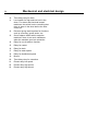
Contents
Introduction ........................................................................................... 1
Technical data ...................................................................................... 2
Installation ............................................................................................. 5
Electro-Lube Dispenser ........................................................................ 12
Safety rules ........................................................................................... 15
Mechanical and electrical design .......................................................... 16
Card programming ................................................................................ 33
Procedure ............................................................................................. 40
Maintenance ......................................................................................... 44
Trouble-shooting ................................................................................... 45
The manufacturer reserves the right to make changes to design and material
specifications.
Safety instructions
•
The machine is designed for water washing only.
•
The machine must not be used by children.
•
All installation operations are to be carried out by qualified
personnel. Licensed personnel are necessary for all electric
power wiring.
•
The interlock of the door must be checked daily for proper
operation and must not be bypassed.
•
All seepage in the system, due to faulty gaskets etc., must be
repaired immediately.
•
All service personnel must be fully faimliar with the operating
manual before attempting any repair or maintenance of the
machine.
•
The machine must not be sprayed with water, otherwise short
circuiting may occur.
•
Fabric softeners with volatile or inflammable fluids are not to be
used in the machine.
49
Introduction
1
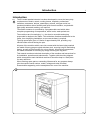
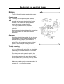
Introduction
The EX model washer/extractor has been developed to cover the heavy duty
requirements of hotels, motels, nursing homes, hospitals, professional
laundries, restaurants, airlines, steamships, schools, colleges and all onpremises laundries where flexibility and quick formula variation, coupled with
high quality automatic washing, are required.
Fig.
1
The washer extractor is controlled by a programmable card which allow
complete programming of temperatures, water levels, wash periods etc.
The machines are free-swinging, i.e., the drum is moveable and spring
suspended in relation to the frame. This minimizes vibrations transferred to the
frame, thus simplifying installation, as no concrete base is required.
The high speed spin gives a G factor of approximately 300, providing very
efficient water removal during the spin.
All parts of the machine which come into contact with the items being washed
are made of heavy gauge surgical stainless steel, ensuring long life and lasting
beauty, as well as full protection for no-iron fabrics. All electrical components
are made accessible for servicing by simply removing the top panel.
This manual contains a technical description of the machine and instructions for
its installation, operation and maintenance. Together with the wiring diagram
which accompanies each individual machine it should be kept in a safe place
for easy reference.
When ordering spare parts or contacting Wascomat for any purpose always
give the machine serial number, model, voltage and other electrical
characteristics appearing on the nameplate at the rear of the machine.
1
0655
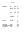
Technical data
2
EX 12
Dry load capacity
up to
13,5 kg
30 lbs
Overall dimensions
Width
Depth
Height
Net weight
Dyn.weight
870 mm
900 mm
1302 mm
290 kg
34 1/4'’
35 15/16'’
51 1/4'’
639 lbs
120 lbs./sqft
Crated dimensions
Volume
Weight
1.25 m3
315 kg
44 cu.ft
695 lbs
Inner drum
Diameter
Depth
Volume
620 mm
412 mm
120 litre
24 7/16'’
16 5/16'’
4.4 cu.ft
Speed of rotation
Wash
Distribution
Low extract
High extract
48 r.p.m.
75 r.p.m
475 r.p.m.
950 r.p.m.
G-factor
During wash
During high extract
0.8
310
Motor speed
During wash
During high extract
360 r.p.m.
3200 r.p.m.
Voltage requirements
Choice:
208-240 V 3-Phase 60 Hz
440 V 3-Phase 60 Hz
Rated power
Motor, wash
Motor, extraction
250 W
0.35 HP
1800 W
2.5 HP
Overcurrent protection
Three.-phase
15 A
Water connections
Water pressure, max
10 kp/cm2
142 psi
Recommended water pressure
2-6 kp/cm2
25-85 psi
Hose connection, water
20 mm
3/4'’
Hose connection, drain
75 mm
3'’
Technical data
3
EX 22
Dry load capacity
up to
22.5 kg
50 lbs
Overall dimensions
Width
Depth
Height
Net weight
Dyn.weight
1000 mm
1102 mm
1412 mm
553 kg
39 3/8'’
43 3/8'’
55 9/16'’
1218 lbs
157 lbs./sqft
Crated Dimensions
Volume
Weight
2.05 m3
588 kg
72.3 cu.ft
1295 lbs
Inner drum
Diameter
Depth
Volume
750 mm
500 mm
220 litre
29 1/2'’
19 11/16'’
7.8 cu.ft
Speed of rotation
Wash
Distribution
Low Extract
High Extract
45 r.p.m.
67 r.p.m.
425 r.p.m.
850 r.p.m.
G-factor
During wash
During High Extract
0.8
300
Motor speed
During wash
During High Extract
540 r.p.m.
3200 r.p.m.
Voltage requirements
Choice:
208-240 V 3-Phase 60 Hz
440 V 3-Phase 60 Hz
Rated power
Motor, wash
410 W
0.55 HP
Motor, extraction
2600 W
3.5 HP
Overcurrent protection
Three-phase
20 A
Water connections
Water pressure, max
10 kp/cm2
142 psi
Recommended water pressure
2-6 kp/cm2
25-85 psi
Hose connection, water
20 mm
3/4'’
Hose connection, drain
75 mm
3'’
Technical data
4
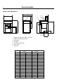
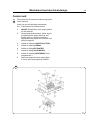
Outline and dimensions
C
A
D
E
6
1
K
L
4 3 2
M
P
B
N
O
G F
Q
7
5
1
2
3
4
5
6
7
Opening for electrical cable connection
Steam connection (optional)
Cold water
Hot water
Hot water (only EX22)
Drain outlet
Soap box
EX12
mm
inches
A
B
C
D
E
F
G
H
J
K
L
M
N
O
P
Q
R
870
1302
913
792
121
625
570
480
1100
–
240
120
1200
1110
85
203
433
34 1/4
51 1/4
36
31 3/16
4 3/4
24 5/8
22 1/2
18 15/16
43 5/16
–
9 1/2
4 3/4
47 1/4
43 11/16
3 11/32
8
17
R
2664
EX 22
mm
inches
1000
1412
1102
906
196
630
560
610
1210
320
240
120
1310
1220
85
203
498
39 3/8
55 9/16
43 3/8
35 3/32
7 3/4
24 13/16
22
24
47 5/8
12 5/8
9 1/2
4 3/4
51 9/16
48
3 11/32
8
19 5/8
Installation
Installation
5
2
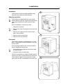
The machine is delivered with expansion bolts
and other items packed inside the drum.
Shipping securities
Fig.
2
The machine is shipped with four large metal
bracket bolted to the four suspension legs as well
as a support between the pulley and the back
plate.
Prior to installation, follow these steps:
• Unpack the machine.
Fig.
3
• Remove the lower front panel and the two rear
panels.
• Remove the support from the pulley at the
back of the machine.
• Remove both front brackets.
1247
3
• Remove both rear brackets.
Placement
The machine should be installed close to a floor
drain or open drain to make installation, use and
service easier.
The following clearances are recommended for
ease of installation and service:
Fig.
4
• At least 20 inches between the machine and
the wall behind it.
• At least 2 inches on each side.
The floor must be able to support a static load of
790 lbs for the EX-12 and 1440 lbs for the EX-22.
The maximum impact load at extraction is 260
lbs force for the EX-12 and 480 lbs for the EX-22.
1248
4
1249
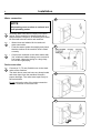
Installation
• Mark and drill two holes 3/8'' in (8 mm) in
diameter and approximately 3 1/2'' in. (90 mm)
deep according to the dimensions in figure 5.
EX12
866 mm
34 3/32 in.
7
• Insert into the holes the expansion bolts
supplied with the machine. Fit the washers
and nuts.
33 mm
1 5/16 in.
780 mm
30 23/32 in. 43 mm
1 11/16 in.
EX22
996 mm
39 7/32 in.
It is of utmost importance that the machine
is level, from side-to-side as well as frontto-rear. If the machine is not properly
levelled, it may result in out-of-balance
cutout without a real out-of-balance in the
drum.
910 mm
32 11/16 in.
Fig.
830 mm
6
• Check that the machine is level and steady.
Use stainless or galvanized washers between
the machine and the floor.
896 mm
Fig.
782 mm
• Place the machine in position. Never lift the
machine by the door or handle.
30 25/32 in.
5
35 9/32 in.
Fig.
5
28 3/16 in.
Mechanical installation
716 mm
6
33 mm
1 5/16 in.
35 13/16 in. 43 mm
1 11/16 in.
1250
6
0620
7
0621
Installation
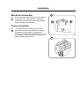
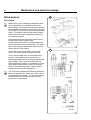
Electrical installation
Fig.
8
7
8
Although the machines are fitted with thermal
overload in the motor windings and separate fuse
for the control circuit, a separate three-phase
circuit breaker must be installed for all threephase machines.
For proper overcurrent protection, check the data
plate at the rear of the machine. Also consult
local electrical code for special requirements.
Fig.
8
Connect L1, L2, L3 and ground wires according
to the markings of the terminal block. The cable
is to hang in a large loose loop, supported by the
clip of the terminal block.
To ensure proper operation the drum must
rotate counter-clockwise (seen from the front)
during extraction. If the drum rotates in the wrong
direction interchange line L1 and L3 at the power
connection terminal.
Fig.
9
0622
9
Check the incoming power for a high voltage leg.
If present, connect that line to L2 on the terminal
block.
0624
Installation
8
Water connection
10
NOTE
All plumbing must conform to national and
local plumbing codes.
Fig.
10
Fig.
11
Incoming water lines do not require non-return
valves, as the machine is already fitted with a
siphon breaker. However, all incoming lines must
be fitted with shut-off valves and strainers.
• Water inlets are labelled for hot and cold
water connection.
• Flush the water system thoroughly and check
that the strainer at the machine inlet is fitted
correctly.
Fig.
12
1252
11
• Connect the machine to the water mains with
3/4'’ reinforced rubber hosing not to exceed 6
ft in length. Hang the hosing in a large loop.
Do not use rigid piping.
Drain connection
Fig.
13
Connect a 3'’ (75 mm) flexible hose to the drain
outlet of the machine.
The drain house must not have any sharp bends
and must slope from the machine to assure
proper drainage. The outlet must open freely to
the main drains.
0626
12
Do not reduce the size of the drain connection
from the machine to the waste line.
1641
13
1628
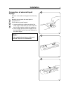
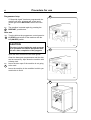
Installation
Connection of external liquid
supply
9
14
Remove cover and cover support over the soap
box.
Fig.
14
Fig.
15
Fig.
16
Bend all the way back the metal plate in
compartment 3.
Pull the knobs up and forward.
1. Loosen both knobs so that one side of the
metal fingers underneath can slide under the
top lid of the machine, within the supply box.
2. Fit the supply injector into the supply box so
that both sides are held securely in places by
the metal fingers.
1336
Note:
15
If the supply injector does not fit turn it
around. You have it in backwards.
1334
16
1333
Installation
10
Fig.
17
1. Drop the knob into the larger opening in the
supply injector lid.
17
2. Tighten securely. Do not overtighten! Do not
use pliers or other tools to tighten the knobs!
Fig.
18
1. Stretch the multi-rubber ring B and select the
correct size ring which will fit snuggly on the
chemical tube you are using. Ring A is used
for tubes with Ø 1/3" (8 mm).
2. Use scissors or a razor to carefully cut out the
proper size rubber ring. Wrap the rubber ring
around each tube after threading each tube
trough the plastic nipple. Run the tube trough
the compression nut to the bottom of the
compartment. Cut the end of the tube at an
angle. Hand tighten the plastic nipple on to the
compression nut.
1332
18
1331
18
1331
Installation
Electrical connection
Fig.
19
11
19
At the rear side of the control unit are two quick
connectors. When the machine is delivered
connector A is connected. When using powder
supply, change to connector B.
Pump connection
Fig.
20
To the right of the incoming power terminal
connection block is the connection for pumps.
Depending on the number of pumps to be
connected, they shall be connected from 1-5 and
C (common) on resp. connection. The pumps
obtain signals from the timer.
1932
20
1612
Electro-Lube Dispenser
12
Instruction for setting timing on
electro-lube oil dispensing
Fig.
21
Fig.
22
Fig.
23
21
Pry off the switch panel cap with a screwdriver.
• Under the cap are the switches for time
setting.
• Set the "Light" and "12M" dip switches to the
"On" position. Make certain all other switches
are in "Off" position.
• The light will start flashing after a few minutes
and will continue to flash every 15th to 20th
seconds as long as the dispencer is in
operation.
Fig.
24
• The decal shown below should be affixed at
the front of the machine and updated as
required.
2207
22
2208
24
23
IMPORTANT
NOTICE
This machine is equipped with an automatic oiler,
located at the right rear of the machine, which keeps
it lubricated for long bearing and seal life.
The amount of oil in the container is sufficient for
approximately one year's lubrication. It is of utmost
importance that the oiler does not become empty.
Therefore we recommend that the rear panel to be
removed and a visual inspection to be made on a
bimonthly basis. When the oil reaches a low level,
the cannister must be replaced with a new one
available from Wascomat as Part No. 827601.
Date Last Replaced
1M
2M
3M
O
F
F
6M
12M
B
Date Last Replaced
ON
LIGHT
2733
Installation
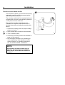
Start-up and safety checklist
13
25
Before initial start-up of a Wascomat washerextractor, the following safety checks must be
performed:
Fig.
25
• Make sure that all electrical and plumbing
connections have been made in accordance
with applicable local codes.
• Use only flexible water fill and drain hoses of
the proper length to avoid sags and kinks.
• Make sure the machine is properly grounded
electrically.
Before the machine is operated, the door safety
interlock must be checked for proper operation
as follows:
Fig.
26
Fig.
27
• When washer loading door is open, the
machine must not start. Verify this by
attempting to start washer with door open.
1637
26
• When washer is in operation, the loading door
is locked and cannot be opened. Verify this by
attempting to open the loading door when the
machine is operating. If necessary, consult
this manual for proper operation of the door
lock and door safety interlock or call a
qualified serviceman.
IMPORTANT:
Door safety interlock must be checked
daily in accordance with above procedure.
1675
WARNING:
Before servicing Wascomat equipment,
disconnect electrical power.
27
1615
Installation
14
Function control check-out list
28
In the machine cylinder, you will find the warranty
registration card, a copy of the warranty policy
and other pertinent material.
The warranty card should be completed and sent
to Wascomat. All other items should be placed in
a safe place for future reference.
The machine should be cleaned when the
installation is completed, and checked out as
detailed below without loading the machine with
fabrics:
1. Check the incoming power for proper voltage,
phase and cycles.
Fig.
28
2. Open manual shut-off valves to the machine.
3. Turn on electric power.
4. Check the door safety interlock as detailed on
page 9 of this manual.
5. Run through a complete cycle, checking for
water temperature, drain operation and the
extract function. For operating instructions,
see the section marked ’’Procedure’’.
NOTE
All machines are factory tested prior to
shipment. Occasionally, some residual
water may be found when the machine is
installed.
1640
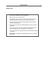
Safety Rules
Safety rules
• This machine is designed for water washing only.
• Machines must not be used by children.
• All installation operations are to be carried out by qualified personnel.
Licensed personnel are necessary for all electric power wiring.
• The interlock of the door must be checked daily for proper operation
and must not be bypassed.
• All seepage in the system, due to faulty gaskets etc., must be repaired
immediately.
• All service personnel must be fully familiar with the operating manual
before attempting any repair or maintenance of the machine.
• This machine must not be sprayed with water, otherwise short circuiting
may occur.
• Fabric softeners with volatile or inflammable fluids are not to be used in
this machine.
15
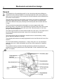
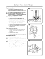
Mechanical and electrical design
16
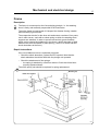
General
Fig.
29
This machine is a free-swinging model i.e. the outer drum and motor bridge are
suspended in the machine chassis via a spring suspension with a strong spring in
each corner of the machine. Each spring has a shock absorber which dampens the
movement of the machine.
The inner drum is driven by two motors via a V-belt: one motor for washing and
distribution speed and one for extract speed. The inner drum is mounted in the
outer drum with two heavy duty bearings at the back plate and is sealed with two
V-rings.
The two motors are suspended underneath on a motor support with a belt
tensioning device. The motors are mechanically coupled to each other with V-belts.
During wash and distribution speed the spin motor transmits power to the drum,
through a clutch arrangement.
The water inlet and drain are both situated under the outer drum. This improves the
flow during filling and prevents water vapour from entering the detergent
compartment.
The robust square door is locked with a handle which is interlocked by a safety
device when the machine is running.
The manual push buttons and card programmed control are fitted at the front of the
machine.
All control and indicating components i.e. relays, delay unit, etc. are assembled
under the top cover, easily accessible from the top of the machine for simplified
servicing.
The machine housing consists of hot-dip galvanised, painted steel plates and
stainless steel sheets, painted on the front and sides. It has a stainless door (and
front, on request).
29
Operating
instruction panel
Wash and distribution
motor
Extract motor
1617
Mechanical and electrical design
17
Frame
Description
Fig.
30
The frame is constructed on the free-swinging principle, i.e. the washing
drum is freely and resiliently suspended in the fixed frame.
The entire frame is constructed of U-shaped iron beams forming a stable
and torsionally rigid structure.
The suspension device for the drum unit and motors consists of four posts,
one in each corner, each with a robust spring to which the washing drum
supports are attached. In order to prevent excessively great vibrations
which can be caused by imbalance in the drum, a shock absorber is fitted
between the drum and frame by each spring. (The EX-12 model has twin
shock absorbers at the front.)
Repair instructions
If the out-of-balance cutout is repeatedly triggered
• Check the shock absorbers, replace them if required. Note that the
shock absorbers should be fitted with the plunger rod upwards.
• Check the attachment of the springs:
- the spring is attached by a bolt from above: Check that it has been
properly tightened down.
The entire spring unit should be replaced in spring replacement.
30
1618
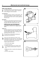
Mechanical and electrical design
18
Drum with bearings
Description
Fig.
31
The inner drum is journalled to the outer drum by two robust bearings in a
bearing housing which is bolted to the rear plate. The bearing unit supports the
drum without any support being needed at the front. Shaft seals of the V-type, as
well as O-rings, seal against leakage.
The space between the bearings is packed with grease during assembly. No
additional grease is required.
The inner drum shaft is continuous, and the V-belt pulley is attached to the
protruding journal by an adapter sleeve.
The outer drum end plate consists of two parts, the inner and outer end plates
which are bolted to the bearing housing with through bolts. NOTE: The inner and
outer end plates must not be taken apart when the bearings are replaced.
The outer drum and rear plate are held together by 3 straps.
The outer drum is connected to its resilient suspension by four supports, bolted to
the end plates. It is important that these supports are not loosened from the rear
plate during repairs.
31
EX 12
0635
Mechanical and electrical design
Safety locking device
19
32
Description
Fig.
32
The machine safety locking device includes a
safety interlock system which prevents personal
injury through the following precautions:
• The machine cannot be started until the door
is shut.
• The door is automatically locked when the
machine starts.
• It is not possible to open the door until 2-3
minutes have elapsed after the washing
program has ended. This ensures that the
drum is motionless when the door is opened.
Repair instructions
It the coil does not lock the door:
• Check that the coil is receiving 100-110 V DC.
Measure the coil to determine if there is an
interruption.
• Check that the armature of the coil is not
stuck.
• If necessary, replace the entire coil.
Other possible faults:
-
Faulty microswitch.
Faulty delay circuit.
Moving parts jammed.
Handle not in locking position.
Door lock solenid
Y80
1676
Mechanical and electrical design
20
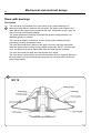
Function
If the machine has not been energised within the last three minutes, the door will remain
unlocked. When the machine is energised the door will be locked if a program is activated or
if the drum is rotating. Upon completion of a program the door will be unlocked automatically
as soon as the drum has stopped rotating.
If the power supply is cut to a machine which was energised the door will remain locked for
three minutes, after which time it will be unlocked automatically.
Fig.
33
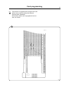
The diagram below shows how the delay unit works.
When the machine is energised the delay unit is fed phase and neutral on X194:5 and
X194:4 respectively. The door lock coil Y80 is then fed phase (via a normally closed relay
contact) and neutral from X194:3. The relay coil acts on two conditions – that the drum is at a
standstill and an "open" signal from the programmer circuit board:
• One side of the relay coil receives a zero potential signal when the rotation guard shortcircuits X193:1 and 2.
• The other side of the relay coil is supplied with phase from the programmer circuit board
("open" signal).
Both of these conditions must be fulfilled for the door to be unlocked.
In the event of a power cut the capacitor will discharge via the relay and the door lock
solenoid. In this way the door lock solenoid continues to operate for three minutes, after
which the door is unlocked automatically.
33
Fördröjningsenhet
D1
Delay unit D1
X194:5
X194:4
X194:3
X194:2
X194:1
X193:2
X193:1
Voltage
Spännings
matning
feed
Rotation guard
"Open" signal
LucklåsRotationsDoor
lock Signal "öppna"
from
programmer vakt
programspole Y80 från
coil Y80
verkskort
circuit board
2439
Mechanical and electrical design
Fault location
Door does not unlock
Conditions: wash program ended and drum at a standstill.
Measure the voltage between the following points:
1. X93:2 - X93:3 Should be 0 V DC. If the voltage is 220 V AC, check the rotation guard.
2. X193:1 - X193:2 Should be 0 V DC. If the voltage is 220 V AC, check the rotation guard
and the cables between rotation guard and delay unit.
3. X194:1 - X194:4 Should be 220 V AC. If not, the "open" signal from the programmer
circuit board is absent. Check pcb and cables between pcb and delay unit.
If the door is still locked, replace the delay unit.
Door does not lock
Conditions: door closed and wash program activated.
Measure the voltage between the following points.
1. X194:1 - X194:4 Should be 0 V AC. If the voltage is 220 V AC, the programmer circuit
board will constantly send the "open" signal. Check pcb and cables between pcb and
delay unit.
2. X194:2 - X194:3 Should be 200 V DC.
– If there is no voltage, replace the delay unit.
– If this voltage is present, check the door lock coil and its cables.
21
Mechanical and electrical design
22
Rotation guard
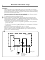
Description
The rotation guard checks that the machine is completely at a standstill before the door can
be opened. When the drum has been at a standstill for approx. two seconds the solenoid in
the door lock is deactivated and the lock can be opened (provided that the machine has been
emptied of water and the programmer has reset). The rotation guard also checks that the
drum is revolving when the wash or extraction relays are operating.
Fig.
34
The rotation guard consists of a circuit board in the automatic control unit and a sensor in a
holder on the machine rear. There is a magnet on two of the spokes of the pulley. Each time
a magnet passes the sensor, a contact closes inside the sensor and it relays a pulse to the
rotation guard.
When the machine is at a standstill the rotation guard relays K1 and K2 are closed, which
means that the delay unit and the HI-TEK receive confirmation that the drum is not moving,
i.e. the rotation guard and the HI-TEK allow door opening.
34
X90 LED
X95 X96
X99
X193:2
X193:1
Fuse F1
2019
X91
X92
X93
X94
X93:2
X95:1
X95:2
Logic section
Pulses from B41: K1 and K2 change
immediately.
No pulses from B41: K1 and K2 operate after
approx. 2 sec.
This circuit is not used in HI-TEK
X90:1
X93:3
X90:2
L1
X91:1
N
X91:2
To control
circuits
X92:2 X92:3
X72:7
X72:4
2436
Mechanical and electrical design
23
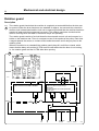
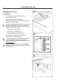
Control unit
Fig.
35
The control unit is mounted under the top panel
in the machine.
In the unit are the following components:
2-8
Push buttons for manual control.
2
ON/OFF Push button, main supply switch
for the machine.
3
Restart push-button switch. When stop is
programmed the switch lights up and
buzzer goes on. When the switch is
depressed the program will continue from
where it stopped.
4
Switch for selecting GENTLE ACTION.
5
Switch for opening DRAIN.
6
Switch for filling HOT WATER.
7
Switch for filling COLD WATER.
8
Switch for flushing DETERGENT from
compartment 1.
9
Delay unit keeps the door locked appr.
2-3 min. after the program is finished.
35
1658
Mechanical and electrical design
24
10
Time delay relay for drain.
11
Level switch for high and low level in the
drum. For steam and electrical heated
machines, the switch is also controlling that
there is water in the drum before the heat
comes on.
12
Reverser giving start impulses for functions
such as reversing, gentle action, etc.
13
Out of balance switch which stops the
machine if there is too much unbalance
when the machine goes into extraction.
14
Relay for out-of-balance function.
15
Relay for restart.
16
Relay for drain.
17
Relay for wash speed.
18
Relay for distribution speed.
19
Buzzer
20
Time delay relay for extraction.
21
Extract relay low speed.
22
Extract relay high speed.
23
Extract relay high speed.
Mechanical and electrical design
Relays
25
36
The EX 12 and 22 models employ eight relays.
Construction
Fig.
36
The body of the relay holding the stationary
contacts is made of current-resistant plastic. A
solenoid and a contact bank hold the moving
contacts. The contacts are spring-loaded to
assure the correct contact pressure.
The relay is constructed for continuous
operation, whether mounted horizontally or
vertically.
Screw-type terminals provide perfect connections
even when one or two wires have different
diameters.
Operation
When the solenoid is energized, the two halves
of the magnet core are drawn together, pulling
down the moving contacts, thus making or
breaking the circuit. When the current cuts out,
springs force the contact bank into its original
position, thus closing or opening the circuits.
Trouble shooting
If the relay fails to operate despite power to the
coil, turn off the power and check the solenoid by
measuring the resistance across the terminals
(1).
If the relay hums when power is applied, this
indicates either a break in the insulator holding
the moving contacts at the axle where it holds
the top half of core (3) or a rusty core (4), which
can be cleaned.
Make sure that the moving contact assembly (4)
moves freely. Always replace burnt or pitted
contacts (2)... do not reuse contacts.
0301
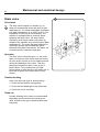
Mechanical and electrical design
26
Drive motors
37
Description
Fig.
37
Both motors, one for wash and distribution and
one for extraction, are installed on the same
motor bridge. The motors drive the drum and are
mechanically connected to each other by V-belts.
On the EX 22 there is also an electromechanical
clutch. The motors rotate at each others' speed
during the wash speed, distribution speed and
low extraction speed.
During high extraction speed the speed control
on the EX 22 gives a signal to the
electromechanical clutch. This disconnects the
motors from each other mechanically. The wash
motor now rotates at distribution speed and the
extract motor at high speed.
On the EX 12 the power supply to the wash
motor is disconnected by the speed control.
0638
38
On the motor bridge there are belt tensioning
devices. The extract motor is screwed to a
mobile plate which moves via oblong holes in the
motor bridge. This is used to tension the belt
drive between the motors. It is possible to tilt the
entire motor bridge with the use of the oblong
holes on the wash motor side. This is used to
tension the V-belt up the wash drum.
Fig.
38
The motors are equipped with thermal protectors
which are placed in the stator coil. In the case of
overheating in the motors, i.e. if the temperature
exceeds 130°, the protector contacts cut the
power to the motor relays.
0639
Mechanical and electrical design
Repair instructions
27
39
Overheated motor, motor not running
• Wait till motor has cooled down. Motor thermal
protectors are automatically reset after appr.
30 minutes. Restart.
• Possible cause of motor protector releasing
repeatedly could be oversensitivity of thermal
protector.
Very noisy motor
• Breakdown of bearings - replace bearings or
motor.
180 lbs force
Motor running slowly
• The motor is probably running on two phases
- measure coils on terminal.
1/4 in.
Wash motor only runs at one of the speeds
• Check that the quick connection is correctly
connected.
• Measure coils at connector, as the fault can
be caused by interruption in one of the coils.
Motor locks
5/16 in.
92 lbs. force
• Breakdown of bearings - replace bearing or
motor.
Motor does not turn
• Check belt tension.
Tensioning of the V-belt
Fig.
39
• Belt between the wash motor and extract
motor
- release and adjust backing plate to correct
belt tension according to illustration. Fasten
plate.
• Belt between extract motor and drum
- remove screws for the attachment of motor
bridge at extract motor side, lower motor
bridge to correct belt tension according to
illustration and fasten bridge.
0640
Mechanical and electrical design
28
Supply injection valve
40
Construction
Fig.
40
This valve has a single-inlet with three outlets,
each with its own solenoid coil.
The body is made of heat-resistant polyamid
plastic and the solenoids encased in water-tight
plastic. The electrical connector terminals are
spade lugs.
A filter screen on the inlet side prevents dirt from
entering the valve. Flow restrictors can be placed
at either the inlet or any of the outlets.
Operation
Fig.
41
When the solenoid is energized, the springloaded plunger is drawn up and the pilot valve in
the center of the diaphragm open. Because of
the difference in diameter between the pilot valve
opening and the ventilating hole in the
diaphragm, the pressure above the diaphragm
drops to a point where the admission pressure
below the diaphragm can lift the diaphragm, thus
opening the valve.
0306
41
When the current to the solenoid is cut off, the
plunger spring will press the plunger against the
pilot opening of the diaphragm. The pressure
above the diaphragm then rises to correspond to
the water inlet pressure and the pressure of the
spring will close the valve.
0307
Mechanical and electrical design
Repair instructions
29
42
Limescale can block the hole in the valve
diaphragm and interfere with the function of the
valve.
Fig.
42
It is therefore advisable to dismantle and clean
the valve at certain regular intervals. The
frequency depends on operating conditions and
the level of contamination in the water.
If the valve does not open
• Check that power is supplied to the coil.
• Check the coil with an instrument to determine
whether there is a break or a short circuit.
• Dismantle the valve (see below) and check
the openings in the valve diaphragm.
• Check the inlet strainer and clean as required.
0308
43
• Undo the coil and clean the surfaces of the
magnetic core.
If the valve does not close
• Check that the coil is not live. The valve is
normally closed when the magnet is not
energised.
• Check the return spring.
• Check the diaphragm (pilot pressure opening).
Dismantling the valve.
Fig.
43
Fig.
44
• Pull the coil stright upwards. Use a
screwdriver if necessary to carefully undo the
coil.
• Use the tool supplied (attached to one of the
hoses when the machine is delivered) to open
the valve housing. Slide the tool over the
protruding plastic sleeve to that the pegs on
the tool engage the corresponding sockets in
the valve housing.
0309
44
• Use a spanner or a pair of pliers and unscrew
the upper part of the valve housing.
0310
Mechanical and electrical design
30
Inlet valve EX 22
Fig.
45
45
The water inlets have brass bodies with a larger
cross section of the outlet in order to acheive a
shorter filling time for the machine.
Construction
The valve housing is made of pressed brass. The
spring-loaded plunger is made of stainless steel
and located at its lower end is a rubber gasket for
the pilot valve.
Operation
The valve is automatically operated by means of
a rubber diaphragm and a pilot valve in exactly
the same way as the supply injector valve.
NOTE: To strip, clean, re-assemble and
troubleshoot the inlet valve, follow the
instructions outlined for the supply injector
valve.
0311
46
Clean out
At water temperatures of more than 60°C/140°F,
the lime deposits are heavily increased. This can
cause function problems due to blocking up the
equalizing orifice of the valve.
Fig.
45
Fig.
46
The fault can be eliminated by cleaning the
equalizing orifice (marked A).
If there are much deposits the orifice can be
changed from 0.5 mm to 0.8 mm. The screwhead
of the orifice is marked with 1 ring for the size of
0.5 mm and 2 rings for the size of 0.8 mm.
Clean the orifice as follows:
0368
47
1. Shut off the main supply.
2. Unscrew the orifice
Fig.
47
3. Clean the hole in the orifice carefully with a
pin or similar not thicker than 0.5 resp. 0.8
mm.
4. Mount the orifice, be careful with sealing and
tighten.
5. Open the main supply.
0369
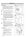
Mechanical and electrical design
31
Soap supply box
Fig.
48
The three-compartment soap supply box is located at the top of the machine. Viewed
from the front, the compartments are marked with figures 1, 2 and 3.
Compartment 1 and 2 are used for adding detergent directly to the wash.
Compartment 3 is used for adding fabric softener. All three compartments can be
programmed individually.
48
0312
Mechanical and electrical design
32
Drain valve
49
Description
Fig.
49
The drain valve consists of a bracket (1), on
which are mounted the motor and gear (2) and
diaphragm (3). The rubber diaphragm is resistant
to a water temperature up to 100°C (212•F). The
installation of a lint trap is not necessary. The
machine is equipped with an overflow, which
bypasses the drain valve. The drain can be
cleaned by removing the drain connection (4)
outside of the machine or by removing the rubber
diaphragm (3). The motor and gear assembly is
covered by a plate and provided with quickdisconnect electrical connections. The stator coil
is constructed for continuous operation.
Operation
The drain valve is normally open, i.e. the motor
does not close the valve until it receives current.
As soon as the current is cut, the shaft turns and
opens the diaphragm of the valve. This also
permits the machine to drain, in the event of
power failure. The overflow hose (5) leads
excess water or suds directly to the waste line, in
the event of failure in the inlet valves or level
control.
Trouble-shooting
If the valve does not open or close properly:
1. Check that the shaft is moving freely.
2. Check that the diaphragm is not obstructed.
3. Check the coil for continuity.
Clean out
Periodic cleaning of the valve is recommended,
depending upon how often the machines are
used, as well as the type of wash handled most
frequently.
0313
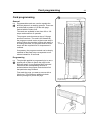
Card programming
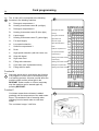
Card programming
33
50
Step no.
General
Fig.
50
Programmable cards are used to regulate the
different phases in a washing process. These are
provided with a pattern of 16 ribs with pegs
marked with the letters A-Q.
The cards are available in two sizes: 80 or 120
steps numbered from 0 upwards.
The program controls sense a step of 16 pegs
across at one time. The card is fed forward by
the program controls motor so that a new step is
sensed. When the machine is filling with water or
is heating the water, the program controls motor
stops until the required level or temperature is
reached.
80 or
120 steps
If necessary, the program controls can be simply
modified so that each step corresponds to one
minute instead for 30 seconds.
Programming
Fig.
51
The principle applied to programming is to use a
special pair of pliers to punch the pegs in the
different stages. A peg that has been removed
means that the corresponding function is
activated when the program controls have fed
that particular stage forward.
First mark the pegs you want to remove with a
felt tip pen. Then make an additional check
before you begin to punch the pegs.
Step number (in relation to the edge of the
programcontrols)
0340
51
0341
Card programming
34
Fig.
52
The 16 ribs (A-Q) correspond to the following
functions in the washing machine:
52
A-
Detergent compartment 1
B-
Heating, thermostat control B (red light)
C-
Detergent compartment 2
D-
Heating, thermostat control D (blue light)
E-
Liquid supply
F-
Heating, thermostat control F (yellow light)
High water level
G-
For liquid supply
Stop with signal
H-
Low speed extraction
High speed extraction
I-
Softener compartment 3
Drain
K-
Drain
Softener compartment 3
L-
High speed extraction (with rib H also cut)
M-
Stop with signal
N-
High water level
O-
Filling with cold water
Heating, thermostat control D
P-
Cool down (see explanation below)
Detergent compartmnet 2
Q-
Filling with hot water
Heating, thermostat control B
Filling with hot water
Cooling
Filling with cold water
Low speed extraction
Liquid supply 4
Heating, thermostat control F
Liquid supply
Function M
Fig.
53
Stop with signal can be used as the last function
in a program or in the event of a temporary stop
in a washing process. A buzzer sounds when the
machine stops and the yellow light in the
RESTART button comes on. After a temporary
stop the machine can be started again by
pressing RESTART.
0342
Function P
Cool down means that cold water is added
gradually until the temperature of the wash water
drops. This avoids the risk of creasing when
changing from hot wash water to cold rinse
water.
53
The cool down is appr. 3-4°C/min.
0663
Card programming
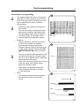
Instructions for programming
Fig.
54
35
54
• The program begins with step 0. Program the
step before 0 in the same way as 0 to ensure
a correct program start even though the card
may be pushed too far into the controls.
• Program times
Fig.
55
- Each step in the program corresponds to
30 seconds.
- The time for heating and filling with water
shall not be included in the program time.
This also applies when water is added for
cool down (rib P). The program control
motor is stationary during these phases.
• Extraction
0343
- After the extraction has been in progress
for about 70 seconds, the machine
automatically changes to low speed
extraction and then after 60 seconds go up
to high speed extraction unless the LOW
SPEED EXTRACTION switch is pressed
in.
Fig.
56
- The drum should be filled with water to high
level before draining and extraction starts.
This is to ensure that the wash is effectively
distributed around the drum.
55
30 sec.
- Drain (rib D) must be programmed to last at
least one minute (two program steps)
before the extraction starts.
- Drain shall be programmed during the
entire extraction time and for at least
2,5 min afterward.
• Drain
0344
56
- The machine always operates at distribution speed when drain is in operation
(rib K).
High level
Drain
< 1 min
Extraction
0345
Card programming
36
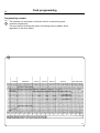
Programming example
Fig.
57
The following is a description of how the card for normal soiled goods
would be programmed.
The time required for filling with water and heating must be added, where
applicable, to the times stated.
57
Prewash
Mainwash
Rinse 1
Rinse 2
Rinse 3
Rinse 4
Stop with signal
1244
Card programming
Pre-wash
Time: 4 minutes (steps 0-7)
The prewash comprises two phases:
1 Filling and prewash (steps 0-6)
Cold water is added (rib O) until high water level is reached (rib N) and
is activated during the whole prewash cycle. This adjusts the level
automatically while the program is in progress.
2 Draining (step 7)
The drain valve opens (rib K).
Main wash
Time 9 minutes (steps 8-25).
The main wash comprises three phases:
1 Filling with water and detergent (step 8).
Hot and cold water are added (ribs O and Q). The detergent is flushed
down
(rib C).
2 Washing (steps 9-24)
Heating to the temperature set by the thermostat marked D (rib D).
Filling with hot and cold water (ribs Q and O) and heating (rib D) are
activated during the entire wash sequence. This controls the level and
temperature automatically while the wash cycle is in progress.
3 Draining (step 25)
The drain valve opens (rib K).
37
Card programming
38
Rinse cycle 1-3
These three rinse cycles are identical.
Time: 4 minutes and 30 seconds (steps 26-34, 35-43, 44-52).
Each rinse cycle comprises three phases:
1 Filling with water and rinsing (steps 26-31, 35-40, 44-49).
Filling with cold water (rib O) to high water level (rib N).
2 Draining (steps 32-34. 41-43, 50-52)
The drain valve opens (rib K).
3 Spin (steps 33-34, 42-43, 51-52).
Spin (rib H and rib L).
Note that the drain valve (rib K) and high level (rib N) are activated
during the extraction.
Rinse cycle 4
Time: 9 minutes (steps 53-70).
This rinse cycle comprises four phases:
1 Filling with water and fabric conditioner (step 53).
Filling with cold water (rib O) to high water level (rib N). Fabric
conditioner is flushed down (rib I).
2 Rinse (steps 54-58)
Filling with cold water (rib O) and high water level (rib N) are activated
during the entire rinse sequence. This controls the level automatically
while the rinse cycle is in progress.
3 Drain (steps 59-70)
The drain valve opens (rib K).
4 Extraction (steps 59-70).
Extraction (ribs H and L).
Note that the drain valve (rib K) and high level (rib N) are activated
during the extraction.
Stop (step 71)
The machine stops and the buzzer sounds (rib M).
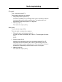
Card programming
Fig.
58
39
The machine is supplied with a function test card
which can be used for testing the different
functions after installation.
All functions, which can be programmed on the
card, are tested.
58
1245
Procedure for use
40
Procedure for use
59
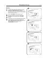
Preparations
Sort the wash according to the washing
instructions on labels.
Empty pockets and pull up zippers.
Open the machine door, insert the wash goods
and close the door again.
Fig.
59
Measure the detergent and the fabric conditioner
according to the instructions on the detergent
packet and add to the soap box according to the
program card you are using:
• pre-wash in compartment 1
• main wash in compartment 2
• fabric conditioner in compartment 3
0256
60
The machine is also fitted with separate
connections for liquid detergent.
Fig.
60
Fig.
61
For auxiliary steam or electric heated machines,
set the temperatures with the thermostat
controls. Use the control marked B (red lamp) for
manual washing.
When washing delicate fabric, press GENTLE
ACTION. This provides more gentle treatment of
the wash goods.
0330
61
0657
Procedure for use
Washing
Fig.
62
Fig.
63
Fig.
64
Fig.
65
41
62
Turn the dial on the card programmer control
panel to the 0 (STOP) position. Insert a
programmed card, with the pegs upwards, into
the opening below the control. Push the program
card in as far as it will go.
Press 1-0 (ON/OFF), push-button switch.
Start the machine by turning the dial on the
programmer control panel to the I (START)
position.
The water level can be raised while the program
is in progress by using the push-buttons for
water. Additional detergent from compartment 1
can be flushed down by pressing the
FLUSHDOWN push-button.
0658
63
0659
64
0660
65
0661
Procedure for use
42
Programmed stop
66
If ''Stop with signal'' has been programmed, the
machine will stop, a buzzer will sound and a
yellow light on the RESTART button will come
on.
Fig.
66
The machine is started again by pressing the
RESTART, push-button.
After use
Fig.
67
Turn the dial on the programmer control panel to
O (STOP) and switch off the machine with the
I-O (ON/OFF) switch.
CAUTION
The door is locked while the wash program
is in operation and cannot be opened until
2-3 min. after completion of the program.
0663
67
Open the door and remove the wash goods.
Clean the detergent compartments and the door
seal as necessary. Wipe down the machine with
a damp cloth.
Fig.
68
Leave the door open if the machine is not going
to be used.
Leave the machine in the condition in which you
would wish to find it.
0664
68
0665
Procedure for use
Manual washing
Fig.
69
43
69
Drum rotation
To produce drum rotation during manual
washing, an unprogrammed card must be
inserted in the program controls and the
programmer knob turned to I (START).
Water filling with detergent and drain
Fig.
70
Fill with water by pressing COLD WATER and/
or HOT WATER.
Use FLUSHING DOWN DETERGENT to flush
down the detergent from compartment 1
(prewash).
Water is drained from the machine with DRAIN.
Heating and extraction
0666
70
A card must be programmed to provide these
functions. Refer to the section on card
programming.
Caution
For extraction, the ''drain'' phase must be
programmed for at least 30 seconds (one
program step) before extraction takes place.
In addition, ''drain'' must be programmed
during the entire extracting time (and for 30
seconds after wards for final extraction).
0661
Maintenance
44
Maintenance
71
The carefully considered machine design means
that preventive maintenance to reduce faults has
been reduced to a minimum. The following
measures should however be carried out at
regular intervals and to the extent determined by
the amount of time the machine is used.
Daily
Fig.
71
• Clean the door seal and remove detergent
residue and check that there are no leaks.
• Clean the detergent compartments and wipe
down the machine with a damp cloth.
Fig.
72
• Check that the drain valve does not leak.
• Start the machine with the program card
inserted and check that the door remains
locked while the machine is operating. Let the
machine run for 2 minutes. Stop the machine
by turning the control on the control panel to
0. Check that the door cannot be opened until
2-3 min. after the program is completed.
1647
72
Every three months
• Check that valves, hoses and connections do
not leak.
• Remove any textile lint from the drain
opening.
Fig.
73
• Remove the cover plates of the machine and
check that the V-belt of the wash motor is
undamaged and correctly tensioned.
• Wipe and clean the inside of the machine,
making sure that the control components are
protected from moisture and dirt during the
cleaning operation.
0240
73
• Check level of oil in electro-lube oil dispenser.
Troubleshooting
If the machine does not start, check that:
• the machine's circuit breaker is on,
• the 0-1 (ON/OFF) switch is pressed on,
• the door is properly closed,
• the program card is inserted and the
programmer control dial is turned to I
(START).
• both taps on the wall are turned on.
1619
Contact your service engineer if any fault
persists.
Trouble shooting
Trouble shooting
The purpose of the trouble shooting guide is to facilitate the location and
correction of the most common machine problems.
Before the top panel is removed, power to the machine is to be switched off at
the main source or at the separate circuit breaker.
At each trouble shooting attempt, the plug in connectors of the control panel
should be moved in and out in order to eliminate improper contact due to faulty
connection.
Please note that this guide does not include all possibilities, but only those most
likely to cause the symptoms listed.
In trouble-shooting electrical problems, always make certain to have the proper
electrical schematic or wiring diagram at hand. Test for power using a V-O-M or
similar meter on the AC voltage scale. Test for continuity with all electrical power
off.
If machine does not start
A Check the circuit breaker in the power feed line to the machine.
B Check the door safety switches.
C Check the glass cartridge fuse.
D Check the normally closed auxiliary contact on the extract relay.
E Check reversing switch.
F Check the V-belt and motor.
G Check programmer switch M.
H Check the start switch on the side of the programmer.
If water does not drain
A Check the drain valve and motor and gearing for proper operation.
B Disconnect drain hose connected to drain line. If full flow of water comes out,
the problem is in the main waste line. If water flow is slow, the problem is the
accumulation of foreign materials between the drain valve and drum outlet of
machine.
C Clean valve body for any foreign objects.
D Check program switch K.
E Check the drain relay.
If machine does not extract
A Check extract relay and relay coil for proper operation.
B Check programmer switches H and/or L
C Check the extract safety level control.
D Check the reversing switch.
E Check the door lock.
F Check all the drain items of ''If water does not drain''.
45
Trouble shooting
46
If motor does not operate at wash speed
A Check wash relay.
B Check motor and V-belt.
C Check reversing mechanism.
D Review procedures outlined under Section 1 above.
If machine runs slowly on wash speed or there is a slapping or
thumping noise.
A Replace V-belts
If a metallic noise can be heard at rear of machine
A Tighten pulley on motor shaft
If the door is leaking
A Check door gasket. If gasket is in good condition, check the tension,
between door gasket and door frame and adjust.
If there is leaking around the glass
A Re-cement glass in door gasket.
B Replace door gasket if worn.
If water does not enter machine.
A Check the valve coils on inlet valves.
B Check wires leading to electric coils.
C Be sure manual shut-off valves are in open position.
D Check contacts on programmer.
E Check water level switch and plastic tubing.
F Check programmer switches K, N, O and Q.
If water continues to fill without stopping and programmer DOES NOT
advance
A Check water level control.
B Check that rubber tube is not plugged and that plastic tube has no air
leaks.
If water continues to flow without stopping and programmer DOES
advance
A Check inlet valves for dirt underneath the valve diaphragm. To localize,
shut off power. If water continues to flow, inlet valves have foreign material
in them and should be thoroughly cleaned.
B Check level control.
Trouble shooting
If water continues to flow without filling machine
A Check seating of drain valve.
If programmer does not advance
A Check synchronous motor on programmer.
B Check water level control and the rubber tube leading to same.
C Check for leak in drain valve which would prevent machine from
reaching its pre-set water level in order to energize the programmer.
If machine does not reverse
A Check reversing mechanism.
B Check auxiliary contact on extract relay.
If drum vibrates excessively
A Check wash load. Do not underload the machine.
B Check the adjustment of out of balance switch.
C Check shock absorbers.
D Check springs.
If safety fuse blows at the beginning of the cycle
A Replace fuse.
B Disconnect wires leading to the delay circuit of the door lock. Replace
fuse and start. If the machine now works, replace delay circuit.
47