1
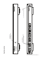
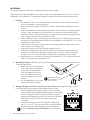
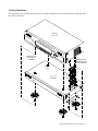
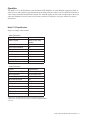
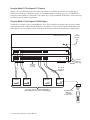
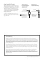
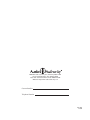
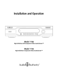
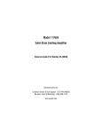
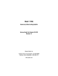
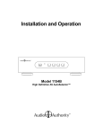
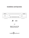
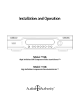
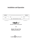
Installation and Operation
HIGH DEFINITION
CAT 5 MULTIDRIVER
POWER
Model 1170
High Definition Cat 5 MultiDriver™ Expander
High Definition
Cat 5 MultiDriver
Expander
A
OUTPUT 1
B
A
OUTPUT 2
B
A
OUTPUT 3
B
A
OUTPUT 4
B
A
OUTPUT 5
Manufactured in the USA by Audio Authority Corporation, Lexington Kentucky • 800-322-8346 or 859-233-4599 • www.audioauthority.com
B
A
OUTPUT 6
B
18V DC
POWER
Installation and Operation Manual
Model 1170
High Definition Cat 5 MultiDriver™ Expander
Audio Authority and the Double-A Symbol are registered trademarks of Audio Authority Corp.
AutoSelect is a trademark of Audio Authority. Copyright November 2006, all rights reserved.
Audio Authority Corporation
Lexington, Kentucky
2
Audio Authority Model 1170 User Manual
Table of Contents
Warnings . . . . . . . . . . . . . . . . . . . . . . . . . . . . . . . . . . . . . . . . . . . . . . . . . . .
3
Getting Started . . . . . . . . . . . . . . . . . . . . . . . . . . . . . . . . . . . . . . . . . . . . . . . .
4
General Information. . . . . . . . . . . . . . . . . . . . . . . . . . . . . . . . . . . . . . . . . . . . . .
4
Carton Contents . . . . . . . . . . . . . . . . . . . . . . . . . . . . . . . . . . . . . . . . . . . . . . . .
4
Other Materials You May Need . . . . . . . . . . . . . . . . . . . . . . . . . . . . . . . . . . . . . . . .
4
Panel Descriptions . . . . . . . . . . . . . . . . . . . . . . . . . . . . . . . . . . . . . . . . . . . . . .
5
Installation. . . . . . . . . . . . . . . . . . . . . . . . . . . . . . . . . . . . . . . . . . . . . . . . . . .
6
Troubleshooting . . . . . . . . . . . . . . . . . . . . . . . . . . . . . . . . . . . . . . . . . . . . . . . .
8
Operation . . . . . . . . . . . . . . . . . . . . . . . . . . . . . . . . . . . . . . . . . . . . . . . . . . .
9
Specifications . . . . . . . . . . . . . . . . . . . . . . . . . . . . . . . . . . . . . . . . . . . . . . . . .
9
Hookup Diagram . . . . . . . . . . . . . . . . . . . . . . . . . . . . . . . . . . . . . . . . . . . . . . . 10
Using Compatible IR Products . . . . . . . . . . . . . . . . . . . . . . . . . . . . . . . . . . . . . . . . 11
Warranty Statement . . . . . . . . . . . . . . . . . . . . . . . . . . . . . . . . . . . . . . . . . . . . . . 11
Warnings
To reduce the risk of fire or electric shock, do not expose this unit to rain or moisture.
!
•
•
•
•
•
•
The exclamation point symbol alerts users to important operating and maintenance instructions
in this manual.
Read these instructions before installing or using this product.
This product must be installed by qualified personnel.
Do not open the cover—there are no user-serviceable parts inside.
Do not expose this unit to excessive heat.
Install only in dry, indoor locations.
Clean the unit only with a dry or slightly dampened soft cloth.
Audio Authority Model 1170 User Manual
3
Getting Started
•
•
•
•
Read these instructions.
Unpack the product and power supply.
Connect associated equipment (detailed instructions are found in the Installation Section).
Connect the product to a suitable power outlet using only the power supply furnished.
General Information
The Model 1170 High Definition Cat 5 MultiDriver™ Expander is a dual-use product. As a companion
product to Models 1166 or 1156, it provides six outputs to Model 9878 Cat 5 HDTV Connection Plates
(Wallplates), with all outputs following the main output of the Model 1166 or 1156. The Model 1170 is mechanically stackable with its host 1166 or 1156, with up to 6 Model 1170s able to be stacked together for a
total of 36 Wallplate outputs.
In its role as a capacity expander for the Model 1171 High Definition Cat 5 MultiDriver™, Model 1170 adds
6 Wallplate outputs. Up to 6 Model 1170s may be stacked with one Model 1171 in this manner, supporting a
total of up to 42 Wallplates.
In conjunction with Model 9878 Wallplates, the Model 1170 provides distribution of audio, video and IR
control signals on Cat 5 cable runs of up to 1,000 feet. The buffered Cat 5 outputs on the Model 1171 drive
from one to six 9878 Wallplates. DC power for each Wallplate is supplied by the Model 1171 through the Cat
5 cable.
The similar Model 1176 may be used with Model 1166 or 1156, if individual source selection of a Wallplate
output is desired. These products are especially well suited for residential use, but professional venues, such
as clubs and restaurants, can also benefit by using them to send selectable video and/or audio to remote
locations. Models 1170 and 1176 may be mixed in one system hosted by a Model 1166 or 1156 when some
Wallplates are to have individually selectable video and some are to have common content as described
above.
Carton Contents
• Model 1170 High Definition Cat 5 MultiDriver™ Expander
• 18-volt Power Supply
Suggested Accessories
•
•
•
•
Model 9878 Cat 5 HDTV Connection Plates
Model 1191 Rack Mounting Adapters secure this model in 19-inch racks
Model 802-567 4-port bus cable—for up to 3 expanders
Model 802-568 7-port bus cable—for up to 6 expanders
Other Materials You May Need
• Infrared receivers for Model 9878 such as Xantech® 291-00
• Universal infrared remote controls
• Category 5e or 6 cable and plugs
4
Audio Authority Model 1170 User Manual
Audio Authority Model 1170 User Manual
5
OUTPUT 1
B
A
OUTPUT 2
B
A
OUTPUT 3
B
A
OUTPUT 4
CAT 5 OUTPUT JACKS
Two Cat 5 cables must be connected
to each Model 9878 Wallplate
POWER
B
POWER INDICATOR
A green LED indicates the
presence of power.
A
OUTPUT 5
Manufactured in the USA by Audio Authority Corporation, Lexington Kentucky • 800-322-8346 or 859-233-4599 • www.audioauthority.com
A
HIGH DEFINITION
CAT 5 MULTIDRIVER
Panel Descriptions
B
A
OUTPUT 6
B
High Definition
Cat 5 MultiDriver
Expander
POWER
Use only the included 18V power supply
18V DC
POWER
Installation
This product should be installed by a qualified custom electronics installer.
These instructions address the Model 1170, which is always used with a Model 1166, 1156 or 1171. Refer to
the Model 1166/56 or Model 1171 instruction manual for complete directions for installing this product.
1. Stacking.
a. Lay the Model 1171 or 1156/66 upside down on a protective surface, such as a terrycloth
towel (see expanded view on facing page).
b. Remove the four feet and the bus port cover and save them and their attaching screws for
later use.
c. Plug one end of the bus cable (purchased separately) into the connector visible through the
bus port—apply enough pressure with a plastic or wooden tool to assure that the plug is
completely seated. A center polarizing key is located on the top of each bus plug. Note that
there is a right end and a wrong end to the bus cable.
d. Turn the Model 1170 to be stacked upside down, thread the bus cable through its bus ports,
and engage its four threaded studs with the four threaded holes in the Model 1171 or 1156/66
formerly occupied by the feet.
e. Tighten the hex head screws in the bottom of the stacking product in sequence a few turns
each, until they are all lightly snug.
f. Plug the next plug of the bus cable into the connector as in 1.c.
g. Continue this stacking procedure until all units have been stacked. Always plug the last
connector of the bus into the bottom unit, pushing any excess cable into the empty space
inside the unit. View the bus through the bus port to be sure all plugs are fully seated.
h. Install the bus port cover and feet you removed from Model 1171 or 1156/66 on the bottom
Model 1170 and turn the stack right side up.
2. Rack Mount Adapters. Do these steps if you are installing this product or a stack of products in a
19-inch equipment rack.
a. Remove the cover screws adjacent
to the front panel of each product
and use them to mount Model
1191 rack adapters. Be sure to
place a cylindrical metal spacer
under the adapters at every screw
CAUTION! This product will
location.
be damaged if spacers are not
used on every screw.
b. Use a straightedge to line up rack
adapters on a stack of product.
!
3. Wallplate Hookup. Caution! Do not connect A and B cables incorrectly. Do not apply system
power until cables are tested and A and B connections are verified.
a. Pull two lengths of good quality Category 5e or 6 UTP cable
Pair 3
from the main system to each Wallplate location. Carefully mark
Pair 2
Pair 1
Pair 4
cables of each pair A and B; if they are connected incorrectly,
damage to the Wallplate may result. It is best to use a different
Modular Jack (RJ-45)
cable jacket color or labels for A and B to insure proper
connection.
1 2 3 4 5 6 7 8
b. Install an RJ-45 plug on each end, using EIA-568B pairing
W-O O W-GR BL W-BL GR W-BR BR
(pins 1-2, 3-6, 4-5, 7-8). Check each cable with a professional
network cable tester before plugging it into the 1100 Series
T568B Pair Assignments
system. Continuity testing is not adequate! The twisted pairs
!
6
Audio Authority Model 1170 User Manual
�������������������
This diagram shows the parts and locations for stacking components. The procedure must be performed with
the units upside down.
Model 1171,
������������
����������������
����������������
��������
����������������
������������������
����������������
���������
�����
�������������
��������
����
�����
��
��
���
��
�
�
��
���
��
��
�
��
Audio Authority Model 1170 User Manual 7
�������������������������������������������������������
must be properly matched for balanced line transmission.
c. Plug the pairs of cables into the output jacks on the Model Model 1170s. Be sure to plug
cables A and B into their respective jacks A and B.
d. Plug a pair of cables into each Model 9878 Wallplate. Be sure to plug cable A into jack A and
cable B into jack B. Do not mount the Wallplates permanently yet.
e. Adjust the Cable Length Compensation control on each Wallplate according to the distance
of that unit from the head end. Set the dial to the nearest number of hundreds of feet of cable
distance. After system power up (see 6, below) use an HD source and display to fine tune
each cable length compensation setting.
f. Mount Wallplates after initial testing.
4. Initial Testing. Plug the power supply furnished with each 1100 Series product into its respective
unit, and plug the power supplies into a wall outlet or plug strip.
a. Check that the power indicators on the Model 1171, all Model 1170s and all Wallplates are
illuminated. When 1170s are present, allow up to 1 minute on initial power-up for the 1171
system to finish self-addressing before starting any tests. The Model 1171 power lamp blinks
slowly while addressing is taking place.
b. Apply power to the source equipment.
c. Check for clear video and audio at each Wallplate using an HD display. Mount the Wallplates.
Using the Cat 5 Infrared Signal Pathway
To enable infrared remote control of head end sources, a Model 9878 Wallplate must have an infrared receiver
(not supplied) plugged into its IR Remote jack. IR remote signals received through a Model 9878 Wallplate
with an IR receiver are repeated through the Model 1166 or 1171 IR Output port. For example, by acquiring
Model 1166 control codes, a learning remote can be used to select sources and control the selected source.
For this feature to work, the Model 1166 IR Output port must be connected to a compatible infrared emitter or
distribution system. See “Using Compatible Infrared Equipment” at the end of this manual.
Model 1170 infrared operation with a Model 1171 is similar, but sources cannot be selected, since there is
only one.
Troubleshooting Guide
Symptom
Picture has artifacts or appears sparkly
Digital audio inoperative
Does not repeat an IR command
One Wallplate inoperative
Wallplates inoperative on one
Model 1171 or 1170
8
Audio Authority Model 1170 User Manual
Possible Cause(s)
Excessive cable length compensation
Neither or both optical and coaxial cables connected to source
Some remotes cannot be processed by this sytem;
IR Output not connected to IR system
Cables swapped or plugs incorrectly pinned out
Bus cable loose or power supply unplugged
Operation
The Model 1170 is the distribution center for Model 9878 Wallplates. At each Wallplate equipped with an infrared receiver and a properly programmed universal infrared remote control, you can control the functions of
video sources located at the main home theater. The same IR remote can also control components in the room
where the Wallplate is located, such as a television, satellite or DVD player. Ask your installer for specific
instructions.
Model 1170 Specifications
Subject to change without notice.
Video Parameters
Signal Type
Component (YPbPr)
Video Formats
480i/p, 576i/p 720p,
1080i/p*
Input Impedance
75 ohms
Input Ground Isolation
No
Gain
1
Gain Accuracy
2%
3dB Bandwidth
100MHz
Input Coupling
AC
S/N Ratio
60dB
Max Gain/Equalization
1
Audio Parameters
Format
Digital/Analog
Digital Audio Input Type
Coaxial/Optical
Input Impedance
75 ohms/50K ohms
Min Load Impedance
75 ohms/10K ohms
Multi-channel Digital
Yes
Frequency Response
10-50KHz
S/N Ratio
75dB
THD+Noise
.07%
Crosstalk
75dB
DC Input Connector
5.5 X 2.1mm Center +
DC Input
18 volts, 1.2 amps
* Model 1170 is compatible with most any video format (including most types of
computer video) as long as the video format does not exceed the maximum bandwidth
of the 1170.
Audio Authority Model 1170 User Manual
9
Using the Model 1170 to Expand 1171 Outputs
Model 1171 Cat 5 MultiDriver provides input connections for an HDTV source such as a satellite box or
DVD player, and up to six Wallplate outputs. To expand the number of outputs, up to six 1170 MultiDriver
Expanders can be added for a maximum of 42 outputs. See “Using Compatible IR Products” on the next page
for infrared control pathway functionality.
Using the Model 1170 to Expand 1156/66 Outputs
The Model 1170 may be used to expand Model 1156 or 1166 AutoSelector outputs, and even used in combination with Model 1176 Matrix Router Expanders. The Model 1170 does not offer matrix functionality, but
rather delivers six Cat 5 outputs with the same audio and video content as the AutoSelector’s main output.
Model 1171, 1166 or 1156
To
compatible
IR emitter
Model 1170
Model 1170
B
18V Power
Supplies to
Power Strip
Add 1170s
or 1176s
as needed
9878
Wallplate
9878
Wallplate
Two runs of
Cat 5e/6 per
Wallplate
9878
Wallplate
This system capacity is 12 Model 9878 Wallplates
(all units display the same input as 1166 Main Output)
10
Audio Authority Model 1170 User Manual
9878
Wallplate
Xantech® 291-00
IR Receiver
or equivalent
12 Volt receiver
Using Compatible IR Products
Receiver Pinout
Receivers are powered
by 12 volts on the sleeve
contact of the 9878
Wallplate IR jack.
Infrared signals may be transmitted from any
Wallplate location back to the 1171 IR output
by connecting a compatible IR receiver to the
Wallplate’s IR jack. The Wallplate provides
12V power to the IR receiver; do not use IR
receivers that provide their own power or
damage could result.
Connect a compatible emitter to the 1171’s
IR output. Use only passive emitters or damage could result.
Tip = Signal
Ring = Ground
Sleeve = +12 Volts
!
Emitter Pinout
A passive emitter usually
has a two-conductor plug.
Tip = Signal
Sleeve = Ground
WARNING: Connect
receivers (12V only) to
Wallplate with no
connecting block or
other power source.
WARNING: Use only
passive emitters,
without a powered
connecting block.
Limited Warranty
Should any consumer use product manufactured by Audio Authority fail due to defects in materials or
workmanship within one year from the date of the original sale to the end-user, Audio Authority guarantees
that we will replace the defective product at no cost. Freight charges for the replacement unit will be paid by
Audio Authority (Ground service only). A copy of the invoice from an Authorized Reseller showing the item
number and date of purchase (proof-of-purchase) must be submitted with the defective unit to constitute a
valid in-warranty claim.
Units that fail after the warranty period has expired may be returned to the factory for repair at a nominal
charge, if not damaged beyond the point of repair. All freight charges for out-of-warranty returns for repair
are the responsibility of the customer. Units returned for repair must have a Return Authorization Number
assigned by the factory.
This is a limited warranty and is not applicable for products which, in our opinion, have been damaged,
altered, abused, misused, or improperly installed. Audio Authority makes no other warranties either
expressed or implied, including limitation warranties as to merchantability or fitness for a particular purpose.
Additionally, there are no allowances or credits available for service work or installation performed in the
field by the end user.
Audio Authority Model 1170 User Manual
11
2048 Mercer Road, Lexington, Kentucky 40511-1071
Phone: 859/233-4599 • Fax: 859/233-4510
Customer Toll-Free USA & Canada: 800/322-8346
Website: http://www.audioauthority.com
Custom Installer
Telephone Number
752-492
12/06