1
Installation and Operation
HD Home Theater Routing System
and
Model 1156 and 1166
High Definition AutoSelector™
Installation and Operation Manual
Compatible with firmware version 2.1
HD Home Theater Routing System
Model 1166
High Definition DVI/Component Video AutoSelector™
Model 1156
High Definition Component Video AutoSelector™
Audio Authority and the Double-A Symbol are registered trademarks of Audio Authority Corp.
AutoSelect is a trademark of Audio Authority. Copyright February, 2007, all rights reserved.
HDMI, the HDMI logo and High-Definition Multimedia Interface are trademarks or registered trademarks of HDMI Licensing LLC.
Audio Authority® Corporation
Lexington, Kentucky
www.audioauthority.com
800-322-8346
Specifications
Audio Parameter
Subject to change without notice.
Format
Digital/Analog
Video Parameter
Digital Audio Input/
Output Type
Optical+Coaxial In/Out
Signal Type
Component+DVI*
Input Impedance
75 ohms/50K ohms
Video Formats
480i/p, 720p, 1080i/p 576i/p
Min Load Impedance
75 ohms/10K ohms
Multi-channel Digital
Yes
Input/Output Impedance
75 ohms
Frequency Response
10-50KHz
Input Ground Isolation
No
S/N Ratio
75dB
Gain
1
THD+Noise
.02%
Gain Accuracy
2%
Crosstalk
25dB
3dB Bandwidth
100 MHz
Power
Input Coupling
DC
DC Input Connector
5.5 X 2.1mm
S/N Ratio
62dB
DC Input/Polarity
18V/Center positive
Max Gain/Equalization
1
Power Supply
571-015
*DVI video is only available on the Model 1166. DVI output is limited to the main output and cannot be accessed from any
remote Wallplate.
Audio Authority AVAtrix, 1156 and 1166 User Manual
Table of Contents
Specifications. . . . . . . . . . . . . . . . . . . . . . . . . . . . . . . . . . . . . . . . . . 2
Warnings . . . . . . . . . . . . . . . . . . . . . . . . . . . . . . . . . . . . . . . . . . . . 3
Getting Started . . . . . . . . . . . . . . . . . . . . . . . . . . . . . . . . . . . . . . . . . 4
General Information. . . . . . . . . . . . . . . . . . . . . . . . . . . . . . . . . . . . . . . 4
Suggested Accessories . . . . . . . . . . . . . . . . . . . . . . . . . . . . . . . . . . . . . 4
Carton Contents . . . . . . . . . . . . . . . . . . . . . . . . . . . . . . . . . . . . . . . . . 4
Other Materials You May Need . . . . . . . . . . . . . . . . . . . . . . . . . . . . . . . . . 5
Panel Descriptions . . . . . . . . . . . . . . . . . . . . . . . . . . . . . . . . . . . . . . . 6
Installation . . . . . . . . . . . . . . . . . . . . . . . . . . . . . . . . . . . . . . . . . . . 8
Troubleshooting . . . . . . . . . . . . . . . . . . . . . . . . . . . . . . . . . . . . . . . . 13
Operating System (Firmware) Upgrade . . . . . . . . . . . . . . . . . . . . . . . . . . . . 13
Entering Source Names and Custom Zones . . . . . . . . . . . . . . . . . . . . . . . . . . 14
Setup Menu Chart . . . . . . . . . . . . . . . . . . . . . . . . . . . . . . . . . . . . . . . 15
Residential Operation . . . . . . . . . . . . . . . . . . . . . . . . . . . . . . . . . . . . . 16
Professional Operation. . . . . . . . . . . . . . . . . . . . . . . . . . . . . . . . . . . . . 17
Hookup Diagrams for 1156/66, 1170 and 1176. . . . . . . . . . . . . . . . . . . . . . . . 18
Appendix A: Using Compatible IR Products. . . . . . . . . . . . . . . . . . . . . . . . . . 21
Appendix B: RS-232 Control Guidelines . . . . . . . . . . . . . . . . . . . . . . . . . . . 22
Warranty. . . . . . . . . . . . . . . . . . . . . . . . . . . . . . . . . . . . . . . . . . . . 24
Warnings
To reduce the risk of fire or electric shock, do not expose this unit to rain or moisture.
!
The exclamation point symbol alerts users to important operating and
maintenance instructions in this booklet.
• Read these instructions before installing or using this product.
• This product must be installed by qualified personnel.
• Do not open the cover—there are no user-serviceable parts inside.
• Do not expose this unit to excessive heat.
• Install only in dry, indoor locations.
• Do not obstruct the ventilation slots.
• Clean the unit only with a dry or slightly dampened soft cloth.
Audio Authority AVAtrix, 1156 and 1166 User Manual
Getting Started
• Register your purchase at www.audioauthority.com/register to activate your warranty and for future upgrade notification. Write the serial number from the rear of the 1156 or 1166 on the back of this manual.
• Read these instructions.
• Unpack the product and its accessories.
• Install batteries in the infrared remote control.
• Connect associated equipment (see detailed instructions in the Installation Section and Hookup Diagrams).
• Connect the product to a suitable power outlet using only the power supply furnished.
• Perform desired setup operations; the PC Configuration Utility included on the flash card is recommended.
!
TIP: To access the menu, press and hold the knob, and touch MENU (or press MENU on the remote).
TIP: To perform password operations, enter “2-3-6, LOAD” on the front panel or remote control.
General Information
The Model 1166/56 High Definition AutoSelector™ complements a wide array of home theater signal sources,
video displays and audio systems. It performs selection of up to six input sources by infrared control, by a
unique AutoSelect™ process, RS-232 signals, or by manual selection. These inputs may be DVI (1166 only)
or component video and digital or analog audio, or combinations of these signal types, all delivered to the
viewer with their original vividness, brightness and clarity. A special feature of the Model 1166 is its built-in
Component-to-DVI converter, which enables the DVI output to be active regardless of the type of video available at the selected input.
NOTE: This manual addresses Model 1166 and 1156 generally but also includes references to DVI capability
which is available only on the 1166. If you are installing a Model 1156, ignore any references to DVI.
HD Home Theater Routing System
The AVAtrix is a configuration of one AutoSelector (Model 1156 or 1166) and one Model 1176 High Definition Cat 5 Matrix Router, which allows up to six remote component video outputs with digital and analog
audio. Commercial venues, such as clubs and restaurants, as well as private homes can benefit by using the
AVAtrix to send selectable video and/or audio to remote locations. Six remote Wallplates (Model 9878) are
included, plus Model 1108 IR router. The Wallplates allow individual source selection by IR remote control;
the output of each Wallplate can also be controlled by the Model 1166. The 1176 delivers component video,
digital and analog audio to each 9878 Wallplate over two Cat 5 cables. The AVAtrix is expandable up to 36
remote Wallplate outputs.
MultiDriver Configurations
Not every application requires matrix router capabilities possible with the 1176. In applications where all displays are to carry the same content, use the Model 1170 High Definition Cat 5 MultiDriver™ to drive multiple
Cat 5 Wallplates with the same program content as the 1166 main component video output. This configuration
still allows switching six sources, but all outputs (up to 36) must show the same source at any given time.
Model 1156 or 1166 Carton Contents (other accessories are included with custom systems or AVAtrix)
•
•
•
•
•
Model 1156 or 1166 High Definition Video AutoSelector™
18-volt Power Supply
Model 1105 Infrared Remote Control with batteries
User Manual
Flash memory card with operational software and setup files (installed in 1166/56 flash card port)
Audio Authority AVAtrix, 1156 and 1166 User Manual
Other Materials You May Need
•
•
•
•
•
Patch cables (RCA, optical and 3.5mm).
Infrared emitters and/or infrared remote control receivers—for Model 9878 IR functionality.
Cat 5e/6 cable—for Models 1170 and/or 1176; consider buying a different jacket color for A and B cables.
RJ-45 plugs—for Models 1170 and/or 1176; EZ RJ-45 plugs are recommended.
Professional network cable tester—for Cat 5 cables; continuity testing is not adequate; the twisted pairs
must be properly matched for balanced line transmission.
Suggested Audio Authority Accessories
• Model 1170 High Definition Cat 5 MultiDriver™ Expander—each expander allows up to six Model 9878
Wallplates to deliver the same content as the Model 1166 output. Maximum 36 Wallplates per system.
• Model 1172 Audio Interface—one required for each Model 1170 or 1176. Provides a connection point for
for a separate whole house audio distribution system.
• Model 1176 High Definition Cat 5 Matrix Router—each Router allows up to six Model 9878 Wallplates to
select any one of the six source inputs to Model 1166. Maximum 36 Wallplates per system.
• Model 9878 Cat 5 HDTV Connection Plates (Wallplates)—allow Model 1170, 1171, or 1176 outputs to be
widely distributed via two Cat 5 cables per Wallplate.
• Model 1192 Rack Mounting Adapters—1166 or 1156 fit 19-inch spacing on EIA rack centers (2 rack units).
• Model 1191 Rack Mounting Adapters—1170 or 1176 fit 19-inch spacing on EIA rack centers (2 rack units).
• Model 1108 IR Router. Plug into the IR Out jack to allow multiple sources to be individually addressed by
9878 Wallplates. For more detail, download the 1108 manual from www.audioauthority.com.
• Model 1183 Active Video DC Blocker—for video sources with DC present in the video output.
• Model 802-567 4-port bus cable—for up to 3 expanders or routers.
• Model 802-568 7-port bus cable—for up to 6 expanders or routers.
• Model 1311 DVI + Digital Audio to HDMI Converter—for HDMI TV displays.
• Model 1312 HDMI to DVI + Digital Audio Converter—for HDMI sources.
• Model 1351 DVI Repeater—for long DVI cable runs.
• Model 1391 HDMI EQ/Extender—for long HDMI cable runs.
• Model 1361 Down Converter—converts component video to composite video.
• Model 1362 Up Converter—converts composite or S-video signals to component video or VGA.
• Model 1365 Video Scaler—converts YPbPr to RGVHV or VGA to YPbPr.
• Audio Authority DVI and HDMI high quality connecting cables and DVI-HDMI adapters.
1365
1166
MAIN OUTPUT
r
Component
Video Display
1361
1311
S-Video or
Composite
Video Display
HDMI
TV Display
HDMI
(DVI)
DV
I
DV
I
1351
DVI
bP
HDMI
YP
YPbPr
RGBHV
RGB
Projector
Pr
YPb
S-Video
(YPbPr)
1365
1312
YPbPr
YPbPr
1362
DVI Source
DVI
YPbPr
Composite Source
HDMI Source
DVI
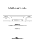
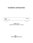
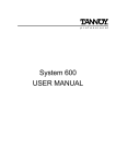
Many possibilities exist for
adapting or actively converting
various signal types to work with
the 1166. Refer to the accessory
descriptions above. Dotted lines
show alternate configurations.
PC
VGA
Y Pb Pr Source
DVI
Video Converter Illustrations
DVI
TV Display
(Long Cable)
DVI
TV Display
Audio Authority AVAtrix, 1156 and 1166 User Manual
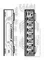
Panel Descriptions
Shown on the page opposite are the front and back views of the 1166. The 1156 is the same, but without DVI
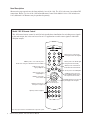
connections. Below is a view of the 1105 Infrared Remote Control. Each Model 1166 or 1156 includes one
1105; additional 1105 Remotes may be purchased separately.
Model 1105 IR Remote Control
This full featured remote control is useful in basic AutoSelector installations for switching source signals
to the main output, but it also can be used in an 1176 application to switch source signals to individual
Wallplate outputs.
MENU key used to access 1166 setup menu
Double click to change from Residential to Professional Mode
*ZONE key used to select
a group of Wallplates
1
2
3
4
5
6
7
8
9
MENU
AUTO
0
ZONE
ALL
UNIT
SOURCE
SCAN
* These keys only work when an 1176 Matrix Router is part of the system.
Audio Authority AVAtrix, 1156 and 1166 User Manual
*ZERO key used to switch between
Residential and Professional Modes
*SOURCE key used to select source
input to Wallplates (Double click for
main output control in Pro Mode)
ENTER
DISPLAY (up/down) used to dim 1166
panel display and for navigation
800/322-8346
www.audioauthority.com
*SCAN keys used to browse
1166 inputs or navigation
*Alpha keys used for navigation
AUTO key used to turn ON/OFF Signal
Sensing AutoSelect functionality
*ALL key used to select all Wallplates
DISPLAY
*UNIT key used to select
a single Wallplate
ENTER key used to make
menu selections
Numeric keys 1-6 used for instant
source input selection and navigation
A
D
G
J
B
E
H
K
C
F
I
L
Audio Authority AVAtrix, 1156 and 1166 User Manual
OPTICAL
DIGITAL
AUDIO
R
L
COAXIAL
DVI VIDEO
OPTICAL
DIGITAL
AUDIO
Pr
Pb
VIDEO
Y
3
R
L
COAXIAL
DVI VIDEO
OPTICAL
DIGITAL
AUDIO
Pr
Pb
VIDEO
Y
4
R
L
COAXIAL
DVI VIDEO
OPTICAL
DIGITAL
AUDIO
Pr
Pb
VIDEO
Y
5
COMPONENT VIDEO INPUT
YPbPr input port for position 1 (these analog
signals are automatically converted to DVI)
LEFT/RIGHT ANALOG AUDIO INPUT JACKS
Connect to every source for proper
Signal Sensing AutoSelection functionality
OPTICAL
DIGITAL
AUDIO
Pr
Pb
VIDEO
Y
6
R
L
COAXIAL
DVI VIDEO
LEFT/RIGHT AUDIO OUTPUT JACKS
Left and right analog audio input signals
are available on these output jacks
COMPONENT VIDEO JACKS
Component video input signals
are available on YPbPr jacks
R
L
COAXIAL
DVI VIDEO
DIGITAL AUDIO OUTPUT JACKS
All digital audio inputs are available at the
coaxial and optical outputs
OPTICAL
DIGITAL
AUDIO
Pr
Pb
VIDEO
Y
R
L
COAXIAL
DVI VIDEO
MENU KEY
Switches between Residential and Professional
Modes, or touch while
pressing the knob to
enter the setup menu
DVI VIDEO MAIN OUPUT
DVI input signals and converted YPbPr input
signals are available on the DVI output
Manufactured in the USA by Audio Authority Corporation, Lexington Kentucky • 800-322-8346 or 859-233-4599 • www.audioauthority.com
Pr
Pb
VIDEO
Y
2
DIGITAL AUDIO INPUT JACKS
Optical OR coaxial inputs for position
1 (DO NOT connect both digital audio
outputs from the same source)
DVI VIDEO INPUT*
DVI input port for position 1
SOFT KEY
Performs the task indicated
on the display (usually
scroll or AUTO on/off)
*DVI capability is only available on the Model 1166. DVI signals are not available on 1176 or 1170 Wallplate outputs.
R
L
COAXIAL
DVI VIDEO
IR WINDOW
Receives infrared
commands
701-12362C
VIDEO
1
POWER LED
When lit,
power is on
INPUT SELECTION
Press a key to switch the
corresponding input to the
DISPLAY
Press to dim the display main output; these keys
(four brightness levels) are also used for setup
OPTICAL
DIGITAL
AUDIO
OUT
IR
IN
High Definition AutoSelector
18V DC
POWER
RS-232 CONTROL
FLASH CARD
POWER JACK
Use only the included
18V power supply
INFRARED OUT
Used only with
1170 or 1176 and
compatible IR products
(see Appendix A)
INFRARED IN
Control 1166 behavior
using separate control
signals
RS-232 PORT
Control 1166 behavior
using a remote control
system
FLASH CARD PORT
Save and load setup
files or use to upgrade
firmware
NAVIGATION AND ENTER KNOB
Turn knob to navigate on-screen menus,
press knob to enter (press and hold knob
and touch MENU to enter setup mode)
Installation
You may wish to consult with a qualified custom electronics installer if you are inexperienced with DVI,
HDMI/HDCP, component video connections and compatibility. If you are installing 1170 or 1176 (AVAtrix),
you should be familiar with Cat 5 cable termination tools, testing and techniques.
Note: This manual addresses Model 1166 and 1156 generally but also includes references to DVI capability which is available only on the 1166. If you are installing a Model 1156, ignore the references to DVI.
1. Pre-Setup. Setup can be performed very conveniently using the Model 1166 PC Configuration Utility.
Setup may also be performed through the 1166 front panel controls, or using the 1105 remote).
a. To set up the 1166 using a PC, remove the flash card from the slot in the rear panel of the 1166
and insert it in an MMC/SD compatible card reader. The utility should launch automatically in any
Windows™ operating system. See page 14 for a screen shot of the Utility. Click the Help button for
detailed instructions. If the utility is not already loaded onto the flash memory card, you may download it from our website at www.audioauthority.com/downloads.php at any time.
b. After saving the setup configuration file, insert the Flash Card into the card slot on the upper right
corner of the back of the Model 1166. Apply power, go to the SETUP menu, choose SAVE/LOAD
FILE, and follow the instructions on the screen.
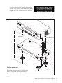
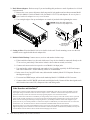
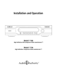
2. Stacking. Follow these steps if you are installing Models 1170, 1172, 1176 or other Audio Authority
stacking models with your 1156 or 1166. Disconnect power before performing these steps.
a. Lay the Model 1166 upside down on a protective surface, such as a terry cloth towel.
b. Remove the four feet and the bus port cover and save them and their attaching screws for later use.
c. Plug one end of the bus cable (purchased separately) into the port visible through the case opening—apply enough pressure with fingers or a wooden or plastic tool to assure that the plug is completely seated. This bus cable carries component video, digital audio, and analog audio signals from
the 1166/56 to the other products in the stack.
d. Turn the next product to be stacked upside down (e.g. Model 1170 or 1176), thread the bus cable
through its bus ports, and engage its four threaded studs with the four threaded holes in the Model
1166 formerly occupied by the feet.
e. Tighten the hex head screws in the bottom of the stacking product in sequence a few turns each, until
they are all snug.
f. Carefully plug the bus cable into the port. Continue this stacking
procedure until all units have been stacked. Always plug the last
connector of the bus into the bottom unit, pushing any excess cable
into the empty space inside the unit. View the bus through the bus
port to be sure all plugs are fully seated. To disconnect a bus plug,
squeeze the side latches.
g. Install the bus port cover and feet you removed from Model 1166
onto the bottom unit and turn the stack right side up.
h. Set the Address dial on each Model 1172 and/or 1176 (Model 1170
does not require addressing)–set the upper-most Model 1176 address to “A”, the next one to “B”, and so on.
i. Temporarily plug in the power supplies of all units to a plug strip
so that you can turn them all on at one time. The opening screen
Audio Authority AVAtrix, 1156 and 1166 User Manual
on the Model 1166 display will indicate that the unit
is powered and how many expanders have been recognized. If this number is different from the number
actually present, look for the bus not being fully
plugged into a unit or a unit incorrectly addressed.
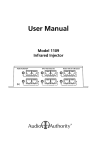
1156 or 1166
REMOVE FEET AND
INSTALL ON LAST
EXPANDER
REMOVE BUS PORT
COVER AND INSTALL ON
LAST EXPANDER
THREADED
STUDS
1170 or 1176
BUS
CABLE
S
BU
RT
PO
ER
OV
S
BU
TC
OR
P
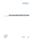
Stacking Components
This diagram shows the parts and locations for
stacking components. The procedure must be
performed with the units upside down.
Audio Authority AVAtrix, 1156 and 1166 User Manual
3. Rack Mount Adapters. Do these steps if you are installing this product or a stack of products in a 19-inch
equipment rack.
a. Remove the cover screws adjacent to the front panel of each product and use them to mount Model
1192 (for Model 1156/66) or Model 1191 (for Model 1170/72/76) rack adapters. Be sure to place a
spacer under the adapters at every screw location.
!
b. Use a straight-edge to line up rack adapters on a stack of product before tightening the screws.
!
CAUTION! This product will be damaged if
spacers are not used on every adapter screw.
IMPORTANT!
Do not mount adapters
without spacers
4. Setting in Place. Place the Model 1166 on its shelf or in the rack. If rack mounting, secure it to the rails
with the screws supplied with the rack adapter kits.
5. Model 1156/66 Hookup. Connect sources, receiver and monitor in these steps.
a. If the AutoSelect feature is to be used, decide now if any devices should be connected directly to the
TV or receiver, particularly if the sources include a device that can record (see below).
b. Connect each source unit to its respective set of Model 1166 input jacks.
c. Use good quality cables and keep the runs under 6 feet if possible, especially for DVI and component video connections—Audio Authority cables are recommended.
d. In the event of very long DVI cable runs, add an Audio Authority Model 1351 Repeater. Please see
the diagram on page 5.
e. If a source has HDMI output, add an Audio Authority Model 1312 HDMI-to-DVI Converter.
f. Connect either, but NOT BOTH optical and coaxial digital audio. Connect all the other signals available from the source unit: DVI, component video and analog audio.
Video Recorders and AutoSelect™
AutoSelect is an exclusive Audio Authority feature designed to automatically select the active input. The Model 1166 uses
input signal changes to determine which one of the six inputs to select. AutoSelect is ideal if most components will not be
powered at one time, because the 1166 looks for newly appearing inputs as one of its decision criteria.
However, another factor must also be considered–you will generally want to keep any source that records, such as a personal
video recorder or PVR, powered up so it can record even when not playing. When a PVR begins to record, it may fool the
Model 1166 into selecting the PVR input, interrupting the device you actually intended to watch. If this happens in your
system, the one way to avoid the problem is to connect the outputs of a PVR directly to a home theater receiver or television
instead of the 1166. The PVR can then be chosen with infrared-controlled manual selection when desired.
High output noise level or other signal deficiencies from a source may cause the Model 1166 AutoSelect logic to fail. If this
happens frequently, the best solution is to deactivate AutoSelect and use the Model 1105 IR Remote (included). You may also
teach the Model 1166 the desired codes of the IR remotes belonging to the sources.
10
Audio Authority AVAtrix, 1156 and 1166 User Manual
g. If a source has HDMI but not DVI output, connect Audio Authority Model 1312 between the source
and its DVI and digital audio jacks on the Model 1166.
h. Connect the television monitor and audio system to the Output jacks, using DVI only, or both DVI
and component video ports if desired. Use either optical or coaxial digital audio outputs, but NOT
BOTH. Use the analog audio output only if the audio system lacks a digital audio input. If the TV
monitor requires HDMI, connect an Audio Authority Model 1311 DVI-to-HDMI Converter. NOTE:
Some HDMI displays will not work correctly with a DVI signal converted to HDMI after a switching device. If your display works properly at first, but fails to work after being turned off and then
on, contact the factory for assistance.
6. Model 1170 or 1176 Wallplate Hookup. If Wallplates are a part of this system, connect them to the stack
now. Caution! Do not connect A and B cables incorrectly. Do not apply system power until cables are
tested and A and B connections are verified.
a. Pull two lengths of good quality Category 5e or 6 UTP cable from the main system to each Wallplate
location. Carefully mark cables of each pair A and B; if they are connected incorrectly, damage to
the Wallplate may result. It is best to use a different cable jacket color, or label each end for A and B
to ensure proper connection.
Pair 3
b. Install an RJ-45 plug on each end, using EIA-568B pairing (pins 1-2,
3-6, 4-5, 7-8). Check each cable with a professional network cable
tester before plugging it into the 1100 Series system. Continuity testing is not adequate! The twisted pairs must be properly matched for
balanced line transmission.
c. Plug the pairs of cables into the output jacks on the Model 1170s.
Carefully plug cables A and B into the correct A and B jacks.
d. Plug a pair of cables into each Model 9878 Wallplate. Be sure to
plug cable A into jack A and cable B into jack B. Do not mount the
Wallplates permanently yet.
Pair 2
Pair 1
Pair 4
Modular Jack (RJ-45)
1 2 3 4 5 6 7 8
W-O O W-GR BL W-BL GR W-BR BR
T568B Pair Assignments
e. Adjust the Cable Length Compensation control on each Wallplate according to the distance of that
unit from the head end. Set the dial to the nearest number of hundreds of feet of cable distance. After
system power up (see 7, below) use an HD source and display to fine tune each cable length compensation setting.
f. Mount Wallplates after initial testing.
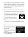
7. Initial Testing. Plug the power supply furnished with each 1100 Series product into its respective unit,
and plug the power supplies into a plug strip so that all units can be turned on at one time.
a. Power indicators on the Model 1166, all stacked units and all installed Wallplates should be on.
b. The opening screen on the Model 1166 display indicates that the unit is powered and how many expanders have been recognized. That number is zero if the
Model 1166 is used alone.
c. If you see an address error, enter the setup menu and
choose Diagnostics. The 1170/72/76 Diagnostics
screen allows real time address feedback. Make necessary adjustments to the 1176 and 1172 address dials
(see page 8) and exit.
d. Apply power to all associated equipment. Touch the
input selection keys to manually select sources to
verify video and audio signal integrity.
Opening screen showing zero 1170s and zero 1176s.
Diagnostic screen showing the second 1176 addressed incorrectly.
Audio Authority AVAtrix, 1156 and 1166 User Manual
11
e. If both component video and DVI are connected to the video display, test the display both ways by
switching its inputs. Any component video sources should also be shown with the TV in DVI mode.
8. Real-time Setup. If setup configurations were not downloaded from the flash card (page 8), perform
desired setup tasks. For convenience, the PC Configuration Utility is recommended for most setup tasks,
but all tasks may also be performed using the front panel controls or remote control. As a minimum, it is
recomended that you enter custom source names and save your setup configuration to the flash card.
To enter the Setup Menu, press and hold the knob, and touch the Menu key (or simply press Menu on the
remote). Use the knob to navigate to each setup option, press the knob to select it, then follow on screen
instructions (see page 15 for a Setup Menu Chart).
9. Remote Control Methods. Four different remote control methods may be used with the 1156/66.
a. Native remote; use Model 1105.
b. Source or universal remotes; commands can be learned by 1156/66 using the Learn IR Codes setup
screen (see section 10 below).
c. Home automation systems can learn the Model 1166’s IR codes along with the codes of the sources
and can output a macro containing source controls and Model 1166 selection controls. Follow the
manufacturers instructions to teach the automation system numeric 1 through 6 from the Model
1105, as needed. Some automation systems allow 1105 codes to be downloaded from the manufacturer’s website and then loaded into the automation system controller.
d. RS-232 commands. System controllers capable of RS-232 communication can be connected to the
serial port on the Model 1166. To program such controllers, refer to Appendix B in this manual.
10.Using Infrared Control.
a. If you are using standard handheld remote controls, ensure correct operation by eliminating sources of
light pollution such as direct sunlight, fluorescent light, etc.
b. If you are using a home automation system (such as Crestron, AMX, CQC, or Control4), provide a contact
emitter or blaster from the infrared system to stimulate the Model 1166’s optical IR receiver, or patch the
IR signal directly to the IR input port on the rear panel using a 3.5mm cable (see page 7).
11.Infrared Learning. In addition to using the Model 1105 remote, or using other learning remotes to send
1105 commands, the 1166 can learn to respond to existing commands from source remotes. This control
method offers versatility and precision in source selection with a small investment of time to teach the IR
commands to the 1166. Following are steps to learn IR codes from source remotes.
a. Use the Learn IR Codes setup screen to teach the Model 1166 one “key” code for each source unit.
For example, for a media player, let the Model 1166 learn its “play” key, then, when that key is
pressed to start the player, the Model 1166 will immediately select its output. On a set top box, one
might pick the “enter” key to prompt the Model 1166 to switch when a channel has been selected.
b. Audio Authority Model 1108 IR Router (included in AVAtrix) addresses the problem of controlling
multiple identical sources from a Wallplate. The Model 1108, when used with individual IR emitters
attached to the sources, routes the IR command from a Wallplate to the appropriate source only.
12. Remote Wallplates. The Cat 5 cables carrying audio and video to the Wallplates also provide a pathway
for infrared signals to be returned to the 1170 or 1176.
a. Plug an Infrared Control Receiver into the 3.5mm jack on each Wallplate used with a Model 1176
that is to have source selection capability. (Use only compatible receivers without power supply–see
Appendix A.)
12
Audio Authority AVAtrix, 1156 and 1166 User Manual
b. Infrared commands returned from a Wallplate to Model 1176 can immediately select the source to be
played on that Wallplate.
c. 1176: IR commands returned from a Wallplate to Model 1176 containing code intended for source
units or other equipment are repeated through the IR Output jack on the Model 1166. If a compatible
infrared control system is in place, and remote sensing of IR inputs from Wallplate locations is desired, patch the IR Output jack to an input of the IR control system. Do not use IR connecting blocks
other than Model 1108 (see “Using Compatible Infrared Products” in Appendix A of this manual).
d. 1170: All IR commands returned from a Wallplate to Model 1170 are repeated only through the IR
Output jack and perform no function within the switching system.
Troubleshooting
If the 1156 or 1166 system fails to respond as expected, use the outline below to find the cause or narrow
the possibilities. If your question is not answered in this guide, call Audio Authority Technical Support at
800‑322‑8346. Visit www.audioauthority.com for firmware upgrades and other information.
Symptom
Possible Cause(s)
No DVI video on monitor
Non-HDCP monitor*;
Passively adapted HDMI source and monitor** (Use Model 1312 to convert source
signals)
DVI picture has artifacts
Cable(s) too long or poor quality (Use Model 1351 DVI Repeater for long cable runs)
DVI switching has delay
Normal result of HDCP handshaking
Switches to undesired input with Auto off
Wrong IR code stored
Switches to undesired input in Auto mode
Recording source giving false switch criteria (turn Auto OFF or connect recording source
directly to TV)
Does not autoselect a certain source
Digital or analog audio not available or connected;
A source is recording
Does not respond to a learned IR command Wrong IR code learned or IR remote cannot be learned
Does not respond to RS-232
1166 commands not stored in remote control system (see Appendix B)
Does not repeat a certain IR remote
Some IR remotes cannot be processed;
IR Output not connected to IR system
Expander is not recognized
Bus cable loose, 1170, 1172 and 1176 incorrectly addressed, or power supply not
connected (Use Diagnostics in 1166 setup menu)
* The 1166 will not correct source/display incompatible conditions that may occur when the sources or display are not HDCP compliant.
** The 1166 may not function properly with a system including both an HDMI soure and an HDMI display without active conversion using Model 1311 and
1312 (see page 5).
Performing an Operating System Upgrade from a Flash Card
1. Place flash card containing the latest operating system data into card slot at rear of 1156/66.
2. Press encoder knob and touch “menu” key. Setup screen appears. Scroll and choose “Save/Load File”.
3. Scroll and choose “Upgrade 1156/66 operating system.” Upgrade screen appears.
4. Touch in order 2, 3, 6 then (softkey) “Load”.
5. Scroll and select the latest operating system (e.g. “06 Feb 2007 1166 Sys 2.0”).
After you select the version you want the screen displays “Downloading...” This step takes up to a minute. After the
screen displays “Completed” the unit reboots several times.
Audio Authority AVAtrix, 1156 and 1166 User Manual
13
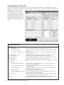
Customizing the 1156 or 1166
One of the features that sets the Model 1156 or 1166 apart from other products is customization. It is easy to
apply your own source names, create zones and apply zone names, lock out certian functions, and add contact
information. The easiest way to
configure the system is to use the
PC Configuration Utility, shown at
the right; however, any configuration may be performed via the front
panel controls and/or remote control. Refer to the Setup Menu Chart
below.
Setup Menu Chart
Settings (Options)
Lockout AutoSelect
Lockout Front Panel Keys
Lockout Front Panel IR Detector
Enable Display Blanking
Name the Sources
Learn IR Commands
Name the Zones
Assign Output Zones
Save/Load File
Save Current Setup to Flash Card
Load New Setup from Flash Card
Load Demonstration Setup
Load Default Setup
Upgrade 1156/66 Operating System
Contact Installer
Diagnostics
14
Prevents AutoSelect from being activated by the front panel or IR.
Lockout all front panel keys except for Display and the key sequence for Setup
Menu access.
Ignores any IR commands visible from the front panel IR window; IR input jack
on rear is still active.
Enables blanking of display after 45 seconds of inactivity (keytouch or IR).
Assign default, custom and custom long names to each source.
Teach the Model 1166 which IR commands of associated equipment to follow.
Choose zone names from a list or enter custom zone names.
Divide the array of Model 1176 Wallplate outputs into geographic or functional
zones.
Save the current setup configuration to memory card in rear slot. Does not
overwrite any existing setup files.
Scan and load setup data saved from an 1166 or saved from the 1166PC
Configuration Utility.
Loads example setup including custom short and long source names and 24
simulated remote Wallplate locations.
Clears user setup and loads factory default setup.
Choose from available 1156/66 operating system firmware files on the flash
memory card to install a firmware upgrade.
The installer may enter contact information for the owner’s convenience. Enter
up to four lines of information, 42 characters per line.
1176 Address Diagnostic shows letter address of all detected 1176 expanders.
Other diagnostics may be added in later system firmware releases.
Audio Authority AVAtrix, 1156 and 1166 User Manual
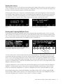
Naming the Sources
While naming the sources is not required, source names greatly enhance the usability of your entire system. It
is easy to customize your source names using the PC Configuration Utility (shown on the previous page), but
the names can also be chosen using the 1166 front panel controls.
Each long name can be up to 13 characters, and the short names can be up to 4 characters. The text edit tools
are indicated along the bottom of the screen: Case/Number/Symbol, Skip Back, Skip Forward, Overstrike/Insert, and Delete. Touch the corresponding key to use an editing tool. The Case tool allows upper and lower
case letters, numbers, or symbols. Note: using all upper case generally yields the best results.
Customizing source names makes it easier to navigate your audio/video
system.
The text edit tools are indicated along the bottom of the screen: Case, Skip
Back, Skip Forward, Overstrike/Insert, and Delete.
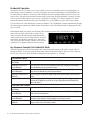
Naming and Assigning Wallplate Zones
Professional mode allows the Wallplate outputs to be monitored and controlled from the 1156 or 1166 front
panel. The Zone View displays a list of up to six zones and indicates which source has been assigned to each
zone. This view makes it easy to monitor and manage the content being shown on video displays in different
rooms or areas from a central location. The number of zones is limited to six.
The Zone view allows the user to see the name of the locations and the
sources. Asterisk (*) indicates that one or more of the Wallplates in the zone
has been assigned a different source than the one shown.
1
2
3
4
5
6
Zone Name
Zone Number
To create custom zones, enter the setup menu and select Name the Zones. Choose names from a list or enter
custom short and long zone names for each zone. Exit the Name the Zones screen and select Assign Output
Zones. A view of the Assign Output Zones screen is shown above at the right. Any Wallplate can be assigned
to any or all zones, and the Main output can belong to any or all zones. Notice that each row of the grid represents one 1176 Matrix Router. To the left is the address letter of each 1176. Above is the output number of the
Wallplate output in each column.
To assign a Wallplate to a zone, use the knob or up/down/left/right keys on the remote control to highlight a
Wallplate. Touch the number key(s) of the zone(s) to which this Wallplate should belong. (Zones are numbered 1-6 as noted in th example above.) To remove a Wallplate from a zone, touch the number key again.
In the example shown above at right, both Wallplate 1 and Main belong to Zone 1 which is named LVRM.
Plate 2 belongs to BED1 (Zone 3) and so on. It is usually helpful to write down a list of Wallplates for each
zone before assigning zones, especially if your system is very large or complex.
Audio Authority AVAtrix, 1156 and 1166 User Manual
15
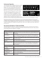
Residential Operation
The Model 1166 or 1156 allows you to select which of up to six video/audio sources to play through your
home theater system. In addition, if you have an AVAtrix, the source being displayed at each Wallplate can
be controlled by the Model 1156/66 and, if the Wallplate location is equipped with an infrared receiver, the
source can be selected using an infrared remote control in the room where the Wallplate is located. You may
wish to use Professional mode if your system is an AVAtrix or includes 1176 matrix expanders. To switch
between Residential and Professional, press the MENU key, or the ZERO key on the 1105 remote control.
If your whole-house video distribution system uses Model 1170s, all Wallplate locations automatically display
the same program content as the Main Output of the Model 1156/66. Residential mode is appropriate for this
type of system.
In Residential mode, the normal screen displays the custom long name of the selected source, the six short
names of the sources, which of these sources is currently selected to the Main Output (highlighted short
name), which sources are currently active (overscored
short name), and whether AutoSelect™ is On or Off.
Ask your professional installer whether you should use
AutoSelect™ or another method of source selection.
Residential Mode in Unit view. Press Menu key to change to Professional.
Key Sequence Examples for Residential Mode
This table explains how to perform example tasks using front panel controls or IR remote control while in
Residential Mode. To navigate using the front panel controls in the Select Remote Sources screen, rotate the
knob to move the cursor, press the knob to change directions (up/down vs. left/right).
1105 Remote Control
Changing the source on the
Main Output
Changing the source on a
remote Wallplate
Changing the source for a
zone of Wallplates
Changing the source for all
Wallplates
Assign a Wallplate to Zone 3
Press the desired number key or press the Left/Right Scan keys.
Press Zero; press Unit; use the up/down/left/right keys to highlight the Wallplate;
press the Number key for the desired source.
Press Zero; press Zone (if necessary); use the up/down keys to highlight the desired
zone; touch the Number key for the desired source.
Press Zero; press All; press the Number key for the desired source. (Press Enter to
undo.)
Press Menu; press the down key and select Assign Output Zones by pressing Enter;
navigate to the Wallplate you wish to assign using up/down and left/right keys;
press 3 for Zone 3.
1166 Front Panel Controls
Changing the source on the
Main Output
Changing the source on a
remote Wallplate
Changing the source for a
zone of Wallplates
Changing the source for all
Wallplates
16
Touch the desired Number key or turn the knob.
Touch Menu; turn the knob to navigate; when the desired Wallplate is highlighted,
touch the desired Number key.
Touch Menu; Touch soft key until Zone is indicated; turn the knob to select the zone
number desired; touch the desired Number key to assign a source.
Touch Menu; Touch soft key until All is indicated; touch the desired Number key to
assign a source. (Press the knob to undo.)
Audio Authority AVAtrix, 1156 and 1166 User Manual
Professional Operation
The Professional mode is designed to allow easy control
of 1176 (AVAtrix) remote Wallplate outputs from the
Model 1166 or 1156. If your system does not include
an 1176, use the Residential Mode. Switch between
Residential and Professional by touching the front panel
Menu key or by pressing the Zero key on the remote.
Professional mode in Unit view. Press soft key to change views.
The Professional screen displays the source currently
assigned to each Wallplate or zone and allows you
to choose a new source for each Wallplate or zone. A
special zone view is also available for a more detailed
overview of the sources assigned to each zone. If the
Professional mode in Zone view. (Not available if no zones are assigned.)
Wallplate location is equipped with an infrared receiver,
the source can also be selected using an infrared remote control in the area where the Wallplate is located.
In Professional mode, the Unit screen displays the array of remote outputs (if Model 1176s are present).
Along the bottom, it displays the six short names of the sources, which of these sources is currently selected
to the Main Output (highlighted short name), and which sources are currently active (overscored short name).
To the left it displays the virtual Main, All and Zone keys. Note: to access Main on the remote, double-press
the Source key.
Key Sequence Examples for Professional Mode
This table explains how to perform example tasks using front panel controls or IR remote control while in
Professional Mode. To navigate using the front panel controls, rotate the knob to move the cursor, press the
knob to change directions (up/down vs. left/right).
1105 Remote Control
Changing the source on the
Main Output
Changing the source on a
remote Wallplate
Double-press the Source key to indicate Main; press the desired number key or use
the Scan keys.
Press Unit; press Letter and Number key for the desired Wallplate; press Source;
press the Number key for the desired source. Alternative: use the up/down/left/
right keys to highlight the Wallplate; press the Number key for the desired source.
Changing the source for a
Press Zone; use the up/down keys to show the desired zone; touch the Number key
zone of Wallplates
for the desired source.
Changing the source for all Press All; press the Number key for the desired source input. (Press Enter to undo.)
Wallplates
Main is not included in this command.
Assign a Wallplate to Zone 3 Press Menu; press the down key and select Assign Output Zones by pressing Enter;
navigate to the Wallplate you wish to assign using up/down and left/right keys;
press 3 for Zone 3.
1166 Front Panel Controls
Changing the source on the Press the soft key until Main is indicated; touch the desired Number key or turn the
Main Output
knob.
Changing the source on a
Press the soft key until Unit is indicated; use the knob to highlight the desired
remote Wallplate
Wallplate; touch the desired Number key.
Changing the source for a
Press the soft key until Zone is indicated; turn the knob to show the desired zone;
zone of Wallplates
touch the desired Number key.
Changing the source for all Press the soft key until All is indicated; touch the desired Number key. (Press the
Wallplates
knob to undo.)
Audio Authority AVAtrix, 1156 and 1166 User Manual
17
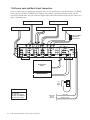
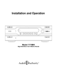
1166 Source Input and Main Output Connections
Up to six sources may be connected to the Model 1166 or 1156 AutoSelector (1166 shown below). An HDMI
source requires a model 1312 HDMI to DVI adapter. All available connections should be made, with the
exception of digital audio; only one of the two digital audio connections should be made for each source. (See
page 11 for instructions.)
DVI SOURCE
COMPONENT VIDEO SOURCE
COMPONENT VIDEO SOURCE
DVI SOURCE
HDMI SOURCE
Model 1312 HDMI
to DVI+Digital
Audio Converter
AA
AC
AA
VC
AO
VD
AC
VD
AA VC
AA
VD
AC
AC
AA
VD
VC
AA AC
DVI TELEVISION
DISPLAY
HOME
THEATER
RECEIVER
DIGITAL
RECEIVER
OR AMPLIFIER
18V
Power
Supply
LEGEND
VC
VD
AC
AO
AA
18
Video-component
Video-DVI
Audio-coax (Digital)
Audio-optical (Digital)
Audio-analog Stereo
Audio Authority AVAtrix, 1156 and 1166 User Manual
From Home
Theater
Controller
IR to 1166
RS-232 to 1166
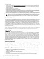
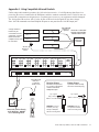
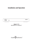
and other 1176 Matrix Router Configurations
Multiple Wallplates may be connected to a Model 1166 with Model 1176 Matrix Routers. A single 1176 has
a capacity of six Wallplates. IR signals sent over Cat 5 through the 1176 are then sent through the 1166 and
retransmitted on the IR ouput jack. IR signals from the 1105 (or other enabled remotes) are interpreted by the
1176 and affect only the output of the Wallplate originating the IR. If the system has multiple sources sharing
the same IR code, a Model 1108 Multi-source IR Router should be used.
SOURCE 1
SOURCE 2
SOURCE 3
SOURCE 4
SOURCE 5
SOURCE 6
MAIN OUTPUT
To IR
distribution
system
1166 or 1156
1176
A
1176
B
18V Power
Supplies to
Power Strip
Add 1176s
or 1170s as
needed
Address = B
Two runs of
Cat 5e/6 per
Wallplate
9878
Wallplate
9878
Wallplate
9878
Wallplate
9878
Wallplate
Model 9878 Detail
This system capacity is
12 Model 9878 Wallplates
(each has selectable input)
IR Receiver
ANTENNA
DIGITAL AUDIO
IR REMOTE
Y
Pb
VIDEO
Pr
LEFT RIGHT
AUDIO
MODEL 9878 www.audioauthority.com
1105
Remote
Control
Universal
Remote
Control
Audio Authority AVAtrix, 1156 and 1166 User Manual
19
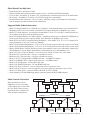
1170 MultiDriver Expander Connections
Multiple Wallplates may be connected to a Model 1166 with Model 1170 MultiDrivers. A single 1170 has a
capacity of six Wallplates. IR signals sent over Cat 5 and through to the 1170 are then sent through the 1166
and retransmitted on the IR ouput jack. 1105 IR signals from Wallplates connected through the 1170 do not
control switching.
SOURCE 1
SOURCE 2
SOURCE 3
SOURCE 4
SOURCE 5
SOURCE 6
MAIN OUTPUT
To IR
distribution
system
1166 or 1156
1170
1170
18V Power
Supplies to
Power Strip
Add 1170s
or 1176s
as needed
9878
Wallplate
9878
Wallplate
Two runs of
Cat 5e/6 per
Wallplate
9878
Wallplate
9878
Wallplate
This system capacity is 12 Model 9878 Wallplates
(all units display the same input as 1166 Main Output)
Model 9878 Detail
ANTENNA
DIGITAL AUDIO
IR REMOTE
Y
Pb
VIDEO
Pr
LEFT RIGHT
AUDIO
MODEL 9878 www.audioauthority.com
20
Audio Authority AVAtrix, 1156 and 1166 User Manual
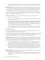
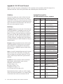
Appendix A: Using Compatible Infrared Products
Unlike other Audio Authority products, the 1100 series has an active, 12 volt IR pathway that allows it to
power the IR receivers connected to the Wallplates, and drive emitters connected to the 1156/66. Do not use
Unlike other Audio Authority products, the 1100 series has an active IR pathway, allowing it to
powered IR systems that are designed to use a separate power source or your equipment could be damaged.
power the IR receivers connected to the Wallplates, and drive emitters connected to the 1166. Do
The 1166 powers IR receivers with 12 volts; do not use IR receivers designed for any other voltage.
not use powered IR systems that are designed to use a separate power source or your equipment
Note: 1105 IR commands sent from Wallplate IR ports are not passed to the 1166 IR Output jack.
could be damaged. The 1166 powers IR receivers with 12 volts; do not use IR receivers designed
for any other voltage.
A single emitter or
blaster may be
connected to the IR
output jack, or use the
Model 1108 when
multiple sources must
be controlled.
Source 1
Xantech® 282M
IR Emitter or
Do not use a connection
equivalent
Source 1
block or signal amplifier
with the 1166 or 1156.
Source 2
Source 2
Source 3
Model 1108
IR ROUTER
Source 3
Two-wire
IR blaster or
emitter
1166 or 1156
-OR-
1176
Xantech® 291-00
IR Receiver
or equivalent
12 Volt receiver
Receiver Pinout
Receivers are powered
12 volts
volts on
on the
the sleeve
sleve
by 12
contact of the 9878
Wallplate IR jack.
Tip = Signal
Ring = Ground
Sleeve = +12 Volts
9878
Wallplate
WARNING: Connect
receivers (12V only)
directly to Wallplate,
without connecting block.
Connect IR receiver directly
to the Wallplate - DO NOT
use a connecting block.
Emitter Pinout
A passive emitter usually
has a two-conductor plug.
Tip = Signal
Sleeve = Ground
WARNING: Use only
non-powered emitters,
without connecting block.
Remote
Control
Audio Authority AVAtrix, 1156 and 1166 User Manual
21
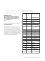
Appendix B: RS-232 Serial Protocol
Model 1166 and 1156 with or without Model 1176 expanders can be controlled via RS-232 from a PC or
dedicated controller. Follow the specifications and command protocol described below.
Guidelines
The RS-232 control port on the 1156/66 is fixed at
9600 baud. There is no provision for flow control
(XON/XOFF, DTR, etc.). On power up, the 1156/66
echoes any received character, but that echo function
may be turned off as described at the end of this section to prevent corruption of replies.
Definitions
Command: String received by the 1156/66 from the
controlling hardware. Commands are not case sensitive and may be 7 or 8-bit with Odd, Even, Space,
Mark, or No parity. The only characters recognized
are: letters (a-z and A-Z), numbers (0-9), brackets
([ and ]), signs (+ and -), and the question mark (?).
All other characters, including spaces and commas,
are optional and may be either included for clarity or
omitted entirely.
Response: String transmitted by the 1156/66 to the
controlling hardware. Responses are 8-bit with no
parity. Responses are transmitted as noted below,
and always have a C/R L/F sequence (0x0d, 0x0a)
after each line.
Query: A special command that requests the current
status of one or more connections or settings, but
does not change any operation within the 1156/66.
A query must always contain the ? question mark
character.
Parameters: Values contained within commands
and responses which identify zones, sources,
Wallplates, and router devices.
j: zone in range {1-6}
m: source in range {1-6}
n: Wallplate in range {1-6}
x: A/V router device in range {A-L}
In this document, braces { and } are used to signify
ONE of the enclosed characters. For example, {L,U}
would mean either of the two characters L or U.
22
Audio Authority AVAtrix, 1156 and 1166 User Manual
Extended Command Set: All valid commands receive a response.
Command:
Response:
Description:
[C,M,Im]
(M,Im)
Connect main output to source
m
[C,Rx,On,Im]
(Rx,On,Im)
Connect Wallplate n of A/V
router x to source m
[C,X,Im]
(X,Im)
Connect all Wallplates on all
A/V routers to source m
[C,Zj,Im]
(Zj,Im)
Connect all outputs in zone j
to source m
[L,P]
(P,L)
Lock out front panel controls
[U,P]
(P,U)
Unlock front panel controls
[L,I]
(I,L)
Lock out internal I/R receiver
[U,I]
(I,U)
Unlock internal I/R receiver
[L,A]
(A,L)
Lock out AutoSelect function
[U,A]
(A,U)
Unlock AutoSelect function
[+,B]
(B,+)
Turn on display blanking after
45 seconds of inactivity
[-,B]
(B,-)
Turn off display blanking
[+,P]
(P,+)
Select Professional Screen
[-,P]
(P,-)
Select Residential Screen
[+,A]
(A,+)
Turn on AutoSelect if not
disabled (see Q+, Q- below)
[-,A]
(A,-)
Turn off AutoSelect
Query:
Response:
Description:
[?,C,Rx,On]
(Rx,On,Im)
Query unit connection
[?,C,M]
(M,Im)
Query main connection
[?,C,X]
see below
Query all connections
[?,{L,U},P]
(P,{L,U})
Query status of panel lockout
[?,{L,U},I]
(I,{L,U})
Query status of internal I/R
lockout
[?,{L,U},A]
(A,{L,U})
Query status of AutoSelect
lockout
[?,{+,-},B]
(B,{+,-})
Query status of Display blanking
[?,{+,-},P]
(P,{+,-})
Query status of Display
Screen
[?,{+,-},A]
(A,{+,-})
Query status of AutoSelect
function
Any command not in the Exended Command Set
which begins with a left bracket [ and ends with
a right bracket ] is an invalid command and the
1156/66 responds with the string (ERROR).
Response to [?,C,X] :
(RA,O1,Im)(RA,O2,Im)(RA,O3,Im)(RA,O4,Im)
(RA,O5,Im)(RA,O6,Im)(RB,O1,Im)(RB,O2,Im)
(RB,O3,Im)(RB,O4,Im)(RB,O5,Im)(RB,O6,Im)
. . . through all devices . . .
(M,Im)
Power Up, Extended Commands and their Effect on Echo Function
On power up, the 1156/66 sends the string (RESET). The 1156/66 also echoes any data received
on the RS-232 port. If any valid normal command
is received (commands beginning and ending with
brackets [ and ]), the 1156/66 ceases echoing characters to prevent these echoed characters from corrupting responses. The echo function remains off until
the 1156/66 is reset, either by interrupting power or
by double-pressing the front panel knob.
Abbreviated Command Set:
Only query commands receive a response
Command:
Response:
Description:
Mm
(no response) Connect main output to
source m
Uxnm
(no response) Connect Wallplate n of A/V
router x to source m
Xm
(no response) Connect all Wallplates on all
A/V routers to source m
Zjm
(no response) Connect all outputs in zone j
to source m
P
(no response) Select Professional Screen
R
(no response) Select Residential Screen
N+
(no response) Turn on AutoSelect if not
locked out (see Q+, Qbelow)
N-
(no response) Turn off AutoSelect
Q+
(no response) Lock out AutoSelect function
Q-
(no response) Unlock AutoSelect function
V+
(no response) Lock out front panel controls
V-
(no response) Unlock front panel controls
W+
(no response) Lock out internal I/R receiver
W-
(no response) Unlock internal I/R receiver
Y+
(no response) Turn on display blanking after
45 seconds of inactivity
Y-
(no response) Turn off display blanking
Query:
Response:
Description:
?{P,R}
={P,R,S}
Query status of display
screen
(Professional, Residential,
or Setup)
?{N,Q,V,W,Y} ={+,-}
Query status of setting (see
above for descriptions)
?M
=m
Query status of main output
?Uxn
=m
Query status of any single
Wallplate output
Audio Authority AVAtrix, 1156 and 1166 User Manual
23
2048 Mercer Road, Lexington, Kentucky 40511-1071 USA
Phone: 859-233-4599 • Fax: 859-233-4510
Customer Toll-Free USA & Canada: 800-322-8346
Website: www.audioauthority.com
Limited Warranty
Should any consumer electronics product manufactured by Audio Authority fail due to defects in
materials or workmanship within one year from the date of the original sale to the end-user, Audio
Authority guarantees that we will replace the defective product at no cost. Freight charges for the replacement unit will be paid by Audio Authority (Ground service only). A copy of the original invoice
from an Authorized Reseller showing the item number and date of purchase (proof-of-purchase) must
be submitted with the defective unit to constitute a valid in-warranty claim.
Units that fail after the warranty period has expired may be returned to the factory for repair at a
nominal charge, if not damaged beyond the point of repair. All freight charges for out-of-warranty
returns for repair are the responsibility of the customer. Units returned for repair must have a Return
Authorization Number assigned by the factory.
This is a limited warranty and is not applicable for products which, in our opinion, have been damaged, altered, abused, misused, or improperly installed. Audio Authority makes no other warranties
either expressed or implied, including limitation warranties as to merchantability or fitness for a particular purpose. Additionally, there are no allowances or credits available for service work or installation performed in the field by the end user.
Serial Number _________________________________
Custom Installer ________________________________
Telephone Number ______________________________
v 2.1
752-483
4/07