1
AKD®
PROFINET RT Communication
Edition: Revision G, December 2014
Valid for firmware version 1.13
Part Number 903-200012-00
Original Documentation
Keep all manuals as a product component during the life span of the product.
Pass all manuals to future users and owners of the product.
Record of Document Revisions
Revision
...
Remarks
Table with lifecycle information of this document see "Record of Document Revisions" (➜ p.
50)
E, 12/2013
Added bit 14 for position mode in Status word bits (ZSW1) (➜ p. 33).
F, 05/2014
Added Signal No. 100 and 101 to Telegram configuration (➜ p. 35). Added Manufacturer specific telegram 352 to I/O Telegrams (➜ p. 41).
G, 12/2014
Manufacturer specific telegram 353 (➜ p. 42) added. Signal number 102 and 103 added to Telegram configuration (➜ p. 35). Acc-/Deceleration Units (➜ p. 43) scaling information added.
Trademarks
l
l
l
l
l
l
l
l
l
l
AKD is a registered trademark of Kollmorgen Corporation
EnDat is a registered trademark of Dr. Johannes Heidenhain GmbH
EtherCAT is a registered trademark and patented technology, licensed by Beckhoff Automation GmbH
Ethernet/IP is a registered trademark of ODVA, Inc.
Ethernet/IP Communication Stack: copyright (c) 2009, Rockwell Automation
sercos® is a registered trademark of sercos® international e.V.
HIPERFACE is a registered trademark of Max Stegmann GmbH
PROFINET is a registered trademark of PROFIBUS and PROFINET International (PI)
SIMATIC is a registered trademark of SIEMENS AG
Windows is a registered trademark of Microsoft Corporation
Current patents
l
l
l
l
l
US Patent 5,162,798 (used in control card R/D)
US Patent 5,646,496 (used in control card R/D and 1 Vp-p feedback interface)
US Patent 6,118,241 (used in control card simple dynamic braking)
US Patent 8,154,228 (Dynamic Braking For Electric Motors)
US Patent 8,214,063 (Auto-tune of a Control System Based on Frequency Response)
Technical changes which improve the performance of the device may be made without prior notice!
Printed in the United States of America
This document is the intellectual property of Kollmorgen. All rights reserved. No part of this work may be reproduced in any form (by photocopying, microfilm or any other method) or stored, processed, copied or distributed
by electronic means without the written permission of Kollmorgen.
2
Kollmorgen | December 2014
AKD PROFINET | Table of Contents
1 Table of Contents
1 Table of Contents
2 General
3
5
2.1 About this Manual
6
2.2 Symbols Used
7
2.3 Abbreviations Used
7
9
3 Safety
3.1 Safety Instructions
10
3.2 You should pay attention to this
10
3.3 Use as directed
11
3.4 Prohibited use
11
12
4 Installation and Setup
4.1 Important Instructions
13
4.2 PROFINET Onboard
14
4.2.1 LED functions
14
4.2.2 Connection technology
14
4.2.3 Network Connection Examples
14
4.3 Guide to Setup
15
4.4 Configure IP Address parameters
16
4.4.1 Dependency Service channel (WorkBench) and PROFINET
18
4.4.2 Reset of IP Address parameters
18
4.5 Setup Step 7
19
4.6 Parameter Configuration with PROFIdrive over PROFINET IO
22
4.6.1 Parameter configuration
23
4.6.2 Example for writing the operation mode
24
25
5 PROFINET IO
5.1 Introduction
26
5.2 Restrictions and requirements
26
5.2.1 Conformance Classes
26
5.2.2 Cycle time of RT data
26
5.2.3 Connector
26
5.2.4 Network topology
26
6 PROFIDRIVE over PROFINET IO
27
6.1 Introduction
28
6.2 AKD as Drive Object (DO)
29
6.3 General State Machine
30
6.4 Control word bits (STW1)
31
6.5 Status word bits (ZSW1)
33
6.6 Supported PNU's
34
6.7 Signals
35
6.8 Telegram configuration
35
6.9 Velocity Mode (Application class 1)
36
6.10 Position Mode (Application class 3)
37
Kollmorgen | December 2014
3
AKD PROFINET | Table of Contents
6.10.1 Submode „Program mode“
37
6.10.2 Submode „Manual data input (MDI)“
38
6.10.3 Homing
40
6.11 I/O Telegrams
41
6.11.1 Telegram 0
41
6.11.2 Standard telegram 1
41
6.11.3 Standard telegram 7
41
6.11.4 Standard telegram 9
41
6.11.5 Manufacturer specific telegram 350
42
6.11.6 Manufacturer specific telegram 351
42
6.11.7 Manufacturer specific telegram 352
42
6.11.8 Manufacturer specific telegram 353
42
6.12 Units
6.12.1 Velocity units
43
6.12.2 Position Units
43
6.12.3 Acc-/Deceleration Units
43
6.12.4 Current units
43
6.13 Alarms
44
6.14 Fault
44
6.15 ASCII configuration
45
7 Sample Projects
7.1 Sample S7 Project
46
47
7.1.1 Introduction
47
7.1.2 Project description
47
7.1.3 Getting started
48
7.1.4 Enable the drive and run in velocity mode
49
8 Record of Document Revisions
9 Index
4
43
Kollmorgen | December 2014
50
51
AKD PROFINET | 2 General
2 General
2.1 About this Manual
6
2.2 Symbols Used
7
2.3 Abbreviations Used
7
Kollmorgen | December 2014
5
AKD PROFINET | 2 General
2.1 About this Manual
This manual, AKD PROFINET RT Communication, describes the installation, setup, range
of functions, and software protocol for the PROFINET AKD product series. All AKD
PROFINET drives have built-in PROFINET functionality; therefore an additional option card
is not required.
A digital version of this manual (pdf format) is available on the DVD included with your drive.
Manual updates can be downloaded from the Kollmorgen website.
Related documents for the AKD series include:
l
l
l
AKD Installation Manual This manual provides instructions for installation and drive
setup.
AKD User Guide. This manual describes how to use your drive in common applications. It
also provides tips for maximizing your system performance with the AKD. The User
Guide includes the Parameter and Command Reference Guide which provides documentation for the parameters and commands used to program the AKD.
Accessories Manual. This manual provides documentation for accessories like cables
and regen resistors used with AKD. Regional versions of this manual exist.
Additional documentation:
l
6
Profile-PROFIdrive (PI group, Profile-PROFIdrive_3172_v41_May06.pdf)
Kollmorgen | December 2014
AKD PROFINET | 2 General
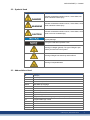
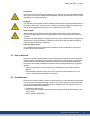
2.2 Symbols Used
Symbol
Indication
DANGER
WARNING
CAUTION
Indicates a hazardous situation which, if not avoided, will
result in death or serious injury.
Indicates a hazardous situation which, if not avoided, could
result in death or serious injury.
Indicates a hazardous situation which, if not avoided, could
result in minor or moderate injury.
Indicates situations which, if not avoided, could result in
property damage.
This symbol indicates important notes.
Warning of a danger (general). The type of danger is specified by the text next to the symbol.
Warning of danger from electricity and its effects.
Warning of suspended loads.
2.3 Abbreviations Used
Abbreviation Meaning
Cat
Category
DO
Drive object
DU
Data Unit
GSD
Device description file
GSDML
GSD Markup Language
HMI
Human machine interface
ID
Identifier
I/O
Input / Output
IRT
Isochronous Real-Time
LED
Light emitting diode
PAP
Programm Ablauf Protokoll (program sequence protocol)
PLC
Programmable logic control
PNU
Parameter number
RT
Real-Time
STW
Control word
ZSW
Status word
Kollmorgen | December 2014
7
AKD PROFINET | 2 General
8
Kollmorgen | December 2014
AKD PROFINET | 3 Safety
3 Safety
3.1 Safety Instructions
10
3.2 You should pay attention to this
10
3.3 Use as directed
11
3.4 Prohibited use
11
Kollmorgen | December 2014
9
AKD PROFINET | 3 Safety
3.1 Safety Instructions
3.2 You should pay attention to this
This section helps you to recognize and avoid dangers to people and objects.
Read the documentation!
Read the available documentation before installation and commissioning. Improper handling
of the drive can cause harm to people or damage to property. The operator of systems using
the AKD must require that all personnel who work with the drive read and understand the
manual before using the drive.
Install the drive as described in the Installation Manual. The wiring for the analog setpoint
input and the positioning interface, as shown in the wiring diagram in the Installation Manual,
is not required.
Check Firmware Revision!
Check the Firmware Revision of the product. This number is the link between your product
and the fieldbus manual. It must match the Firmware Revision on the manual's cover page.
Perform a risk assessment!
The manufacturer of the machine must generate a risk assessment for the machine, and take
appropriate measures to ensure that unforeseen movements cannot cause injury or damage
to any person or property. Additional requirements on specialist staff may also result from the
risk assessment.
Observe remote-controlled machine behaviour!
Electronic equipment is basically not failure-proof. The user is responsible for ensuring that,
in the event of a failure of the drive, the drive is set to a state that is safe for both machinery
and personnel, for instance with the aid of a mechanical brake.
Drives with PROFINET are remote-controlled machines. They can start to move at any time
without previous warning. Take appropriate measures to ensure that the operating and service personnel is aware of this danger.
Implement appropriate protective measures to ensure that any unintended start-up of the
machines cannot result in dangerous situations for personnel or machinery. Software limitswitches are not a substitute for the hardware limit-switches in the machine.
Specialist staff required!
Only properly qualified personnel are permitted to perform such tasks as setup and programming. Qualified specialist staff are persons who are familiar with the installation, setup
and programming of drives and who bring their relevant minimum qualifications to bear on
their duties:
l
l
l
Installation: only by electrically qualified personnel.
Setup : only by qualified personnel with extensive knowledge of electrical engineering
and drive technology
Programming: Software developers, project-planners
The qualified personnel must know and observe ISO 12100 / IEC 60364 / IEC 60664 and
national accident prevention regulations.
Observe electrostatically sensitive components!
The drives contain electrostatically sensitive components which may be damaged by incorrect handling. Electrostatically discharge your body before touching the drive. Avoid contact
with highly insulating materials (artificial fabrics, plastic film etc.). Place the drive on a conductive surface.
10
Kollmorgen | December 2014
AKD PROFINET | 3 Safety
Hot surface!
Drives may have hot surfaces during operation. The heat sink can reach temperatures above
80°C. Risk of minor burns! Measure the temperature, and wait until the heat sink has cooled
down below 40 °C before touching it.
Earthing!
It is vital that you ensure that the drive is safely earthed to the PE (protective earth) busbar in
the switch cabinet. Risk of electric shock. Without low-resistance earthing no personal protection can be guaranteed and there is a risk of death from electric shock.
High voltages!
Wait at least 7 minutes after disconnecting the drive from the main supply power before
touching potentially live sections of the equipment (such as contacts) or removing any connections.
Capacitors can have dangerous voltages present up to seven minutes after switching off the
supply power. Always measure the voltage in the DC bus link and wait until the voltage is
below 60 V before handling components.
Never modify the drive!
It is not allowed to modify the drive without permission by the manufacturer. Opening the
housing causes loss of warranty.
3.3 Use as directed
Drives are components that are built into electrical plants or machines and can only be operated as integral components of these plants or machines. The manufacturer of the machine
used with a drive must generate a risk assessment for the machine and take appropriate
measures to ensure that unforeseen movements cannot cause personnel injury or property
damage.
l
l
Observe the chapters "Use as directed” and "Prohibited use" in the AKD Installation
Manual.
The PROFINET interface serves only for the connection of the AKD directly or via a
switch to a network with PROFINET connectivity.
3.4 Prohibited use
Other use than that described in chapter “Use as directed” is not intended and can lead to personnel injuries and equipment damage. The drive may not be used with a machine that does
not comply with appropriate national directives or standards. The use of the drive in the following environments is also prohibited:
l
l
l
potentially explosive areas
environments with corrosive and/or electrically conductive acids, alkaline solutions, oils,
vapors, dusts
ships or offshore applications
Kollmorgen | December 2014
11
AKD PROFINET | 4 Installation and Setup
4 Installation and Setup
12
4.1 Important Instructions
13
4.2 PROFINET Onboard
14
4.3 Guide to Setup
15
4.4 Configure IP Address parameters
16
4.5 Setup Step 7
19
4.6 Parameter Configuration with PROFIdrive over PROFINET IO
22
Kollmorgen | December 2014
AKD PROFINET | 4 Installation and Setup
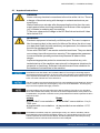
4.1 Important Instructions
DANGER
Never undo any electrical connections to the drive while it is live. There is
a danger of electrical arcing with damage to contacts and serious personal injury.
Wait at least seven minutes after disconnecting the drive from the main
supply power before touching potentially live sections of the equipment
(e.g. contacts) or undoing any connections.
To be sure, measure the voltage in the DC Bus link and wait until it has
fallen below 60 V.
WARNING
Electronic equipment is basically not failure-proof. The user is responsible for ensuring that, in the event of a failure of the drive, the drive is set
to a state that is safe for both machinery and personnel, for instance with
the aid of a mechanical brake.
Drives with PROFINET are remote-controlled machines. They can start to
move at any time without previous warning. Take appropriate measures
to ensure that the operating and service personnel is aware of this
danger.
Implement appropriate protective measures to ensure that any unintended start-up of the machines cannot result in dangerous situations for
personnel or machinery. Software limit-switches are not a substitute for
the hardware limit-switches in the machine.
Install the drive as described in the Installation Manual. The wiring for the analog setpoint
input and the positioning interface, as shown in the wiring diagram in the Installation Manual,
is not required. Never break any of the electrical connections to the drive while it is live. This
action can result in destruction of the electronics.
The drive's status must be monitored by the PLC to acknowledge critical situations. Wire the
FAULT contact in series into the emergency stop circuit of the installation. The emergency
stop circuit must operate the supply contactor.
It is permissible to use the setup software to alter the settings of the drive. Any other alterations will invalidate the warranty. Because of the internal representation of the position-control parameters, the position controller can only be operated if the final limit speed of the drive
does not exceed:
rotary
at sinusoidal² commutation:
7500 rpm
at trapezoidal commutation:
12000 rpm.
linear
at sinusoidal² commutation: 4 m/s
at trapezoidal commutation: 6.25
m/s
All the data on resolution, step size, positioning accuracy etc. refer to calculatory values.
Non-linearities in the mechanism (backlash, flexing, etc.) are not taken into account. If the
final limit speed of the motor must be altered, then all the parameters that were previously
entered for position control and motion blocks must be adapted.
Kollmorgen | December 2014
13
AKD PROFINET | 4 Installation and Setup
4.2 PROFINET Onboard
Connection to the PROFINET Network via X11.
Connect the service interface (X11) of the drive to an Ethernet interface on the PROFINET
Master directly or via a network switch, while the supply to the equipment is switched
off.
Confirm that the link LED on the AKD (the green LED on the RJ45 connector) and on your
Master or Switch are both illuminated. If both lights are illuminated, then you have a good
electrical connection.
PROFINET RT and WorkBench can operate simultaneously if a switch is used.
4.2.1 LED functions
The communication status is indicated by the built-in LEDs.
Connector LED#
Name
Function
X11
LED1 IN port Link ON = active, OFF= not active
LED2
RUN
ON = running, OFF = not running
4.2.2 Connection technology
You can connect to the PROFINET network using RJ-45 connectors. Use standard Cat. 5
Ethernet cables for either connection configuration.
4.2.3 Network Connection Examples
14
Kollmorgen | December 2014
AKD PROFINET | 4 Installation and Setup
4.3 Guide to Setup
Only professional personnel with extensive knowledge of control and drive technology are
allowed to setup the drive.
CAUTION
Drives with PROFINET are remote-controlled machines. They can start to
move at any time without previous warning. Take appropriate measures
to ensure that the operating and service personnel is aware of this
danger.
Implement appropriate protective measures to ensure that any unintended start-up of the machines cannot result in dangerous situations for
personnel or machinery. Software limit-switches are not a substitute for
the hardware limit-switches in the machine.
1. Check assembly/installation. Check that all the safety instructions in the product manual
for the drive and this manual have been observed and implemented. Check station
address and baud rate setting.
2. Connect PC,start WorkBench. Use the setup software WorkBench to set the parameters
for the drive.
3. Setup basic functions. Start up the basic functions of the drive and optimize the current,
speed and position controllers. This section of the setup is described in the in the online
help of the setup software.
4. Save parameters. When the parameters have been optimized, save them in the drive.
Kollmorgen | December 2014
15
AKD PROFINET | 4 Installation and Setup
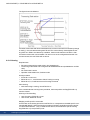
4.4 Configure IP Address parameters
Start the SIMATIC Manager. To assign a new IP address, go to PLC->Edit Ethernet Node:
In the next dialog window, click on browse in the Ethernet node group and look for all
PROFINET devices in your network:
Select the AKD and click ok. If you have several AKD’s in your network, you can also use
the MAC address to filter one PROFINET device.
To be sure, that the intended device is selected, you can click the “Flash” Button in the dialog. The display of selected device will flash as long as this function is active.
The MAC address can be found on the label of the AKD.
16
Kollmorgen | December 2014
AKD PROFINET | 4 Installation and Setup
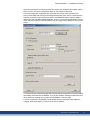
Select the radio button Use IP parameters: then enter a new IP address and subnet mask to
AKD. Click the Assign IP Configuration button for the change to take effect
Use the same popup to change the device name at this time by entering a name in the
Device Name fields and clicking on the Assign Name button. Each device connected to the
same IO connection must have a unique name. The PROFINET device name for AKD is
derived from the AKD DRV.NAME parameter. The PLC, which acts as PROFINET IO-Controller. will use the Device Name as address and can change the IP address for each Device
Name.
You will usually see a status message that indicates that the change was successful and the
AKD display will show the new address. If you receive a failure message, make sure that no
IO connection is currently running, then retry the address or name change.
A current connection of WorkBench to AKD will be disconnected when the IP address is
changed. When this happens, reconnect to the new IP address.
Kollmorgen | December 2014
17
AKD PROFINET | 4 Installation and Setup
4.4.1 Dependency Service channel (WorkBench) and PROFINET
WorkBench and PROFINET use the same IP communication channel to communicate with
the drive so changing the IP address has implications for both interfaces.
There are several options for assigning the IP address for WorkBench and PROFINET as
described in the AKD User Guide:
l
l
l
DHCP, AutoIP
Static IP addressing
o Via rotary switches (Address area 192.168.0.xx)
o Via ASCII commands IP.ADDRESS, IP.SUBNET. IP.GATEWAY
PROFINET Devices (only): DCP
Once you have changed the IP address via DCP (e.g. through the steps above), the IP.* parameters stored in the drive are overwritten. Should you need to use DHCP or static IP addressing later, you must use WorkBench to set, the IP.MODE to something other than 1. See AKD
User Guide for details on the mode you would like to use.
4.4.2 Reset of IP Address parameters
If the AKD can not be found in the network, as a last resort, reset all IP address parameters
to their default values.
This is done by setting the rotary switches to 0 and holding the B1 button longer than 5
seconds. After this, the current IP address setting will be lost and the IP address is restored
to default settings (after power cycle):
If rotary switches are zero, the DHCP and AutoIP is enabled.
If rotary switches are not zero, the static IP address is 192.168.0.xx (xx rotary switches) and
subnet mask 255.255.255.0.
18
Kollmorgen | December 2014
AKD PROFINET | 4 Installation and Setup
4.5 Setup Step 7
1. Start the SIMATIC Manager.
2. Open the hardware manager (double click on Hardware).
3. Go to Options and click "Install GSD Files". Here also the GSDML files for PROFINET
devices can be installed.:
Kollmorgen | December 2014
19
AKD PROFINET | 4 Installation and Setup
4. Browse for the latest AKD GSDML file and click on install:
5. The AKD GSDML file is installed now and can be found in the SIMATIC hardware catalog.
Open PROFINET I/O->Additional Fieldbus Devices->Drives->AKD
6. Click on the AKD device (not a telegram) and connect it to the PLC (drag and drop)
20
Kollmorgen | December 2014
AKD PROFINET | 4 Installation and Setup
7. Now configure the telegram, for example telegram 7 for use in position mode.
Drag and drop telegram 7 into slot 1.
8. Double click on the PROFINET network (line which connects PLC and AKD) and configure the update time. Click OK for closing this window.
9. Save and compile the hardware configuration.
Kollmorgen | December 2014
21
AKD PROFINET | 4 Installation and Setup
4.6 Parameter Configuration with PROFIdrive over PROFINET IO
The AKD is defined as an I/O Device in PROFINET IO. A PLC or other IO-Controller establishes a connection via a so called application relations (AR). Within this AR, different profiles like PROFIdrive, PROFIsafe etc. can be used for the communication. The PROFIdrive
profile, which AKD supports, is defined as Application Process Identifier (API) 0x3A00.
Within the AR, further addressing needs to done. PROFINET IO divides each device in so
called slots and subslots. Sub 0 refers to the device itself and returns all generic data like
vendor name, software and hardware version. The subslots within the device can be used
with different real and virtual modules. Each module a functional component, which for
example can be a digital I/O or Telegram with Position values.
AKD provides several virtual modules, which can be used in Slot 1 and are used for the real
time data exchange.
For read or write parameters to or from the AKD, the global base mode parameter access can
be used (see PROFIdrive chapter 8.6). The parameter manager is accessed through Slot 1
and a non real time channel needs to be used for this purpose. The AKD supports the record
data 47, which is used to address the Parameter numbers (PNUs).
Base mode parameter access shows the construction of the telegram:
The following PROFIdrive services are supported:
l
l
l
l
22
Single parameter value request
Multiple parameter value request
Single parameter change request
Multiple parameter change request
Kollmorgen | December 2014
AKD PROFINET | 4 Installation and Setup
Record data fields
The table shows the structure and the supported fields in the AKD for a parameter request.
Field
Request reference
Data type
Unsigned8
Values
0x00 reserved
Comment
0x01 – 0xFF
Response ID
Unsigned8
0x01 Request parameter (+)
0x02 Change parameter (+)
0x81 Request parameter (-)
0x82 Change parameter (-)
Axis / DO-ID
Unsigned8
0x00
No. of Parameters
Unsigned8
0x01.. 0x27
Attribute
Unsigned8
0x00 reserved
one Axis
0x10 Value
0x20 Description
No. of Elements
Unsigned8
0x01.. 0xEA Quantity
Parameter number
Unsigned16 0x0001 .. 0xFFFF PNU
Subindex
Unsigned16 0x0000 .. 0xFFFE
4.6.1 Parameter configuration
Kollmorgen | December 2014
23
AKD PROFINET | 4 Installation and Setup
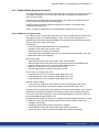
4.6.2 Example for writing the operation mode
For writing the operation mode an acyclic change parameter value request needs to be send
from the IO-Controller/Supervisor to the AKD.
If the user wants to write e.g. the operation mode to position mode (DRV.OPMODE 2) over
PROFINET, the PNU 930 needs to be written with value 0x0002. The PROFIdrive base parameter access (see "Position Units" (➜ p. 43)) describes the procedure.
Change parameter request (Operation mode):
Byte (dec) Value (hex)
0
0x05
Description
Request reference: e.g. 5
1
0x02
Request ID: Change parameters
2
0x00
Axis: 0 (the AKD parameter manager)
3
0x01
No of Parameter: 1
4
0x10
Attribute: Value
5
0x01
No. of Elements
6
0x03
PNU: 930 Operation mode
7
0xA2
8
0x00
9
0x00
10
0x42
Format: Word
11
0x01
No of Values: 1
12
0x00
Operation mode
13
0x02
Subindex: 0
The AKD answers with a positive response without values:
Byte (dec) Value (hex)
0
0x05
24
Description
Request Ref. mirrored: e.g. 5
1
0x02
Response ID: Change parameters
2
0x00
Axis: 0 (the AKD parameter manager)
3
0x01
No of Parameter: 1
4
0x00
Format
5
0x00
No. of Values 0
Kollmorgen | December 2014
AKD PROFINET | 5 PROFINET IO
5 PROFINET IO
5.1 Introduction
26
5.2 Restrictions and requirements
26
Kollmorgen | December 2014
25
AKD PROFINET | 5 PROFINET IO
5.1 Introduction
PROFINET IO is a real time protocol based on Ethernet. It is used as high level network for
industrial automation applications. PROFINET IO is very similar to PROFIbus and focuses
on the data exchange for programmable controller.
A PROFINET IO network consists of following devices:
l
l
l
IO controller: This is typically the PLC, which controls the whole application.
IO device: a decentralized IO device (e.g. drive, encoder, sensor), which is controlled by
the IO controller.
IO supervisor: HMI (human machine interface) or PC for diagnostic purposes or commissioning.
The real time channel (RT) is used for IO data and alarm mechanism. In PROFINET IO RT
(conformance class A and B), the RT data is transferred via a prioritized Ethernet frame. No
special hardware is required. Due to this prioritization a cycle time < 10ms can be achieved.
l
PROFINET IO IRT is used for higher timing requirements. Cycle times < 1ms is possible,
but also special hardware for IO Devices and switches are required.
All diagnostic and configuration data is transferred via the non real time channel (NRT). The
well known UDP protocol is used for this purpose. Anyhow, no timing determinism can be
guaranteed and typical the cycle times can be > 100ms.
5.2 Restrictions and requirements
5.2.1 Conformance Classes
AKD support Conformance Classes A and B. This means PROFIdrive parameters can be
configured over the PROFINET network, fault can be delivered and cyclic data channel functions. However, the synchronization between axes can not take place since it is a part of
Conformance Class C.
5.2.2 Cycle time of RT data
AKD fastest cycle time for the PROFINET cyclic data is 8 milliseconds.
5.2.3 Connector
PROFINET network connector in the AKD is the same RJ45 connector used for the service
functions. This connector is numbered as X11 on the AKD’s top panel.
5.2.4 Network topology
AKD can be connected as an I/O device on the PROFINET network in two manners:
1. As the last node in the network (since AKD has only one connector) in a line topology
2. As another node on the network in star topology (using a switch)
26
Kollmorgen | December 2014
AKD PROFINET | 6 PROFIDRIVE over PROFINET IO
6 PROFIDRIVE over PROFINET IO
6.1 Introduction
28
6.2 AKD as Drive Object (DO)
29
6.3 General State Machine
30
6.4 Control word bits (STW1)
31
6.5 Status word bits (ZSW1)
33
6.6 Supported PNU's
34
6.7 Signals
35
6.8 Telegram configuration
35
6.9 Velocity Mode (Application class 1)
36
6.10 Position Mode (Application class 3)
37
6.11 I/O Telegrams
41
6.12 Units
43
6.13 Alarms
44
6.14 Fault
44
6.15 ASCII configuration
45
Kollmorgen | December 2014
27
AKD PROFINET | 6 PROFIDRIVE over PROFINET IO
6.1 Introduction
The AKD supports the PROFIdrive profile for accessing and configuring standard and manufacture parameters via PROFINET IO to start/stop/configuring motion control tasks.
The profile defines as main element the Drive Object (DO), which is controlling the motion
task related parameters. It is important to understand that PROFIdrive is only a user profile,
which can be used with PROFINET IO.
Note that the AKD supports all mandatory functionality of the PROFIdrive profile, but naturally not all optional functionality. This chapter describes the supported optional elements.
28
Kollmorgen | December 2014
AKD PROFINET | 6 PROFIDRIVE over PROFINET IO
6.2 AKD as Drive Object (DO)
The drive object contains the following items:
l
l
l
General state machine
Axis control task
Parameter manager with parameter data base
Multiple communication channels are used for read/write data values over PROFINET IO.
The drive object can be accessed via:
l
l
l
l
Cyclic data exchange
Acyclic data exchange
Alarm queue (currently not supported)
Clock synchronous operation (currently not supported)
The cyclic data exchange includes the transmission/reception of data values like set point
values (e.g. Position set point, velocity set point or control word) and actual values (actual
position value, actual velocity or status word) between the master and the drive object.
These values are called IO data and are transferred in real time.
The acyclic data is used for configuring the drive, which typically is not time critical. Each
DO has an own parameter manager, which handles the access. The non real time channel is
used for this in PROFINET IO.
The alarm queue is used for signaling the master an exception situations, which are generated through the state machine or the axis control task itself (not supported in AKD).
The clock synchronous operation requires PROFINET IRT (conformance class C), which is
currently not supported by the AKD.
Kollmorgen | December 2014
29
AKD PROFINET | 6 PROFIDRIVE over PROFINET IO
6.3 General State Machine
30
Kollmorgen | December 2014
AKD PROFINET | 6 PROFIDRIVE over PROFINET IO
6.4 Control word bits (STW1)
The S7 application must set the bits in control word 1 to go through the PROFIdrive standard
state machine to enable mode (complying with the PROFIdrive standard 6.3.2). Bits 0-3 control the state machine state.
The control word (STW1) defines the following general functions:
General Control Word Bits
Bit Num- Description
ber
0
STW1 on/off
Comment
ON / OFF.
1
STW1 no coast stop
The drive will not coast stop if this bit is set.
2
STW1 no quick stop
The drive will not execute quick stop if this bit is set.
3
STW1 enable operation The drive will enable and execute command if all preconditions are set.
7
Fault acknowledge
Set this bit to reset faults in the drive.
Control by PLC
When not set no command will be accepted from the
PLC.
10
In velocity mode:
STW1 Special bits (Velocity mode)
Bit Num- Description
Comment
ber
4
Enable ramp generator Use DRV.ACC and DRV.DEC.
of the drive
5
Unfreeze the ramp gen- If frozen, the drive stays at current velocity without
erator in the drive
continuing to ramp up or down.
6
Enable set point
The drive accepts set point from the master. If this bit
is not set, the velocity will be 0.
8
Jog 1 on/off
The drive runs up/brakes along the ramp to jogging
setpoint 1/standstill.
Prerequisite: Operation is enabled, drive is in standstill and STW1 bit 4, 5, 6 = 0.
9
Jog 2 on/off
The drive runs up/brakes along the ramp to jogging
setpoint 2/standstill.
Prerequisite: Operation is enabled, drive is in standstill and STW1 bit 4, 5, 6 = 0.
Device specific
Not implemented.
11-15
Control word 1 must also set bits 4,5,6 (for speed control – in velocity operation mode) to
enable ramp generator and bit 10 to set the drive to be controlled by the PLC.
Bit 7 is used to acknowledge fault. The AKD will clear the fault and go automatically to S1
state after a fault is cleared.
The optional jog bits 8 and 9 can be used for the jogging functionility in velocity mode. PNU
1004 and 1005 define the jogging setpoints 1 and 2.
Kollmorgen | December 2014
31
AKD PROFINET | 6 PROFIDRIVE over PROFINET IO
In position mode:
STW1 Special bits (Position mode)
Bit Num- Name
Description
ber
4
Do Not Reject Travers- A traversing task is activated using the positive siging Task
nal edge at bit 6.
5
No Intermediate Stop
Traversing task can be interrupted and continued.
6
Activate Traversing
Task
Positive signal edge enables a traversing task.
8
Jog 1 on/off
The drive runs up/brakes along the ramp to jogging
setpoint 1/standstill.
Prerequisite: Operation is enabled, drive is in standstill and STW1 bit 4, 5, 6 = 0.
9
Jog 2 on/off
The drive runs up/brakes along the ramp to jogging
setpoint 2/standstill.
Prerequisite: Operation is enabled, drive is in standstill and STW1 bit 4, 5, 6 = 0.
11
Start Homing Procedure Homing mode is active. If this bit is cleared, the homing is aborted and the drive stops.
12
Real Time Jogging
Jogging data taken from MDI_ACC, MDI_DEC,
MDI_VELOCITY.
13
Real Time Jogging Direction
0: Clockwise 1: Counterclockwise
Device-specific
Not implemented.
14-15
The optional jog bits 8 and 9 can be used for the jogging functionility in position mode. PNU
1004 and 1005 define the jogging setpoints 1 and 2.
32
Kollmorgen | December 2014
AKD PROFINET | 6 PROFIDRIVE over PROFINET IO
6.5 Status word bits (ZSW1)
All status word1 bits are implemented according to the PROFIdrive standard.
For application class 1 (speed control) and 3 (position mode) all mandatory bits are implemented.
The status word (ZSW1) defines the following functions:
General Status Word Bits
Bit Number Description
0
ZSW1 drive ready to switch on
Comment
Ready To Switch On /Not Ready To
Switch On.
1
ZSW1 drive ready to operate
Ready To Operate / Not Ready To Operate.
2
ZSW1 operation enabled
Operation Enabled (drive follows velocity
set point) / Operation Disabled.
3
Fault present
A fault is present in the drive.
4
Coast stop not activated
No coast stop is executed.
5
Quick stop not activated
No quick stop is executed.
6
Switching on inhibited
7
Warning present
9
Control requested by the master
In velocity mode:
ZSW1 Special bits (Velocity mode)
Bit Number Description
8
Velocity error within range
10
11-15
Comment
Target velocity reached
Device specific
Not Implemented.
In position mode:
ZSW1 Special bits (Position mode)
Bit Number Name
8
Following error in range
Description
Error window (PL.ERR and
PL.ERRWTHRESH).
10
Target position reached
DRV.MOTIONSTAT Bit 11( Motion task
target position has been reached).
11
Home position set
DRV.MOTIONSTAT Bit 1 & 2 (Homing finished).
12
Traversing Task acknowledgment
On positive edge, traversing task acknowledged or set point accepted.
13
Drive stopped
14
Motion task active
DRV.MOTIONSTAT Bit 0 (Motion task
active/inactive)
15
Device specific
Not implemented
Axis is not moving
Kollmorgen | December 2014
33
AKD PROFINET | 6 PROFIDRIVE over PROFINET IO
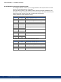
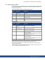
6.6 Supported PNU's
List of all supported PROFIdrive PNU's
The table mentions all supported PROFIdrive specific parameters. The access needs to be
done via base mode parameter access described in "Parameter Configuration with
PROFIdrive over PROFINET IO" (➜ p. 22).
PNU
915
Name
DO IO Data configuring
(set point telegram)
Data type Description
Array of U16
916
DO IO Data configuring
(actual value telegram)
Array of U16
922
Telegram selection
923
List of all parameters for
signals
930
Operating mode
U16
944
Fault message counter
U16
947
Fault number
Array of U16 All active faults.
964
Drive Unit Identification
Array of U16 Indices 0 – 4
965
Profile identification number
975
DO identification
U16
980 to 989 Number list of defined
parameter
The PROFIdrive telegram used for
the IO connection can be configured.
Array of U16 All supported signals and their corresponding PNU's.
Array of U16
1002
No. of singleturn bits
U16
Scaling of singleturn part in signal
MDI_TARPOS
1004
Jog v1
S16
Jogging set point 1
1005
Jog v2
S16
Sogging set point 2
1006
Jog Acc
U16
Jogging acceleration. Uses the
acceleration ramp of velocity loop.
1007
Jog Dec
U16
Jogging deceleration. Uses the
deceleration ramp of velocity loop.
1008
Acceleration scaling
U16
Scaling factor for acceleration and
deceleration.
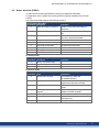
List of all manufacturer specific PNU's
The table shows all manufacture specific signals. All supported PROFIdrive and manufacture specific signals can be mapped into telegram 0 (dynamic telegram configuration).
PNU
1
Name
STW1
Data type
U16
Description
I/O control word
2
ZSW1
U16
I/O status word
5
NSOLL_A
S16
Velocity set point value
6
NIST_A
S16
Velocity actual value
32
SATZANW
U16
Motion task selection
33
AKTSATZ
U16
Actual motion task running
52
ITIST_GLATT
U16
Active Current (torque)
Supported Formats:
34
Format
0x41
0x42 0x43
Data type
Byte
Word Dword
Kollmorgen | December 2014
AKD PROFINET | 6 PROFIDRIVE over PROFINET IO
6.7 Signals
MDI_MOD
Bit
Description
0
0: Relative Positioning
1: Absolute Positioning
1 to 15
Reserved
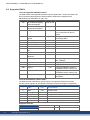
6.8 Telegram configuration
The telegram configuration is made according to the PROFIdrive standard. The PROFIdrive
parameters used in the configuration are: P922, P923, P915, P916 (see PROFIdrive profile,
page 110). The following PROFIdrive signals are changing the corresponding AKD signals:
Signal No.
1
Signal name
Control word 1
PROFIdrive signal name
STW1
AKD signal
Control word 1
2
Status word 1
ZSW1
Status word 1
5
Speed A
NSOLL_A
VL.CMD
6
Speed actual value
NIST_A
VL.FB
32
Traversing block selection
SATZANW
MT.MOVE
33
Actual traversing block
AKTSATZ
MT.PARAMS
34
MDI target position
MDI_TARPOS
MT.P*
35
MDI velocity
MDI_VELOCITY
MT.V*
36
MDI acceleration
MDI_ACC
MT.ACC*
37
MDI deceleration
MDI_DEC
MT.DEC*
38
MDI mode
MDI_MOD
MT.CNTL*
52
Active current (torque)
ITIST_GLATT
IL.FB
100
Homing distance
HOME_DIST
HOME.DIST
101
Motion task feedrate
MT_FEEDRATE
MT.FEEDRATE
102
Current Loop
IL_CMD_FIELDBUS
IL.CMD
103
Homing Mode
HOME_MODE
HOME.MODE
*Attention: The PROFIdrive signals are not mapped 1:1 to the AKD signals. The unit conversion for PROFIdrive needs to be used.
Either the predefined standard telegrams can be used for accessing the signals or a free mapping can be used with telegram 0.
The signals are also available in the PNU list. Each signal can be read/write with the same
PNU number. For instance, signal “Speed actual value” is also available with PNU 6.
Kollmorgen | December 2014
35
AKD PROFINET | 6 PROFIDRIVE over PROFINET IO
6.9 Velocity Mode (Application class 1)
In this mode, the drive is controlled via a primary set point (speed set point). The speed control is completely in the drive controller.
The field bus is merely the transmission medium between the automation system and the
drive controller. The Cyclic Data Exchange Communication Service is used.
Example
This example demonstrates enabling the drive and executing motion in velocity mode using
standard telegram 1. This means that the master needs to send 32 bits (16 control word and
16 velocity command) and read back 32 bits (16 status word and 16 velocity feedback)
1. Send control word bits as follows to move the state machine to S1:
0000_0100_0111_0000. Velocity command can be zero (it is ignored at this phase)
2. Send control word bits as follows to move the state machine to S2:
0000_0100_0111_0110. Velocity command can be zero (it is ignored at this phase)
3. Send control word bits as follows to move the state machine to S3:
0000_0100_0111_0111. Velocity command can be zero (it is ignored at this phase)
4. Send control word bits as follows to move the state machine to S4 and enable the drive:
0000_0100_0111_1111. Velocity command is used now, set it to 0x00A3 (1 rps)
36
Kollmorgen | December 2014
AKD PROFINET | 6 PROFIDRIVE over PROFINET IO
6.10 Position Mode (Application class 3)
In this application class the Drive Object (DO) provides a closed position control loop with its
own position interpolation. The motion tasks, which are configured by MT parameters in
AKD, can be accessed.
In PROFIdrive two different submodes are possible, which allow the controlling device to
access motion task parameters via I/O messaging.
Furthermore the general state machine of the drive Axis Object is extended to start/configure/stop a motion task.
“ONLY” in state S4 („Operational“), the extended state machine can be accessed.
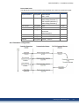
6.10.1 Submode „Program mode“
The „Program mode“ can be used to start/switch to a specific predefined motion task via I/O
messaging. Telegram 7 ("Standard telegram 7" (➜ p. 41)) is used for this purpose. For
addressing the motion task signal „SATZANW“ is used. With signal „AKTSATZ“ the actual
running motion task number can be read.
Requirements:
l
l
l
l
l
Drive axis state machine needs to be in S4 („Operational“)
Operation mode needs to be „Position mode“
Standard telegram 7 needs to be configured
Axis needs to be homed (ZSW1 Bit 11 set, See also Status word bits (ZSW1) (➜ p. 33))
Motion task needs to be configured
Start a motion task:
l
l
l
l
l
Set SATZANW to the motion task number, which shall be started
Set STW1 Bit 4 and 5 to true (Do not reject traversing task and no intermediate stop)
Set STW1 Bit 6 from zero to one, the motion task will be activated
ZSW1 Bit 13 will be set to one when the drive is moving
after the target position is reached, ZSW 1 Bit 10 is set
Abort or error in executing motion task:
l
l
l
If the following error is not in tolerance range, ZSW1 Bit 8 is set
If the following error is not in tolerance range, ZSW1 Bit 8 is set
If the following error is not in tolerance range, ZSW1 Bit 8 is set
Warning or Fault handling:
l
l
case of warning, ZSW1 Bit 7 is set (See also Status word bits (ZSW1) (➜ p. 33))
case of fault, ZSW1 Bit 3 is set (See also Status word bits (ZSW1) (➜ p. 33))
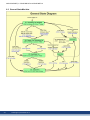
The figure on the next page shows the extension of the general state diagram of DO. Also the
optional jog functionality is supported. The homing procedure can be achieved through bit
STW1 Bit 11 (See also Homing (➜ p. 40)). After an intermediate stop, the motion task can
be activated again through STW1 Bit 5 set.
If the general state machine of the DO is in “Operational” and the standard telegram 7 is used
to configure a motion task, the following sequence can be used to start a motion task:
l
l
l
l
Configure a motion task
Change the general state machine to S4 (Drive is enabled)
Set SATZANW to the motion task number, which needs to be started
Used STW1 Bit 4,5 and 6 to start the motiontask. BIT 6 needs to be an edge
Kollmorgen | December 2014
37
AKD PROFINET | 6 PROFIDRIVE over PROFINET IO
The extension of the general state diagram of DO:
6.10.2 Submode „Manual data input (MDI)“
The "manual data input" mode can be used to run a motion task directly configured through
IO data. Telegram 9 is used for this purpose and defines the motion task specific signals like
acceleration (MID_ACC), deceleration (MID_DEC), velocity (MDI_VEL) and target position
(MDI_TAR_POS). With setting bit 15 in signal “SATZANW”, the MDI mode can be activated.
Requirements:
l
l
l
l
Drive axis state machine needs to be in S4 („Operational“).
Operation mode needs to be „Position mode“.
Standard telegram 9 needs to be configured.
Axis needs to be homed (ZSW1 Bit 11 set, See also Status word bits (ZSW1) (➜ p. 33).
Run a motion task:
l
l
l
l
l
l
38
Set bit 15 in SATZANW to 1
Configure all setpoint value in telegram 9 like MDI_ACC, MDI_DEC, MDI_MOD etc..
Set STW1 Bits 4 and 5 to true (Do not reject traversing task and no intermediate stop).
Set STW1 Bit 6 from zero to one, the motion task will be loaded.
ZSW1 Bit 12 is set to one, when the drive has started the new motion task.
ZSW1 Bit 13 will be set to 1 when the drive is moving after the target position is reached,
ZSW 1 Bit 10 is set.
Kollmorgen | December 2014
AKD PROFINET | 6 PROFIDRIVE over PROFINET IO
The extension of the state diagram for mdi mode:
The activation of a new motion task (or traversing task), is done through a hand shake
algorithm. After setting the “Activate traversing task” bit 6 in STW1, the signals MDI_
TARPOS, MDI_VELOCITY, MDI_ACC, MDI_DEC and MDI_MOD with their current values
are loaded into the drive. The “Traversing Task Acknowledgment” bit 12 in ZSW1 indicates
the point in time, when the motion task is starting execution.
Kollmorgen | December 2014
39
AKD PROFINET | 6 PROFIDRIVE over PROFINET IO
The figure shows the behavior:
If another motion task shall be executed before the current motion task has finished (“Change
on the fly”), the “Activate traversing task” Bit in STW1 can be directly cleared (after the setting of Bit 12 in ZSW1 was detected). In addition, the drive will clear Bit 12 in ZSW1. After
this another motion task can be loaded. If an error occurs or the configured motion task can
not be executed, bit 12 in ZSW1 will not be set.
6.10.3 Homing
Requirements:
l
l
l
l
Drive axis state machine needs to be in S4 („Operational“)
The homing mode needs to be configured via HOME.MODE 1001 (available also via PNU
1001).
No motion task is active
Operation mode needs to be „Position mode“
Home procedure:
l
l
l
STW1 Bit 11 set to one
ZSW1 Bit 10, 11 ,13 will be set to false if homing is running
ZSW1 Bit 10,11,13 will be set to true if homing is finished
Abort homing:
l
while the homing is running, clear STW1 Bit 11
If the controller aborts a running home procedure, the home position set flag (ZSW1 Bit 11)
remains cleared.
Warning or Fault handling:
l
l
case of warning, ZSW1 Bit 7 is set
case of fault, ZSW1 Bit 3 is set
Mapping to AKD specific commands:
An activation of the homing procedure via STW1 Bit 11 corresponds to the AKD specific command HOME.MOVE. When the homing procedure is finished, the AKD set the bits 2 and bit
4 in DRV.MOTIONSTAT. „Only“ if these two bits are set, the PROFIdrive specific homing
flag ZSW1 Bit 11 (home position) is set.
40
Kollmorgen | December 2014
AKD PROFINET | 6 PROFIDRIVE over PROFINET IO
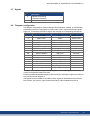
6.11 I/O Telegrams
6.11.1 Telegram 0
Telegram 0 is used for the free mapping of PROFIdrive signals into the PROFINET I/O data.
With PNU 922 the telegram can be configured. PNU915 defines then set point signals and
PNU 916 the actual value signals.
Limitations: The number and kind of signals, which can be mapped, are depending on the configuration of your PROFINET master. The length for input and output values in the IO communication is given through telegram configuration in slot 1.
6.11.2 Standard telegram 1
Typically used for application class 1 (velocity mode). The set point velocity value can be directly controlled by an PROFINET master.
IO Data Number Set point
1
STW1
2
NSOLL_A
Actual values
ZSW1
NIST_A
6.11.3 Standard telegram 7
Typically used for application class 3 (position mode). Predefined motion tasks can be selected directly via IO data.
IO Data Number Set point
1
STW1
2
SATZANW
Actual values
ZSW1
AKTSATZ
6.11.4 Standard telegram 9
Typically used for application class 3 (position mode). A motion task can be directly configured via IO data.
IO Data Number Set point
1
STW1
Actual values
ZSW1
2
SATZANW
AKTSATZ
3
STW2
ZSW2
4
MDI_TARPOS
XIST_A
5
6
XIST_A
MDI_VELOCITY
7
8
MDI_ACC
9
MDI_DEC
10
MDI_MOD
Kollmorgen | December 2014
41
AKD PROFINET | 6 PROFIDRIVE over PROFINET IO
6.11.5 Manufacturer specific telegram 350
Telegram 350 is typically used for application class 1 (velocity mode). Additonally to telegram 1 the actual current value can be monitored in the IO data.
IO Data number Set point
1
STW1
2
NSOLL_A
3
Actual values
ZSW1
NIST_A
ITIST_GLATT
6.11.6 Manufacturer specific telegram 351
Telegram 351 is typically used for application class 1 (velocity mode). Additonally to telegram 1 the actual current value and position value can be monitored in the IO data.
IO Data number Set point
1
STW1
2
NSOLL_A
3
Actual values
ZSW1
NIST_A
ITIST_GLATT
4, 5
XIST_A
6.11.7 Manufacturer specific telegram 352
IO Data Number Set point
1
STW1
Actual values
ZSW1
2
SATZANW
AKTSATZ
3
STW2
ZSW2
4
MDI_TARPOS
XIST_A
5
6
XIST_A
MDI_VELOCITY
7
8
MDI_ACC
9
MDI_DEC
10
MDI_MOD
11
HOME_DIST
12
6.11.8 Manufacturer specific telegram 353
IO Data Number Set point
1
STW1
2
SATZANW
AKTSATZ
3
STW2
ZSW2
4
MDI_TARPOS
XIST_A
5
6
XIST_A
MDI_VELOCITY
7
8
MDI_ACC
9
MDI_DEC
10
MDI_MOD
11
HOME_DIST
12
42
Actual values
ZSW1
Kollmorgen | December 2014
AKD PROFINET | 6 PROFIDRIVE over PROFINET IO
IO Data Number Set point
13
HOME_MODE
Actual values
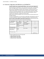
6.12 Units
6.12.1 Velocity units
Velocity units are normalized according to X2 data normalization of PROFIdrive (hence "set
normalization bit x" => 2^x = 100% velocity).
In velocity mode:
The AKD uses x=15 and 100% is the maximum velocity of the AKD hence 12000 rpm. Thus
the velocity units are 2^15 = 12000 rpm.
E.g. if the S7 wants to set a velocity of 60 rpm in the cyclic channel in needs to convert:
(60 / 12000) * 2^15 = 163
In position mode:
For signal MDI_VELOCITY x = 32 and 100% is the maximum velocity of the AKD hence
12000 rpm. Thus a value of 2^32 for MDI_VELOCITY is equal 12000 rpm.
6.12.2 Position Units
The signal MDI_TARPOS a 32 signed position value. In the default configuration, the resolution per revolution is 2^16 (65536) counts. The number of singleturn bits (default 16) can
be changed through PNU 1002.
6.12.3 Acc-/Deceleration Units
The acceleration signal MDI_ACC and MDI_DEC are normalized in the X2 format (x = 16 is
equal to 100% and means 50,000,000 rpm /sec). Acceleration and deceleration can be
scaled using PNU1008 as follows
PNU1008 value rpm/sec
1
763 rpm/sec
2
1536 rpm/sec
...
...
65536
50,000,000 rpm /sec
6.12.4 Current units
Current units are normalized according to N2 data normalization of PROFIdrive
(2^14 = 100%). The AKD’s 100% is the maximum current of the AKD hence DRV.IPEAK.
Thus current units are 2^14 = DRV.IPEAK.
Example: for 3 A AKD, if the S7 reads a current value of -182 Arms in the cyclic channel from
the AKD, it will need to execute the conversion
(9 / 2^14) * (-182) = -0.1 Arms
Kollmorgen | December 2014
43
AKD PROFINET | 6 PROFIDRIVE over PROFINET IO
6.13 Alarms
Not implemented yet.
6.14 Fault
All actual faults can be described as a so called “Fault situation”. This fault situation can be
read from the fault buffer with PNU 947. A fault situation can have up to 8 different faults. An
unacknowledged is indicated by ZSW1 bit 3 (fault present). With acknowledging the actual
fault situation, the fault numbers are shifted to the acknowledged faults section (shift of 8 positions in the fault buffer (PNU 947)). Each time a fault situation is generated, a fault message
counter is incremented (PNU 944). With reading the value of the fault message counter
before and after the read process of the Fault buffer (947), the user can be sure that no other
fault situation has been occurred in the meanwhile if these values are equal.
The fault buffer PNU 947 store up to 8 fault situation. Each fault situation can have up to 8
fault numbers.
44
Kollmorgen | December 2014
AKD PROFINET | 6 PROFIDRIVE over PROFINET IO
6.15 ASCII configuration
Use the following AKD parameters to configure behavior.
FBUS.PARAM01: Reads the configured telegram (PNU922 in Supported PNU's (➜ p. 34)).
FBUS.PARAM02 Bit 0:
Value of 1: Fault 702 (Fieldbus communication lost) is triggered if the PROFINET
master changes states from RUN to STOP.
Value of 0: No fault is triggered if the PROFINET master changes states from RUN to
STOP.
PN.STW1: Returns the control word (signal STW1) written by the PROFINET master.
PN.ZSW1: Returns the status word (signal ZSW1) sent by the AKD to the PROFINET master.
Kollmorgen | December 2014
45
AKD PROFINET | 7 Sample Projects
7 Sample Projects
7.1 Sample S7 Project
46
Kollmorgen | December 2014
47
AKD PROFINET | 7 Sample Projects
7.1 Sample S7 Project
7.1.1 Introduction
On our website www.kollmorgen.com, you can find an STEP 7 sample project which
provides a PROFINET network with an IO-controller and the AKD as IO-device.
The sample project can help you to learn:
l
l
l
how to enable the drive
how to write/read a parameter via the acyclic channel
how the cyclic data exchange is done
The sample project is based on a CPU-315 controller, which easily can be changed to
another PROFINET supporting controller.
Kollmorgen does not guarantee correctness.
7.1.2 Project description
You will find in the STEP 7 program three organization blocks that need to be implemented.
l
l
l
OB1, which is used for the main program and is a cyclic process.
OB40, which is used for any process alarm (needs to be implemented the CPU from
STOP to RUN).
OB82, which catches the diagnostic alarms.
Two variable tables are included
l
l
TG1_IO_DATA can be used to control easily the IO data between the plc and the AKD
PARAMETER_ACCESS table is used for read/write PNU’s via PROFINET
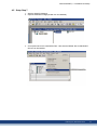
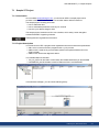
In the hardware manager, you can see the following setup :
Kollmorgen | December 2014
47
AKD PROFINET | 7 Sample Projects
7.1.3 Getting started
1. To use this example project, open the SIMATIC manager and retrieve the project zip file
(SimaticManager->File->Retrieve).
2. After the project is loaded, go to the hardware manager and check the communication
setup. If no AKD GSDML file is installed, the hardware manager will install it from the project. If there is already an installation of the GSDML file, this step is not required.
3. Check the communication setup for your system in the hardware manager and adapt it to
your settings.
The initial setup for AKD is a static IP Address and an IO cycle time of 128 ms.
Change the IP addresses for AKD and the PLC to your specific setup.
4. Verify the hardware configuration in the hardware manager and click the “save and compile” button in your configuration.
Verify the process-image input and output area of your plc and verify that is
greater than 256 byte or change the input/output start address of the AKD telegram you choose. By default, the input is copied to start address 256 and the output to start address 256.
5. In this example, the AKD shall be used in velocity mode. Therefore the “Standard Telegram 1” (PROFIdrive) is chosen. The signals control word, speed set point as well as
status word and speed actual value are mapped to the IO-Data.
The AKD has to be set to DRV.OPMODE 1 for this operation.
.
48
Kollmorgen | December 2014
AKD PROFINET | 7 Sample Projects
7.1.4 Enable the drive and run in velocity mode
The general state machine of the PROFIdrive ("General State Machine" (➜ p. 30)) needs to
be toggled to enable the drive. You can find in the variable table “TG1_IO_DATA” all necessary input and output parameters described bit-wise.
To enable the drive, write the following sequence in the control world:
1.
2.
3.
4.
QW 2#0000_0100_0000_0000 -> Remote control over field bus
QW 2#0000_0100_0000_0110 -> Go to S2 (Switch on inhibited)
QW 2#0000_0100_0000_1110 -> Go to S3 (Switched on)
QW 2#0000_0100_0000_1111 -> Go to S4 (Operational)
The drive is enabled, if the corresponding bits in the status word are set. TIP: If WorkBench
is connected, you will see the drive is enabled.
Now the set point velocity can be set. In the example (see variable table) the value is QW
258 is 0xA3 (60 rpm ("Units" (➜ p. 43))). To start the motion, set Bit 4, 5 and 6 (enable ramp
generator, unfreeze ramp generator and enable new set point).
Kollmorgen | December 2014
49
AKD PROFINET | 8 Record of Document Revisions
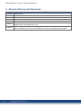
8 Record of Document Revisions
50
Revision
A, 10/2011
Remarks
Launch version
B, 03/2012
Jog mode added, mdi submode description extended
C, 08/2012
Manufacturer specific telegram 351
D, 05/2013
Corrections, formatting acc. to 82079
E, 12/2013
Added bit 14 for position mode in Status word bits (ZSW1) (➜ p. 33).
F, 05/2014
Added Signal No. 100 and 101 to Telegram configuration (➜ p. 35). Added Manufacturer specific
telegram 352 to I/O Telegrams (➜ p. 41).
G, 12/2014
Manufacturer specific telegram 353 (➜ p. 42) added. Signal number 102 and 103 added to Telegram configuration (➜ p. 35). Acc-/Deceleration Units (➜ p. 43) scaling information added.
Kollmorgen | December 2014
AKD PROFINET | 9 Index
Telegram configuration
9 Index
U
Units
Use as directed
A
Abbreviations
35
43
11
7
C
Control word
31
D
Document Revisions
Drive Object
50
29
F
Fault
44
G
General State Machine
GSDML
30
19
I
I/O Telegrams
41
P
Parameter Configuration
Position Mode
PROFIDRIVE
PROFINET Hardware
Prohibited Use
22
37
27
14
11
S
Safety Instructions
General
Setup Step 7
Signals
Status word
Submode „Manual data input (MDI)“
Submode „Program mode“
Supported PNU's
Symbols used
10
19
35
33
38
37
34
7
T
Telegram 0
telegram 1
telegram 350
telegram 351
telegram 7
telegram 9
41
41
42
42
41
41
Kollmorgen | December 2014
51
AKD PROFINET | 9 Index
This page intentionally left blank.
52
Kollmorgen | December 2014
About KOLLMORGEN Kollmorgen is a leading provider of motion systems and components for machine builders. Through worldclass knowledge in motion, industry-leading quality and deep expertise in linking and integrating standard and
custom products, Kollmorgen delivers breakthrough solutions that are unmatched in performance, reliability
and ease-of-use, giving machine builders an irrefutable marketplace advantage. For assistance with your application needs, visit www.kollmorgen.com or contact us at:
North America
KOLLMORGEN
203A West Rock Road
Radford, VA 24141 USA
Europe
KOLLMORGEN Europe GmbH
Pempelfurtstraße 1
40880 Ratingen, Germany
Asia
KOLLMORGEN
Rm 2205, Scitech Tower, China
22 Jianguomen Wai Street
Web:
Mail:
Tel.: Fax: Web:
Mail:
Tel.: Fax: Web: www.kollmorgen.com
Mail: [email protected]
Tel.: +86 - 400 666 1802
Fax: +86 - 10 6515 0263
www.kollmorgen.com
[email protected]
+1 - 540 - 633 - 3545
+1 - 540 - 639 - 4162
www.kollmorgen.com
[email protected]
+49 - 2102 - 9394 - 0
+49 - 2102 - 9394 - 3155