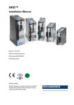
1
Kollmorgen Automation Suite
KAS v2.6 Getting Started
Edition December 2012, Built on Tuesday, December 18, 2012
Valid for Software Revision 2.6
Keep all manuals as a product component during the life span of the product.
Pass all manuals to future users / owners of the product.
Getting Started | Trademarks and Copyrights
Trademarks and Copyrights
Copyrights
Copyright © 2009-12 Kollmorgen™
Information in this document is subject to change without notice. The software
package described in this document is furnished under a license agreement or nondisclosure agreement. The software may be used or copied only in accordance with
the terms of those agreements.
This document is the intellectual property of Kollmorgen™ and contains proprietary
and confidential information. The reproduction, modification, translation or disclosure
to third parties of this document (in whole or in part) is strictly prohibited without the
prior written permission of Kollmorgen™.
Trademarks
KAS and AKD are registered trademarks of Kollmorgen™.
SERVOSTAR is a registered trademark of Kollmorgen™.
Kollmorgen™ is part of the Danaher Motion company.
Windows® is a registered trademark of Microsoft Corporation
EnDat is a registered trademark of Dr. Johannes Heidenhain GmbH.
EtherCAT® is registered trademark of Ethercat Technology Group.
PLCopen is an independent association providing efficiency in industrial automation.
INtime® is a registered trademark of TenAsys® Corporation.
Codemeter is a registered trademark of WIBU-Systems AG.
Kollmorgen Automation Suite is based on the work of:
l
Apache log4net library for output logging (distributed under the Apache License).
l
bsdtar and libarchive2, a utility and library to create and read several different archive
formats (distributed under the terms of the BSD License).
l
bzip2.dll, a data compression library (distributed under the terms of the BSD
License).
l
Curl software library
l
DockPanel Suite, a docking library for .Net Windows Forms (distributed under the MIT
License).
l
FileHelpers library to import/export data from fixed length or delimited files.
l
l
GNU gzip1 (www.gnu.org) is used by the PDMM (distributed under the terms of the
GNU General Public License http://www.gnu.org/licenses/gpl-2.0.html).
GNU Tar2 (www.gnu.org) is used by the PDMM (distributed under the terms of the
GNU General Public License http://www.gnu.org/licenses/gpl-2.0.html).
l
jQuery File Tree, a file browser plugin (distributed under the MIT License).
l
JsonCpp software (distributed under the MIT License – see http://jsoncpp.sourceforge.net/LICENSE for terms)
l
Mongoose software (distributed under the MIT License)
l
MVVM Light Toolkit components for Model – View –ViewModel patterns with Windows Presentation Foundation (distributed under the MIT License).
l
Qwt project (distributed under the terms of the GNU Lesser General Public License)
1Copyright (C) 2007 Free Software Foundation, Inc. Copyright (C) 1993 Jean-loup Gailly. This is free soft-
ware. You may redistribute copies of it under the terms of the GNU General Public License <http://www.gnu.org/licenses/gpl.html>. There is NO WARRANTY, to the extent permitted by law. Written by Jean-loup Gailly.
2Copyright (C) 2007 Free Software Foundation, Inc. License GPLv2+: GNU GPL version 2 or later
<http://gnu.org/licenses/gpl.html> This is free software: you are free to change and redistribute it. There is NO
WARRANTY, to the extent permitted by law. Written by John Gilmore and Jay Fenlason.
2
Kollmorgen™ | May 2012
Getting Started | Disclaimer
l
U-Boot, a universal boot loader is used by the AKD-PDMM (distributed under the
terms of the GNU General Public License, http://www.gnu.org/licenses/gpl-2.0.html).
The U-Boot source files, copyright notice, and readme are available on the distribution disk that is included with the AKD-PDMM.
l
ZedGraph class library, user control, and web control for .NET (distributed under the
LGPL License).
l
Zlib software library
l
Zlib1.dll, a data compression library (distributed under the terms of the BSD License).
All other product and brand names listed in this document may be trademarks or
registered trademarks of their respective owners.
Disclaimer
The information in this document (Version 2.6 published on 12/18/2012) is believed
to be accurate and reliable at the time of its release. Notwithstanding the foregoing,
Kollmorgen assumes no responsibility for any damage or loss resulting from the use
of this help, and expressly disclaims any liability or damages for loss of data, loss of
use, and property damage of any kind, direct, incidental or consequential, in regard
to or arising out of the performance or form of the materials presented herein or in
any software programs that accompany this document.
All timing diagrams, whether produced by Kollmorgen or included by courtesy of the
PLCopen organization, are provided with accuracy on a best-effort basis with no
warranty, explicit or implied, by Kollmorgen. The user releases Kollmorgen from any
liability arising out of the use of these timing diagrams.
Kollmorgen™ | May 2012
3
This page intentionally left blank.
4
Kollmorgen™ | May 2012
Getting Started | Table of Contents
Table of Contents
Kollmorgen Automation Suite
1
KAS v2.6 Getting Started
1
Trademarks and Copyrights
2
Copyrights
2
Trademarks
2
Disclaimer
3
Table of Contents
5
1
7
Introduction
1.1
Related Documents
7
1.2
Alerts and Warnings
7
2
System Overview
9
2.1
Software Packages
9
2.2
Hardware Components
3
Installing KAS IDE
10
11
3.1
System Requirements
11
3.2
Download
11
3.3
Installation Procedure
11
3.3.1
4
User Data
Installing KAS Run Time
12
13
4.1
System Requirements
13
4.2
Installation Procedure
13
Installing Hardware
15
5
5.1
Installing EtherCAT Motion Bus
17
5.2
Installing AKD Drive
17
5.3
Installing AKM Motor
17
5.4
HMI - Graphic Operator Interface
17
5.5
Controller - Industrial PC (IPC)
17
5.5.1
Deploying IPC standard image
19
5.5.2
Configuring INtime
19
5.6
EtherCAT Motion Bus
21
5.7
Remote Input/Output - I/O Terminal
22
5.7.1
Installing Bus Terminals on mounting rails
23
Kollmorgen™ | May 2012
5
Getting Started | Table of Contents
5.7.2
24
5.8
Installing AKD Drive
25
5.9
Installing AKM Motor
25
Updating Firmware
27
6
Check AKD PDMM Drive Firmware
27
Download AKD PDMM Drive Firmware
27
6.1
27
7
AKD PDMM Firmware Update
Installing Kollmorgen Visualization Builder
29
7.1
Download
29
7.2
Installation Procedure
29
Finalizing Installation
35
8
8.1
Testing Installation
35
8.2
Saving Installation
35
9
6
Connection Details
8.2.1
Backup IPC Image
35
8.2.2
Enhanced Write Filter
40
8.2.3
Restore IPC backup Image
42
Troubleshooting KAS
43
Global Support Contacts
45
Kollmorgen™ | May 2012
Getting Started | 1 Introduction
1 Introduction
This guide covers the main following procedures to have your KAS system up and running:
l
Hardware Installation (Connection and Wiring)
Hardware details, connectors, system diagrams
l
Hardware Configuration
Basic configuration and settings needed to start the HW components
(HMI + Industrial PC + Fieldbus + I/O)
l
KAS IDE Installation
KAS software setup
1.1 Related Documents
In addition to this Guide, you need the following manuals to install KAS
Title
Description
AKD Quick Start
Contains all information needed to safely install and setup an AKD drive
AKD Installation Manual
Covers the most important points to install the drive hardware and software.
Provides instructions for basic drive setup and connection to a network
AKD EtherCAT Communication
Describes the installation, setup, and software protocol for the EtherCAT
AKD product series
1.2 Alerts and Warnings
When alert symbols are seen in a manual, be alert to the potential for personal injury.
Follow the recommended precautions and safe operating practices included with the alert
symbols. Safety notices in the manuals provide important information. Read and be familiar
with these instructions before attempting to install, operate, or perform maintenance. The
purpose of this section is to alert users to possible safety hazards associated with
equipments and the precautions that need to be taken to reduce the risk of personal injury
and damage to the equipment. Failure to observe these precautions could result in serious
bodily injury, damage to the equipment, or operational difficulty.
Directs attention to general precautions, which if not followed, could result in personal injury and/or equipment damage
CAUTION
Alerts you to potential physical danger or harm. Not following warning notices could result in personal injury
WARNING
NOTE
Provides important information to ensure a thorough understanding of product use.
Kollmorgen™ | May 2012
7
Getting Started | 1 Introduction
This page intentionally left blank.
8
Kollmorgen™ | May 2012
Getting Started | 2 System Overview
2 System Overview
Kollmorgen Automation Suite is a complete system solution. This includes a variety of
powerful software packages designed to give you complete control over your hardware.
2.1 Software Packages
Software
Description
KAS IDE
Provides you with all the necessary tools for designing, programming, configuring,
debugging and maintaining machine applications
KAS Runtime
The KAS Run Time engine includes a soft PLC and a motion controller
KVB (optional)
This application is optional and assists in designing an HMI panel
Do not install KAS IDE on the Kollmorgen PAC controllers. The two are not compatible.
Kollmorgen™ | May 2012
9
Getting Started | 2 System Overview
2.2 Hardware Components
The KAS system is build using the following hardware components.
10
Component
Name
Description
Industrial PC
AKC
Controls all the network devices (remote I/O, drives...) by managing the PLC and
motion engines
Remote I/O
AKT
Refers to the communication and acquisition of data between your automation
system and the outside world
HMI
AKI
This component provides an interface for controlling the KAS Runtime
Drive
AKD
Servo drives specifically designed with versatility, communications, and the power
to expand machine performance and increase integration speeds
Motor
AKM
The servo motor is an engine that can drive to different setpoint positions and
then maintains these in the sense of a control drive
Kollmorgen™ | May 2012
Getting Started | 3 Installing KAS IDE
3 Installing KAS IDE
3.1 System Requirements
KAS IDE minimum system requirements:
Requirement
Description
Operating System
Microsoft Windows XP (32-bit XP pro SP3 or above), Windows 7 (32 and 64-bit)
Processor type
Intel® Pentium® M or equivalent processor 1.5 GHz
Memory
512 MB RAM
Storage
1 GB hard drive or compact flash space
Display
WXGA+ (1440 x 900) or higher-resolution monitor with 24-bit color
Connectivity
1 Ethernet port 100Mbits/s or 1Gbits/s
1 RS-232 serial port is needed for some target devices
KAS IDE and KAS Simulator should not be installed on a Kollmorgen PAC. The IDE
and Simulator are for use on PCs only.
3.2 Download
The latest version of the Kollmorgen Automation Suite is available at www.kollmorgen.com.
3.3 Installation Procedure
How to proceed if you have a CD?
After inserting the installation CD, a web browser automatically displays the installation
start page.
If the installation start page does not automatically display, double-click on the file
Index.html file.
To start the installation of Kollmorgen Automation Suite, click the corresponding link and
confirm that you want to execute KAS-Setup.exe.
Follow the procedure below to proceed with the KAS IDE software installation.
Installation of the KAS IDE can require you to change your firewall setting. If you do
not have sufficient privileges to configure your firewall, you must stop the relevant
Windows Service.
Once KAS has finished downloading, complete the following installation steps:
1. Double-click the KAS-Setup.exe file to run the installation Wizard.
A Security Warning dialog displays as a result of security
certification. Do not be alarmed.
2. Click Run to start the installation Wizard.
3. While the setup is loading, wait for the setup splash screen to vanish after being displayed.
Kollmorgen™ | May 2012
11
Getting Started | 3 Installing KAS IDE
4. If a previous version of the KAS IDE is installed then an uninstall notice is displayed. The
previous version must be uninstalled before the installation can continue. All content of the
previous repository is deleted during the uninstall.
5. The following Welcome Wizard displays with the version and build number of the KAS IDE.
Click Next to continue.
6. Review the License Agreement and click "I Agree" to continue the installation.
You must accept the agreement to install Kollmorgen
Automation Suite.
7. Select the Development Environment installation type from the drop-down menu.
Installation
type
Description
Development
Environment
This kind of installation is typically used for creating and developing a new application.
When you need to install the KAS IDE and the KAS Runtime Simulator, you can select
Development Environment as the type of installation.
Run-time
Industrial PC
This installation is typically used when you have an industrial PC (IPC).
You are able to view and run your application. You need to install Kollmorgen Visualization
Builder and the KAS Runtime.
Kollmorgen Visualization Builder is specially designed to view and control your application.
The KAS Runtime only executes the application.
Custom
You can manually select the specific KAS components to install.
8. Click Next to access the destination folder.
9. Click Browse to specify a custom install directory or accept the recommended default location. When finished, click Install to continue.
Kollmorgen strongly recommends accepting the default
destination folder under C:\Program
Files\Kollmorgen\Kollmorgen Automation Suite\Kollmorgen
Automation Suite.
10. The software installation begins. Wait until the installation process is complete.
11. You are done; click Finish.
Adding the KAS IDE application as an exception in your firewall settings is
recommended to avoid security issues
3.3.1 User Data
User-generated data such as log files, project sources, field bus configurations, function
blocks, etc. are stored in the Windows User directory and are maintained between
installations. This applies to files on PACs, AKD PDMMs, as well as Simulator files.
12
Kollmorgen™ | May 2012
Getting Started | 4 Installing KAS Run Time
4 Installing KAS Run Time
The PAC controller comes with all the necessary software already installed (including KAS
Runtime). The image version is displayed on the background image of the desktop.
KAS Runtime is only supported with Kollmorgen controllers.
4.1 System Requirements
Operating System
The KAS Runtime is supported under XP embedded (XPe) for the industrial PC.
Recommended network environment
Only a Local Network connection can ensure the communicate between the KAS IDE and
the KAS Runtime.
The KAS IDE is not able to communicate to the KAS Runtime through NAT
connection.
Supported Kollmorgen Industrial KAS Runtime is compatible with AKC hardware models
PC
4.2 Installation Procedure
Install the KAS Runtime software.
1. Double-click the KAS-Setup.exe file to run the installation Wizard
2. Click Run to launch the setup wizard
3. Wait for the setup splash screen to vanish after being displayed
Figure 4-1: Setup splash screen
4. The welcome wizard appears and show you the version and build number, click Next to
continue the wizard
5. In the drop-down menu, choose the type of installation to deploy: Run-time Industrial PC
Figure 4-2: Install Run-time for Industrial PC
(See the different Types of Deployment in paragraph "Installing KAS IDE" on page 11)
6. Click Next to access the destination folder
7. Select where you want to install KAS
Kollmorgen™ | May 2012
13
Getting Started | 4 Installing KAS Run Time
Kollmorgen strongly recommends accepting the default destination folder under C:\Program
Files\Kollmorgen\Kollmorgen Automation Suite
8. Keep the name proposed for the Start Menu Folder and click the Install button to install
KAS
9. You have to wait until the end of the process
10. Wait until the installation is complete
If your Wibu-Key driver is not already installed, a reminder is displayed saying that the
WKRuntime.exe needs to be installed. If so, click OK.
11. Click Finish
You can now activate your license application (refer to § "Activating License").
The EWF filter must be activated on the IPC when everything is ready and must not
change anymore. If a significant change happens (like a new KAS version or
downloading a new application), the recommendation is to turn off the EWF filter,
make the change, and then reactivate it. For more details about this procedure, see
page 40
After the KAS Runtime installation, you have to restart the IPC.
14
Kollmorgen™ | May 2012
Getting Started | 5 Installing Hardware
5 Installing Hardware
Prior to have your motion application up and running, you first need to connect, wire and
configure all your hardware components.
The Getting Started guide contains procedures for installing and configuring hardware
components (HMI, PAC controllers, I/O Terminals, EtherCAT Motion Bus, AKD Drive, and
AKM Motor).
Figure 5-1: Connecting all the Hardware components
For extensive information about installing the different hardware components, see the
relevant documentation available on:
l
KollmorgenWeb site
l
KAS IDE online help (after it has been installed)
Links to installation instructions for hardware components can be found in the following
table.
Component
Installation
HMI (Human-Machine Interface)
Install the graphic operator interface
Install HMI
Controller
Install the Panel or Box Programmable Automation Control
(PAC)
Install Industrial PC
Kollmorgen™ | May 2012
15
Getting Started | 5 Installing Hardware
Component
Installation
EtherCAT Motion Bus
Set up EtherCAT Motion Bus Communication
See AKD™ EtherCAT Communication
I/O Terminal
Install the remote Input/Output Terminal
Install I/O Terminals
AKD Drive
Install the AKD Drive
See AKD Installation Manual
(and also AKD Quick Start)
AKM Motor
Install the AKM Motor
Mechanical and Electrical installation
Available in
http://www.kollmorgen.com/website/com/
eng/download/document/akm_deis.pdf
(pp 31-52)
Table 5-1: Kollmorgen Automation Suite Installation and Configuration
16
Kollmorgen™ | May 2012
Getting Started | 5 Installing Hardware
5.1 Installing EtherCAT Motion Bus
One EtherCAT master (e.g. PAC) has to be connected with all the slaves (drives and I/O
terminals) of your system. Please find all the details about the installation procedure for the
EtherCAT Motion Bus in the following deliverable AKD EtherCAT Communication
5.2 Installing AKD Drive
The official AKD firmware version is: 01-03-00-302
To install the AKD drive as well as the AKD GUI Views, refer to chapters 7 to 9 in the AKD
Installation Manual
5.3 Installing AKM Motor
To install rotary AKM Servomotors, refer to chapters 17 to 19 in: AKM Synchronous
Servomotors - Product Manual
5.4 HMI - Graphic Operator Interface
Please find in the table below the list of each HMI component available:
HMI part number
Description
AKI-CDF-MOD-06T-000
Graphical Display 5.7" TFT, 64k Colors, 16 F-Keys, 16 LEDs
AKI-CDF-MOD-10T-000
Graphical Display 10.4" TFT, 64k Colors, 22 F-Keys, 22 LED's
AKI-CDT-MOD-04T-000
Graphical Display 3.5" TFT, LCD, 64k Colors, Touch
AKI-CDT-MOD-06T-000
Graphical Display 5.7" TFT, LCD, 64k Colors, Touch
AKI-CDT-MOD-10T-000
Graphical Display 10.4" TFT, LCD, 64k Colors, Touch
AKI-CDT-MOD-15T-000
Graphical Display 15.1" TFT, LCD, 64k Colors, Touch
Tech. Manual
Table 5-2: List of KAS HMI
Please see the Kollmorgen website for specifications and Technical Manuals for more
information.
5.5 Controller - Industrial PC (IPC)
First connect the keyboard and the mouse to the IPC (as well as the monitor if it is not built
into the IPC) to be sure that the IPC correctly starts when it is powered by a supply voltage
of 24v (not necessarily provided).
The box PAC is equipped with a DVI port, as seen to the right.
DVI ports are backwards compatible for use with VGA monitors
when using a DVI-to-VGA adapter. The first time the PAC is
booted, an external monitor will only stay on for a brief time. The system needs to be
configured from the keyboard, depending on what is connected to the DVI port. Press the
keyboard combination shown below that matches your set-up. This configuration is
automatically saved.
DVI cable DVI-VGA adapter
CTRL-ALT-F4 CTRL-ALT-F1
Kollmorgen™ | May 2012
17
Getting Started | 5 Installing Hardware
How to recover when the monitor seems to be unplugged or switched off?
The problem is probably due to the internal graphical card configuration and the currently
known solution is the following:
l
Restart the IPC and press the F8 key to enter the advanced XP start-up mode
l
Select the VGA mode enable start-up option
l
Reboot the IPC and XP starts normally
l
Ignore Windows comments on the screen
l
Click the Start menu and select Settings then Control Panel
l
Click the System command to explore the hardware configuration of the computer
l
In the System Properties windows, select the Device Manager command in the Hardware
tab
l
In the Device Manager windows, expand the Display Adapters node
l
Check that two Graphic Controllers are displayed
l
Right-click on the first item and select the Uninstall command in the contextual menu
l
Reboot your IPC as requested to validate the modification
After the reboot operation, your IPC should now work normally.
To be sure that the modification has been done properly, explore again the hardware
configuration and compare it with the figure below.
One of the controllers must be deactivated (see red cross on its icon).
Please find in the table below the list of each IPC component available:
18
PAC part number
Description
AKC-PLC-C1-224-00N-00-000
Box Controller, Celeron 1.2GHz CPU, 2G RAM, 4G CF, 128KB
NVRAM
AKC-PLC-D2-224-00N-00-000
Box Controller, Dual Core 2.26GHz CPU, 2G RAM, 4G CF, 128KB
NVRAM
AKC-PNC-C1-224-10N-00-000
10" Panel Controller, Celeron 1.2GHz CPU, 2G RAM, 4G CF,
128KB NVRAM
AKC-PNC-C1-224-15N-00-000
15" Panel Controller, Celeron 1.2GHz CPU, 2G RAM, 4G CF,
128KB NVRAM
Kollmorgen™ | May 2012
Tech.
Manual
Getting Started | 5 Installing Hardware
PAC part number
Description
Tech.
Manual
AKC-PNC-D1-224-15N-00-000
15" Panel Controller, C2D 1.86GHz CPU, 2G RAM, 4G CF, 128KB
NVRAM
AKC-PNC-D1-224-17N-00-000
17" Panel Controller, C2D 1.86GHz CPU, 2G RAM, 4G CF, 128KB
NVRAM
AKC-RMC-D2-224-00N-00-000
Rackmount Controller, Dual Core 2.26GHz CPU, 2G RAM, 4G CF,
128KB NVRAM
Table 5-3: List of KAS PAC
5.5.1 Deploying IPC standard image
The next step is to deploy the standard image that contains INtime Software with the correct
settings for all the real-time part, as well as the EtherCAT option card settings. This step is
done by Kollmorgen.
5.5.2 Configuring INtime
To finalize the INtime software installation, some fine tuning still has to be performed as
follows:
1. Right-click on the INtime icon and select the INtime Configuration command in the contextual menu
2. Double-click the Miscellaneous icon
3. Select the Display Fault Management Dialog option
Kollmorgen™ | May 2012
19
Getting Started | 5 Installing Hardware
4. Click OK
5. In the INtime Configuration Panel, click on the Autoload icon
6. Enable the Hilscher Profibus CIF diver option, but disable the SpinDoctor and iWin32
options as shown below
7. Click OK
8. Restart your IPC for the changes to become effective
20
Kollmorgen™ | May 2012
Getting Started | 5 Installing Hardware
After these changes, INtime is now successfully configured to run on your IPC.
5.6 EtherCAT Motion Bus
One EtherCAT master (e.g. PAC) has to be connected with all the slaves (drives and I/O
terminals) of your system. Please find all the details about the installation procedure for the
EtherCAT Motion Bus in the following deliverable AKD™ EtherCAT Communication listed
in the list of References.
Kollmorgen™ | May 2012
21
Getting Started | 5 Installing Hardware
5.7 Remote Input/Output - I/O Terminal
Please find in the table below the list of each I/O component available.
I/O terminal part
number
Description
AKT-ECT-000-000
ETHERCAT Coupler
AKT-DNH-008-000
8 Channel Digital Input Module, 24Vdc 0.2ms
AKT-DN-008-000
8 Channel Digital Input Module, 24Vdc 3ms
AKT-DNH-004-000
4 Channel Digital Input Module, 24Vdc 0.2ms
AKT-DN-004-000
4 Channel Digital Input Module, 24Vdc 3ms
AKT-DT-008-000
8 Channel Digital Output Module, 24Vdc 0.5A
AKT-DT-004-000
4 Channel Digital Output Module, 24Vdc 0.5A
AKT-DT-2RT-000
2 Channel Relay Output Module, 250V AC 2.0A Rel.2NO Pot.-Free
AKT-AN-420-000
4 Channel Analog Input Module, 0-20mA
AKT-AN-410-000
4 Channel Analog Input Module, 0-10Vdc
AKT-AN-820-000
8 Channel Analog Input Module, 0-20mA
AKT-AN-810-000
8 Channel Analog Input Module, 0-10Vdc
AKT-AN-200-000
2 Channel Thermocouple Input Module
AKT-AN-400-000
4 Channel Thermocouple Input Module
AKT-AT-220-000
2 Channel Analog Output Module, 0-20mA
AKT-AT-420-000
4 Channel Analog Output Module, 0-20mA
AKT-AT-410-000
4 Channel Analog Output Module, 0-10Vdc
AKT-AT-820-000
8 Channel Analog Output Module, 0-20mA
AKT-AT-810-000
8 Channel Analog Output Module, 0-10Vdc
AKT-EM-000-000
End Module
AKT-IM-000-000
Isolation Module
AKT-PS-024-000
Power Supply, 24Vdc
AKT-PSF-024-000
Fused Power Supply with diagnostics, 24Vdc
Table 5-4: List of KAS I/O Terminals
22
Kollmorgen™ | May 2012
Tech.Manual
Getting Started | 5 Installing Hardware
5.7.1 Installing Bus Terminals on mounting rails
Bring the bus terminal system into a safe, powered down state before starting installation,
disassembly or wiring of the Bus Terminals!
5.7.1.1 Assembly
The Bus Coupler and Bus Terminals are attached to commercially available 35 mm
mounting rails (DIN rails according to EN 50022) by applying slight pressure:
1. First attach the Fieldbus Coupler to the mounting rail.
2. The Bus Terminals are now attached on the right-hand side of the Fieldbus Coupler. Join
the components with tongue and groove and push the terminals against the mounting rail,
until the lock clicks onto the mounting rail.
If the Terminals are clipped onto the mounting rail first and then pushed together without
tongue and groove, the connection is not operational! When correctly assembled, no significant gap is visible between the housings.
During the installation of the Bus Terminals, the locking mechanism of the terminals must
not come into conflict with the fixing bolts of the mounting rail.
5.7.1.2 Disassembly
Each terminal is secured by a lock on the mounting rail, which must be released for
disassembly:
1. Carefully pull the orange-colored lug approximately 1 cm out of the disassembled terminal,
until it protrudes loosely. The lock with the mounting rail is now released for this terminal,
and the terminal can be pulled from the mounting rail without excessive force.
2. Grasp the released terminal with thumb and index finger simultaneous at the upper and
lower grooved housing surfaces and pull the terminal away from the mounting rail.
5.7.1.3 Connections within a bus terminal block
The electric connections between the Bus Coupler and the Bus Terminals are automatically
realized by joining the components:
l
The six spring contacts of the Standard/Performance Coupler deal with the transfer of the
data and the supply of the Bus Terminal electronics.
l
The power contacts deal with the supply for the field electronics and thus represent a supply
rail within the bus terminal block. The power contacts are supplied via terminals on the Bus
Coupler.
During the design of a bus terminal block, the pin assignment of the individual Bus
Terminals must be taken account of, since some types (e.g. analog Bus Terminals or
digital 4-channel Bus Terminals) do not or not fully loop through the power
contacts.Power Feed Terminals (AKT-PS-024-000 or AKT-PSF-024-000) interrupt the
power contacts and thus represent the start of a new supply rail.
5.7.1.4 PE power contact
The power contact labeled PE can be used as a protective earth. For safety reasons this
contact mates first when plugging together, and can ground short-circuit currents of up to
125 A.
Note that, for reasons of electromagnetic compatibility, the PE contacts are capacitatively
coupled to the mounting rail. It can lead to incorrect results during insulation testing or to
damage on the terminal (e.g. disruptive discharge to the PE line during insulation testing
of a consumer with a nominal voltage of 230 V).
For insulation testing, disconnect the PE supply line at the Bus Coupler or the Power Feed
Terminal! In order to decouple further feed points for testing, these Power Feed Terminals
can be released and pulled at least 10 mm from the group of terminals.
Kollmorgen™ | May 2012
23
Getting Started | 5 Installing Hardware
The PE power contact must not be used for other potentials!
5.7.1.5 Wiring
Up to eight connections enable the connection of solid or finely stranded cables to the Bus
Terminals. The terminals are implemented in spring force technology. Connect the cables as
follows:
1. Open a spring-loaded terminal by slightly pushing with a screwdriver or a rod into the
square opening above the terminal.
2. The wire can now be inserted into the round terminal opening without any force.
3. The terminal closes automatically when the pressure is released, holding the wire securely
and permanently.
Analog sensors and actors must always be connected with shielded, twisted paired
wires.
5.7.2 Connection Details
24
Kollmorgen™ | May 2012
Getting Started | 5 Installing Hardware
5.8 Installing AKD Drive
To install the AKD drive as well as the AKD GUI Views, refer to chapters 7 to 9 in the
AKD™- Installation Manual
Drives Guide
Description
AKD Quick Start
Contains all information needed to safely install and setup
an AKD drive
AKD and AKD PDMM Installation Manual
Covers the most important points to install the drive
hardware and software
Provides instructions for basic drive setup and connection to
a network
AKD User Manual
Describes how to use your drive in common applications. It
also provides tips for maximizing your system performance
with the AKD
AKD Accessories Manual
Includes technical data and dimensional drawings of
accessories such as cables, brake resistors, and mains
supplies
AKD EtherCAT Manual
Describes the installation, setup, range of functions, and
software protocol for the EtherCAT AKD product series
AKD CANopen Communication
This manual includes setup information for the CAN
interface and describes the CANopen profile
AKD EtherNet/IP Communications Manual
This manual contains information for using an
AKD EtherNet/IP drive.
AKD EtherNet/IP with RSLogix Manual
This manual contains information for using an
AKD EtherNet/IP drive with RSLogix.
AKD Profinet Communication Manual
This manual contains information for using an AKD Profinet drive.
AKD SynqNet Communication Manual
This manual contains information for using an AKD SynqNet drive.
AKD HMI Modbus Communication Manual
This manual contains information on communication between an
AKD and HMI through Modbus.
S300 Reference Documentation
Kollmorgen website that gives access to all S300 manuals
Table 5-5: List of AKD Guides
5.9 Installing AKM Motor
To install rotary AKM Servomotors, refer to the following AKM deliverable:
l
Chapters 17 to 19 in: AKM™ Synchronous Servomotors - Product Manual
This manual can be downloaded at
http://www.kollmorgen.com/uploadedfiles/Files/Document/Motors_and_Drives_Overview_
Brochure.pdf
Kollmorgen™ | May 2012
25
Getting Started | 5 Installing Hardware
This page intentionally left blank.
26
Kollmorgen™ | May 2012
Getting Started | 6 Updating Firmware
6 Updating Firmware
Check the KAS software release notes to find the AKD PDMM firmware version that matches
with your KAS software version. The latest version of the firmware can be downloaded from
the Kollmorgen web site.
To ensure your installation is correct, you have to:
l
Check the current AKD drive firmware
l
Download the official version, if necessary
l
Update the firmware
Check AKD PDMM Drive Firmware
To check AKD PDMM Firmware with KAS IDE:
1. Create a new project
2. Set the controller type and IP address
3. In the Project Explorer, double-click the EtherCAT node to open the EtherCAT Devices
summary window
4. In the Devices tab, click the Scan Devices button
5. Choose the Create... option to map the physical device to a new device
6. If the version is not correct, continue following with the procedure below
7. Compile the project
8. Connect to the controller
9. Download the project to the controller
10. If the version is not correct, download the new firmware (click here) and follow with the next
procedure.
Download AKD PDMM Drive Firmware
Component
Download
AKD PDMM Drive FW - Version: AKD-M-MCEC-V01-08-00-003.i00
To upgrade AKD PDMM Firmware with KAS IDE, continue from the previous procedure as
follows:
1. In the EtherCAT Devices summary window, deactivate the Online Configuration Mode
2. Select the drives to be updated with the same firmware
(Note that the FW download is limited to 16 drives at a time)
3. Click Upgrade Firmware button
Give careful attention to any warning dialog that appears at this point. These warnings
usually include important information about preventing damage to the drives.
4. Browse to select the new AKD firmware file
5. Click Open to start the updating procedure
6.1 AKD PDMM Firmware Update
Based on the FoE protocol, the AKD PDMM Firmware can be downloaded as follows:
1. Scan the devices and make sure all devices are created
2. Compile the project
3. Connect to the controller
4. Download the project to the controller
5. Open the EtherCAT Devices summary form
Kollmorgen™ | May 2012
27
Getting Started | 6 Updating Firmware
6. Select the drives to be updated with the same firmware
7. Click the Upgrade Firmware button
Give careful attention to any warning dialog that appears at
this point. These warnings usually include important
information about preventing damage to the drives.
8. Browse to select the new AKD firmware file
9. Click Open to start the updating procedure
This procedure is not possible when applications are running
and when the drive is in Online Configuration Mode.
During the firmware download, the AKD Firmware Update window displays a progress bar
and the following messages are displayed:
l
Uploading firmware to the drive
During the download process, the drive LED displays [dL]. Additional codes may appear during the download; see 3.2 Display Codes for a description of codes related to the firmware
download.
l
Resetting the drive
l
Firmware update is complete
While the firmware is downloading to your drive, do not remove the 24V logic power. If
you remove the 24V logic power during a firmware download, a severe drive crash can
occur. If a crash occurs, the drive will restart in a special mode and prompt you to reload
the firmware.
28
Kollmorgen™ | May 2012
Getting Started | 7 Installing Kollmorgen Visualization Builder
7 Installing Kollmorgen Visualization Builder
KVB is an optional feature that is only included in some licenses.
Kollmorgen Visualization Builder allows you to design HMI panels running either on AKI or
panel PAC.
Kollmorgen Visualization Builder contains the two following installation packages:
l
Kollmorgen Visualization Builder(KVB IDE) for development PC
l
Visualizer RT(KVB RT) for AKI panel runtime
7.1 Download
Component
Download
Kollmorgen_Visualization_Builder_IDE_en-US_v1.20.545
302.9 MB
Visualizer RT (KVB RT) - Version 1.20
78 MB
7.2 Installation Procedure
The following programs must be installed before KVB can be installed:
l
Microsoft .NET Compact Framework 3.5
l
SQL Server Compact Edition
l
Microsoft Visual C++ 2008 - Redistributable Setup (vcredist_x86)
Once Kollmorgen Visualization Builder has finished downloading, complete the following
installation steps:
1. Double-click the Setup.exe file to run the installation Wizard
If KVB was already installed and you want to update to a
new version, then running NeoSetup.msi is enough.
2. Click Run to launch the setup wizard
3. If not already done, you are requested to install the Microsoft .NET Framework 3.5 Service Pack 1
Kollmorgen™ | May 2012
29
Getting Started | 7 Installing Kollmorgen Visualization Builder
Note: A reboot is required after installing this service pack
4. Click Next and accept License Agreement to start Kollmorgen Visualization Builder installation
5. Click Designer (corresponds to the Kollmorgen Visualization Builder application)
30
Kollmorgen™ | May 2012
Getting Started | 7 Installing Kollmorgen Visualization Builder
The Runtime (also named Visualizer RT) is dedicated to the PAC only
6. Choose your language and click Next
7. Select where you want to install Kollmorgen Visualization Builder and click Next
Kollmorgen strongly recommends accepting the default destination folder under C:\Program
Files\Kollmorgen\Kollmorgen Visualization Builder\
8. Click Install to start Kollmorgen Visualization Builder installation
Kollmorgen™ | May 2012
31
Getting Started | 7 Installing Kollmorgen Visualization Builder
9. Click Finish
When Kollmorgen Visualization Builder starts for the first time, a dialog box requests
a registration key. Entering this key provides unlimited access to all program
functionality and software updates.
32
Kollmorgen™ | May 2012
Getting Started | 7 Installing Kollmorgen Visualization Builder
Also, to allow the runtime (Visualizer RT) to run on the PAC, ensure the USB
hardware key is plugged in.
Kollmorgen™ | May 2012
33
Getting Started | 7 Installing Kollmorgen Visualization Builder
This page intentionally left blank.
34
Kollmorgen™ | May 2012
Getting Started | 8 Finalizing Installation
8 Finalizing Installation
To complete the KAS installation, you can optionally:
l
Test the system
l
Create a backup image
8.1 Testing Installation
To conclude your installation, the whole system has to be tested.
A test could be done with the standard Two-Axis Template that corresponds to a simple
application (refer to KAS 30 Minutes to Motion).
8.2 Saving Installation
This chapter defines how to:
l
Save the IPC image on a CompactFlash card (aka USB memory stick)
l
Prevents from files corruptions in the PC's CompactFlash memory
To prevent corruption and be able to quickly restore your IPC image, Acronics SW and
Microsoft Enhanced Write Filter (EWF) can be used. The procedure described below
explains how to use these proposed tools.
Acronis True Image software is not part of Kollmorgen Automation Suite. For more
details, refer to: www.acronis.com.
EWF software is included in Windows® XP Embedded. For more details, refer to:
msdn.microsoft.com/en-us/library/ms912915.aspx
8.2.1 Backup IPC Image
As soon as all the hardware has been tested and validated, you can proceed to a complete
backup on a CompactFlash card (aka USB memory stick) with the Acronis True Image
software.
8.2.1.1 Prepare the bootable USB Stick
You first need a USB Stick (with a minimum of 2GB capacity) to be prepared as follows:
l
Install HP USB Disk Format Storage Tool (HP_USB Boot_Utility.exe)
l
Create a folder for the system files
C:\Documents and Settings\Myname\My Documents\IPC Backup Files\HP_USB\DOS
Kollmorgen™ | May 2012
35
Getting Started | 8 Finalizing Installation
36
l
Copy the following system files in this folder
l
Insert the USB stick into the USB port of your computer
l
Launch the HP format tool program (HPUSBFW.EXE) from the installed directory
l
Under the device drop-down list, make sure that your USB stick is selected
l
Under the File system drop down list, select FAT32
l
In the Format options, choose to Create a DOS startup disk and select using DOS system
files located at:
Kollmorgen™ | May 2012
Getting Started | 8 Finalizing Installation
l
Specify the folder location created in step 2
l
Click the Start button to format as a Bootable device using DOS directory
l
Click the Close button once the operation is completed
l
Install Acronis True Image 11 on your IPC
l
Start Acronis True Image application
Kollmorgen™ | May 2012
37
Getting Started | 8 Finalizing Installation
l
38
Go to Management tool
Kollmorgen™ | May 2012
Getting Started | 8 Finalizing Installation
l
Create Bootable Rescue Media
8.2.1.2 Create the Backup
To the complete backup, proceed as follows:
l
Connect the keyboard and the mouse to the IPC (as well as the monitor if it is not built into
the IPC)
For more details, refer to paragraph "Controller - Industrial PC (IPC)" on page 17
l
Start your IPC
l
During startup press the F2 key to enter the setup
l
Set the priority by selecting the first boot device to look for the USB stick (you only need to do
it once)
l
Insert the USB stick into a free USB port
l
Reboot your IPC
l
Start Acronis True Image application
l
Select True Image Home
l
Select Backup
l
Select My Computer
l
Select what is to be backed up (i.e. Disk1: Volume C)
l
Exclude nothing (do not select any exclusions)
l
Select the store location: A: Removable drive/Image/FILENAME (modify with a meaningful
FILENAME)
l
Select Create a new full backup archive
l
Choose Compression level and set to the maximum
l
Add notes if desired
l
Store in file name xxxxx_Original (create a full backup)
l
Do not have to enter password
Kollmorgen™ | May 2012
39
Getting Started | 8 Finalizing Installation
l
Compression level: Max
l
Finally click Proceed
8.2.2 Enhanced Write Filter
The Enhanced Write Filter (EWF) provides write-protection to
the runtime image. All write requests are redirected to RAM
and the runtime image maintains the appearance of being
able to written to. When the EWF is active its icon is shown
in the system tray, as seen to the right. When the EWF is
disabled its system tray icon is a red slashed-circle
.
The EWF should be activated on the PAC once the system is running and is in a stable
condition. If a significant change is going to happen (such as a new KAS version or
downloading a new application) turn off the EWF filter, make the change, and then reactivate
the filter.
There are two ways to manage the EWF:
l
With the EwfWinDllcaller.exe application, located in C:\WINDOWS\system32. This is the preferred method. See "Enhanced Write Filter Operational Procedures Using the Application"
(see page 40) for more information.
l
From the command line interface. The command line offers more functions than the application but is recommended only for advanced users. See "Enhanced Write Filter Operational
Procedures using the command line" (see page 41) for more information.
8.2.2.1 Practical Applications
l
For the KAS Runtime installation, using the "commitanddisable" method (via either command line or the application) is strongly recommended. If some operations have been performed previously, the remaining memory will not be sufficient using another method.
l
For a New PLC application download, the ""Perform Small Changes on a Protected Volume"
(see page 42)" method is convenient because the usual PLC application does not exceed
10 MB.
8.2.2.2 Enhanced Write Filter Operational Procedures Using the Application
Protect the PAC Image with EWF
The EWF must be activated to protect a stable version of the PAC image from data
corruption.
1. Close all applications
2. Launch EwfWinDLLcaller.exe
3. Click the Enable button
You will receive a message about the Enable being successful.
40
Kollmorgen™ | May 2012
Getting Started | 8 Finalizing Installation
4. Restart the computer
The icon in the system tray is green.
Perform Changes on a Protected Volume
The EWF has to be disabled to perform changes on a PAC.
1. Close all applications.
2. Launch EwfWinDLLcaller.exe
3. Click on the Commitanddisable button
You will receive a message about the Disable being successful.
4. Restart the computer.
The icon in the system tray is a red slashed-circle.
After pressing the Commitanddisable button you must restart the computer. The EWF
is not fully disabled until the computer is restarted and making any changes to the
system in this state can be troublesome.
After changes are made to the system, the EWF should be re-enabled to protect the PAC
image. See "Protect the PAC Image with EWF" (see page 40).
8.2.2.3 Enhanced Write Filter Operational Procedures using the command line
Using the EWF from the command line should only be performed by advanced users.
Using the application is easier and more reliable.
Protect the PAC Image with EWF
The EWF must be activated to protect a stable version of the PAC image from data
corruption.
l
Execute: ewfmgr c: -enable
l
Reboot the PAC
To ensure that the command has been entered correctly, execute the DOS command shell
ewfmgr c: prior to rebooting the PAC. Check the field Boot Command, which should be set
to "ENABLE", as seen in the image below.
If several commands are executed, only the latest will take effect after the reboot. To
be sure about the latest command, execute the process described above.
Perform Changes on a Protected Volume
The EWF has to be disabled to perform changes on a PAC. After the changes are made the
EWF is re-enabled.
l
Execute: ewfmgr c: -commitanddisable
l
Restart the PAC
l
Perform the desired changes (program installation, files record, etc…)
l
Execute: ewfmgr c: -enable
l
Restart the PAC
Kollmorgen™ | May 2012
41
Getting Started | 8 Finalizing Installation
It is important to note that the maximum overlay size is a little more than 300 MB.
Windows runs out of memory and crashes if this available space is exceeded,
resulting in the error "Delayed Write Failed. Windows was unable to save all data for
the file". As a consequence, when making important changes or file copy actions, do
not forget to disable EWF first, and re-enable it when the operations are complete.
Perform Small Changes on a Protected Volume
To commit small changes without disabling and enabling EWF, a single command can be
executed with the DOS command:
l
Execute: ewfmgr c: -commit
l
Restart the PAC
8.2.3 Restore IPC backup Image
To restore the complete backup, proceed as follows:
42
l
Connect the keyboard and the mouse to the IPC (as well as the monitor if it is not built into
the IPC)
For more details, refer to paragraph "Controller - Industrial PC (IPC)" on page 17
l
Insert the bootable USB stick into a free USB port
l
Reboot your IPC
l
Start Acronis True Image application
l
Select Restore
l
Select the restored backup file on the USB stick (.tib file)
l
Choose Restoration Method
l
Restore whole Disks and partitions
l
Select both Volume C and Master Boot record (MBR)
l
Select the Destination of Disk 1
l
Select option yes, I want to delete all the partitions on the destination hard drive before
restoring
l
Then start the restore operation
Kollmorgen™ | May 2012
Getting Started | 9 Troubleshooting KAS
9 Troubleshooting KAS
Faults occur for a variety of reasons, depending on the conditions in your installation. The
causes of faults in multi-axis systems can be especially complex.
You can find more details in:
l
the Troubleshooting chapter in the online help
l
the FAQ section in MyKAS.kollmorgen.com Web site
Kollmorgen™ | May 2012
43
Getting Started | 9 Troubleshooting KAS
This page intentionally left blank.
44
Kollmorgen™ | May 2012
Global Support Contacts
North America
KOLLMORGEN
203A West Rock Road
Radford, VA 24141 USA
Europe
KOLLMORGEN Europe GmbH
Pempelfurtstraße 1
40880 Ratingen, Germany
Asia
KOLLMORGEN
Rm 2205, Scitech Tower, China
22 Jianguomen Wai Street
Web:
www.kollmorgen.com
Web:
www.kollmorgen.com
Web:
www.kollmorgen.com
Mail:
[email protected]
Mail:
[email protected]
Mail:
[email protected]
Tel.: +1 - 540 - 633 - 3545
Tel.: +49 - 2102 - 9394 - 0
Tel.: +86 - 400 666 1802
Fax: +1 - 540 - 639 - 4162
Fax: +49 - 2102 - 9394 - 3155
Fax: +86 - 10 6515 0263