1
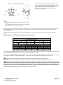
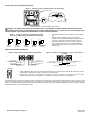
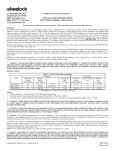
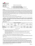
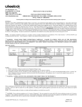
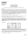
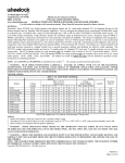
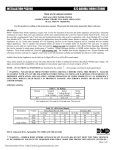
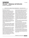
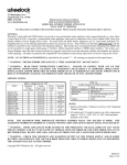
INSTALLATION INSTRUCTIONS
MULTI-CANDELA FOUR WIRE HORN STROBE APPLIANCES
(WALL MOUNT VERSION)
IMPORTANT – All audible and visual signaling appliances must be
installed in accordance with all applicable national and local fire alarm
codes and any other required regulatory agencies.
Series HS-MC Multi-Candela Horn Strobe provides four selectable
candela settings (15, 30, 75, 110). The HS-MC allows for independent
operation of the strobe circuit and the horn circuit. It is the ideal choice
for retrofit applications as well as new installations. The HS-MC
appliance is UL Listed under Standard 1971 for Signaling Appliances
for the Hearing Impaired and UL Standard 464 for Audible Signal
Appliances. The HS-MC is also ULC Listed under Standard CAN/ULCS526-02 for Visual Signaling Appliances and Standard CAN/ULCS525-99 for Audible Signaling Appliances for Fire Alarm Systems. It is
listed for indoor use only and can be mounted to double-gang, 4”
backbox, 100mm European backbox or MT-SUR-BOX surface
backbox (See wiring and mounting information). This appliance is
listed for wall mounting only. The HS-MC appliance uses a xenon
flashtube with solid state circuitry enclosed in a polycarbonate lens to
provide maximum visibility and reliability for effective visible signaling.
Siemens Series HS appliances provide a selectable continuous or
Code 3 horn tone and non-synchronized strobe when connected
directly to a Fire Alarm Control Panel (FACP). They can also provide a
synchronized Code 3 (or March Time) horn tone and synchronized
strobe when connected to a notification appliance circuit running the
Siemens sync protocol. HS appliances can be field set for High (HI),
medium (MED) dBA or low (LO) dBA sound output. .
NOTE: The Code 3 temporal pattern (1/2 second on, 1/2 second off,
1/2 second on, 1/2 second off, 1/2 second on, 1-1/2 off and repeat) is
specified by ANSI and NFPA 72 for standard emergency evacuation
signaling.
The Code 3 Horn should be used only for fire
evacuation signaling and not for any other purpose.
The HS-MC is designed for use with either filtered DC or unfiltered fullwave-rectified (FWR) input voltage. All inputs are polarized for
compatibility with standard reverse polarity supervision of circuit wiring
by an FACP.
NOTE: All Canadian Installations should be in accordance with the
Canadian Standard for the Installation of Fire Alarm Systems –
CAN/ULC-S524-01 and Canadian Electrical Code, Part 1. Final
acceptance is subject to authorities having jurisdiction (AHJ).
NFPA 72/ANSI 117.1 conform to ADAAG Equivalent Facilitation
Guidelines in using fewer, higher intensity strobes within the same
protected area.
NOTE: Refer to P/N 315-096363 for the maximum number of
appliances on a single notification appliance circuit.
SPECIFICATIONS:
Model*
HS-MC
Description
Continuous Horn
Code 3 Horn or
March Time**
Table 1: UL/ULC Listed Models and Ratings
Operating Voltage (Special Application)
Voltage Range Per
Per UL 1971
CAN/ULC-S526-02
(VDC/VRMS)
(VDC/VRMS)
16.0-33.0
20.0-31.0
*Available in red and white.
Volume
Low
Medium
High
Low
Medium
High
Strobe
Candela
(cd)
15/30/75/110
Table 2: dBA Sound Output for 24VDC Models
Reverberant Per UL 464
Anechoic dBA @ 10 Ft. Per CAN/ULC-S525-99
16.0VDC
24VDC
33.0VDC
20.0VDC
24VDC
31.0VDC
80
83
86
88
90
91
85
88
91
93
95
97
88
91
93
97
99
100
75
79
82
88
90
91
80
84
86
93
95
97
84
87
89
97
99
100
**Available in sync mode only.
Siemens Building Technologies, Inc.
8 Fernwood Road
Florham Park, New Jersey 07932
P84391-003B
Sheet 1 of 4
Figure 1: ULC Directional Characteristics
95dB
-6dB
-3dB
-3dB
30°
85dB
27°
-3dB
3.
This model is UL/ULC Listed for indoor use with a temperature
range of +32°F to +120°F (0°C to +49°C) and maximum humidity
of 93% ± 2% RH. The effect of shipping and storage
temperatures shall not adversely affect the performance of the
appliance when it is stored in the original cartons and not
subjected to misuse or abuse.
-6dB
-6dB
60°
20° 30°
48°
83dB
95dB
81dB
80°
-3dB
-6dB
NOTES:
1. The strobe will produce 1 flash per second over the Input Voltage
range.
2. This horn/strobe model meets the required light distribution
patterns defined in UL 1971 and ULC-S526-02.
When calculating the total current: Use Tables 3 & 3A to determine the highest value of “RMS Current” for an individual HS-MC then multiply the value
by the total number of HS-MC Appliances. Be sure to add the currents for any other appliances powered by the same source and to include any
required safety factors.
Note: These notification appliances are UL Listed as “Special Application”. They are intended to be used only with Siemens notification appliance
circuits.
CANDELA SETTING WILL DETERMINE THE CURRENT DRAW OF THE PRODUCT.
DC
FWR
DC
FWR
Table 3: Current Ratings (Horn Only)
Maximum RMS Current (Amps)
Input Voltage
Lo
Med
16-33VDC
0.027
0.068
16-33VRMS
0.041
0.050
Table 3A: Current Ratings (Strobe Only)
Maximum RMS Current (Amps)
Input Voltage
15cd
30cd
75cd
16-33VDC
0.064
0.098
0.175
16-33VRMS
0.108
0.164
0.268
Hi
0.110
0.094
110cd
0.233
0.368
THESE APPLIANCES WERE TESTED TO THE VOLTAGE LIMITS OF 16.0-33.0 VOLTS FOR 24V MODELS USING FILTERED DC OR UNFILTERED
FULL-WAVE-RECTIFIED VOLTAGE. DO NOT APPLY VOLTAGE OUTSIDE OF THIS RANGE.
Note: Refer to the installation instructions for the appropriate NAC to find the maximum allowed voltage drop. Use this value along with the current draw
for the appliance to determine the allowable wire resistance. The maximum wire resistance between strobes shall not exceed 35 ohms.
CAUTION: The strobe is not designed to be used on coded systems in which the applied voltage is cycled on and off.
NOTE: The horn circuit is compatible with coded systems only if the unit is wired for independent horn and strobe operation per figure 4.
WARNING: MAKE SURE THAT THE TOTAL RMS CURRENT REQUIRED BY ALL APPLIANCES THAT ARE CONNECTED TO THE SYSTEM’S
PRIMARY AND SECONDARY POWER SOURCES DO NOT EXCEED THE POWER SOURCES’ RATED CAPACITY OR THE CURRENT RATINGS
OF ANY FUSES ON THE CIRCUITS TO WHICH THESE APPLIANCES ARE WIRED. OVERLOADING POWER SOURCES OR EXCEEDING FUSE
RATINGS COULD RESULT IN LOSS OF POWER AND FAILURE TO ALERT OCCUPANTS DURING AN EMERGENCY, WHICH COULD RESULT IN
PROPERTY DAMAGE AND SERIOUS INJURY OR DEATH TO YOU AND/OR OTHERS.
Siemens Building Technologies, Inc.
8 Fernwood Road
Florham Park, New Jersey 07932
P84391-003B
Sheet 2 of 4
SOUND OUTPUT (SPL) AND CANDELA SETTINGS:
Figure 2:
Showing Location of Candela Selector and Jumper Plugs
CANDELA SELECTOR
TOP
C1
P83511 ( )
AH
15
75
R5
J2
B
R
J2
H
M
L
J3
+ STR -
T B 1
J1
H
M
L
C
O
D
E
3
+ AUD -
J1
30
110
CANDELA
POINTER
C
O
D
E
3
Factory setting is on 15 candela, Medium dB and Code 3.
WARNING: THE CANDELA SELECT SWITCH MUST BE FIELD SET TO THE REQUIRED CANDELA INTENSITY BEFORE INSTALLATION.
WHEN CHANGING THE SETTING OF THE CANDELA SELECT SWITCH, MAKE CERTAIN THAT IT “CLICKS” IN PLACE. AFTER CHANGING THE
CANDELA SETTING, THE APPLIANCE MUST BE RETESTED TO VERIFY PROPER OPERATION.
Figure 3: Jumper Plug Settings for High, Medium, Low dB,
Code 3 Horn (or March Time) and Continuous Horn Setting.
J2
J2
H
M
L
H
M
L
HIGH
HORN
SETTING
•
J2
C
O
D
E
3
H
M
L
MEDIUM
HORN
SETTING
•
LOW
HORN
SETTING
J1
C
O
D
E
3
CODE 3
HORN
SETTING
J1
CONTINUOUS
* HORN
SETTING
•
Use needle nose pliers to pull and properly insert the jumper
plug.
No jumper plug is needed for continuous horn setting.
However, it is recommended that the jumper plug be retained
in the unit for future use (if needed) as shown in Figure 3.
The HS-MC must be set for Code 3 (or March Time) horn
when used with the sync module. If the HS-MC audible is
connected to a coded system, the continuous horn setting
must be used.
WIRING AND MOUNTING INFORMATION:
Figure 4: Audible signal and strobe operate independently.
TB1
+ STR -
FROM FIRE ALARM
CONTROL PANEL (FACP) OR +
PRECEDING APPLIANCE -
+ AUD - FROM FACP OR
+ PRECEDING APPLIANCE
TO NEXT APPLIANCE +
OR END OF LINE RESISTOR (EOLR).
Figure 4A: Audible and strobe operate in unison. Shunt wires are
supplied.
+ STR FROM FACP OR +
PRECEDING APPLIANCE -
TB1
+ AUD - TO NEXT APPLIANCE
+ OR EOLR
- TO NEXT APPLIANCE
+ OR EOLR.
RED SHUNT WIRE
BLACK SHUNT WIRE
Figure 5:
•
•
HS-MC Appliances have in-out wiring terminals that accepts two #12 to #18 American Wire Gauge (AWG) wires at each
screw terminal. Strip leads 3/8” inches for connection to screw terminals.
Break all in-out wire runs on supervised circuit supervision as shown in Figure 5. The polarity shown in the wiring
diagrams is for the operation of the appliances. The polarity is reversed by the FACP during supervision.
The following figures (A-D) show the maximum number of field wires (conductors) that can enter the backbox used with each mounting option. If these
limits are exceeded, there may be insufficient space in the backbox to accommodate the field wires and stresses from the wires could damage the
product. Check that the installed product will have sufficient clearance and wiring room prior to installing backboxes and conduit, especially if sheathed
multiconductor cable or 3/4" conduit fittings are used.
Siemens Building Technologies, Inc.
P84391-003B
Sheet 3 of 4
Figure A
MOUNTING PROCEDURES:
Figure B
FLUSH (4" BOX)
FLUSH (2-GANG BOX)
4" SQ. X 2-1/8"
DEEP BACKBOX
1.
2-GANG x 3-1/2"
DEEP BACKBOX
2.
#8-32 SCREWS
#6-32 SCREWS
SCREW COVERS
SCREW COVERS
MAXIMUM NUMBER OF CONDUCTORS
AWG #18 AWG #16 AWG #14 AWG #12
8
8
8
4
MAXIMUM NUMBER OF CONDUCTORS
AWG #18 AWG #16 AWG #14 AWG #12
8
8
8
3.
8
4.
Figure C
Figure D
CONCEALED CONDUIT MOUNTING
EXISTING
BOX IN WALL
BACKBOX
(MT-SUR-BOX)
SURFACE MOUNTING
BACKBOX
(MT-SUR-BOX)
5.
6.
WOOD SCREWS
7.
#8-18 SCREWS
#8-18 SCREWS
SCREW COVERS
This HS-MC model can be flush mounted to a 100mm
backbox (Figure A) or double-gang backbox (Figure B).
It can also be surface mounted to a indoor/outdoor
backbox (Figures C & D). Mounting hardware for each
mounting option is supplied.
Conduit entrances to the backbox should be selected to
provide sufficient wiring clearance for the installed
product. Do not pass additional wires (used for other
than the signaling appliance) through the backbox. Such
additional wires could result in insufficient wiring space
for the signaling appliance.
When terminating field wires, do not use more lead
length than required. Excess lead length could result in
insufficient wiring space for the appliance.
Use care and proper techniques to position the field wires
in the backbox so that they use minimum space and
produce minimum stress on the product.
This is
especially important for stiff, heavy gauge wires and
wires with thick insulation or sheathing.
Connect field wires to the HS-MC terminal block (polarity
must be observed). Bend the field wires up 90° at the
connection to the terminal block.
Carefully push the field wires into the backbox by hand.
Press the HS-MC to the backbox, verifying that it is
seated and aligned correctly.
Fasten the HS-MC to the backbox using the supplied
screws.
SCREW COVERS
MAXIMUM NUMBER OF CONDUCTORS
AWG #18 AWG #16 AWG #14 AWG #12
8
8
8
8
MAXIMUM NUMBER OF CONDUCTORS
AWG #18 AWG #16 AWG #14 AWG #12
8
8
8
8
The HS-MC 110cd setting is Listed for use in sleeping or non-sleeping areas when installed in accordance with appropriate NFPA Standards and the
AHJ.
WARNING: A SMALL POSSIBILITY EXISTS THAT THE USE OF MULTIPLE STROBES WITHIN A PERSON'S FIELD OF VIEW, UNDER
CERTAIN CIRCUMSTANCES, MIGHT INDUCE A PHOTO-SENSITIVE RESPONSE IN PERSONS WITH EPILEPSY. STROBE REFLECTIONS IN A
GLASS OR MIRRORED SURFACE MIGHT ALSO INDUCE SUCH A RESPONSE. TO MINIMIZE THIS POSSIBLE HAZARD, SIEMENS STRONGLY
RECOMMENDS THAT THE STROBES INSTALLED SHOULD NOT PRESENT A COMPOSITE FLASH RATE IN THE FIELD OF VIEW WHICH
EXCEEDS FIVE Hz AT THE OPERATING VOLTAGE OF THE STROBES. SIEMENS ALSO STRONGLY RECOMMENDS THAT THE INTENSITY AND
COMPOSITE FLASH RATE OF INSTALLED STROBES COMPLY WITH LEVELS ESTABLISHED BY APPLICABLE LAWS, STANDARDS,
REGULATIONS, CODES AND GUIDELINES.
NOTE: This equipment has been tested and found to comply with the limits for a Class B digital appliance, pursuant to Part 15 of the FCC Rules. These
limits are designed to provide reasonable protection against harmful interference in residential installation. This equipment generates, uses and can
radiate radio frequency energy and, if not installed and used in accordance with the instructions, may cause harmful interference to radio
communications. However, there is no guarantee that interference will not occur in a particular installation. If this equipment does cause harmful
interference to radio or television reception, which can be determined by turning the equipment off and on, the user is encouraged to try to correct the
interference by one or more of the following measures: 1) Reorient or relocate the receiving antenna, 2) Increase the separation between the
equipment and receiver, 3) Connect the equipment into an outlet on a circuit different from that to which the receiver is connected, and 4) Consult the
dealer or an experienced radio/TV technician for help.
Siemens Building Technologies, Inc.
P84391-003B
Sheet 4 of 4