1
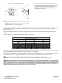
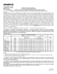
SOUND OUTPUT (SPL) AND CANDELA SETTINGS:
Figure 2:
Showing Location of Candela Selector and Jumper Plugs
CANDELA SELECTOR
TOP
C1
P83511 ( )
AH
15
75
R5
J2
B
R
J2
H
M
L
J3
+ STR -
T B 1
J1
H
M
L
C
O
D
E
3
+ AUD -
J1
30
110
CANDELA
POINTER
C
O
D
E
3
Factory setting is on 15 candela, Medium dB and Code 3.
WARNING: THE CANDELA SELECT SWITCH MUST BE FIELD SET TO THE REQUIRED CANDELA INTENSITY BEFORE INSTALLATION.
WHEN CHANGING THE SETTING OF THE CANDELA SELECT SWITCH, MAKE CERTAIN THAT IT “CLICKS” IN PLACE. AFTER CHANGING THE
CANDELA SETTING, THE APPLIANCE MUST BE RETESTED TO VERIFY PROPER OPERATION.
Figure 3: Jumper Plug Settings for High, Medium, Low dB,
Code 3 Horn (or March Time) and Continuous Horn Setting.
J2
J2
H
M
L
H
M
L
HIGH
HORN
SETTING
•
J2
C
O
D
E
3
H
M
L
MEDIUM
HORN
SETTING
•
LOW
HORN
SETTING
J1
C
O
D
E
3
CODE 3
HORN
SETTING
J1
CONTINUOUS
* HORN
SETTING
•
Use needle nose pliers to pull and properly insert the jumper
plug.
No jumper plug is needed for continuous horn setting.
However, it is recommended that the jumper plug be retained
in the unit for future use (if needed) as shown in Figure 3.
The HS-MC must be set for Code 3 (or March Time) horn
when used with the sync module. If the HS-MC audible is
connected to a coded system, the continuous horn setting
must be used.
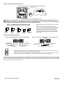
WIRING AND MOUNTING INFORMATION:
Figure 4: Audible signal and strobe operate independently.
TB1
+ STR -
FROM FIRE ALARM
CONTROL PANEL (FACP) OR +
PRECEDING APPLIANCE -
+ AUD - FROM FACP OR
+ PRECEDING APPLIANCE
TO NEXT APPLIANCE +
OR END OF LINE RESISTOR (EOLR).
Figure 4A: Audible and strobe operate in unison. Shunt wires are
supplied.
+ STR FROM FACP OR +
PRECEDING APPLIANCE -
TB1
+ AUD - TO NEXT APPLIANCE
+ OR EOLR
- TO NEXT APPLIANCE
+ OR EOLR.
RED SHUNT WIRE
BLACK SHUNT WIRE
Figure 5:
•
•
HS-MC Appliances have in-out wiring terminals that accepts two #12 to #18 American Wire Gauge (AWG) wires at each
screw terminal. Strip leads 3/8” inches for connection to screw terminals.
Break all in-out wire runs on supervised circuit supervision as shown in Figure 5. The polarity shown in the wiring
diagrams is for the operation of the appliances. The polarity is reversed by the FACP during supervision.
The following figures (A-D) show the maximum number of field wires (conductors) that can enter the backbox used with each mounting option. If these
limits are exceeded, there may be insufficient space in the backbox to accommodate the field wires and stresses from the wires could damage the
product. Check that the installed product will have sufficient clearance and wiring room prior to installing backboxes and conduit, especially if sheathed
multiconductor cable or 3/4" conduit fittings are used.
Siemens Building Technologies, Inc.
P84391-003B
Sheet 3 of 4