1
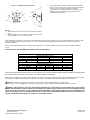
Figure 1: ULC Directional Characteristics
95dB
-6dB
-3dB
-3dB
30°
85dB
27°
-3dB
3.
This model is UL/ULC Listed for indoor use with a temperature
range of +32°F to +120°F (0°C to +49°C) and maximum humidity
of 93% ± 2% RH. The effect of shipping and storage
temperatures shall not adversely affect the performance of the
appliance when it is stored in the original cartons and not
subjected to misuse or abuse.
-6dB
-6dB
60°
20° 30°
48°
83dB
95dB
81dB
80°
-3dB
-6dB
NOTES:
1. The strobe will produce 1 flash per second over the Input Voltage
range.
2. This horn/strobe model meets the required light distribution
patterns defined in UL 1971 and ULC-S526-02.
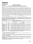
When calculating the total current: Use Tables 3 & 3A to determine the highest value of “RMS Current” for an individual HS-MC then multiply the value
by the total number of HS-MC Appliances. Be sure to add the currents for any other appliances powered by the same source and to include any
required safety factors.
Note: These notification appliances are UL Listed as “Special Application”. They are intended to be used only with Siemens notification appliance
circuits.
CANDELA SETTING WILL DETERMINE THE CURRENT DRAW OF THE PRODUCT.
DC
FWR
DC
FWR
Table 3: Current Ratings (Horn Only)
Maximum RMS Current (Amps)
Input Voltage
Lo
Med
16-33VDC
0.027
0.068
16-33VRMS
0.041
0.050
Table 3A: Current Ratings (Strobe Only)
Maximum RMS Current (Amps)
Input Voltage
15cd
30cd
75cd
16-33VDC
0.064
0.098
0.175
16-33VRMS
0.108
0.164
0.268
Hi
0.110
0.094
110cd
0.233
0.368
THESE APPLIANCES WERE TESTED TO THE VOLTAGE LIMITS OF 16.0-33.0 VOLTS FOR 24V MODELS USING FILTERED DC OR UNFILTERED
FULL-WAVE-RECTIFIED VOLTAGE. DO NOT APPLY VOLTAGE OUTSIDE OF THIS RANGE.
Note: Refer to the installation instructions for the appropriate NAC to find the maximum allowed voltage drop. Use this value along with the current draw
for the appliance to determine the allowable wire resistance. The maximum wire resistance between strobes shall not exceed 35 ohms.
CAUTION: The strobe is not designed to be used on coded systems in which the applied voltage is cycled on and off.
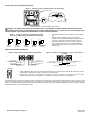
NOTE: The horn circuit is compatible with coded systems only if the unit is wired for independent horn and strobe operation per figure 4.
WARNING: MAKE SURE THAT THE TOTAL RMS CURRENT REQUIRED BY ALL APPLIANCES THAT ARE CONNECTED TO THE SYSTEM’S
PRIMARY AND SECONDARY POWER SOURCES DO NOT EXCEED THE POWER SOURCES’ RATED CAPACITY OR THE CURRENT RATINGS
OF ANY FUSES ON THE CIRCUITS TO WHICH THESE APPLIANCES ARE WIRED. OVERLOADING POWER SOURCES OR EXCEEDING FUSE
RATINGS COULD RESULT IN LOSS OF POWER AND FAILURE TO ALERT OCCUPANTS DURING AN EMERGENCY, WHICH COULD RESULT IN
PROPERTY DAMAGE AND SERIOUS INJURY OR DEATH TO YOU AND/OR OTHERS.
Siemens Building Technologies, Inc.
8 Fernwood Road
Florham Park, New Jersey 07932
P84391-003B
Sheet 2 of 4