1
Using the BayStack 350 Series 10/100 Autosense Switch
Inter-Switch Trunk Configuration
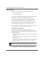
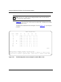
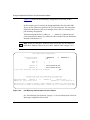
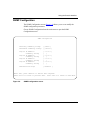
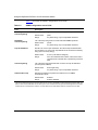
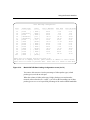
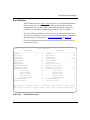
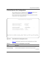
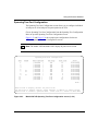
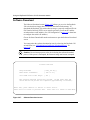
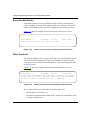
The Inter-Switch Trunk Configuration screen allows you to configure two to eight
switch ports together as members of an inter-switch trunk. Up to four inter-switch
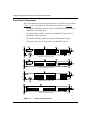
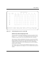
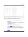
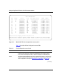
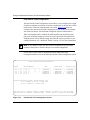
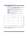
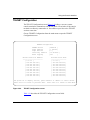
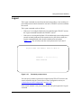
trunks can be created for each BayStack 350 switch. Figure 3-13 shows an
example of the Inter-Switch Trunk Configuration screen. In this screen example,
four trunks are shown, with each trunk configured with two trunk members.
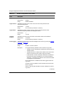
When a configured trunk is enabled, the trunk members (the specified switch
ports) take on default settings necessary for correct operation of the MultiLink
Trunking feature. These default settings can affect the correct operation of your
configured network. See “MultiLink Trunks” on page 1-22 for more information.
Note: If you disable a trunk, you may need to reconfigure the specific trunk
members switch ports to return to the previous switch configuration.
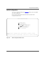
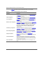
Choose Inter-Switch Trunk Configuration from the MultiLink Trunk
Configuration Menu screen to open the Inter-Switch Trunk Configuration screen.
Inter-Switch Trunk Configuration
Trunk
----I1
I2
I3
I4
Trunk Members
---------------------------[ 25 ][ 26 ][
][
]
[ 13 ][ 14 ][
][
]
[ 19 ][ 20 ]
[ 22 ][ 23 ]
STP
-----------[ Enabled ]
[ Enabled ]
[ Enabled ]
[ Enabled ]
Trunk Mode
--------------[ Enhanced
]
[ Enhanced
]
[ Enhanced
]
[ Enhanced
]
Trunk Status
-----------[ Enabled ]
[ Enabled ]
[ Enabled ]
[ Enabled ]
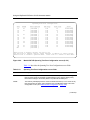
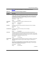
Valid inter-switch trunk configurations are:
1 or 2 trunks of up to 4 links each
Up to 4 trunks of 2 links each
Use space bar to display choices, press <Return> or <Enter> to select choice.
Press Ctrl-R to return to previous menu. Press Ctrl-C to return to Main Menu.
Figure 3-13.
3-28
Inter-Switch Trunk Configuration screen
893-00992-D