1
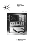
8510XF Network Analyzer Systems
E7340A & E7342A (2 to 85 GHz)
E7350A & E7352A (2 to 110 GHz)
Operating and Service
Manual
Agilent Part Number:
Printed in USA
Print Date: April 2002
Supersedes: June 2001
E7350-90001
Notice
The information contained in this document is subject to change without
notice.
Agilent Technologies makes no warranty of any kind with regard to this
material, including, but not limited to, the implied warranties of
merchantability and fitness for a particular purpose. Agilent Technologies
shall not be liable for errors contained herein or for incidental or
consequential damages in connection with the furnishing, performance, or
use of this material.
Agilent Technologies assumes no responsibility for the use or reliability of
its software on equipment that is not furnished by Agilent Technologies.
This document contains proprietary information which is protected by
copyright. All rights are reserved. No part of this document may be
photocopied, reproduced, or translated to another language without prior
written consent of Agilent Technologies.
Restricted Rights Legend
Use, duplication, or disclosure by the U.S. Government is subject to
restrictions as set forth in subparagraph (c)(1)(ii) of the Rights in Technical
Data and Computer Software clause at DFARS 252.227-7013 for DOD
agencies, and subparagraphs (c)(1) and (c)(2) of the Commercial Computer
Software Restricted Rights clause at FAR 52.227-19 for other agencies.
Hewlett-Packard to Agilent Technologies Transition
This documentation supports a product that previously shipped under the
Hewlett-Packard company brand name. The brand name has now been
changed to Agilent Technologies. The two products are functionally
identical, only our name has changed. This document still includes
references to Hewlett-Packard products, some of which have been
transitioned to Agilent Technologies.
Windows ® is a registered copyright of Microsoft corporation.
© Copyright 1998, 2001, 2002
ii 8510XF Network Analyzer Systems
Agilent Technologies, Inc.
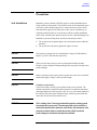
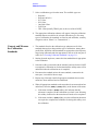
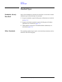
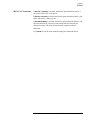
What You’ll Find in This Manual…
Chapter 1
•
Introduction to the 8510XF
Chapter 2
•
How to install the system
Chapter 3
•
How to use the system to make measurements
Chapter 4
•
How to verify the performance of the system
Chapter 5
•
How to maintain the system
Chapter 6
•
How to order replacement parts
Chapter 7
•
How to find information about menus, softkeys, and commands
8510XF Network Analyzer Systems iii
Warranty
Certification
Agilent Technologies certifies that this product met its published
specifications at the time of shipment from the factory. Agilent Technologies
further certifies that its calibration measurements are traceable to the
United States National Institute of Standards and Technology (NIST,
formerly NBS), to the extent allowed by the Institute’s calibration facility,
and to the calibration facilities of other International Standards
Organization members.
DOCUMENTATION
WARRANTY
THE MATERIAL CONTAINED IN THIS DOCUMENT IS
PROVIDED "AS IS," AND IS SUBJECT TO BEING CHANGED,
WITHOUT NOTICE, IN FUTURE EDITIONS. FURTHER, TO
THE MAXIMUM EXTENT PERMITTED BY APPLICABLE LAW,
AGILENT DISCLAIMS ALL WARRANTIES, EITHER EXPRESS
OR IMPLIED WITH REGARD TO THIS MANUAL AND ANY
INFORMATION CONTAINED HEREIN, INCLUDING BUT NOT
LIMITED TO THE IMPLIED WARRANTIES OF
MERCHANTABILITY AND FITNESS FOR A PARTICULAR
PURPOSE. AGILENT SHALL NOT BE LIABLE FOR ERRORS
OR FOR INCIDENTAL OR CONSEQUENTIAL DAMAGES IN
CONNECTION WITH THE FURNISHING, USE, OR
PERFORMANCE OF THIS DOCUMENT OR ANY
INFORMATION CONTAINED HEREIN. SHOULD AGILENT
AND THE USER HAVE A SEPARATE WRITTEN AGREEMENT
WITH WARRANTY TERMS COVERING THE MATERIAL IN
THIS DOCUMENT THAT CONFLICT WITH THESE TERMS,
THE WARRANTY TERMS IN THE SEPARATE AGREEMENT
WILL CONTROL.
Assistance
Product maintenance agreements and other customer assistance agreements
are available for Agilent Technologies products.
For assistance, call your local Agilent Technologies office (see “Contacting
Agilent”)
iv 8510XF Network Analyzer Systems
Contacting Agilent
Online assistance: www.agilent.com/find/assist
United States
(tel) 1 800 452 4844
Latin America
(tel) (305) 269 7500
(fax) (305) 269 7599
Canada
(tel) 1 877 894 4414
(fax) (905) 282-6495
Europe
(tel) (+31) 20 547 2323
(fax) (+31) 20 547 2390
New Zealand
(tel) 0 800 738 378
(fax) (+64) 4 495 8950
Japan
(tel) (+81) 426 56 7832
(fax) (+81) 426 56 7840
Australia
(tel) 1 800 629 485
(fax) (+61) 3 9210 5947
Singapore
(tel) 1 800 375 8100
(fax) (65) 836 0252
Malaysia
(tel) 1 800 828 848
(fax) 1 800 801 664
Philippines
(tel) (632) 8426802
(tel) (PLDT subscriber only):
1 800 16510170
(fax) (632) 8426809
(fax) (PLDT subscriber only):
1 800 16510288
Thailand
(tel) outside Bangkok:
(088) 226 008
(tel) within Bangkok:
(662) 661 3999
(fax) (66) 1 661 3714
Hong Kong
(tel) 800 930 871
(fax) (852) 2506 9233
Taiwan
(tel) 0800-047-866
(fax) (886) 2 25456723
People’s Republic of
China
(tel) (preferred):
800-810-0189
(tel) (alternate):
10800-650-0021
(fax) 10800-650-0121
India
(tel) 1-600-11-2929
(fax) 000-800-650-1101
8510XF Network Analyzer Systems v
Safety and Regulatory Information
Safety and Regulatory Information
Review this product and related documentation to familiarize yourself with
safety markings and instructions before you operate the instrument. This
product has been designed and tested in accordance with international
standards.
WARNING
The WARNING notice denotes a hazard. It calls attention to a procedure,
practice, or the like, that, if not correctly performed or adhered to, could result
in personal injury. Do not proceed beyond a WARNING notice until the
indicated conditions are fully understood and met.
CAUTION
The CAUTION notice denotes a hazard. It calls attention to an operating
procedure, practice, or the like, which, if not correctly performed or adhered
to, could result in damage to the product or loss of important data. Do not
proceed beyond a CAUTION notice until the indicated conditions are fully
understood and met.
vi 8510XF Network Analyzer Systems
Safety and Regulatory Information
Instrument Markings
!
When you see this symbol on your instrument, you should refer to the instrument’s
instruction manual for important information.
This symbol indicates hazardous voltages.
The laser radiation symbol is marked on products that have a laser output.
This symbol indicates that the instrument requires alternating current (ac) input.
The C-Tick mark is a registered trademark of the Australian Spectrum Agency.
The CE mark is a registered trademark of the European Community. If it is
accompanied by a year, it indicates the year the design was proven.
The CSA mark is a registered trademark of the Canadian Standards Association.
1SM1-A
This text indicates that the instrument is an Industrial Scientific and Medical Group 1
Class A product (CISPER 11, Clause 4).
This ISM device complies with Canadian ICES-001.
Cet apppareil ISM est conforme a la norme NMB du Canada.
This symbol indicates that the power line switch is ON.
This symbol indicates that the power line switch is OFF or in STANDBY position.
Safety Requirements
Safety Earth
Ground
This product has been designed and tested in accordance with the IEC
Publication 1010, Safety Requirements for Electronic Measuring Apparatus,
and has been supplied in a safe condition. The instruction documentation
contains information and warnings which must be followed by the user to
ensure safe operation and maintain the product in a safe condition.
This is a Safety Class I product (provided with a protective earthing
terminal). An uninterruptible safety earth ground must be provided from the
main power source to the product input wiring terminals, power cord, or
supplied power cord set. Whenever it is likely that the protection has been
impaired, the product must be made inoperative and secured against any
unintended operation.
8510XF Network Analyzer Systems vii
Safety and Regulatory Information
Before Applying Power
Verify that the product is configured to match the available main power
source as described in the input power configuration instructions in this
manual. If this product is to be powered by autotransformer, make sure the
common terminal is connected to the neutral (grounded) side of the ac power
supply.
WARNING
Danger of explosion if battery is incorrectly replaced. Replace only with the
same or equivalent type recommended. Discard used batteries according to
manufacturers’s instructions.
NOTE
Please refer to the 8510C On-Ssite Service Manual for additional
information (part number 08510-90282).
viii 8510XF Network Analyzer Systems
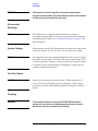
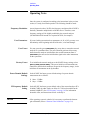
Typeface Conventions
Typeface Conventions
•
Used to emphasize important information:
Use this software only with the xxxxxX system.
•
Used for the title of a publication:
Refer to the xxxxxX System-Level User’s Guide.
•
Used to indicate a variable:
Type LOAD BIN filename.
Instrument Display
•
Used to show on-screen prompts and messages that you will see on the
display of an instrument:
The xxxxxX will display the message CAL1 SAVED.
[Keycap]
•
Used for labeled keys on the front panel of an instrument or on a
computer keyboard:
Press [Return].
{Softkey}
•
Used for simulated keys that appear on an instrument display:
Press {Prior Menu}.
User Entry
•
Used to indicate text that you will enter using the computer keyboard;
text shown in this typeface must be typed exactly as printed:
Type LOAD PARMFILE
•
Used for examples of programming code:
Italics
#endif // ifndef NO_CLASS
Path Name
•
Used for a subdirectory name or file path:
Edit the file usr/local/bin/sample.txt
Computer Display
•
Used to show messages, prompts, and window labels that appear on a
computer monitor:
The Edit Parameters window will appear on the screen.
•
Used for menus, lists, dialog boxes, and button boxes on a computer
monitor from which you make selections using the mouse or keyboard:
Double-click EXIT to quit the program.
8510XF Network Analyzer Systems ix
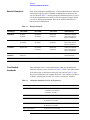
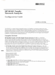
Compliance with Standards
Compliance with Standards
Compliance with German Noise Requirements
This is to declare that this instrument is in conformance with the German
Regulation on Noise Declaration for Machines (Laermangabe nach der
Maschinenlaermrerordnung −3.GSGV Deutschand).
Acoustic Noise Emission/Geraeuschemission
LpA <70 dB
Operator position
Normal position
per ISO 7779
LpA <70 dB
am Arbeitsplatz
normaler Betrieb
nach DIN 45635 t.19
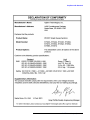
Compliance with EEC Directives
See the declaration of conformity on the following page.
x 8510XF Network Analyzer Systems
Compliance with Standards
8510XF Network Analyzer Systems xi
Compliance with Standards
xii 8510XF Network Analyzer Systems
Contents
Notice . . . . . . . . . . . . . . . . . . . . . . . . . . . . . . . . . . . . . . . . . . . . . . . . . . . . . ii
What You’ll Find in This Manual… . . . . . . . . . . . . . . . . . . . . . . . . . . . . . iii
Warranty . . . . . . . . . . . . . . . . . . . . . . . . . . . . . . . . . . . . . . . . . . . . . . . . . . . iv
Certification . . . . . . . . . . . . . . . . . . . . . . . . . . . . . . . . . . . . . . . . . . . . . iv
DOCUMENTATION WARRENTY . . . . . . . . . . . . . . . . . . . . . . . . . . . iv
Assistance . . . . . . . . . . . . . . . . . . . . . . . . . . . . . . . . . . . . . . . . . . . . . . . iv
Contacting Agilent . . . . . . . . . . . . . . . . . . . . . . . . . . . . . . . . . . . . . . . . . . . v
Safety and Regulatory Information . . . . . . . . . . . . . . . . . . . . . . . . . . . . . . vi
Safety Requirements . . . . . . . . . . . . . . . . . . . . . . . . . . . . . . . . . . . . . . vii
Safety Earth Ground . . . . . . . . . . . . . . . . . . . . . . . . . . . . . . . . . . . . . . vii
Before Applying Power . . . . . . . . . . . . . . . . . . . . . . . . . . . . . . . . . . viii
Typeface Conventions . . . . . . . . . . . . . . . . . . . . . . . . . . . . . . . . . . . . . . . ix
Compliance with Standards . . . . . . . . . . . . . . . . . . . . . . . . . . . . . . . . . . . . x
1.
Introduction
Finding System Information . . . . . . . . . . . . . . . . . . . . . . . . . . . . . . . . . . 1-2
Sources of Information . . . . . . . . . . . . . . . . . . . . . . . . . . . . . . . . . . . 1-2
8510XF Network Analyzer Systems . . . . . . . . . . . . . . . . . . . . . . . . . . . 1-4
System Description . . . . . . . . . . . . . . . . . . . . . . . . . . . . . . . . . . . . . . . . . 1-5
Two Versions of the 8510XF . . . . . . . . . . . . . . . . . . . . . . . . . . . . . . 1-5
What’s Included . . . . . . . . . . . . . . . . . . . . . . . . . . . . . . . . . . . . . . . . 1-5
Frequency Limits . . . . . . . . . . . . . . . . . . . . . . . . . . . . . . . . . . . . . . . 1-5
Partial Systems . . . . . . . . . . . . . . . . . . . . . . . . . . . . . . . . . . . . . . . . . 1-5
Options . . . . . . . . . . . . . . . . . . . . . . . . . . . . . . . . . . . . . . . . . . . . . . . . . . 1-8
Option 005 (45 MHz to 2 GHz) . . . . . . . . . . . . . . . . . . . . . . . . . . . . 1-8
Option 006 (RF Passthrough) . . . . . . . . . . . . . . . . . . . . . . . . . . . . . . 1-8
Option 010 (Time Domain) . . . . . . . . . . . . . . . . . . . . . . . . . . . . . . . 1-9
Option 230 (Line Voltage) . . . . . . . . . . . . . . . . . . . . . . . . . . . . . . . . 1-9
Upgrade Paths . . . . . . . . . . . . . . . . . . . . . . . . . . . . . . . . . . . . . . . . . . . . 1-10
2.
Installation
Site Preparation . . . . . . . . . . . . . . . . . . . . . . . . . . . . . . . . . . . . . . . . . . . . 2-2
Power Requirements . . . . . . . . . . . . . . . . . . . . . . . . . . . . . . . . . . . . . 2-2
Environmental Requirements . . . . . . . . . . . . . . . . . . . . . . . . . . . . . . 2-3
Receiving the System . . . . . . . . . . . . . . . . . . . . . . . . . . . . . . . . . . . . . . . 2-5
The System as Shipped . . . . . . . . . . . . . . . . . . . . . . . . . . . . . . . . . . . 2-5
Agilent Technologies Customer Engineering . . . . . . . . . . . . . . . . . . 2-5
In Case of Problems with the Shipment . . . . . . . . . . . . . . . . . . . . . . 2-5
Precautions . . . . . . . . . . . . . . . . . . . . . . . . . . . . . . . . . . . . . . . . . . . . . . . 2-9
Safe Installation . . . . . . . . . . . . . . . . . . . . . . . . . . . . . . . . . . . . . . . . 2-9
Electrostatic Discharge . . . . . . . . . . . . . . . . . . . . . . . . . . . . . . . . . . 2-10
System Voltages . . . . . . . . . . . . . . . . . . . . . . . . . . . . . . . . . . . . . . . 2-10
8510XF Network Analyzer Systems Operating and Service Manual Contents xiii
Test Port Inputs . . . . . . . . . . . . . . . . . . . . . . . . . . . . . . . . . . . . . . . .
Cleaning . . . . . . . . . . . . . . . . . . . . . . . . . . . . . . . . . . . . . . . . . . . . .
Unpacking the System . . . . . . . . . . . . . . . . . . . . . . . . . . . . . . . . . . . . . .
Tools Required . . . . . . . . . . . . . . . . . . . . . . . . . . . . . . . . . . . . . . . .
Basic System Configurations . . . . . . . . . . . . . . . . . . . . . . . . . . . . . . . . .
Installing the Work Surface . . . . . . . . . . . . . . . . . . . . . . . . . . . . . . .
Millimeter-Wave Controller . . . . . . . . . . . . . . . . . . . . . . . . . . . . . . . . .
LEDs . . . . . . . . . . . . . . . . . . . . . . . . . . . . . . . . . . . . . . . . . . . . . . . .
Connectors (Port 1) . . . . . . . . . . . . . . . . . . . . . . . . . . . . . . . . . . . . .
Connectors (Port 2) . . . . . . . . . . . . . . . . . . . . . . . . . . . . . . . . . . . . .
GPIB Address Switch . . . . . . . . . . . . . . . . . . . . . . . . . . . . . . . . . . .
Fuse . . . . . . . . . . . . . . . . . . . . . . . . . . . . . . . . . . . . . . . . . . . . . . . . .
Test Heads . . . . . . . . . . . . . . . . . . . . . . . . . . . . . . . . . . . . . . . . . . . . . . .
Connector Positions . . . . . . . . . . . . . . . . . . . . . . . . . . . . . . . . . . . .
Power Supply Inputs . . . . . . . . . . . . . . . . . . . . . . . . . . . . . . . . . . . .
Illustrations . . . . . . . . . . . . . . . . . . . . . . . . . . . . . . . . . . . . . . . . . . .
Test Ports . . . . . . . . . . . . . . . . . . . . . . . . . . . . . . . . . . . . . . . . . . . . .
Controller / Test Head Interconnections . . . . . . . . . . . . . . . . . . . . . . . .
Systems With Option 005 . . . . . . . . . . . . . . . . . . . . . . . . . . . . . . . .
Instruments Without Option 005 . . . . . . . . . . . . . . . . . . . . . . . . . . .
Cable List . . . . . . . . . . . . . . . . . . . . . . . . . . . . . . . . . . . . . . . . . . . . . . . .
Duplicate Listings . . . . . . . . . . . . . . . . . . . . . . . . . . . . . . . . . . . . . .
Turning On the System . . . . . . . . . . . . . . . . . . . . . . . . . . . . . . . . . . . . .
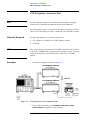
System Operational Test . . . . . . . . . . . . . . . . . . . . . . . . . . . . . . . . . . . .
Test Procedure . . . . . . . . . . . . . . . . . . . . . . . . . . . . . . . . . . . . . . . . .
Operating Notes . . . . . . . . . . . . . . . . . . . . . . . . . . . . . . . . . . . . . . . . . . .
3.
2-10
2-10
2-11
2-11
2-17
2-20
2-23
2-23
2-24
2-24
2-25
2-25
2-26
2-26
2-26
2-26
2-27
2-28
2-28
2-30
2-32
2-32
2-38
2-39
2-40
2-42
Operation
8510XF Operating System . . . . . . . . . . . . . . . . . . . . . . . . . . . . . . . . . . . 3-2
Checking the Operating System . . . . . . . . . . . . . . . . . . . . . . . . . . . . 3-2
Measurement Calibration . . . . . . . . . . . . . . . . . . . . . . . . . . . . . . . . . . . . . 3-6
Why Calibration Is Essential . . . . . . . . . . . . . . . . . . . . . . . . . . . . . . . 3-6
When to Repeat the Calibration . . . . . . . . . . . . . . . . . . . . . . . . . . . . 3-6
Calibration Techniques . . . . . . . . . . . . . . . . . . . . . . . . . . . . . . . . . . . 3-7
Types of Calibration Kits . . . . . . . . . . . . . . . . . . . . . . . . . . . . . . . . . 3-7
Calibration Procedure . . . . . . . . . . . . . . . . . . . . . . . . . . . . . . . . . . . . . . . 3-9
Load Calibration Constants . . . . . . . . . . . . . . . . . . . . . . . . . . . . . . . . 3-9
Set Up the Analyzer . . . . . . . . . . . . . . . . . . . . . . . . . . . . . . . . . . . . . 3-9
Connect and Measure the Calibration Standards . . . . . . . . . . . . . . 3-10
Choosing Calibration Standards . . . . . . . . . . . . . . . . . . . . . . . . . . . . . . 3-11
Connector Sex . . . . . . . . . . . . . . . . . . . . . . . . . . . . . . . . . . . . . . . . . 3-11
Offset Shorts . . . . . . . . . . . . . . . . . . . . . . . . . . . . . . . . . . . . . . . . . . 3-11
Banded Standards . . . . . . . . . . . . . . . . . . . . . . . . . . . . . . . . . . . . . . 3-12
Non-Banded Standards . . . . . . . . . . . . . . . . . . . . . . . . . . . . . . . . . . 3-12
Calibration Types . . . . . . . . . . . . . . . . . . . . . . . . . . . . . . . . . . . . . . . . . . 3-13
S22 1-Port . . . . . . . . . . . . . . . . . . . . . . . . . . . . . . . . . . . . . . . . . . . . 3-16
Standard Types . . . . . . . . . . . . . . . . . . . . . . . . . . . . . . . . . . . . . . . . . . . 3-20
Contents xiv 8510XF Network Analyzer Systems Operating and Service Manual
Standards Already Described . . . . . . . . . . . . . . . . . . . . . . . . . . . . .
Other Standards . . . . . . . . . . . . . . . . . . . . . . . . . . . . . . . . . . . . . . .
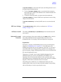
Port Power . . . . . . . . . . . . . . . . . . . . . . . . . . . . . . . . . . . . . . . . . . . . . . .
RF Power . . . . . . . . . . . . . . . . . . . . . . . . . . . . . . . . . . . . . . . . . . . . . . .
RF Power Configuration . . . . . . . . . . . . . . . . . . . . . . . . . . . . . . . . .
LO Power . . . . . . . . . . . . . . . . . . . . . . . . . . . . . . . . . . . . . . . . . . . . . . .
LO Power Configuration . . . . . . . . . . . . . . . . . . . . . . . . . . . . . . . .
LO Power Settings . . . . . . . . . . . . . . . . . . . . . . . . . . . . . . . . . . . . .
Service . . . . . . . . . . . . . . . . . . . . . . . . . . . . . . . . . . . . . . . . . . . . . . . . . .
85102 Service . . . . . . . . . . . . . . . . . . . . . . . . . . . . . . . . . . . . . . . . .
Leveling Settings . . . . . . . . . . . . . . . . . . . . . . . . . . . . . . . . . . . . . .
IF Frequency . . . . . . . . . . . . . . . . . . . . . . . . . . . . . . . . . . . . . . . . . . . . .
Alternative 1.0 mm Calibrations . . . . . . . . . . . . . . . . . . . . . . . . . . . . . .
Broadband Standards . . . . . . . . . . . . . . . . . . . . . . . . . . . . . . . . . . .
Operation Using a Wafer Probe Station . . . . . . . . . . . . . . . . . . . . . . . .
System Configuration . . . . . . . . . . . . . . . . . . . . . . . . . . . . . . . . . . .
Available Equipment . . . . . . . . . . . . . . . . . . . . . . . . . . . . . . . . . . .
Device Connections . . . . . . . . . . . . . . . . . . . . . . . . . . . . . . . . . . . .
Types of Probe Stations . . . . . . . . . . . . . . . . . . . . . . . . . . . . . . . . .
4.
3-20
3-20
3-28
3-30
3-30
3-36
3-36
3-37
3-38
3-38
3-41
3-42
3-43
3-43
3-46
3-46
3-47
3-47
3-47
Performance Verification
When to Verify . . . . . . . . . . . . . . . . . . . . . . . . . . . . . . . . . . . . . . . . . 4-2
Materials Required . . . . . . . . . . . . . . . . . . . . . . . . . . . . . . . . . . . . . 4-3
Calibration and Frequency Ranges . . . . . . . . . . . . . . . . . . . . . . . . . . 4-3
Verification Setup . . . . . . . . . . . . . . . . . . . . . . . . . . . . . . . . . . . . . . . . . 4-5
General Preparation . . . . . . . . . . . . . . . . . . . . . . . . . . . . . . . . . . . . . 4-5
Software Installation . . . . . . . . . . . . . . . . . . . . . . . . . . . . . . . . . . . . . 4-5
Software Configuration . . . . . . . . . . . . . . . . . . . . . . . . . . . . . . . . . . 4-6
Verification Procedures . . . . . . . . . . . . . . . . . . . . . . . . . . . . . . . . . . . . . 4-9
Low Band Verification (< 50 GHz) . . . . . . . . . . . . . . . . . . . . . . . . . 4-9
CW Frequency Accuracy Test . . . . . . . . . . . . . . . . . . . . . . . . . . . . . . . 4-14
Materials Required . . . . . . . . . . . . . . . . . . . . . . . . . . . . . . . . . . . . . 4-14
Procedure . . . . . . . . . . . . . . . . . . . . . . . . . . . . . . . . . . . . . . . . . . . . 4-14
Performance Test Record . . . . . . . . . . . . . . . . . . . . . . . . . . . . . . . . 4-16
5.
System Maintenance
Electrostatic Discharge . . . . . . . . . . . . . . . . . . . . . . . . . . . . . . . . . . . . . .
1.0 mm Connector Care . . . . . . . . . . . . . . . . . . . . . . . . . . . . . . . . . . . . .
Detector Gain Calibration . . . . . . . . . . . . . . . . . . . . . . . . . . . . . . . . . . . .
Purpose of the Calibration . . . . . . . . . . . . . . . . . . . . . . . . . . . . . . . .
The Calibration Process . . . . . . . . . . . . . . . . . . . . . . . . . . . . . . . . . .
When to Calibrate . . . . . . . . . . . . . . . . . . . . . . . . . . . . . . . . . . . . . . .
Procedure . . . . . . . . . . . . . . . . . . . . . . . . . . . . . . . . . . . . . . . . . . . . .
Conversion Loss Calibration . . . . . . . . . . . . . . . . . . . . . . . . . . . . . . . . . .
Purpose of the Calibration . . . . . . . . . . . . . . . . . . . . . . . . . . . . . . . .
The Calibration Process . . . . . . . . . . . . . . . . . . . . . . . . . . . . . . . . . .
When to Calibrate . . . . . . . . . . . . . . . . . . . . . . . . . . . . . . . . . . . . . . .
Agilent Technologies Customer Engineering . . . . . . . . . . . . . . . . . .
5-2
5-3
5-6
5-6
5-6
5-6
5-7
5-8
5-8
5-8
5-8
5-8
8510XF Network Analyzer Systems Operating and Service Manual Contents xv
Theory of Operation . . . . . . . . . . . . . . . . . . . . . . . . . . . . . . . . . . . . . . . . 5-9
Signal Separation . . . . . . . . . . . . . . . . . . . . . . . . . . . . . . . . . . . . . . . 5-9
Frequency Control . . . . . . . . . . . . . . . . . . . . . . . . . . . . . . . . . . . . . . 5-10
The Leveling Loop . . . . . . . . . . . . . . . . . . . . . . . . . . . . . . . . . . . . . 5-15
Level Calibration . . . . . . . . . . . . . . . . . . . . . . . . . . . . . . . . . . . . . . . 5-18
LO Levels . . . . . . . . . . . . . . . . . . . . . . . . . . . . . . . . . . . . . . . . . . . . 5-19
System Block Diagrams . . . . . . . . . . . . . . . . . . . . . . . . . . . . . . . . . . . . 5-21
110 GHz Systems . . . . . . . . . . . . . . . . . . . . . . . . . . . . . . . . . . . . . . 5-21
Troubleshooting . . . . . . . . . . . . . . . . . . . . . . . . . . . . . . . . . . . . . . . . . . . 5-37
Cycle Power . . . . . . . . . . . . . . . . . . . . . . . . . . . . . . . . . . . . . . . . . . 5-37
Hardware Configuration Check . . . . . . . . . . . . . . . . . . . . . . . . . . . . 5-37
Firmware Configuration Check . . . . . . . . . . . . . . . . . . . . . . . . . . . . 5-38
6.
Replaceable Parts
Parts Listed . . . . . . . . . . . . . . . . . . . . . . . . . . . . . . . . . . . . . . . . . . . . 6-2
How to Order . . . . . . . . . . . . . . . . . . . . . . . . . . . . . . . . . . . . . . . . . . . 6-2
Frequency Ranges . . . . . . . . . . . . . . . . . . . . . . . . . . . . . . . . . . . . . . . 6-2
Categorization of Components . . . . . . . . . . . . . . . . . . . . . . . . . . . . . 6-3
110 GHz Systems . . . . . . . . . . . . . . . . . . . . . . . . . . . . . . . . . . . . . . . . . . 6-4
Complete System . . . . . . . . . . . . . . . . . . . . . . . . . . . . . . . . . . . . . . . 6-4
85 GHz Systems . . . . . . . . . . . . . . . . . . . . . . . . . . . . . . . . . . . . . . . . . . . 6-7
Complete System . . . . . . . . . . . . . . . . . . . . . . . . . . . . . . . . . . . . . . . 6-7
Millimeter-Wave Controller . . . . . . . . . . . . . . . . . . . . . . . . . . . . . . . . . 6-10
7.
Menus & Commands
Menu Maps . . . . . . . . . . . . . . . . . . . . . . . . . . . . . . . . . . . . . . . . . . . . . . . 7-2
New GPIB Commands . . . . . . . . . . . . . . . . . . . . . . . . . . . . . . . . . . . . . 7-43
Unsupported GPIB Commands . . . . . . . . . . . . . . . . . . . . . . . . . . . . . . . 7-47
New Messages . . . . . . . . . . . . . . . . . . . . . . . . . . . . . . . . . . . . . . . . . . . . 7-49
Contents xvi 8510XF Network Analyzer Systems Operating and Service Manual
1
Introduction
In This Chapter...
•
•
•
•
•
Finding System Information, page 1-2
8510XF Network Analyzer Systems, page 1-4
System Description, page 1-5
Options, page 1-8
Upgrade Paths, page 1-10
8510XF Network Analyzer Systems 1-1
Introduction
Finding System Information
Finding System Information
Sources of Information
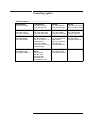
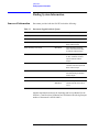
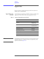
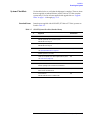
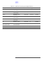
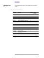
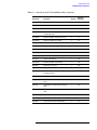
Table 1-1
Documents provided with the 8510XF include the following:
Documents Supplied with the System
Document
Part Number
Description
8510XF Operation and Service Manual
E7350-90001
8510XF system manual
8510C Network Analyzer Manuals set 08510-90275 includes:
8510C Operating and Programming Manual
08510-90281
A detailed operator’s guide to the
8510C network analyzer
8510C Introductory User’s Guide
08510-90290
A brief introduction to functions,
menus, and measurement setups
for the 8510C network analyzer
8510C Quick Reference Guide
08510-90292
An abbreviated, pocket-sized guide
to codes, commands, and menu
maps for the 8510C network
analyzer
8510C Keyword Dictionary
08510-90280
A thorough presentation of codes,
commands, and menu maps for the
8510C network analyzer
8510C On-Site Service Manual
08510-90282
A detailed guide to maintenance
and troubleshooting for the 8510C
network analyzer
8360 Series Dedicated Source Manual set 08360-90138 includes:
83651B & 83621B Manuals
08360-90136
08360-90137
Troubleshooting and service
manuals for the RF source and LO
source
Another important document is the Operating and Service Manual for the
85059A 1.0 mm Precision Calibration and Verification Kit (the Agilent part
number of the manual is 85059-90003).
1-2 8510XF Network Analyzer Systems
Introduction
Finding System Information
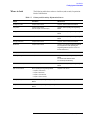
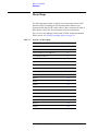
Where to look
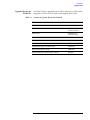
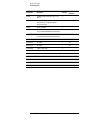
The following table shows where to look first (and second) for particular
kinds of information.
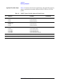
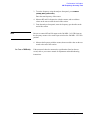
Table 1-2
Primary and Secondary Information Sources
Subject
First Source
Other Sources
Installing the system
Chapter 2 of this manual
Chapter 9, 8510C On-Site Service Manual
Using menus
Chapter 3 of this manual
(also see Chapter 7 for menu maps)
Chapter 4, 8510C Operating and Programming
Manual
Using system functions
Chapter 3 of this manual
Chapter 5, 8510C Operating and Programming
Manual
Measurement calibration
Chapter 3 of this manual
Chapter 8, 8510C Operating and Programming
Manual
Verifying performance
Chapter 4 of this manual
Chapter 8, 8510C On-Site Service Manual
Maintenance
Chapter 5 of this manual
Chapters 7 & 10, 8510C On-Site Service Manual
Also: Supplement to 8510C Operating and
Programming Manual (“Operator’s Check and
Routine Maintenance”)
Ordering replacement parts
Chapter 6 of this manual
Chapter 5, 8510C On-Site Service Manual
GPIB programming
Chapter 7 of this manual
Chapter 13, 8510C Operating and Programming
Manual
Also: 8510C Quick Reference Guide
Also: 8510C Keyword Dictionary
Basics of network analysis
8510C Introductory User’s Guide
Chapter 3, 8510C Operating and Programming
Manual
Types of measurement
8510C Operating and Programming Manual:
Chapter 3 of this manual
• Chapter 9 (Transmission)
• Chapter 10 (Reflection)
• Chapter 11 (Time Domain)
• Chapter 12 (Power Domain)
Printing & plotting
Chapter 6, 8510C Operating and Programming
Manual
Using the disk drive
Chapter 7, 8510C Operating and Programming
Manual
8510XF Network Analyzer Systems 1-3
Introduction
8510XF Network Analyzer Systems
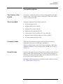
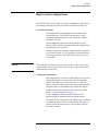
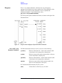
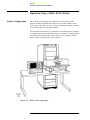
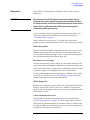
8510XF Network Analyzer Systems
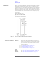
The 8510XF is a vector network analyzer with an extremely wide frequency
range. It is available in two basic versions, with frequency ranges of
2 to 85 GHz and 2 to 110 GHz. Both ranges can be optionally extended
downward to 45 MHz.
The 8510XF uses the same test port connections throughout its entire range
of test frequencies. It is never necessary to make and break connections in
order to complete a test.
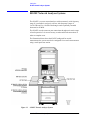
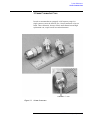
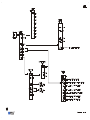
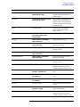
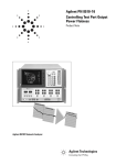
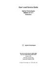
The illustration below shows the 8510XF configured for coaxial
measurement; the system can also be configured for on-wafer measurement
using a wafer probe test station.
Figure 1-1
8510XF Network Analyzer System
1-4 8510XF Network Analyzer Systems
Introduction
System Description
System Description
Two Versions of the
8510XF
The system is available in two basic versions, distinguished by their upper
frequency limits. The 85 GHz version is ordered as E7340A; the 110 GHz
version is ordered as E7350A.
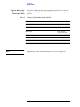
What’s Included
The major components of the 8510XF system are:
•
•
•
•
•
•
•
Frequency Limits
Network analyzer, 8510C
Synthesized RF source, 83651B
Synthesized LO source, 83621B
Millimeter-wave controller, E7341A
Left test head, E7342L (85 GHz) or E7352L (110 GHz)
Right test head, E7342R (85 GHz) or E7352R (110 GHz)
1.6 meter instrument rack (E3661A)
As the list above indicates, the upper frequency limit of the system is
determined by the type of test head that is included in it.
The lower frequency limit of an 8510XF system is normally 2 GHz. With
Option 005 installed, the lower frequency limit is 45 MHz. (See “Options”
on page 1-8.)
Partial Systems
Customers who already have the network analyzer and the sources can order
partial systems which omit those items. The partial systems are known as
millimeter-wave subsystems; the 85 GHz version is ordered as E7342A, and
the 110 GHz version is ordered as E7352A.
In addition, 8510XF upgrade kits are available for other Agilent test systems
(see “Upgrade Paths” on page 1-10).
8510XF Network Analyzer Systems 1-5
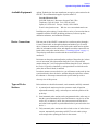
Introduction
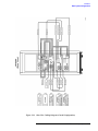
System Description
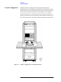
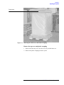
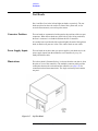
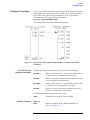
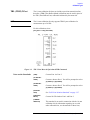
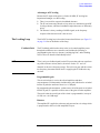
Coaxial Configuration
When the 8510XF is configured for measurement through coaxial
connections, the network analyzer, the millimeter-wave controller, and the
RF and LO sources are all installed in the rack. The test heads are placed on
a work surface which is mounted below the millimeter-wave controller.
The test ports feature 1.0 mm coaxial connectors. The device under test is
typically connected to one test port directly, and to the other test port by way
of a coaxial cable (or it is connected to the ports through two coaxial cables).
Figure 1-2
8510XF, Configured for Coaxial Measurement
1-6 8510XF Network Analyzer Systems
Introduction
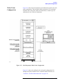
System Description
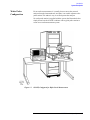
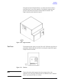
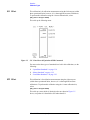
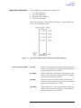
Wafer Probe
Configuration
For on-wafer measurements, it is usually best to remove the network
analyzer from the instrument rack, and place it on a table adjacent to the
probe station. This makes it easy to see and operate the analyzer.
No wafer probe station is supplied with the system; the illustration below
simply shows how the 8510XF combines with a typical probe station to
create an on-wafer measurement system.
Figure 1-3
8510XF, Configured for Wafer-Probe Measurement
8510XF Network Analyzer Systems 1-7
Introduction
Options
Options
Option 005
(45 MHz to 2 GHz)
This option extends the lower limit of the 8510XF frequency range
downward to 45 MHz. The option is implemented by adding four
low-frequency mixers, which are dedicated to the .045 to 2 GHz frequency
range. These mixers are installed in the millimeter-wave controller.
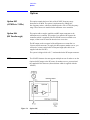
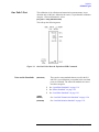
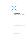
Option 006
(RF Passthrough)
This option adds a coupler, amplifier, and RF output connector to the
millimeter-wave controller. The purpose is to make the RF input to the
controller (which is supplied by the 83651B RF source) available as an
output, so that it can be routed to other devices or test sets.
The RF output on the rear panel of the millimeter-wave controller is a
2.4 mm coaxial connector. To supply this RF output to another test set, you
will need a 2.4 mm coaxial cable of adequate length (this cable is not
supplied with the 8510XF).
The system is shipped with a 50 Ω load attached to the RF output connector.
NOTE
The 8510XF firmware does not support multiple test sets. In order to use the
Option 006 RF output as the RF source for another test set, you must load
the standard 8510C firmware (from a diskette which is supplied with the
8510XF).
Figure 1-4
Option 006
1-8 8510XF Network Analyzer Systems
Introduction
Options
Option 010
(Time Domain)
This option makes it possible to use the 8510XF in time domain mode. The
option is implemented through modification of the network analyzer
operating system.
NOTE
Option 010 is available only for complete systems (E7340A and E7350A).
Option 230
(Line Voltage)
This option configures the 8510XF for 220/240 line voltage operation.
8510XF Network Analyzer Systems 1-9
Introduction
Upgrade Paths
Upgrade Paths
Kits are available for upgrading another type of 8510C test system to an
8510XF system, as described below.
Upgrade Kits for the
85107A/B
Table 1-3
NOTE
An 85107A/B can be upgraded to an 8510XF, in either the 110 GHz version
(upgrade kit E7355A) or the 85 GHz version (upgrade kit E7345A).
Contents of Upgrade Kits for the 85107A/B
Item
Part#
Millimeter-wave controller
E7341A
Left test head
E7342L (85 GHz)
or E7352L (110 GHz)
Right test head
E7342R (85 GHz)
or E7352R (110 GHz)
LO source
83621B
Rack flange kit for LO source
83621B #913
8510XF operating & service manual
E7350-90001
E7345A/E7355A upgrade kit installation manual
E7350-90003
8510XF system software on diskette
E7340-10001
8 chips for expanding non-volatile memory in the 8510C
1818-4075
The upgrade kits for the 85107A/B can also be used for an 85109C system
which lacks Option 002. To upgrade an 85109C with Option 002, see the
upgrade kit described on page 1-12).
1-10 8510XF Network Analyzer Systems
Introduction
Upgrade Paths
Upgrade Kits for the
85106C/D
Table 1-4
An 85106C/D can be upgraded to an 8510XF, in either the 110 GHz version
(upgrade kit E7356A) or the 85 GHz version (upgrade kit E7346A).
Contents of Upgrade Kits for the 85106C/D
Item
Part#
Millimeter-wave controller
E7341A
Left test head
E7342L (85 GHz)
or E7352L (110 GHz)
Right test head
E7342R (85 GHz)
or E7352R (110 GHz)
RF source
83651B
Rack flange kit for RF source
83651B #913
8510XF operating & service manual
E7350-90001
E7346A/E7356A upgrade kit installation manual
E7350-90004
8510XF system software on diskette
E7340-10001
8 chips for expanding non-volatile memory in the 8510C
1818-4075
8510XF Network Analyzer Systems 1-11
Introduction
Upgrade Paths
Upgrade Kits for the
85109C
(With Option 002)
Table 1-5
NOTE
An 85109C with Option 002 can be upgraded to an 8510XF, in either the
110 GHz version (upgrade kit E7357A) or the 85 GHz version (upgrade kit
E7347A).
Contents of Upgrade Kits for the 85109C
Item
Part#
Millimeter-wave controller
E7341A
Left test head
E7342L (85 GHz)
or E7352L (110 GHz)
Right test head
E7342R (85 GHz)
or E7352R (110 GHz)
8510XF operating & service manual
E7350-90001
E7347A/E7357A upgrade kit installation manual
E7350-90005
8510XF system software on diskette
E7340-10001
8 chips for expanding non-volatile memory in the 8510C
1818-4075
To upgrade an 85109C which lacks Option 002, see the upgrade kit
described on page 1-10.
1-12 8510XF Network Analyzer Systems
2
Installation
In This Chapter...
Site Preparation, page 2-2
Power Requirements, page 2-2
Environmental Requirements, page 2-3
Receiving the System, page 2-5
Precautions, page 2-9
Unpacking the System, page 2-11
Basic System Configurations, page 2-17
Millimeter-Wave Controller, page 2-23
Test Heads, page 2-26
Controller / Test Head Interconnections, page 2-28
Cable List, page 2-32
Other Connections and Settings, page 2-37
Turning On the System, page 2-38
System Operational Test, page 2-39
Operating Notes, page 2-42
8510XF Network Analyzer Systems 2-1
Installation
Site Preparation
Site Preparation
Power Requirements
Table 2-1
Before installing the system, be sure that the required ac power is available
at all necessary locations.
•
Three-wire power cables (which provide a safety ground) must be used
with all instruments.
•
Air-conditioning equipment (or other motor-operated equipment) should
not be placed on the same ac line that powers the system.
•
The table below lists the maximum VA ratings and BTU/hour ratings for
all instruments in the system. This table can be used to determine both
the electrical requirements and the air conditioning requirements of the
system.
Power requirements of the system
Standard Equipment
Instrument
Maximum VA Rating
Maximum BTU/hour
85101C display processor
250
850
85102B IF detector
210
714
83621B synthesized source (LO)
400
1360
83651B synthesized source (RF)
400
1360
E7341A millimeter-wave controller
500
1700
E7342L left test head (85 GHz)
or E7352L left test head (110 GHz)
(powered from controller)
(powered from controller)
E7342R right test head (85 GHz)
or E7352R right test head (110 GHz)
(powered from controller)
(powered from controller)
Total
1760
5984
NOTES:
(1) Values are based on 120 Vac supplied to each instrument at 60 Hz.
(2) The millimeter-wave controller supplies power to the test heads.
2-2 8510XF Network Analyzer Systems
Installation
Site Preparation
Environmental
Requirements
The environmental requirements of the system are listed in the table below.
Note that these requirements are the same as those of the 8510C Network
Analyzer.
Table 2-2
Environmental Requirements
Temperature (Operation)
5 °C to 40 °C (41 °F to 104 °F)
Temperature (Storage)
−40 °C to +65 °C (-40 °F to +158 °F)
Temperature (Measurement Calibration)
20 °C to 26 °C (68 °F to 79 °F)
Temperature (Performance Verification)
Temperature must be within 1 °C (1.8 °F) of the
temperature at which the measurement
calibration was performed.
Relative Humidity (Operation)
5% to 95% at 40 °C or less (non-condensing)
Relative Humidity (Storage)
5% to 95% at 65 °C or less (non-condensing)
Pressure Altitude (Operation or Storage)
Less than 4600 meters (~15,000 feet)
System heating and cooling
Install air conditioning and heating, if necessary to maintain the ambient
temperature within the appropriate range (as given in the table above). Air
conditioning capacity must be consistent with the BTU ratings given in the
table under “Power Requirements” on page 2-2.
Required conditions for accuracy-enhanced measurement
Accuracy-enhanced (error-corrected) measurements require the ambient
temperature of the 8510XF to be maintained within ±1°C of the ambient
temperature at calibration.
8510XF Network Analyzer Systems 2-3
Installation
Site Preparation
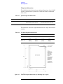
Weight and dimensions
The table below shows the maximum weight and dimensions of the 8510XF
system, as installed in the system rack, with the test heads on an attached
work surface.
Table 2-3
System Weight and Dimensions
Weight
Height
Width
Depth
280.3 kg (618 lbs)
162 cm (63.8 in)
Rack only: 60 cm (23.6 in)
Plus work surface: 100 cm (39.4 in)
Rack Only: 90.5 cm (35.6 in)
Plus work surface: 145.4 cm (57.3 in)
The table below shows the weight and dimensions of a single test head (left
or right):
Table 2-4
Figure 2-1
Test Head Weight and Dimensions
Test Head Model
Weight
Height
Width
Depth
E7342 L/R
9.07 kg
(20 lb)
18.5 cm
(7.3 in)
24.7 cm
(9.7 in)
31.4 cm
(12.4 in)
E7352 L/R
9.75 kg
(21.5 lb)
18.5 cm
(7.3 in)
24.7 cm
(9.7 in)
31.4 cm
(12.4 in)
Testhead Footprint Dimensions for Mounting (left or right)
2-4 8510XF Network Analyzer Systems
Installation
Receiving the System
Receiving the System
The System as Shipped
The 8510XF system will arrive with all rack components and instruments
installed and cabled in the system cabinet. The system cabinet is shipped
upright in a special crate (as illustrated in “Unpacking the System” on
page 2-11). The work surface is included in the system cabinet packaging.
The test heads are packaged separately from the system cabinet, in two
padded cartons.
When the entire shipment has arrived, contact your nearest Agilent
Technologies office to arrange for system installation, if installation is
available in your area (see “Contacting Agilent”).
Agilent Technologies
Customer Engineering
An Agilent Technologies Customer Engineer will be assigned to help you
install the system. During installation, the Customer Engineer will do the
following:
•
•
•
•
•
•
•
In Case of Problems
with the Shipment
Uncrate the system cabinet (see “Unpacking the System” on page 2-11).
Complete the system checklist (see “System Checklists” on page 2-7).
Assemble the work surface and connect it to the system cabinet.
Install the test heads.
Verify that the GPIB addresses are set properly and power up the
system.
Run a performance verification of the system, which includes a
measurement calibration.
Provide user training for one engineer.
If the shipment is damaged or incomplete, notify the nearest Agilent
Technologies office. If the shipping container is damaged or the packaging
material shows signs of stress, notify the carrier as well as the Agilent
Technologies Customer Engineer. Keep the shipping materials for the
carrier’s inspection. Agilent Technologies will arrange for repair or
replacement of damaged equipment without waiting for a claim settlement
from the carrier.
8510XF Network Analyzer Systems 2-5
Installation
Receiving the System
Shipping Containers
Keep the shipping containers in one area until the system checklist has been
completed. This makes it easier to verify that everything ordered has been
shipped.
Keep the containers, and all packing materials, until the entire shipment has
been verified for completeness, and the system has been checked
mechanically and electrically. The crate may be used one more time only to
ship the 8510XF cabinet.
If you need to ship your 8510XF system, repackage it in its original shipping
crate. Make all surface shipments via padded van with an air suspension
ride.
CAUTION
Regardless of the crate style, all surface shipments must be made via padded
van (air suspension ride). Surface shipments in vehicles without air
suspension may result in damage to the system components, cabinet, and
shipping crate.
2-6 8510XF Network Analyzer Systems
Installation
Receiving the System
System Checklists
Standard Items
Table 2-5
Use the tables below to verify that the shipment is complete. These are items
that are supplied (as indicated below) with E7340A or E7350A complete
systems only. For a list of items supplied with upgrade kits see “Upgrade
Paths” on page 1-10 through page 1-12.
Items that are supplied with all 8510XF (E7340A or E7350A) systems are
listed in Table 2-5.
8510XF System Checklist (Standard Items)
✔
Equipment
Serial Number
8510C network analyzer
83621B synthesized source (LO source), with
83621B #913 rack flange kit
83651B synthesized source (RF source), with
83651B #913 rack flange kit
Millimeter-wave controller & test heads -see “Optional/Variable Items” on page 2-8
See page 2-8
E3661A system rack (1.6 meter)
Cables (for a complete list of cables supplied with the system,
see “Cable List” on page 2-32).
N/A
E7340-10001 (8510XF firmware diskette)
N/A
System manual:
8510XF Operating and Service Manual, E7350-90001
N/A
Network analyzer manuals:
8510C Manual set 08510-90275
N/A
Source manuals:
83651B & 83621B Manual set 08360-90138
N/A
8510XF Network Analyzer Systems 2-7
Installation
Receiving the System
Optional/Variable Items
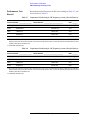
Table 2-6
✔
Table 2-6 lists those items that are supplied only if the applicable frequency
range or option has been ordered with the 8510XF (E7340A or E7350A)
system.
8510XF System Checklist (Optional/Variable Items)
Equipment
Included In
Left test head:
E7342L
E7352L
Systems to 85 GHz
Systems to 110 GHz
Right test head:
E7342R
E7352R
Systems to 85 GHz
Systems to 110 GHz
Millimeter-wave controller:
E7341A
E7341A #005
E7341A #006
E7341A #056
Systems without options
Systems with Option 005
Systems with Option 006
Systems with Options 005 & 006
8510C #010 (time domain option for network analyzer)
Systems with Option 010
85106-60038 (1 meter table top)
E7340A and E7350A complete systems
2-8 8510XF Network Analyzer Systems
Serial Number
N/A
Installation
Precautions
Precautions
Safe Installation
Install the system so that the ON/OFF switch is readily identifiable and is
easily reached by the operator. The ON/OFF switch or the detachable power
cord is the system disconnecting device. It disconnects the mains circuits
from the mains supply before other parts of the system. Alternatively, an
externally installed switch or circuit breaker (which is readily identifiable
and is easily reached by the operator) may be used as a disconnecting device.
Install the system according to the enclosure protection provided:
•
•
The system protects against finger access to hazardous parts within the
enclosure.
The system does not protect against the ingress of water.
CAUTION
This product is designed for use in Installation Category II and Pollution
Degree 2 per IEC 1010 and 664 respectively.
CAUTION
Always use the three-prong ac power cord supplied with this product.
Failure to insure adequate earth grounding by not using this cord may cause
product damage.
CAUTION
Before switching on the system, make sure that the correct fuse is installed,
and that the supply voltage is in the specified range.
CAUTION
Ventilation requirements:
Convection in and out of the system cabinet must not be restricted. The
ambient temperature (outside the cabinet) must be less than the maximum
operating temperature of the system by 4°C for every 100 watts dissipated in
the cabinet. If the total power dissipated in the cabinet is greater than 800
watts, then forced convection must be used.
WARNING
This is a Safety Class 1 Product (provided with a protective earthing ground
incorporated in the power cord). The mains plug shall only be inserted in a
socket outlet provided with a protective earth contact. Any interruption of the
protective conductor inside or outside the product is likely to make the
product dangerous. Intentional interruption is prohibited.
8510XF Network Analyzer Systems 2-9
Installation
Precautions
WARNING
If this product is not used as specified, the protection provided by the
equipment could be impaired. This product must be used in a normal condition
(in which all means for protection are intact) only.
Electrostatic
Discharge
CAUTION
The millimeter-wave controller and the test heads are sensitive to
electrostatic discharge (ESD). Ground your work station before unpacking
and installing the test heads. See “Electrostatic Discharge” on page 5-2 for
more information.
System Voltages
All instruments in the 8510XF system must be set to the same voltage as the
system rack (either 120 Vac or 220 Vac). 120 Vac is the factory setting.
CAUTION
The cabinet fans may be permanently damaged if a 120V system is plugged
into a 220V ac power outlet. The cabinet fans can be wired for either 120V
or 220V, but not both. Therefore, a system wired for 120V operation cannot
be switched to 230V operation simply by changing the voltage selection
switches on individual instruments.
Test Port Inputs
CAUTION
Input power to the test ports must not exceed +27 dBm. Input power in
excess of this level will damage expensive components. Observe proper
precautions, especially when measuring amplifiers with gains of 20 dB or
greater.
Cleaning
WARNING
To prevent electrical shock, disconnect the E734X/E735X mains before
cleaning. Use a dry cloth or one slightly dampened with water to clear the
external case parts. Do not attempt to clean internally.
2-10 8510XF Network Analyzer Systems
Installation
Unpacking the System
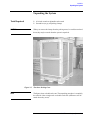
Unpacking the System
Tools Required
•
•
CAUTION
When you remove the clamps from the packing crates, be careful not to bend
them; they may be reused when the system is repacked.
Figure 2-2
NOTE
9/16 inch wrench or adjustable-end wrench
Screwdriver (to pry off packing clamps)
The Outer Packing Crate
The figures show a double rack crate. The unpacking procedure is essentially
the same for either a single rack or a double rack crate (differences will be
noted where they occur).
8510XF Network Analyzer Systems 2-11
Installation
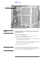
Unpacking the System
Safety Glasses
Figure 2-3
WARNING
Removing the Outer Packing Crate
Always wear safety glasses when removing the clamps and other packing
materials from the crates.
Remove the outer packing crate
1. Remove the clamps holding the packing crate top cover in place.
Remove the top cover and set it aside.
2. Remove the clamps holding the first packing crate wall in place. It does
not matter which wall you remove first.
3. Remove the other walls. Make sure you have people holding the last two
walls in place when you remove the last set of clamps.
4. Set the loading ramp aside for now.
NOTE
In double-rack crates, the heaviest wall is the loading ramp. In single rack
crates, the loading ramp is shipped inside the package, placed on top of the
rack (it is a hinged assembly, shipped in the folded position).
2-12 8510XF Network Analyzer Systems
Installation
Unpacking the System
Foam cover
Figure 2-4
Removing the Foam Cover and Plastic Wrapping
Remove the top cover and plastic wrapping
1. Remove the foam top cover. Save the cover for possible future use.
2. Remove the plastic wrapping from the system.
8510XF Network Analyzer Systems 2-13
Installation
Unpacking the System
Brace bolts (Item A)
Brace (Item B)
Figure 2-5
Removing the Bolts
Ramp anchor bolt (Item D)
Hinged slat (Item C)
Ramp Ledge
Figure 2-6
Removing the Anchor Bolt
2-14 8510XF Network Analyzer Systems
Installation
Unpacking the System
Ramp anchor bolt (Item D)
Ramp end flap
(hinged to ramp) (Item E)
Figure 2-7
Replacing the Anchor Bolt
Unload the system
1. Pull out the two bolts (item A) from the base using a screwdriver or
pliers. See Figure 2-5 on page 2-14.
2. Remove the brace assembly (item B).
3. Lift the hinged slat (item C) and remove the ramp anchor bolt (item D).
See Figure 2-6 on page 2-14.
4. Place one end of the ramp on the ramp ledge. See Figure 2-7 above.
5. Insert the ramp anchor bolt and fold down the hinged slat. To secure the
ramp, you may place long wood screws through the ramp and into the
ramp edge.
6. Fold down the ramp’s end flap (item E).
WARNING
A racked system is tall and top-heavy. It is easy to tip the rack over while
moving it, which could result in personal injury or death. Unloading the system
safely requires the participation of four persons, and they must exercise care
to prevent the rack from tipping over.
8510XF Network Analyzer Systems 2-15
Installation
Unpacking the System
Figure 2-8
Moving the System Down the Ramp
7. Make sure the leveling feet are fully retracted and that the cabinet
casters are rolling freely.
WARNING
Do not stand in front of the rack as it rolls down the ramp.
8. Roll the system down the ramp using extreme care.
9. In case you must move the system in the future, you can retain and reuse
these packing materials or you can purchase replacement packing
materials from Agilent Technologies.
2-16 8510XF Network Analyzer Systems
Installation
Basic System Configurations
Basic System Configurations
The 8510XF can be used in either of two basic configurations, depending on
the means by which the test ports are connected to the device under test.
Coaxial measurement
This configuration is used when the device under test has
coaxial connectors. The 8510XF test ports have 1.0 mm
coaxial connectors, designed to cover a frequency range of
45 MHz to 110 GHz.
In this configuration, the test heads are placed on a work
surface which is attached to the instrument rack, slightly below
the millimeter-wave controller.
The device under test is normally connected to the test ports by
way of coaxial cables. It is also possible to connect the device
to one test port directly, and to the other test port by way of a
coaxial cable.
CAUTION
Do not attempt to connect a test device directly between the two test ports,
without cables. The test heads will not move freely enough to allow such a
connection to be made safely.
Wafer probe measurement
This configuration is used for on-wafer testing; each test port is
connected (through a 1.0 mm coaxial cable, or through an
adapter and another type of coaxial cable) to a wafer test
probe. Contact the manufacturer of the wafer probe station and
an Agilent office for information on the cables and adapters
needed to connect the test heads to the wafer probe station
(refer to “Contacting Agilent” on page -v).
In this configuration, the test heads are placed on X-Y
positioners that are mounted to the wafer probe station.
It is usually best to remove the 8510C from the rack, and place
it on the work surface beside the probe station; this makes it
easier to see the network analyzer’s display and to reach its
front panel controls.
8510XF Network Analyzer Systems 2-17
Installation
Basic System Configurations
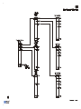
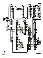
Coaxial Configuration
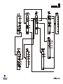
Figure 2-9
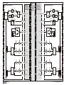
Figure 2-9 shows how the instruments are installed in the rack for the coaxial
configuration. The test heads (which are placed on the work surface) are
omitted here, in order to give an unobstructed view of the rack instruments.
Rack Diagram for Coaxial Configuration
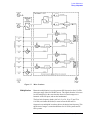
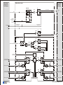
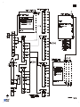
Figure 2-10 on page 2-19 shows rack cabling for the coaxial configuration.
For cabling between the millimeter-wave controller and the test heads, see
“Controller / Test Head Interconnections” on page 2-28.
2-18 8510XF Network Analyzer Systems
Installation
Basic System Configurations
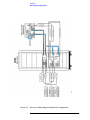
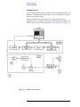
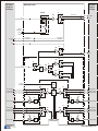
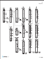
Figure 2-10
Rear-View Cabling Diagram (Coaxial Configuration)
8510XF Network Analyzer Systems 2-19
Installation
Basic System Configurations
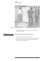
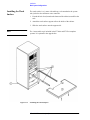
Installing the Work
Surface
The work surface is a 1 meter wide table top, to be attached to the system
rack just below the millimeter-wave controller.
1. Extend the lock feet (located at the bottom of the cabinet) to stabilize the
rack.
2. Attach the work surface support rails to the inside of the cabinet.
3. Slide the work surface onto the support rails.
NOTE
The 1 meter table top is included in the E7340A and E7350A complete
systems. It is optional in the upgrade kits.
Figure 2-11
Installing the Work Surface
2-20 8510XF Network Analyzer Systems
Installation
Basic System Configurations
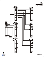
Wafer Probe
Configuration
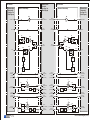
Figure 2-12 shows how the instruments are installed in the rack for the wafer
probe configuration. The test heads (which are placed on X-Y positioners
mounted to the wafer probe station) are omitted here, in order to give an
unobstructed view of the rack instruments.
Figure 2-12
Rack Diagram for Wafer Probe Configuration
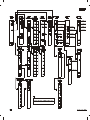
Figure 2-13 shows rack cabling for the wafer probe configuration. For
cabling between the millimeter-wave controller and the test heads, see
“Controller / Test Head Interconnections” on page 2-28.
8510XF Network Analyzer Systems 2-21
Installation
Basic System Configurations
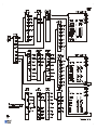
Figure 2-13
Rear-view Cabling Diagram (Wafer-Probe Configuration)
2-22 8510XF Network Analyzer Systems
Installation
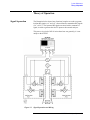
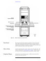
Millimeter-Wave Controller
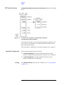
Millimeter-Wave Controller
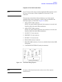
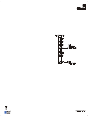
The front panel of the millimeter-wave controller is illustrated below. (See
page 2-28 for information on controller/test head interconnections.)
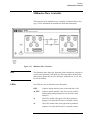
Figure 2-14
Millimeter-Wave Controller
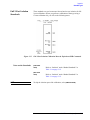
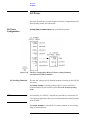
NOTE
The illustration above shows the front panel of the controller as it appears in
systems with Option 005 (.045 MHz to 2 GHz range added). If the system
does not have Option 005, the four “RF Input” connectors (a1, b1, a2, and
b2) will be omitted.
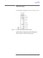
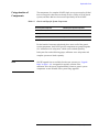
LEDs
Four LEDs are used as indicators on the front panel:
LINE
Lights to indicate that line power to the controller is ON.
ACTIVE
Lights to indicate that this is the active test set (useful in
distinguishing among multiple test sets tied to the same
analyzer).
a1
This LED, located at the upper left of the S-parameter
diagram, is lit when the RF source is switched to Port 1.
a2
This LED, located at the lower right of the S-parameter
diagram, is lit when the RF source is switched to Port 2.
8510XF Network Analyzer Systems 2-23
Installation
Millimeter-Wave Controller
Connectors (Port 1)
RF OUTPUT
This 2.4 mm connector provides the left test head with
the RF signal that is used for frequencies up to 50 GHz.
MM DRIVE
This 2.4 mm connector provides the left test head with
the RF signal that is used for frequencies above 50 GHz
(this signal is multiplied within the test head).
LO OUTPUT
This 3.5 mm connector provides the left test head with
the LO signal that is used for all frequencies.
a1 RF INPUT
This 3.5 mm connector is installed only in systems that
include Option 005; it receives (from the left test head)
the “a1” RF input for frequencies below 2 GHz.
b1 RF INPUT
This 3.5 mm connector is installed only in systems that
include Option 005; it receives (from the left test head)
the “b1” RF input for frequencies below 2 GHz.
BIAS
This multi-pin connector provides power supply voltages
to the left test head.
TEST HEAD
INTERFACE
Connectors (Port 2)
This multi-pin connector provides paths for various
signals between the controller and the left test head
(including 20 MHz IFs from mixers in the test head).
RF OUTPUT
This 2.4 mm connector provides the right test head with
the RF signal that is used for frequencies up to 50 GHz.
MM DRIVE
This 2.4 mm connector provides the right test head with
the RF signal that is used for frequencies above 50 GHz
(this signal is multiplied within the test head).
LO OUTPUT
This 3.5 mm connector provides the right test head with
the LO signal that is used for all frequencies.
a2 RF INPUT
This 3.5 mm connector is installed only in systems that
include Option 005; it receives (from the right test head)
the “a2” RF input for frequencies below 2 GHz.
b2 RF INPUT
This 3.5 mm connector is installed only in systems that
include Option 005; it receives (from the right test head)
the “b2” RF input for frequencies below 2 GHz.
BIAS
This multi-pin connector provides power supply voltages
to the right test head.
TEST HEAD
INTERFACE
This multi-pin connector provides paths for various
signals between the controller and the right test head
(including 20 MHz IFs from mixers in the test head).
2-24 8510XF Network Analyzer Systems
Installation
Millimeter-Wave Controller
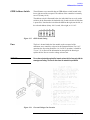
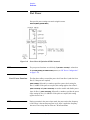
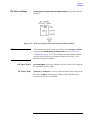
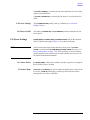
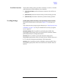
GPIB Address Switch
The millimeter-wave controller has an GPIB address switch located in the
lower right area of the rear panel. The address of the controller is normally
set to 23 (binary 10111).
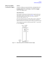
The address switch is illustrated below; the individual bits are set by rocker
switches (in the illustration, the darkened side of each switch is the side that
is pressed in). Note that the switch has the MSB on the right, not the left, so
the selected address (binary 10111) reads, left to right, as “11101”.
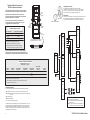
Figure 2-15
GPIB Switch Setting
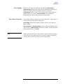
Fuse
The fuse is located inside the line module on the rear panel of the
millimeter-wave controller, as shown in the illustration below. For 110 V
operation, the fuse rating should be 6 A; for 220 V operation, it should be
3 A (or 3.15 A). Review the information on the right of the drawing to
replace the line fuse or to set the voltage selector cam.
WARNING
For continued protection against fire hazard, replace the line fuse only with the
same type and rating. The use of other fuses or materials is prohibited.
Figure 2-16
Fuse and Voltage Cam Location
8510XF Network Analyzer Systems 2-25
Installation
Test Heads
Test Heads
Port 1 and Port 2 are in the left and right test heads, respectively. The test
heads are placed on the work surface in front of the system rack, or (for
on-wafer measurement), on a wafer probe station.
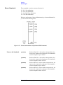
Connector Positions
The test heads are asymmetrical with regard to the positions of the test port
connectors. When the test heads are placed side by side, facing each other,
the Port 1 connector is set further back than the Port 2 connector.
It is usually best to position the left test head slightly forward of the right test
head, so that the test ports are in line. This reduces strain on test cables.
Power Supply Inputs
The test heads do not have their own power supplies; each head receives dc
power supply inputs from the millimeter-wave controller, by way of a
multi-pin interface cable.
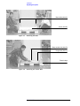
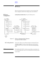
Illustrations
The left test head is illustrated below; it is shown from the rear (that is, from
the point of view of the controller). The multiple-connector panel provides
connections between the test head and the controller (see page 2-28 for
controller/test head interconnections). The single-connector panel contains
test port 1.
Figure 2-17
Left Test Head
2-26 8510XF Network Analyzer Systems
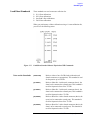
Installation
Test Heads
The right test head is illustrated below; it is shown from the rear (that is,
from the point of view of the controller). The multiple-connector panel
provides connections between the test head and the controller. The
single-connector panel contains test port 2.
Figure 2-18
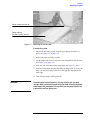
Test Ports
The illustration below shows a test port. The “ON” LED to the left of the test
port lights to indicate that the test head is receiving the required DC supply
voltages from the controller.
Figure 2-19
NOTE
Right Test Head
Test Port
The model number which appears below the test port refers to the
millimeter-wave subsystem, which consists of a millimeter-wave controller
and two test heads (85 GHz or 110 GHz).
8510XF Network Analyzer Systems 2-27
Installation
Controller / Test Head Interconnections
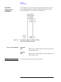
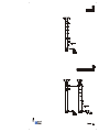
Controller / Test Head Interconnections
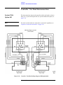
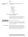
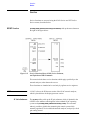
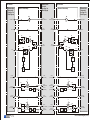
Systems With
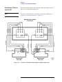
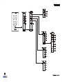
Option 005
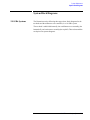
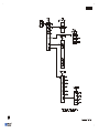
The interconnections between the controller and the test heads are shown
below, for a system with Option 005 (for systems without this option, see
page 2-30).
NOTE
The order in which cables are connected to a test head is significant; see
“Sequence of test head connections” on page 2-29.
Figure 2-20
Controller / Test Head Cabling Diagram (With Option 005)
2-28 8510XF Network Analyzer Systems
Installation
Controller / Test Head Interconnections
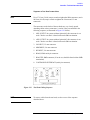
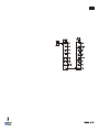
Sequence of test head connections
NOTE
Use a 57 N-cm (5 in-lb) torque wrench to tighten the SMA connectors, and a
90 N-cm (8 in-lb) torque wrench to tighten the 2.4 mm and 3.5 mm
connectors.
The connectors on the backs of the test heads are very closely spaced.
Attaching cables to these connectors is easiest if they are attached in the
following sequence (as illustrated in Figure 2-21 below):
1. b RF OUTPUT; SMA connector
(NOTE: In systems without Option 005, this connector is not used, and
should be fitted with a male SMA termination.)
2. a RF OUTPUT; SMA connector
(NOTE: In systems without Option 005, this connector is not used, and
should be fitted with a male SMA termination.)
3. LO INPUT; 3.5 mm connector
4. MM DRIVE; 2.4 mm connector
5. RF INPUT; 2.4 mm connector
6. BIAS; LEMO multi-pin connector
7. BIAS TEE; SMB connector (if not in use, should be fitted with an SMB
termination)
8. CONTROLLER INTERFACE (multi-pin connector)
Figure 2-21
NOTE
Test Head Cabling Sequence
To remove cables from the test head, use the reverse of the sequence
described above.
8510XF Network Analyzer Systems 2-29
Installation
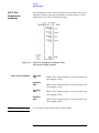
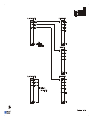
Controller / Test Head Interconnections
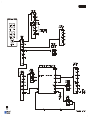
Instruments Without
Option 005
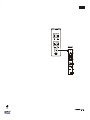
The interconnections between the controller and the test heads are shown
below, for a system without Option 005.
NOTE
The order in which cables are connected to a test head is significant; see
“Sequence of test head connections” on page 2-31.
Figure 2-22
Controller / Test Head Cabling Diagram (Without Option 005)
2-30 8510XF Network Analyzer Systems
Installation
Controller / Test Head Interconnections
Sequence of test head connections
NOTE
Use a 57 N-cm (5 in-lb) torque wrench to tighten the SMA connectors, and a
90 N-cm (8 in-lb) torque wrench to tighten the 2.4 mm and 3.5 mm
connectors.
The connectors on the backs of the test heads are very closely spaced.
Attaching cables to these connectors is easiest if they are attached in the
following sequence (as illustrated in Figure 2-23 below):
1. b RF OUPTUT: In systems without Option 005, this connector is not
used. Check to see that it is fitted with a male SMA termination.
2. a RF OUTPUT: In systems without Option 005, this connector is not
used. Check to see that it is fitted with a male SMA termination.
3. LO INPUT; 3.5 mm connector
4. MM DRIVE; 2.4 mm connector
5. RF INPUT; 2.4 mm connector
6. BIAS; LEMO multi-pin connector
7. BIAS TEE; SMB connector (if not in use, should be fitted with an SMB
termination)
8. CONTROLLER INTERFACE (multi-pin connector)
Figure 2-23
NOTE
Test Head Cabling Sequence
To remove cables from the test head, use the reverse of the sequence
described above.
8510XF Network Analyzer Systems 2-31
Installation
Cable List
Cable List
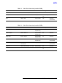
System cabling for the 8510XF is outlined in the tables below.
Duplicate Listings
In these tables, a complete from/to connection list is given for the network
analyzer, the RF source, the LO source, the controller, the left test head, and
the right test head. In other words, each cable is listed twice, and can be
found by looking up the connection from either end. The duplicate listings
make it easier to check the cabling after installation, if a cabling error is
suspected.
In the Notes column, the phrase “duplicate listing” means that the cable has
already been listed once before. The phrase “factory installed” means that
the cable was installed prior to shipment (generally, cables between rack
instruments are factory installed; cables between the millimeter-wave
controller and the test heads are not).
Table 2-7
Cable List (Connections from the 8510C)
From 85101C...
To:
Notes
Cable Type
Part No.
IF/display interconnect
85102B -- IF/display interconnect
factory installed
Multi-pin
08510- 60101
8510 interconnect
Millimeter-wave controller -8510 system bus
factory installed
GPIB
8120-3447
(Model 10833C)
IF/display interconnect
85101C -- IF/display interconnect
factory installed;
duplicate listing
Multi-pin
08510-60101
Test set interconnect
Millimeter-wave controller -- test set
Interconnect
factory installed
Multi-pin
08510-60107
10 MHz in
83651B -- 10 MHz RF output
factory installed
BNC
8120-5370
Trigger in
83651B -- trigger output
factory installed
BNC
8120-5370
From 85102B...
2-32 8510XF Network Analyzer Systems
Installation
Cable List
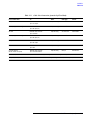
Table 2-8
Cable List (Connections from the 83621B)
From 83621B...
To:
Notes
Cable Type
Part No.
10 MHz ref output
83651B -- 10 MHz ref input
factory installed
BNC
8120-1838
RF output
Millimeter-wave controller -- LO input
factory installed
3.5 mm semi-rigid
coax
E7340-20076
GPIB
83651B -- GPIB
factory installed
GPIB
8120-3444
(Model 10833D)
Table 2-9
Cable List (Connections from the 83651B)
From 83651B...
To:
Notes
Cable Type
Part No.
10 MHZ ref input
83621B -- 10 MHz ref output
factory installed
duplicate listing
BNC
8120-1838
10 MHz ref output
85102B -- 10 MHz in
factory installed
duplicate listing
BNC
8120-5370
Trigger output
85102B -- trigger in
factory installed
duplicate listing
BNC
8120-5370
GPIB
83621B -- GPIB
factory installed
duplicate listing
GPIB
8120-3444
(Model 10833D)
GPIB
Millimeter-wave controller -8510 system bus
factory installed
GPIB
8120-3445
(Model 10833A)
Ext ALC in
Millimeter-wave controller -- ALC output
factory installed
BNC
8120-1839
RF output
Millimeter-wave controller -- RF Input
factory installed
2.4 mm semi-rigid
coax
E7340-20075
8510XF Network Analyzer Systems 2-33
Installation
Cable List
Table 2-10
From Millimeter-Wave Controller,
Front Panel:
To:
Port 1 RF output
Cable List (Connections from the Millimeter-Wave Controller)
Notes
Cable Type
Part No.
Left test head -- RF input
2.4 mm RF flex
E7342-60005
Port 1 mm drive
Left test head -- mm drive
2.4 mm RF flex
E7342-60005
Port 1 LO output
Left test head -- LO input
3.5 mm RF flex
E7342-60004
Port 1 RF input (a1) [Option 005 only]
Left test head -- “a” RF output
SMA RF flex
E7342-60003
Port 1 RF input (b1) [Option 005 only]
Left test head -- “b” RF output
SMA RF flex
E7342-60003
Port 1 bias
Left test head -- bias
DC
E7342-60009
Port 1 test head interface
Left test head -- controller interface
Multi-pin
08510-60126
Port 2 RF output
Right test head -- RF input
2.4 mm RF flex
E7342-60005
Port 2 mm drive
Right test head -- mm drive
2.4 mm RF flex
E7342-60005
Port 2 LO output
Right test head -- LO input
3.5 mm RF flex
E7342-60004
Port 2 RF input (a2) [Option 005 only]
Right test head -- “a” RF output
SMA RF flex
E7342-60003
Port 2 RF input (b2) [Option 005 only]
Right test head -- “b” RF output
SMA RF flex
E7342-60003
Port 2 bias
Right test head -- bias
DC
E7342-60009
Port 2 test head interface
Right test head -- controller interface
Multi-pin
08510-60126
From Millimeter-Wave Controller,
Rear Panel:
LO input
83621B -- RF out
factory installed;
duplicate listing
3.5 mm semi-rigid
coax
E7340-20076
RF input
83651B -- RF out
factory installed;
duplicate listing
2.4 mm semi-rigid
coax
E7340-20075
RF output [Option 006 only]
(Optional RF passthrough output)
ALC output
83651B -- ext ALC in
factory installed;
duplicate listing
BNC
8120-1839
J16 -- not used
(This connector is not used in the 8510XF.)
test set interconnect
85102B -- test set interconnect
factory installed;
duplicate listing
Multi-pin
08510-60107
8510 system bus
85101C -- 8510 interconnect
factory installed;
duplicate listing
GPIB
8120-3447
(Model 10833C)
8510 system bus
83651B -- GPIB
factory installed;
duplicate listing
GPIB
8120-3445
(Model 10833A)
2-34 8510XF Network Analyzer Systems
Installation
Cable List
Table 2-11
Cable List (Connections from the Left Test Head)
From Left Test Head...
To:
Notes
Cable Type
Part No.
LO input
Millimeter-wave controller -port 1 LO Output
duplicate listing
3.5 mm RF flex
E7342-60004
b RF output [Option 005 only]
Millimeter-wave controller -port 1 RF input (b1)
duplicate listing
SMA RF flex
E7342-60003
mm drive
Millimeter-wave controller -port 1 mm drive
duplicate listing
2.4 mm RF flex
E7342-60005
a RF output [Option 005 only]
Millimeter-wave controller -port 1 RF input (a1)
duplicate listing
SMA RF flex
E7342-60003
RF input
Millimeter-wave controller -port 1 RF output
duplicate listing
2.4 mm RF flex
E7342-60005
Bias
Millimeter-wave controller -port 1 bias
duplicate listing
DC
E7342-60009
Controller interface
(NOTE: includes IF outputs)
Millimeter-wave controller -port 1 test head interface
duplicate listing
Multi-pin
08510-60126
Bias tee (SMB)
(For connection to a user-supplied voltage source. No connecting device is provided.)
Test port 1 (1.0 mm)
(For connection to a device under test, directly or through a cable and/or wafer test probe.)
8510XF Network Analyzer Systems 2-35
Installation
Cable List
Table 2-12
Cable List (Connections from the Right Test Head)
From Right Test Head...
To:
Notes
Cable Type
Part No.
LO input
Millimeter-wave controller -port 2 LO Output
duplicate listing
3.5 mm RF flex
E7342-60004
b RF output [Option 005 only]
Millimeter-wave controller -port 2 RF input (b2)
duplicate listing
SMA RF flex
E7342-60003
mm drive
Millimeter-wave controller -port 2 mm drive
duplicate listing
2.4 mm RF flex
E7342-60005
a RF output [Option 005 only]
Millimeter-wave controller -port 2 RF input (a2)
duplicate listing
SMA RF flex
E7342-60003
RF input
Millimeter-wave controller -port 2 RF output
duplicate listing
2.4 mm RF flex
E7342-60005
Bias
Millimeter-wave controller -port 2 bias
duplicate listing
DC
E7342-60009
Controller interface
(NOTE: includes IF outputs)
Millimeter-wave controller -port 2 test head interface
duplicate listing
Multi-pin
08510-60126
Bias tee (SMB)
(For connection to a user-supplied voltage source. No connecting device is provided.)
Test port 2 (1.0 mm)
(For connection to a device under test, directly or through a cable and/or wafer test probe.)
2-36 8510XF Network Analyzer Systems
Installation
Cable List
Other Connections
and Settings
GPIB Addresses
When the 8510C power is turned on, all previously assigned GPIB addresses
are automatically recalled from memory and assigned to the
various system instruments, including the address of the 8510C itself.
The GPIB address switch settings for all instruments must match the
addresses assigned by the system. In 8510XF systems, these addresses are
set at the factory prior to shipment. For reference, the instruments and the
applicable default addresses are listed in the table below.
Table 2-13
Language Switches
8510XF System GPIB Addresses
Instrument
GPIB Address
8510C
16
System Bus
17
83621B LO Source
18
83651B RF Source
19
Millimeter-wave controller
23
Plotter
5
Printer
1
Disk Drive
0
The LANG switches of the 83621B and 83651B sources must be set to 111.
8510XF Network Analyzer Systems 2-37
Installation
Turning On the System
Turning On the System
While turning on the system, be sure to observe all of the precautions stated
on page 2-9.
1. Verify that the hardware is properly connected (refer to “Basic System
Configurations” on page 2-17).
2. Inspect the test ports before they are connected to any other device (see
“Visual inspection” on page 5-4 for information on recognizing defects
in a 1.0 mm connector.)
3. Turn on power for the system rack.
4. Turn on power for all system instruments, except the network analyzer
display unit (the upper portion of the 8510C).
5. Wait 10 seconds, then turn on the network analyzer display unit.
6. The 8510C begins making measurements according to the last recording
of instrument state #8. (Instrument State 8 is recalled each time line
power to the network analyzer is turned on, and each time [USER PRESET]
on the 8510C is pressed.)
2-38 8510XF Network Analyzer Systems
Installation
System Operational Test
System Operational Test
This is a basic operator’s check, designed to establish that the system is
functioning normally. It is not a performance test (the performance
verification procedure for the 8510XF is described in Chapter 4).
This test measures the power levels of four signals within the system, and
compares them to the typical levels that should be present during normal
operation of the system. During the test, you will measure the power levels
of the four user parameters: User 1 (a1), User 2 (b2), User 3 (a2), and User
4 (b1). Measured levels will be compared to the typical levels shown in
Table 2-14 on page 2-41.
User parameters are measurements of the IF input levels received by the
network analyzer. (Figure 2-24 below shows a typical 8510XF user
parameter test plot.) During normal operation of the system, the absolute
level of any IF is much less important than the ratio between one IF and
another. However, the IF levels give a useful indication that the system is
functioning normally.
Figure 2-24
Typical User Parameter Test Plot (User 3, a2)
8510XF Network Analyzer Systems 2-39
Installation
System Operational Test
Test Procedure
Setup
1. Perform a factory preset, using the key sequence:
[RECALL] {MORE} {FACTORY PRESET}
(This sets up the system to measure across its entire frequency range, at
a −15 dBm RF level.)
2. Turn averaging off, using the key sequence:
RESPONSE [MENU] {AVERAGING OFF}
3. Connect shorts to both test ports (for the purposes of this test, any of the
shorts in the 85059A 1.0 mm calibration kit will serve).
Measurement
1. Measure the a1 IF, using the key sequence:
PARAMETER [MENU] {USER 1 a1}
{REDEFINE PARAMETERS} {DRIVE} {PORT1} {REDEFINE DONE}
NOTE
At the default reference level setting (0 dB), the entire trace may not be
visible on the screen. To change the reference value, press
RESPONSE [REF VALUE], and adjust the value using the up/down arrow keys
(−20 dB is the recommended setting). This adjustment will have to be made
repeatedly, because each of the user parameters starts out at the default
reference level.
2. Compare the measured levels with the minimum levels shown in
Table 2-14 on page 2-41.
3. Measure the b1 IF, using the key sequence:
PARAMETER [MENU] {USER 4 b1}
{REDEFINE PARAMETERS} {DRIVE} {PORT1} {REDEFINE DONE}
4. Compare the measured levels with the minimum levels shown in
Table 2-14 on page 2-41.
5. Measure the a2 IF, using the key sequence:
PARAMETER [MENU] {USER 3 a2}
{REDEFINE PARAMETERS} {DRIVE} {PORT2} {REDEFINE DONE}
6. Compare the measured levels with the minimum levels shown in
Table 2-14 on page 2-41.
7. Measure the b2 IF, using the key sequence:
PARAMETER [MENU] {USER 2 b2}
{REDEFINE PARAMETERS} {DRIVE} {PORT2} {REDEFINE DONE}
8. Compare the measured levels with the minimum levels shown in
Table 2-14 on page 2-41.
2-40 8510XF Network Analyzer Systems
Installation
System Operational Test
Conclusion
Table 2-14
If all of the measured levels are at or above the minimum levels shown in
Figure 2-14, this indicates that the 8510XF is functioning normally, and is
ready to be used.
Minimum Levels (All User Parameters)
Frequency Range (GHz)
Minimum Level (dBm)
<2
−63
2 to <18
−38
18 to <50
−58
50 to <75
−61
>75
−63
NOTE: frequencies below 2 GHz are rolled off sharply, owing to the characteristics of the directional
couplers in the test heads.
8510XF Network Analyzer Systems 2-41
Installation
Operating Notes
Operating Notes
Once the system is configured according to the instructions in the previous
section, it is ready for normal operation. The following should be noted:
Frequency Resolution
At test frequencies above 50 GHz, the frequency resolution of the 8510XF is
limited by harmonic multiplication of the RF source. Therefore, some
frequency settings will be slightly modified by the network analyzer
(59.999999996 GHz instead of a requested 60 GHz, for example).
User Parameters
If you are looking at unratioed user parameters (al, bl, a2, b2) you may see a
discontinuity at the beginning and end of the trace, or at band changes.
User Preset
You may press the green [USER PRESET] key at any time to return the network
analyzer to a predefined state. The preset function performs all necessary
internal network analyzer initialization, then recalls Instrument State 8.
[USER PRESET] does not send an initialization signal to the other instruments
on the system bus.
Factory Preset
To re-initialize the network analyzer to the 8510XF factory settings, select
[RECALL] {MORE} {FACTORY PRESET}. This preset initializes all instrument state
functions to their default conditions (except for the frequency range); it also
initializes all instruments on the System Bus.
Power Domain Default
Settings
In the 8510XF, the factory preset default settings for power domain
measurement are as follows:
•
•
IF Frequency Default
Setting
CAUTION
Start: −35 dBm
Stop: −15 dBm
In the 8510XF, the factory preset default value of the network analyzer IF is
20.000017 MHz (in other words, an offset of 17 Hz has been added to the
nominal 20 MHz IF). See “IF Frequency” on page 3-42 for information
about this offset, and instructions on how to modify it.
If the operating system is reloaded, it is necessary to perform the detector
gain calibration (refer to “Detector Gain Calibration” on page 5-6).
2-42 8510XF Network Analyzer Systems
3
Operation
In This Chapter...
•
•
•
•
•
•
•
•
•
•
•
•
NOTE
8510XF Operating System, page 3-2
Menu Changes (Overview), page 3-4
Measurement Calibration, page 3-6
Choosing Calibration Standards, page 3-11
Calibration Types, page 3-13
Standard Types, page 3-20
Port Power, page 3-28
RF Power, page 3-30
LO Power, page 3-36
Service, page 3-38
Alternative 1.0 mm Calibrations, page 3-43
Operation Using a Wafer Probe Station, page 3-46
The functional core of the 8510XF system is the 8510C network analyzer.
Operating the system mainly means operating the analyzer, as described in
the 8510C manuals (see “Finding System Information” on page 1-2). This
chapter is primarily concerned with operational information which is not
found in the 8510C manuals, because it is specific to the 8510XF.
8510XF Network Analyzer Systems 3-1
Operation
8510XF Operating System
8510XF Operating System
In the 8510XF, the network analyzer runs a specially modified version of the
8510C operating system firmware. Some of the user menus are changed as a
result, but the majority of them remain identical to the standard 8510C
menus, as they are described in the 8510C Keyword Dictionary.
The present chapter includes information on the specific areas in which the
standard menus are changed. A complete set of menu maps for the 8510XF,
including equivalent GPIB commands, is presented in Chapter 7, “Menus &
Commands” of this manual.
Checking the
Operating System
The network analyzer is capable of running either the 8510XF version or the
operating system, or the standard 8510C version. You can verify that the
correct version is installed, by using the key sequence:
[SYSTEM] {MORE} {SERVICE FUNCTIONS} {SOFTWARE REVISION}
The name of the displayed revision should begin with “8510XF,” not
“8510C.”
The appropriate (CRT or LCD) 8510XF version of the operating system is
installed at the factory; it can be re-loaded, if necessary, from a diskette
(Agilent part number E7340-10001) that is supplied with the system.
The appropriate (CRT or LCD) 8510C version of the operating system can
be loaded, if necessary, from a diskette supplied with the accessories to the
8510C (Agilent part number 85101-80116).
NOTE
To load the operating system, use the key sequence: [SYSTEM] {MORE}
to call up the main service functions menu,
and enter [1][9] [=MARKER] to select LOAD PROGRAM DISK.
{SERVICE FUNCTIONS} {TEST MENU}
3-2 8510XF Network Analyzer Systems
Operation
8510XF Operating System
Menu Conventions
Used in this Chapter
Softkeys
The names of softkeys are represented in italics, to distinguish them from
keys that are marked with a permanent title. For example, the sequence
[CAL] {MORE} {SET Z0} means “press the [CAL] key, followed by the {MORE}
softkey and the {SET Z0} softkey.”
Menu Illustrations
In this chapter, several menus are illustrated with excerpts from the menu
maps which are shown (in their entirety) in Chapter 7. These menu maps
show both the softkeys and (to the right of the menu rectangle) the
equivalent GPIB commands, if any.
In the menu illustration below, the softkey names (as they are displayed on
the screen of the network analyzer) are shown within the rectangle; the
GPIB commands that are equivalent to these softkeys are shown to the right
of the rectangle. For example, the GPIB command “REFL” is equivalent to
the softkey {REFLECT’N}.
Figure 3-1
Illustration of a Menu with GPIB Commands at Right
8510XF Network Analyzer Systems 3-3
Operation
8510XF Operating System
Menu Changes
(Overview)
CAL Menu
The [CAL], [DOMAIN], [PARAMETER], STIMULUS [MENU], and [SYSTEM] menus have all
been modified for the 8510XF, as noted briefly below.
The [CAL] menu is changed in the following areas:
•
•
{TRIM SWEEP}
is deleted.
The contents of the [CAL] menu (and most of its submenus) reflect the
name of the calibration kit that is in use, as well as the names of the
calibration standards in that kit. A calibration kit (85059A) has been
developed specifically for the 8510XF; the menu maps in Chapter 7
reflect the contents of that kit.
The [CAL] menu and its submenus are discussed later in this chapter (see
“Calibration Types” on page 3-13).
DOMAIN Menu
The [DOMAIN] menu is changed as follows:
{PULSE PROFILE}
PARAMETER Menu
The [PARAMETER] menu is changed as follows:
{PHASE LOCK}
STIMULUS Menu
is deleted.
is deleted.
STIMULUS [MENU]
is changed in the following areas:
•
The submenu called up by the {POWER} softkey is substantially revised.
{ATTENUATOR PORT 1}, {ATTENUATOR PORT 2}, and {POWER FLATNESS} are
deleted. Also, new port power functions are added (see “Port Power” on
page 3-28).
•
•
{RAMP}
is deleted.
{COUPLED CHANNELS}
and {UNCOUPLED CHANNELS} are deleted.
3-4 8510XF Network Analyzer Systems
Operation
8510XF Operating System
SYSTEM Menu
The [SYSTEM] menu is changed in the following areas:
•
•
{PULSE CONFIG} is
•
•
{SYSTEM PHASELOCK} is
deleted.
is deleted (but see {SERVICE FUNCTIONS} {IF GAIN} below,
which replaces part of the functionality of {EDIT MULT. SRC.}).
{EDIT MULT. SRC.}
{POWER LEVELING}
deleted.
is deleted (but see {RF POWER CONFIG} and
{LO POWER CONFIG} below).
•
•
•
•
{RF POWER CONFIG}
is added (see “RF Power” on page 3-30).
{LO POWER CONFIG}
is added (see “LO Power” on page 3-36).
{IF FREQ} is added. This function makes it possible to specify the IF
frequency (nominally 20 MHz) that is used by he network analyzer (see
“IF Frequency” on page 3-42).
The menu called up by {SERVICE FUNCTIONS} is substantially revised:
❍
❍
•
•
is moved to the {85102 SERVICE} menu (see below).
{PEEK/POKE LOCATION}, {PEEK}, and {POKE} are deleted (but are
duplicated under the {85102 SERVICE} and {XF TEST SET SERVICE} menus
(see below).
{IF GAIN}
{85102 SERVICE} is
added (see “Service” on page 3-38).
{XF TEST SET SERVICE} is
added (see “Service” on page 3-38).
8510XF Network Analyzer Systems 3-5
Operation
Measurement Calibration
Measurement Calibration
Why Calibration Is
Essential
During measurement calibration, a standard device with known
characteristics is measured, and the results of the measurement are used to
create a set of error coefficients. During subsequent measurements, the
network analyzer uses the error coefficients to correct for its own
measurement errors.
The accuracy of the network analyzer is very much dependent on this
error-correction technique; therefore, the analyzer must be calibrated before
it is used to make measurements.
When to Repeat the
Calibration
Checking the
Calibration
The 8510XF is designed for exceptional stability; after it has been
calibrated, the specified measurement accuracy of the system is guaranteed,
provided that the conditions of measurement remain the same. However,
certain changes to the measurement conditions may invalidate the
calibration, as described below.
•
A calibration is only valid for the frequency range over which it was
performed; if the frequency range has changed, the calibration must be
repeated.
•
A calibration is only valid for the number of points over which it was
performed; if the number of points has been increased, the calibration
must be repeated.
•
If test port cables have been kinked, replaced, or disconnected and
reconnected, the calibration may be invalid, and should be checked.
•
If connectors have been degraded by wear, the calibration may be
invalid, and should be checked.
•
If the ambient temperature changes by ±1 °C or more, the calibration
may be invalid, and should be checked.
A common practice for making a rough check of a calibration is to
remeasure one of the devices used in the calibration procedure (or
verification procedure). For example, if you reconnect a short that was used
during calibration, it should appear as a near-perfect short, across the
frequency range of calibration.
3-6 8510XF Network Analyzer Systems
Operation
Measurement Calibration
NOTE
The shorts used in the 85059A 1.0 mm calibration kit are offset shorts.
When measured, the offset shorts will exhibit the characteristics of a flush
short that is placed at the end of an airline (there will be a change in phase
and an increasing amount of loss with increasing frequency).
Another practice is to measure a device that had been measured with a
previous good calibration, and compare the present measurement to the
earlier one (if there are any changes exceeding the limits of acceptable
accuracy, a new calibration is needed). For example, measure one of the
verification devices that was used during performance verification, and
compare it to the data that was taken at that time.
However, these methods give only an approximate confirmation that the
calibration is good. The only way to make an accurate check is to run the
8510C Specification and Performance Verification software, which runs on a
PC or controller (the procedure for this is presented in Chapter 4,
“Performance Verification”).
Calibration
Techniques
A variety of calibration techniques can be used with the 8510XF, including
the following:
•
•
•
•
SOLT (Short-Open-Load-Thru)
Offset Shorts (Shorts with different offset lengths)
TRL (Thru-Reflect-Line)
TRM (Thru-Reflect-Match)
The calibration technique used depends in part on the type of calibration kit
used. The 1.0 mm calibration kit (85059A), which was designed specifically
for the 8510XF, uses a combination of two calibration techniques (SOLT
calibration, for frequencies up to 50 GHz, and Offset Shorts calibration, for
frequencies above 50 GHz). This combination of techniques provides the
best possible calibration results on the 8510XF.
Types of Calibration
Kits
1.0 mm calibration kit
NOTE
If a calibration kit other than the 85059A is used, please refer to the
documentation for that kit.
The calibration procedures in this chapter are based on the assumption that
the 1.0 mm coaxial calibration kit (85059A) will be used to calibrate the
system. This kit was designed specifically for the 8510XF, and provides
coverage over a frequency range of 45 MHz to 110 GHz. (The standards in
the kit have 1.0 mm coaxial connections; they cannot be used for on-wafer
measurement calibration.) Refer to the 85059A calibration kit manual for
more information (part number 85059-90003).
8510XF Network Analyzer Systems 3-7
Operation
Measurement Calibration
The 1.0 mm calibration kit also supports two quick calibration techniques,
which can be used in certain situations where measurement accuracy is not
critical; for details, see “Alternative 1.0 mm Calibrations” on page 3-43.
Other coaxial calibration kits
It is possible to use other coaxial calibration kits with the 8510XF, provided
that appropriate adapters are connected to the 1.0 mm test ports. However,
this type of calibration will not cover the entire frequency range of the
8510XF.
For example, a 2.4 mm coaxial calibration kit could be used, provided that
adapters (1.0 mm to 2.4 mm) were connected to the test ports. However, this
would prevent the system from making calibrated measurements above
50 GHz.
On-wafer calibration
When the 8510XF is configured for on-wafer measurement, the calibration
process must be adapted to the accessories that are being used (including the
on-wafer calibration standards). See “Operation Using a Wafer Probe
Station” on page 3-46.
3-8 8510XF Network Analyzer Systems
Operation
Calibration Procedure
Calibration Procedure
NOTE
The following procedure assumes that the 1.0 mm calibration kit (85059A)
will be used to calibrate the 8510XF.
Load Calibration
Constants
Before you can calibrate the system, you must load the appropriate
calibration constants into the system.
1. Insert the calibration data disk (included with the 1.0 mm calibration kit)
into the 8510C disk drive.
2. Press [DISC] {LOAD}.
The analyzer displays SELECT DATA TYPE TO LOAD.
3. Select {CAL KIT 1} or {CAL KIT 2}.
The analyzer displays USE KNOB OR STEP KEYS TO SELECT A FILE.
4. Select CK_1MMA1A from the display menu.
(This file is the recommended choice for normal operation; the other file,
CK_1MMA1B, is discussed under “Broadband Standards” on page 3-43).
5. Select {LOAD FILE}. This loads the calibration constants into the memory
of the network analyzer. A screen message indicates when the load
process is complete (FILE ‘CK_1MMA1A’ LOADED FROM DISK).
6. Remove the disk from the drive.
Set Up the Analyzer
1. Set the desired frequency range for the calibration, using the STIMULUS
keys.
2. Select step mode, using STIMULUS [MENU] {STEP}.
3. Set the desired number of points, using STIMULUS [MENU]
{NUMBER OF POINTS}.
4. Set the desired averaging value, using RESPONSE [MENU]
{AVERAGING ON/restart}.
5. Be sure that the system impedance is set to 50Ω, by pressing:
[CAL] {MORE} {SET Z0}
(If the display does not read 50.0Ω, press: [5] [0] [X1].)
6. Press [CAL] {CAL 1} or {CAL 2}
8510XF Network Analyzer Systems 3-9
Operation
Calibration Procedure
7. Select a calibration type from the menu. The available types are:
❍
❍
❍
❍
❍
❍
❍
Response
Response & Isol’n
S11 1-Port
S22 1-Port
One-Path 2-Port
Full 2-Port
TRL 2-Port [actually TRM 2-port, in the case of the 8510XF]
8. The appropriate calibration submenu will appear, listing the calibration
standards that are needed for the selected calibration type. (For many
types of calibration, the standards are listed on sub-submenus, sorted by
categories such as “Shorts” or “Transmission”.)
Connect and Measure
the Calibration
Standards
1. The standards listed on the calibration-type submenu are all of the
standards that apply to that particular type of calibration. Among these
possibilities, determine which standards are appropriate to the frequency
range being calibrated (and also appropriate to the sex of the test port or
cable). See “Choosing Calibration Standards” on page 3-11.
2. Starting from the top down, connect the first standard that is appropriate
to the calibration.
3. Select the softkey associated with the standard, and wait for the 8510XF
to complete its calibration run for that standard (the softkey name will be
underlined when the calibration run is complete).
4. Disconnect the standard (unless the same standard, connected to the
same port, is needed for the next step).
5. Repeat steps 2 through 4 until all appropriate standards shown on the
menu have been measured and are underlined.
6. When all appropriate standards on the menu have been measured and are
underlined, select the {DONE} or {SAVE} softkey at the bottom of the menu.
a. If the menu includes a {DONE} softkey, this indicates that this
submenu is complete, but the calibration as a whole is not. Selecting
this softkey leads back to the menu that still needs to be completed.
b. If the menu includes a {SAVE} softkey, no other calibration submenus
are required to complete the calibration. Selecting this softkey saves
the calibration.
3-10 8510XF Network Analyzer Systems
Operation
Choosing Calibration Standards
Choosing Calibration Standards
Connector Sex
The connector sex of a 1.0 mm calibration standard can have a significant
effect on its electrical characteristics. Many of the standards in the 1.0 mm
calibration kit have separate standard definitions for male and female
versions. It is very important to use the correct definition for the sex of the
standard you are measuring.
NOTE
The standard labels which appear in the calibration menus specify connector
sex as “(M)” or “(F)”. The parentheses around the sex designator mean that
it refers to the sex of the port to which the standard is connected (not the sex
of the standard itself).
For example:
•
•
•
Offset Shorts
“(M) OPEN” means an open that connects to a male port (in other
words, the open itself has a female connector).
“(F) SHORT” means a short that connects to a female port (in other
words, the short itself has a male connector).
Whenever a device is described as “M” or “F” without parentheses, the
letter indicates the sex of the device itself.
In the 8510XF, at frequencies above 50 GHz, offset shorts are used in the
place of opens and loads. The “OPEN” category is therefore renamed
“OPEN/SHORT”, and the “LOAD” category is renamed “LOAD/SHORT”.
The offset shorts that are included in the 1.0 mm calibration kit have
different offset lengths. To distinguish them clearly, each offset short is
assigned a number (1 to 4), and that many rings are engraved on the body of
the device (that is, Short 2 has two rings, and Short 4 has four rings).
The offset shorts have different standard definitions for the versions with
male or female connectors. For example, when using Short 3, the standard
definition to use is “(M) SHORT3”, if the device is connected to a male port,
or “(F) SHORT3” if it is connected to a female port.
8510XF Network Analyzer Systems 3-11
Operation
Choosing Calibration Standards
Banded Standards
Table 3-1
Some of the calibration standards in the 1.0 mm calibration kit are limited to
a particular frequency band. Calibration standards that are limited in this
way are shown in Table 3-1 below. During the calibration process, be sure to
use all the standards that are needed to cover the frequency range in which
you will be making measurements. Refer to the 85059A calibration kit
manual for more information.
Banded Standards
∀
Standard Type
.045 to 50 GHz
50 to 75 GHz
75 to 110 GHz
Combined Ranges
“Open/Short”
(M) OPEN
(F) OPEN
(M) SHORT3
(F) SHORT3
(M) SHORT3
(F) SHORT3
(combine the standards
shown in the columns to
the left, as appropriate)
“Shorts”
(M) SHORT3
(F) SHORT3
(M) SHORT1
(F) SHORT1
(M) SHORT1
(F) SHORT1
(combine the standards
shown in the columns to
the left, as appropriate)
“Load/Short”
50GHZ LOAD
(M) SHORT4
(F) SHORT4
(M) SHORT2
(F) SHORT2
(combine the standards
shown in the columns to
the left, as appropriate)
“Match” (TRL/TRM
Calibration)
50GHZ LOAD
(both ports)
N/A
N/A
(TRM calibration is not
used above 50 GHz)
“Isolation”
50 GHz LOAD
Load BB1
Load BB1
Load BB1
1. The broadband load is a combination of a lossy delay line plus a 50 GHz load (refer to the 85059A calibration kit manual).
Non-Banded
Standards
Other standards in the 1.0 mm calibration kit, which are not limited to a
particular frequency range, are shown in Table 3-2 below. The right column
of the table refers to some devices that were also listed in Table 3-1; here
they are used differently. For example, Short No. 3 was limited to 50 GHz as
a “Shorts” standard, but not when it is used as a “Response” standard.
Table 3-2
Calibration Standards Used at All Frequencies
∀
Standard Types
Device or Connection
“Response” (for S11 or S22)
Choose one of the following:
• (M) SHORT3 or (F) SHORT3
• (M) OPEN or (F) OPEN
“Response” (for S21 or S12)
• THRU (connect Port 1 to Port 2 via cable)
“S11REFLECT SHORT” (TRL menu)
Connect a short to Port 1:
(M) SHORT3 or (F) SHORT3
“S22REFLECT SHORT” (TRL menu)
Connect a short to Port 2:
(M) SHORT3 or (F) SHORT3
“THRU” (various menus)
Connect Port 1 to Port 2 via cable
3-12 8510XF Network Analyzer Systems
Operation
Calibration Types
Calibration Types
Selecting [CAL] {CAL 1} or [CAL] {CAL 2} will call up the Calibration Type menu:
Figure 3-2
CAL TYPE Menu & Equivalent GPIB Commands
All of these softkeys, except for the first, represent different types of
calibration. Each type of calibration requires its own particular set of
calibration standards, as described in the following pages.
8510XF Network Analyzer Systems 3-13
Operation
Calibration Types
Response
This is a very limited calibration, which corrects only for frequency
response, not for directivity or source match errors. The performance of the
8510XF is not specified, if this calibration is used. To perform this
calibration using the 1.0 mm calibration kit, select:
[CAL] {CAL1 or CAL2} {CALIBRATE: RESPONSE}
This calls up the response standard select menu, as shown on the right of the
illustration below:
Figure 3-3
Select ONE of the
Response Standards
Response Menu (Right) & Equivalent GPIB Commands
For Reflection Measurements (S11, S22), select one of the following:
{(F) SHORT3}
Refers to offset short No. 3 with a male connector (that
is, the short is to be connected to a female port).
{(F) OPEN}
Refers to an open with a male connector (that is, the open
is to be connected to a female port).
{(M) SHORT3}
Refers to offset short No. 3 with a female connector (that
is, the short is to be connected to a male port).
{(M) OPEN}
Refers to an open with a female connector (that is, the
open is to be connected to a male port).
For Transmission Measurements (S12, S21), select:
{THRU}
Connect Port 1 to Port 2 by way of a cable.
3-14 8510XF Network Analyzer Systems
Operation
Calibration Types
Response & Isolation
This is a very limited calibration, which corrects only for frequency response
and isolation, not for directivity or source match errors. The performance of
the 8510XF is not specified, if this calibration is used. To perform this
calibration using the 1.0 mm calibration kit, select:
[CAL] {CAL1 or CAL2} {RESPONSE & ISOL’N}
This will call up the menu and submenu shown below:
Figure 3-4
Select ONE of the
Response Standards
Response & Isolation Menu, Response Menu, and Equivalent GPIB
Commands
For Reflection Measurements (S11, S22), select one of the following:
{(F) SHORT3}
Refers to offset short No. 3 with a male connector (that
is, the short is to be connected to a female port).
{(F) OPEN}
Refers to an open with a male connector (that is, the open
is to be connected to a female port).
{(M) SHORT3}
Refers to offset short No. 3 with a female connector (that
is, the short is to be connected to a male port).
{(M) OPEN}
Refers to an open with a female connector (that is, the
open is to be connected to a male port).
For Transmission Measurements (S12, S21), select:
{THRU}
Isolation Standard
{ISOL’N STD
LOAD}
Connect Port 1 to Port 2 by way of a cable.
Refer to “Isolation” under “Banded Standards” in
Table 3-1 on page 3-12.
8510XF Network Analyzer Systems 3-15
Operation
Calibration Types
S11 1-Port
This calibration is for reflection measurements using the left test port (within
those operational limits, however, it is a thorough and accurate calibration).
To perform this calibration using the 1.0 mm calibration kit, select:
[CAL] {CAL1 or CAL2} {S11 1-PORT}
This calls up the following menu:
Figure 3-5
S11 1-Port Menu & Equivalent GPIB Commands
For notes on the three types of standards involved in this calibration, see the
following:
•
•
•
S22 1-Port
“Open/Short Standards” on page 3-21
“Shorts Standards” on page 3-22
“Load/Short Standards” on page 3-23
This calibration is for reflection measurements using the right test port
(within those operational limits, however, it is a thorough and accurate
calibration). To perform this calibration using the 1.0 mm calibration kit,
select:
[CAL] {CAL1 or CAL2} {S22 1-PORT}
This calls up a menu which is identical to the one shown in Figure 3-5
above, except that it is identified as S22 rather than S11.
3-16 8510XF Network Analyzer Systems
Operation
Calibration Types
One Path 2-Port
This calibration is for reflection and transmission measurements, in one
direction only (with Port 1 defined as the source). To perform this calibration
using the 1.0 mm calibration kit, select:
[CAL] {CAL1 or CAL2} {ONE PATH 2-PORT}
This calls up the following menu:
Figure 3-6
Notes on the Standards
One Path 2-Port Menu & Equivalent GPIB Commands
These are the same standards that are used for the S11
and S22 1-port calibrations, except that in this case both
ports are calibrated. The reflection standards are sorted
into three categories:
{REFLECT’N}
•
•
•
See “Open/Short Standards” on page 3-21
See “Shorts Standards” on page 3-22
See “Load/Short Standards” on page 3-23
{TRANSMISSION}
See “One-Path Transmission Standards” on page 3-24.
{ISOLATION}
See “One-Path Isolation Standard” on page 3-25.
8510XF Network Analyzer Systems 3-17
Operation
Calibration Types
Full 2-Port
This is a very thorough calibration, which takes measurements of reflection,
transmission, and isolation for both ports. This type of calibration (when
performed using the 1.0 mm calibration kit) combines the SOLT calibration
technique (for frequencies up to 50 GHz) with the Offset Shorts calibration
technique (for frequencies above 50 GHz). This combination yields the best
possible calibration results, for measurement over the full frequency range
of the 8510XF.
For this calibration, select:
[CAL] {CAL1 or CAL2} {FULL 2-PORT}
This calls up the following menu:
Figure 3-7
Notes on the Standards
Full 2-Port Menu & Equivalent GPIB Commands
These are the same standards that are used for the S11
and S22 1-port calibrations, except that in this case both
ports are calibrated. The reflection standards are sorted
into three categories:
{REFLECT’N}
•
•
•
See “Open/Short Standards” on page 3-21
See “Shorts Standards” on page 3-22
See “Load/Short Standards” on page 3-23
{TRANSMISSION}
See “Full 2-Port Transmission Standards” on page 3-26.
{ISOLATION}
See “Full 2-Port Isolation Standards” on page 3-27.
3-18 8510XF Network Analyzer Systems
Operation
Calibration Types
TRL (TRM) 2-Port
The 1.0 mm calibration kit does not include a precision transmission line;
therefore a TRM (Thru-Reflect-Match) calibration must be used in place of
the TRL (Thru-Reflect-Line) calibration indicated by the menu title.
NOTE
The 1.0 mm calibration kit only supports TRM 2-port calibration for
measurement up to 50 GHz.
For this calibration, select:
[CAL] {CAL1 or CAL2} {TRL 2-PORT}
Figure 3-8
Notes on the Standards
TRL 2-Port Menu & Equivalent GPIB Commands
{THRU}
{S11 REFLECT
SHORT}
{S22 REFLECT
SHORT}
Connect Port 1 to Port 2.
Connect a short to Port 1. You will be prompted to select
{(F) SHORT3} or {(M) SHORT3}.
Connect a short to Port 2. You will be prompted to select
{(F) SHORT3} or {(M) SHORT3}.
{ISOLATION
LOAD}
See “Full 2-Port Isolation Standards” on page 3-27.
{LINE MATCH
MATCH}
Connect 50 GHz loads to Port 1 and Port 2.
{LOWBAND
REFLECT’N}
This standard is not used in connection with the 1.0 mm
calibration kit (for information regarding its use with
other calibration kits, see the manuals for those kits).
8510XF Network Analyzer Systems 3-19
Operation
Standard Types
Standard Types
Standards Already
Described
Other Standards
Some of the standards have already been described, in connection with the
calibration types with which they are associated.
•
Response standards (required for Response calibrations) are described
on page 3-14.
•
Response & Isolation standards (required for Response & Isolation
calibrations) are described on page 3-15.
•
TRM standards (required for Thru-Reflect-Match calibrations) are
described on page 3-19.
The remaining standard types require a more detailed presentation, and are
described in the following pages.
3-20 8510XF Network Analyzer Systems
Operation
Standard Types
Open/Short Standards
These standards are used to measure reflection for:
•
•
•
•
S11 1-Port calibrations
S22 1-Port calibrations
One-Path 2-Port calibrations
Full 2-Port calibrations
When you perform any of these calibrations using a 1.0 mm calibration kit,
you will see the following menu:
Figure 3-9
Notes on the Standards
Open/Short Standard Menu & Equivalent GPIB Commands
{(F) OPEN}
Refers to an open which has a male connector (that is, the
open is to be connected to a female port). This standard is
used for frequencies up to 50 GHz.
{(F) SHORT3}
Refers to Short No. 3 with a male connector (that is, the
short is to be connected to a female port). This standard is
used for frequencies above 50 GHz.
{(M) OPEN}
Refers to an open which has a female connector (that is,
the open is to be connected to a male port). This standard
is used for frequencies up to 50 GHz.
{(M) SHORT3}
Refers to Short No. 3 with a female connector (that is, the
short is to be connected to a male port). This standard is
used for frequencies above 50 GHz.
8510XF Network Analyzer Systems 3-21
Operation
Standard Types
Shorts Standards
These standards are used to measure reflection for:
•
•
•
•
S11 1-Port calibrations
S22 1-Port calibrations
One-Path 2-Port calibrations
Full 2-Port calibrations
When you perform any of these calibrations using a 1.0 mm calibration kit,
you will see the following menu:
Figure 3-10
Notes on the Standards
Shorts Standard Menu & Equivalent GPIB Commands
{(F) SHORT3}
Refers to Short No. 3 with a male connector (that is, the
short is to be connected to a female port). This standard is
used for frequencies up to 50 GHz.
{(F) SHORT1}
Refers to Short No. 1 with a male connector (that is, the
short is to be connected to a female port). This standard is
used for frequencies above 50 GHz.
{(M) SHORT3}
Refers to Short No. 3 with a female connector (that is, the
open is to be connected to a male port). This standard is
used for frequencies up to 50 GHz.
{(M) SHORT1}
Refers to Short No. 1 with a female connector (that is, the
short is to be connected to a male port). This standard is
used for frequencies above 50 GHz.
3-22 8510XF Network Analyzer Systems
Operation
Standard Types
Load/Short Standards
These standards are used to measure reflection for:
•
•
•
•
S11 1-Port calibrations
S22 1-Port calibrations
One-Path 2-Port calibrations
Full 2-Port calibrations
When you perform any of these calibrations using a 1.0 mm calibration kit,
you will see the following menu:
Figure 3-11
Notes on the Standards
Load/Short Standard Menu & Equivalent GPIB Commands
{50GHz LOAD}
Refers to either of two 50 GHz loads (with male and
female connectors, as appropriate). This standard is used
for frequencies up to 50 GHz.
{(F) SHORT4}
Refers to Short No. 4 with a male connector (that is, the
short is to be connected to a female port). This standard is
used for frequencies from 50 to 75 GHz.
{(F) SHORT2}
Refers to Short No. 2 with a male connector (that is, the
short is to be connected to a female port). This standard is
used for frequencies above 75 GHz.
{(M) SHORT4}
Refers to Short No. 4 with a female connector (that is, the
open is to be connected to a male port). This standard is
used for frequencies from 50 to 75 GHz.
{(M) SHORT2}
Refers to Short No. 2 with a female connector (that is, the
short is to be connected to a male port). This standard is
used for frequencies above 75 GHz.
8510XF Network Analyzer Systems 3-23
Operation
Standard Types
One-Path
Transmission
Standards
These standards are used to measure transmission and match for one-path
2-port calibrations. When you perform a calibration of that type using a
1.0 mm calibration kit, you will see the following menu:
Figure 3-12
Notes on the Standards
One-Path Transmission Calibration Menu
& Equivalent GPIB Commands
{FWD.TRANS.
THRU}
{FWD.MATCH
THRU}
NOTE
Make a “thru” connection (that is, connect one port to the
other through a cable).
Make a “thru” connection (that is, connect one port to the
other through a cable).
It is necessary to make both of these measurements.
3-24 8510XF Network Analyzer Systems
Operation
Standard Types
One-Path Isolation
Standard
Figure 3-13
Note on the Standard
NOTE
This standard is used to measure forward isolation for one-path 2-port
calibrations. When you perform a calibration of that type using a 1.0 mm
calibration kit, you will see the following menu:
One-Path Isolation Calibration Menu & Equivalent GPIB Commands
{FWD ISOL’N
LOAD}
Refer to “Isolation” under “Banded Standards” in
Table 3-1 on page 3-12.
To skip the isolation part of the calibration, select {OMIT ISOLATION}.
8510XF Network Analyzer Systems 3-25
Operation
Standard Types
Full 2-Port
Transmission
Standards
These standards are used to measure transmission and match for full 2-port
calibrations. When you perform a calibration of that type using a 1.0 mm
calibration kit, you will see the following menu:
Figure 3-14
Notes on the Standards
Full 2-Port Transmission Calibration Menu
& Equivalent GPIB Commands
{FWD. TRANS.
THRU}
{FWD.MATCH
THRU}
{REV.TRANS.
THRU}
{REV.MATCH
THRU}
NOTE
Make a “thru” connection (that is, connect one port to the
other through a cable).
Make a “thru” connection (that is, connect one port to the
other through a cable).
Make a “thru” connection (that is, connect one port to the
other through a cable).
Make a “thru” connection (that is, connect one port to the
other through a cable).
It is necessary to make all four of these measurements.
3-26 8510XF Network Analyzer Systems
Operation
Standard Types
Full 2-Port Isolation
Standards
Figure 3-15
Notes on the Standards
These standards are used to measure forward and reverse isolation for full
2-port calibrations. When you perform a calibration of that type using a
1.0 mm calibration kit, you will see the following menu:
Full 2-Port Isolation Calibration Menu & Equivalent GPIB Commands
{FWD ISOL’N
LOAD}
{REV ISOL’N
LOAD}
NOTE
Refer to “Isolation” under “Banded Standards” in
Table 3-1 on page 3-12.
Refer to “Isolation” under “Banded Standards” in
Table 3-1 on page 3-12.
To skip the isolation part of the calibration, select {OMIT ISOLATION}.
8510XF Network Analyzer Systems 3-27
Operation
Port Power
Port Power
Port-specific power settings are made using this menu:
STIMULUS [MENU] {POWER MENU}
Figure 3-16
NOTE
Port 1 Power Functions
Power Menu & Equivalent GPIB Commands
The port power functions are valid only if {RF LEVEL / SYSTEM} is selected on
the [SYSTEM] {MORE} {RF POWER CONFIG} menu (see “RF Power Configuration”
on page 3-30).
The first three softkeys control the power level from Port 1 (and also from
Port 2, if the ports are coupled).
{PORT1 POWER},
followed by a number, specifies a power level setting for
Port 1, in dBm. If the ports are coupled, this setting applies also to Port 2.
and {PORT1 SLOPE OFF} are used to enable and disable power
slope for Port 1. {PORT1 SLOPE ON}, followed by a number, specifies the power
slope setting for Port 1, in dB/GHz. If the ports are coupled, this setting
applies also to Port 2.
{PORT1 SLOPE ON}
NOTE
During operation in the power slope mode, the power at the first frequency
of the sweep is the current port power level; slope is applied as frequency
increases. Power slope has no effect on CW measurements.
3-28 8510XF Network Analyzer Systems
Operation
Port Power
Port Coupling
Port 2 Power Functions
Softkey #4 is a toggle key, alternately representing {COUPLE PORTS} or
{UNCOUPLE PORTS}. Pressing this softkey selects the displayed function, but
changes the display to show the opposite function. If you press
{COUPLE PORTS}, the Port 1 power level setting and power slope setting are
applied to Port 2. If you press {UNCOUPLE PORTS}, the two ports have
independent power level settings and power slope settings.
The last three softkeys control the power level from Port 2. These softkeys
are displayed only if the ports are uncoupled.
{PORT2 POWER},
followed by a number, specifies a power level setting for
Port 2, in dBm.
and {PORT2 SLOPE OFF} are used to enable and disable power
slope for Port 2. {PORT2 SLOPE ON}, followed by a number, specifies the power
slope setting for Port 2, in dB/GHz.
{PORT2 SLOPE ON}
NOTE
During operation in the power slope mode, the power at the first frequency
of the sweep is the current port power level; slope is applied as frequency
increases. Power slope has no effect on CW measurements.
8510XF Network Analyzer Systems 3-29
Operation
RF Power
RF Power
RF power functions that are not port-specific are accessed using the RF
Power Configuration and RF Power Settings menus, described below.
RF Power
Configuration
[SYSTEM] {MORE} {RF POWER CONFIG}
Figure 3-17
RF Leveling Functions
calls up the following menu:
RF Power Configuration Menu, Submenus,
and Equivalent GPIB Commands
The first four softkeys specify different methods of controlling RF power.
If {RF LEVEL / SYSTEM} is selected, leveling of RF power at the test ports is
controlled entirely by the 8510XF system. This is the normal operating
mode.
NOTE
The remaining “RF LEVEL” selections are provided as a convenience for
use in unusual applications; they are not recommended for normal operation
of the 8510XF.
3-30 8510XF Network Analyzer Systems
Operation
RF Power
If {RF LEVEL / INTERNAL} is selected, the RF source (83651B) performs its own
leveling, using an internal detector.
•
•
To use the {RF LEVEL / INTERNAL} mode, you must break the connection
between the ALC output of the millimeter-wave controller and the ALC
input of the RF source.
To return to normal operation, you must restore that connection.
If {RF LEVEL / EXTERNAL} is selected, the RF source performs its own leveling,
using an external detector.
If {RF LEVEL / LEVELING OFF} is selected, the RF source is set to the unleveled
mode.
RF Power Settings
RF Power On/Off
Unleveled/Overmod
Detection
The {RF POWER SETTINGS} softkey calls up a submenu (see “RF Power
Settings” on page 3-33).
The softkeys {RF POWER /ON} and {RF POWER /OFF} activate and deactivate RF
source power.
On the second page of the menu (called up by the {MORE} softkey), the first
four softkeys determine how the network analyzer processes error
information while it is sweeping. This has an impact on sweep speed.
Explanation
In frequency sweeping, an RF blanking interval occurs at each frequency
change (see “Blanking circuit” on page 5-17). To the RF source, this
blanking interval looks like an error condition (“unleveled” or “overmod”).
To prevent the RF source from generating a spurious error message every
time the frequency changes, SRQ triggering for these errors is disabled at the
RF source throughout the sweep.
Triggering of “overmod” errors remains disabled throughout the sweep
(detection of this type of error is incompatible with 8510XF sweep
operation). However, the network analyzer is able to poll the source after
each blanking interval, and determine the status of the “unleveled” condition
flag (this verifies that no actual unleveled error occurred).
This polling process adds from 3 to 6 milliseconds of delay for each
frequency point. Some users will want to limit the amount of error polling
done by the analyzer, in order to speed up the sweep.
8510XF Network Analyzer Systems 3-31
Operation
RF Power
Choices
If {DETECT UNL / ALWAYS} is selected, the 8510C polls for errors during every
sweep.
If {DETECT UNL / SMART} is selected, the 8510C polls for errors during the first
sweep following a frequency change, and thereafter only if an error was
detected during the first sweep. This is the default mode.
If {DETECT UNL / ONCE} is selected, the 8510C polls for errors only during the
first sweep following a frequency change.
If {DETECT UNL / NEVER} is selected, the 8510C does not poll for errors during
any sweep.
Blanking On/Off
Reset Detector Gain
Calibration
The softkeys {BLANKING /ON} and {BLANKING /OFF} activate and deactivate port
power blanking during frequency or port drive transitions. (See “Blanking
circuit” on page 5-17).
The {RESET DET GAIN CAL} softkey calls up a submenu (see “Reset Detector
Gain Calibration” on page 3-34).
3-32 8510XF Network Analyzer Systems
Operation
RF Power
RF Power Settings
[SYSTEM] {MORE} {RF POWER CONFIG} {RF POWER SETTINGS}
calls up the following
submenu:
Figure 3-18
NOTE
RF Power Settings Submenu & Equivalent GPIB Commands
The functions represented on this menu will not work if {RF LEVEL / SYSTEM} is
selected on the [SYSTEM] {MORE} {RF POWER CONFIG} menu (see “RF Power
Configuration” on page 3-30). These functions are not used during normal
operation of the system; they are made available for service use, or for
unusual measurement situations.
RF Source Power
RF Source Slope
{RF SOURCE POWER},
followed by a number, specifies a power level setting for
the 83651B RF source, in dBm.
{SLOPE ON} and {SLOPE OFF} are used to enable and disable power slope for the
RF source. {SLOPE ON}, followed by a number, specifies the power slope
setting for the RF source, in dB/GHz.
8510XF Network Analyzer Systems 3-33
Operation
RF Power
Reset Detector Gain
Calibration
Figure 3-19
[SYSTEM] {MORE} {RF POWER CONFIG} {MORE} {RESET DET GAIN CAL} calls
up the
following submenu:
Reset Detector Gain Calibration Submenu
& Equivalent GPIB Commands
The functions on this menu are used to calibrate the programmable gain
portion of the level control circuit (see “Level Control” on page 5-14). This
calibration is one of the processes which, in combination, insure that
absolute power levels at the test ports are accurate and repeatable.
NOTE
Running this calibration takes about one minute.
For measurements in which absolute power levels are critical, perform this
calibration before every measurement calibration (see page 3-6). If absolute
power levels are not important, you can perform this calibration infrequently
(on a monthly basis, for example).
Practical Considerations
The detector gain calibration process causes some settings to change, and
these are not restored to their original conditions afterward. Therefore, after
the calibration, the system needs to be returned to a known state. The first
two softkeys (which combine the cal process with a user preset or factory
preset) are included in the menu as a convenience (and as a reminder of the
need to save the present settings before running the calibration).
3-34 8510XF Network Analyzer Systems
Operation
RF Power
“RUN CAL” Functions
If {RUN CAL + USER PRST} is selected, the detector gain calibration routine is
run, and is followed by a user preset.
If {RUN CAL + FACT PRST} is selected, the detector gain calibration routine is run,
and is followed by a factory preset.
If {RUN CAL NO PRESET} is selected, the detector gain calibration routine is run,
but is not followed by a preset (system settings that are altered by the
calibration routine will not be restored to their original conditions
afterward).
Use {CANCEL} to exit the menu without running the calibration routine.
8510XF Network Analyzer Systems 3-35
Operation
LO Power
LO Power
LO power functions are accessed using the LO Power Configuration and LO
Power Settings menus, described below.
LO Power
Configuration
[SYSTEM] {MORE} {LO POWER CONFIG} calls
Figure 3-20
LO Leveling Functions
up the following menu:
LO Power Configuration Menu, LO Power Settings Submenu,
and Equivalent GPIB Commands
The first four softkeys specify different methods of leveling for the 83621B
LO source.
If {LO LEVEL / SYSTEM} is selected, leveling of the LO source (83621B) is
controlled entirely by the 8510XF system. This is the normal operating
mode.
NOTE
The remaining “LO LEVEL” selections are provided as a convenience for
use in unusual applications; they are not recommended for normal operation
of the 8510XF.
If {LO LEVEL / INTERNAL} is selected, the LO source performs its own leveling,
using an internal detector.
3-36 8510XF Network Analyzer Systems
Operation
LO Power
If {LO LEVEL / EXTERNAL} is selected, the LO source performs its own leveling,
using an external detector.
If {LO LEVEL / LEVELING OFF} is selected, the LO source is set to the unleveled
mode.
LO Power Settings
LO Power On/Off
The {LO POWER SETTINGS} softkey calls up a submenu (see “LO Power
Settings” below).
The softkeys {LO POWER /ON} and {LO POWER /OFF} activate and deactivate LO
source power.
LO Power Settings
[SYSTEM] {MORE} {LO POWER CONFIG} {LO POWER SETTINGS} calls
NOTE
The functions represented on this submenu will not work if {LO LEVEL /
SYSTEM} is selected on the [SYSTEM] {MORE} {LO POWER CONFIG} menu (see “LO
Power Configuration” on page 3-36). These functions are not used during
normal operation of the system; they are made available for service use, or
for unusual measurement situations.
LO Source Power
LO Source Slope
up the submenu
which is shown on the right of Figure 3-20 on the previous page.
{LO SOURCE POWER},
followed by a number, specifies a power level setting for
the 83621B LO source, in dBm.
{SLOPE ON} and {SLOPE OFF} are used to enable and disable power slope for the
LO source. {SLOPE ON}, followed by a number, specifies the power slope
setting for the LO source, in dB/GHz.
8510XF Network Analyzer Systems 3-37
Operation
Service
Service
Service functions are accessed using the 85102 Service and XF Test Set
Service menus, described below.
85102 Service
[SYSTEM] {MORE} {SERVICE FUNCTIONS} {85102 SERVICE} calls up the menu shown on
the right of the figure below:
Figure 3-21
Service Functions Menu, 85102 Service Submenu,
and Equivalent GPIB Commands
This menu includes those service functions which apply specifically to the
network analyzer, rather than to the test set.
These functions are intended to be used only by Agilent service engineers.
NOTE
“85102” refers to the IF/detector section of the 8510C network analyzer,
which is placed below the display/processor section.
IF Gain Submenu
The {IF GAIN} softkey calls up the IF gain submenu, which is identical in the
8510XF to the submenu which appears in the standard 8510C operating
system under [SYSTEM] {MORE} {SERVICE FUNCTIONS} {IF GAIN}. This submenu
makes it possible to disable the automatic gain control system which
normally regulates IF levels within the network analyzer, and specify a fixed
gain setting instead.
3-38 8510XF Network Analyzer Systems
Operation
Service
Peek/Poke Functions
The last three softkeys make it possible to read from, or write to, a location
within the memory of the network analyzer.
•
{PEEK/POKE LOCATION}
specifies the memory location to be read from, or
written to.
•
•
{PEEK}
reads data from the memory location already specified.
{POKE}
writes data to the memory location already specified.
8510XF Network Analyzer Systems 3-39
Operation
Service
XF Test Set Service
[SYSTEM] {MORE} {SERVICE FUNCTIONS} {XF TESTSET SERVICE} calls up the following
menu:
Figure 3-22
XF Test Set Service Menu, Leveling Settings Submenu,
and Equivalent GPIB Commands
This menu includes those service functions which apply specifically to the
test set (that is, the millimeter-wave controller and the test heads), rather
than to the network analyzer.
These functions are intended to be used only by Agilent service engineers.
Show/Hide Configuration
Leveling
The first softkey toggles between two modes:
•
If {SHOW CONFIGURATION} is selected, information about the system
hardware configuration (frequency bands, test heads, etc.) is displayed.
•
If {HIDE CONFIGURATION} is selected, information about the system
hardware configuration is not displayed.
The {LEVELING SETTINGS} softkey calls up a submenu (see “Leveling Settings”
on page 3-41).
3-40 8510XF Network Analyzer Systems
Operation
Service
Peek/Poke Functions
The last three softkeys make it possible to read from, or write to, a location
within the memory of the millimeter-wave controller.
•
{PEEK/POKE LOCATION}
specifies the memory location to be read from, or
written to.
•
•
Leveling Settings
{PEEK TEST SET}
reads data from the memory location already specified.
{POKE TEST SET}
writes data to the memory location already specified.
[SYSTEM] {MORE} {SERVICE FUNCTIONS} {XF TESTSET SERVICE} {LEVELING SETTINGS}
calls up the submenu shown on the right of Figure 3-22 on the previous
page.
These functions relate to detector gain calibration (see “Reset Detector Gain
Calibration” on page 3-34). They are intended to be used only by Agilent
service engineers.
{SET GAIN (IF LEVEL)} makes it possible to specify the gain (in dB) of the
programmable gain portion of the level control circuit. (Perform a detector
gain calibration before selecting this function.)
makes it possible to specify the attenuator setting for the
programmable gain portion of the level control circuit. Possible values are 0
to 133, with each increment representing 0.5 dB of attenuation.
{SET ATTN}
makes it possible to specify a multiplier value for the DAC in the
programmable gain portion of the level control circuit. Possible values are
0 to 255.
{SET DAC}
8510XF Network Analyzer Systems 3-41
Operation
IF Frequency
IF Frequency
The IF used by the network analyzer is nominally 20 MHz. However, it is
desirable to add a slight offset to that frequency; the offset provides
immunity against spurious 20 MHz signals, which can have a detectable
impact on measurement when averaging is used. In the 8510XF, the factory
preset default value of the IF is 20.000017 MHz (in other words, an offset of
17 Hz has been added).
The key sequence [SYSTEM] {MORE} {IF FREQ}, followed by a frequency, can be
used to change the value of the IF frequency. The effective range of
modification is restricted by hardware performance characteristics (typically,
the IF range is 20 MHz +10 kHz).
NOTE
At measurement frequencies greater than 18 GHz, the actual IF may differ
slightly from the set value, owing to the frequency resolution of the RF and
LO sources.
3-42 8510XF Network Analyzer Systems
Operation
Alternative 1.0 mm Calibrations
Alternative 1.0 mm Calibrations
NOTE
The two calibration techniques described here are simplified broadband
calibrations, which save time at the expense of accuracy. These calibrations
are meant to be used only in situations where measurement accuracy is not
critical.
Broadband Standards
The broadband calibrations use a separate set of calibration standard
definitions, which are included on the calibration data disk that is supplied
with the 1.0 mm calibration kit (85059A).
Loading the broadband standards
1. Insert the calibration data disk into the 8510C disk drive.
2. Press [DISC] {LOAD}.
The analyzer displays SELECT DATA TYPE TO LOAD.
3. Select {CAL KIT 1} or {CAL KIT 2}.
The analyzer displays USE KNOB OR STEP KEYS TO SELECT A FILE.
4. Select CK_1MMA1B from the display menu. (This is the file that contains
the broadband standards.)
5. Select {LOAD FILE}. This loads the calibration constants into the memory
of the network analyzer. A screen message indicates when the load
process is complete (FILE ‘CK_1MMA1B’ LOADED FROM DISK).
6. Remove the disk from the drive.
8510XF Network Analyzer Systems 3-43
Operation
Alternative 1.0 mm Calibrations
Broadband SOLT
Calibration
This is a method of calibrating across the entire frequency range of the
8510XF, using the Short-Open-Load-Thru technique, without differentiating
the range into separate frequency bands.
NOTE
When this technique is used, the performance of the 8510XF is not specified.
Use broadband SOLT calibration only in situations where saving time is
more important than insuring accuracy.
Broadband SOLT
Standards
The broadband SOLT calibration process is a simplification of the SOLT
process already described under “Full 2-Port” on page 3-18; there are simply
fewer standards to choose from, and no frequency bands:
{OPEN}
You will be prompted to select {(F) OPEN} or {(M) OPEN}.
{SHORT}
You will be prompted to select {(F) SHORT3} or {(M) SHORT3}.
{LOAD}
The broadband load standard consists of a 50 GHz load
(male or female, as appropriate) combined with a lossy
delay line from the 1.0 mm calibration kit (male or
female, as appropriate).
{THRU}
The broadband thru standard is a port to port connection
made through a cable.
3-44 8510XF Network Analyzer Systems
Operation
Alternative 1.0 mm Calibrations
Broadband TRM
This is a method of calibrating across the entire frequency range of the
8510XF, using the Thru-Reflect-Match technique.
NOTE
When this technique is used, the performance of the 8510XF is not specified.
Use broadband TRM calibration only in situations where saving time is
more important than insuring accuracy.
Broadband TRM
Standards
The broadband TRM calibration process is essentially the same as TRM
process already described under “TRL (TRM) 2-Port” on page 3-19:
{THRU}
{S11 REFLECT
SHORT}
{S22 REFLECT
SHORT}
{ISOLATION
LOAD}
Connect Port 1 to Port 2 through a cable.
Connect a short to Port 1 (use offset short No. 1, male or
female, as appropriate).
Connect a short to Port 2 (use offset short No. 1, male or
female, as appropriate).
Connect isolation standards to Port 1 and Port 2. The
isolation standard is a broadband load, which consists of
a 50 GHz load (male or female, as appropriate) combined
with a lossy delay line from the 1.0 mm calibration kit
(male or female, as appropriate).
{LINE MATCH
MATCH}
{LOWBAND
REFLECT’N}
Connect match standards to Port 1 and Port 2. The match
standard is a broadband load, which consists of a 50 GHz
load (male or female, as appropriate) combined with a
lossy delay line from the 1.0 mm calibration kit (male or
female, as appropriate).
This standard is not used in connection with the 1.0 mm
calibration kit (for information regarding its use with
other calibration kits, see the manuals for those kits).
8510XF Network Analyzer Systems 3-45
Operation
Operation Using a Wafer Probe Station
Operation Using a Wafer Probe Station
System Configuration
For on-wafer measurements, it is usually best to remove the network
analyzer from the instrument rack, and place it on a table adjacent to the
probe station. This allows for easy viewing of the analyzer display, and easy
access to the analyzer’s front panel controls.
The test heads are placed on X-Y positioners on the probe station. Locations
on a probe station are conventionally referred to in terms of compass points;
accordingly, the left test head is placed on the “west” positioner, and the
right test head is placed on the “east” positioner.
Figure 3-23
Wafer Probe Configuration
3-46 8510XF Network Analyzer Systems
Operation
Operation Using a Wafer Probe Station
Available Equipment
Agilent Technologies does not manufacture or supply a probe station for the
8510XF. The recommended supplier of probe stations is:
Cascade Microtech, Inc.
2430 NW 206th Ave., Beaverton, Oregon 97006, USA
Telephone: (503) 601-1000 Fax: (503) 601-1002
Japan: (03) 5478-6105 Europe: +44 (0) 1295-812828
E-mail: [email protected] Web site: www.cascademicrotech.com
In addition to probe stations, Cascade offers a variety of accessories that are
compatible with the 8510XF (including positioners, wafer test probes,
calibration substrates, and calibration software).
Device Connections
Each test port of the 8510XF is connected to a wafer test probe (through a
1.0 mm coaxial cable, or through an adapter and another type of coaxial
cable). Contact the manufacturer of the wafer probe station and an Agilent
office for information on the cables and adapters needed to connect the test
heads to the wafer probe station (refer to “Contacting Agilent” on page -v).
The probe tips make direct contact with the on-wafer devices to be
measured.
Positioners on the probe station adjust the position of the probe tips, in three
axes of movement: left-right motions along the X axis, forward-back
motions along the Y axis, and up-down motions along the Z axis. Motion in
the Z-axis is typically controlled by a micropositioner to which the wafer
probe (but not the test head) is attached.
In order to measure an on-wafer device, you will maneuver the probe tip into
a position directly above the device, and then bring the tip down to contact
the substrate. A microscope mounted on the probe station provides a
close-up view of this process.
Types of Probe
Stations
Probe stations are classified as manual, semi-automatic, and fully automatic.
•
A manual probe station requires the operator to make all position
adjustments manually, using a microscope to watch the position of the
probe tips.
•
Semi-automatic probe stations can be programmed with a wafer map, so
that the system automatically locates and measures every device on the
wafer. (Or, in “indexing” mode, the system measures the first device,
and waits for the operator to push a button before it proceeds to the next
device.)
•
Fully automatic probe stations are able to load a series of wafers from a
cassette, automatically measuring each DUT on each wafer (using a
wafer map) before replacing the wafer in the cassette.
8510XF Network Analyzer Systems 3-47
Operation
Operation Using a Wafer Probe Station
•
On-Wafer Calibration
In automatic and semi-automatic probe stations, the adjustments in the
X, Y, and Z axes are used to get the test probe into the proper positions
relative to one another; a positioner under the wafer itself then moves the
wafer so that the probe tips are brought into contact with each on-wafer
device.
The measurement calibration process of the 8510XF must be adapted to the
particular wafer test probes and on-wafer calibration standards that are in
use.
You will need to develop or purchase a calibration program that is
appropriate to the equipment and accessories you are using.
Cascade Microtech provides calibration substrates and calibration software
that are compatible with the 8510XF.
NOTE
The calibration process described elsewhere in this manual applies
specifically to coaxial calibration kits; it is not applicable to on-wafer
calibration.
3-48 8510XF Network Analyzer Systems
4
Performance Verification
In This Chapter...
•
•
•
•
•
•
•
•
•
•
•
•
•
•
•
•
•
•
Verification Overview, page 4-2
When to Verify, page 4-2
Materials Required, page 4-3
Calibration and Frequency Ranges, page 4-3
Frequency ranges, page 4-4
Verification Setup, page 4-5
General Preparation, page 4-5
Software Installation, page 4-5
Software Configuration, page 4-6
Printer Selection, page 4-8
Verification Procedures, page 4-9
Low Band Verification (< 50 GHz), page 4-9
High Band Verification (> 50 GHz), page 4-12
CW Frequency Accuracy Test, page 4-14
Materials Required, page 4-14
Procedure, page 4-14
In Case of Difficulty, page 4-15
Performance Test Record, page 4-16
8510XF Network Analyzer Systems 4-1
Performance Verification
Verification Overview
NOTE
The verification procedures in this chapter work for all 8510 and 8510XF
hardware configurations by substituting the proper 8510 source, test set,
accessories, and millimeter wave controller.
Performance verification software Rev. A.05.01 or greater is available in
DOS or LIF format, and will work with laptops or PCs that have the required
accessories installed. Refer to“Materials Required” on page 4-3.
When to Verify
After installation of the system is complete, a performance verification is
necessary to assure proper system operation. This initial verification is
included with the installation.
After the initial verification, the verification should be repeated once a year.
This recommended interval assumes that Agilent cables are used with the
system.
If non-Agilent cables, adaptors, or other fixtures are used, the verification
schedule must be determined by the user, as the characteristics of these
devices are unknown. In establishing a verification schedule, the following
factors should be considered:
•
•
•
NOTE
Frequency of use
Amount of cable movement
Amount of drift occurring between prior verifications
Performance verification of a system performed at long intervals is not to be
confused with measurement calibration. Measurement calibration typically
is performed on a daily basis, or when measurement setup or conditions have
changed.
4-2 8510XF Network Analyzer Systems
Performance Verification
Materials Required
Calibration and
Frequency Ranges
The following materials are required to run the tests:
•
•
•
8510XF system with accessories
•
Laptop or PC running BASIC for Windows (3.1/95/NT)
(Rev. 6.3 or greater)
•
•
•
GPIB Card for PCs (National Instruments or HP)
85059A 1.0 mm Precision Calibration and Verification Kit
PC-based, 8510 Specification and Performance Verification Software
(Rev. A.05.00 or greater; p/n 08510-10033)
PCMCIA Card for Omnibook or laptop
GPIB cable from PC to 8510XF
The 8510XF requires separate verifications for frequencies below and above
50 GHz (see on “Frequency ranges” on page 4-4).
A special two-band calibration procedure is required for the performance
verification of the 8510XF system (a measurement calibration is not
sufficient). There are up to three different calibrations and corresponding
frequency ranges required, which are stored in suggested locations in the
8510 analyzer (Refer to Table 4-1 on page 4-3). For more information refer
to the section on “Frequency ranges” on page 4-4. The parameters for these
calibrations are set up automatically on the analyzer by the performance
verification software.
Table 4-1
Calibration Storage Locations
File Location Name:
Frequency Range of Data
Stored:
Cal Set 1
1-50 GHz1 (2-50 GHz)2
Cal Set 2
45 MHz1
Cal Set 3
50-110 GHz3
1. This calibration is for Option 005 systems only.
2. The frequency for standard systems is 2-50 GHz.
3. The frequency range shown is for the E7352A system only. The E7342A
system’s frequency range will be: 50-85 GHz.
8510XF Network Analyzer Systems 4-3
Performance Verification
Frequency ranges
For most of the menu items in the software, there are two or more selections
that pertain to the 8510XF. These menu selections are differentiated by:
A. The frequency range of the millimeter wave subsystem
❍
❍
❍
E7352A: 110 GHz subsystem
E7342A: 85 GHz subsystem
Option 005: 45MHz to 2 GHz
B. The portion of the subsystem’s frequency range that is being verified (the
ranges above and below 50 GHz are verified separately).
The menu selections are broken down in Tables 4-2 and 4-3, below.
Table 4-2
System Hardware Configuration (E7352A -- 110 GHz System)
Hardware
Selection (<50 GHz Range)
Selection (>50 GHz Range)
Network Analyzer
8510C -- Vector Network Analyzer
8510C -- Vector Network Analyzer
Test Set
E7352A -- 1.0 mm Subsystem (2-50 GHz)
E7352A005 -- 1.0 mm Subsystem (45MHz-50GHz)
E7352A110 -- 1.0 mm (50 GHz-110 GHz)
Source
8365xXF -- Synthesizer (45 MHz-50 GHz)
836xxXF -- Multiplied Synth. (above 50 GHz)
Calibration Kit1
85059A -- 1.0 mm (45 MHz-50 GHz) [Use w/
E7342A/52A]
85059A110 -- 1.0 mm (50 GHz-110 GHz)
Calibration
Technique
BL -- Broadband Load Cal
OS -- Offset Short Cal
Test Port Cables
DIRECTXF -- for 8510XF verification (1.0 mm-1.0 mm)
DIRECTXF -- for 8510XF verification (1.0 mm-1.0 mm)
Verification Kit
85059AOV -- 1.0 mm (45 MHz-50 GHz)
85059AOV110 -- 1.0 mm (above 50 GHz)
1. The 85059A --1.0 mm (45MHz-50GHz) [Use w/ 8517A/B] selection is not used for the 8510XF Performance Verification.
Table 4-3
System Hardware Configuration (E7342A -- 85GHz System)
Hardware
Selection (<50 GHz Range)
Selection (>50 GHz Range)
Network Analyzer
8510C -- Vector Network Analyzer
8510C -- Vector Network Analyzer
Test Set
E7342A -- 1.0 mm Subsystem (2-50 GHz)
E7342A005 -- 1.0 mm Subsystem (45 MHz-50GHz)
E7342A85 -- 1.0 mm (50 GHz-85 GHz)
Source
8365xXF -- Synthesizer (45 MHz-50 GHz)
836xxXF -Synth. (above 50 GHz)
Calibration Kit1
85059A -- 1.0 mm (45 MHz-50 GHz) [Use w/
E7342A/52A]
85059A85 -- 1.0 mm (50 GHz-85 GHz)
Calibration
Technique
BL -- Broadband Load Cal
OS -- Offset Short Cal
Test Port Cables
DIRECTXF -- for 8510XF verification (1.0 mm-1.0 mm)
DIRECTXF -- for 8510XF verification (1.0 mm-1.0 mm)
Verification Kit
85059AOV -- 1.0 mm (45 MHz-50 GHz)
85059AOV110 -- 1.0 mm (above 50 GHz)
1. The 85059A --1.0 mm (45MHz-50GHz) [Use w/ 8517A/B] selection is not used for the 8510XF Performance Verification.
4-4 8510XF Network Analyzer Systems
Performance Verification
Verification Setup
Verification Setup
General Preparation
Prepare for performance verification by completing the following steps:
1. Measure the environment temperature and humidity. The temperature
must be between +20 °C and +26 °C. Additionally, the temperature
cannot vary by more than 1°C after calibration.
2. Perform a good installation “preflight” checkout on the 8510XF system.
3. Power on the system components in the following order:
a. Sources
b. Millimeter wave controller
c.
8510XF
d. Controller (PC or laptop)
4. Remember to allow at least one hour for warm up of the components.
Software Installation
In order to verify performance, you must first install BASIC for Windows
and the 8510C Specification and Performance Verification software on a PC
(or controller).
NOTE
This manual documents the use of the verification software on a PC. Use of
the software on a controller is not documented.
The PC must have an INTEL 486 processor or higher, and must have at least
eight megabytes of memory available. The PC must also have an GPIB card
in order to communicate with the 8510XF.
1. Install BASIC for Windows (Revision 6.3 or later) on the PC following
the instructions on the first BASIC disk. The program will guide you
through the installation process. (For more detailed information, refer to
BASIC for Windows, Installing and Using Guide.) If you are installing
Revision 7.1 or later install the Legacy Version.
2. Install the specification and performance verification software by
following the instructions on the disk label. The installation program
will lead you through the installation. In the process, a new program
group will be created, which includes the “Spec8510” icon.
8510XF Network Analyzer Systems 4-5
Performance Verification
Verification Setup
NOTE
Rev. A.05.00 or greater of the performance verification software is
backwards compatible. So, it is okay to replace the older version you have
on the PC.
3. Run the program by clicking on the “Spec8510” icon or selecting: Start,
Programs, 8510, Spec8510. The following warning messages will be
displayed:
A valid Basic for Windows GPIB driver for your board (if any) has not been loaded. You can
run the Specifications and Uncertainty portions of the 8510 software but can not run the
Verification portion as this requires communication. Press CONTINUE to load and run the
8510 software without GPIB or:
To load the correct driver EDIT this program and Remove the “!” from in front of the LOAD
statement for your GPIB board.
After editing, type RE-STORE “AUTOST” to store the modified program. Then, close this
window and re-select the Specifications and Verification icon to re-run the program. The
8510 software should now load and run.
4. Edit the AUTOST program according to the instructions in the warning
message. (However, if you do not want to run the verification portion of
the software, you can skip this step by selecting CONTINUE.)
NOTE
For additional information on running the system specifications, system
uncertainty, and edit system specifications portions of the program please
refer to the “Performance Verification and Specifications” chapter in the
8510C On-Site Service Manual.
5. After editing and storing the AUTOST file, exit the program by closing the
window and then restart the 8510 Specification & Performance
Verification Program.
Software
Configuration
NOTE
Once the Specifications and Verification Software is running, there is no
functional difference between operation on a PC and operation on a
controller.
1. Verify the GPIB cable is connected from the PC to the GPIB Bus (also
referred to as the Public Bus) on the Analyzer.
2. After the program is started, the program title (8510 Specifications and
Performance Verification Software) and copyright notices are displayed.
Select RESUME.
4-6 8510XF Network Analyzer Systems
Performance Verification
Verification Setup
3. A screen prompt will give you the opportunity to set the date and time.
Press the [Y] key on the PC to skip this step, or press [N] to set the date
and time.
4. The program loads the System Configuration file, and displays the
System Hardware Configuration Menu. Use this menu to specify the
equipment you are using, and the frequency range you are verifying
(refer to “Frequency ranges” on page 4-4).
To setup for the first performance verification, select the proper
hardware setup for Low Band Verification (< 50 GHz) using Table 4-2
on page 4-4 for the E7352A 110 GHz system or Table 4-3 on page 4-4
for the E7342A 85 GHz system.
a. Select NEXT or PREVIOUS to step through the list of selections for each
menu item.
b. Use the up and down arrow keys on the PC to advance from one
menu item to another.
c. Select DONE when you have made a selection for each menu item.
5. The main menu is displayed (see Table 4-4).
Table 4-4
Main Menu
Softkey
Description
System Config
System Hardware and Software Configuration Menu
System Specs
System Spec Table Menu
System Uncert
System Uncertainty & Dynamic Accuracy Plot/Table Menu
Edit Specs
Edit the System Specifications
Verify System
System Performance Verification Menu
Quit Progam
Quit this Program
8510XF Network Analyzer Systems 4-7
Performance Verification
Verification Setup
Printer Selection
1. From the Main Menu (choosing printer options):
a. Select System Config.
b. Select Software Config.
c. Select Printer Connected to:
2. Select printer output choice (refer to Table 4-5)
.
Table 4-5
Printer Table of Selections
Printer Connected To:
GPIB
WIN Printer1
LPT1
LPT2
File2
1. Windows default printer
2. Under Printer Redirection (File): Verify directory path exists
before entering name of path.
3. Select Done and Previous Menu to return to Main Menu.
4-8 8510XF Network Analyzer Systems
Performance Verification
Verification Procedures
Verification Procedures
Low Band Verification
(< 50 GHz)
The following steps assume the hardware configuration has been previously
setup for Low Band Verification (< 50 GHz) in step 4 on page 4-7 under
Software Configuration.
1. From the Main Menu select Verify System to go to the System Performance
Verification Menu.
2. Select Serial Numbers to enter serial numbers of system and components.
3. Select System Cal and follow the program prompts to calibrate the system
for frequencies <50 GHz. See Table 4-1 on page 4-3 for the calibrations
required and suggested calibration storage locations (also refer to the
“Two-Band Calibration Procedure for 8510XF Performance
Verification” foldout at the end of this chapter).
a. Install the 1.0 mm female to female cable (8.8 cm, Agilent part
number 11500-60001) onto the right test head (port 2) prior to
calibration. This cable is part of the 85059A 1.0 mm Precision
Calibration and Verification Kit and is considered to be a test port
cable.
b. A full two-port calibration is required. A table of calibration
standards required for each frequency range can be found in the
85059A 1.0 mm precision calibration and verification kit manual, or
on the foldout at the end of this chapter.
CAUTION
Do not remove this test port cable once the Calibration/Verification process
has begun. If the test port cable becomes loose or is removed during the
calibration/verification process, the calibration is invalid.
CAUTION
Do not pull on the connectors on the ends of the test port cable —this will
damage the cable. Avoid damaging the cable once it is connected to port 2
by carefully making the thru connection between the two test heads. This is
best done by placing the two test heads on a smooth surface and gently
sliding the right test head (port 2) towards the left test head (port 1).
8510XF Network Analyzer Systems 4-9
Performance Verification
Verification Procedures
c. To make the thru connection, gently slide the right test (port 2)
towards the left test head (port 1) a little bit at a time, while turning
the threaded ring on the left head test port connector by hand onto
the cable attached to the right test head. Do not use the threaded ring
on the test port connector to pull the cable into the connector. Repeat
this process until the cable is firmly seated into port 1, then make the
threaded ring barely finger tight. Finally use the torque wrench on
the port 1 threaded ring and a backup wrench on the cable to tighten
the connection.
4. Select Select Standard to go to the Standard Selection Menu.
5. To verify the system use the Verification Standards provided with the
85059A 1.0 mm Precision Calibration and Verification Kit (refer to
Table 4-6). Using the menu select the verification standard and enter the
standard’s serial number. The verification standards may be measured in
any order.
Table 4-6
NOTE
Verification Standards from 1.0 mm Calibration and Verification Kit
Type of Standard
Part Number
Mismatched Thru Adapter
85059-60016
Match Thru Adapter
85059-60017
It is recommended to connect the Verification Standards to the cable on
port 2 prior to attempting to connect to port 1. Then follow the
recommended procedure for making a thru connection outlined under step 3
above to avoid damaging the cable.
6. Use defaults for Cal Set for Broadband Measurement: 1 and Cal Set for 45 MHz
Measurement (If Required): 2 in the Standard Menu.
7. If your system has Option 005, verify that Cal Set for 45 MHz Measurement (If
Required) is set to Yes. Otherwise, set to No.
8. Select Done and follow the program prompts.
9. Select Measure Data to measure the verification standards. Follow the
program prompts.
10. When verification has been completed view the data, then print or save
(if required). If needed the verification standard can be remeasured by
selecting Repeat Measure.
4-10 8510XF Network Analyzer Systems
Performance Verification
Verification Procedures
11. Select Select Standard to return to the Standard Selection Menu. Repeat
steps 5 through 10 above for the other verification standard (refer to
Table 4-6).
12. Select Prior Menu until the Main Menu appears.
8510XF Network Analyzer Systems 4-11
Performance Verification
Verification Procedures
High Band Verification
(> 50 GHz)
NOTE
Before verification of the high band frequencies it is necessary to: 1) select
new hardware for the system and 2) perform a calibration (for the frequency
band > 50 GHz).
1. From the Main Menu select System Config then Hardware Config.
2. Select the proper hardware setup for High Band Verification (> 50 GHz)
using Table 4-2 on page 4-4 for the E7352A 110 GHz System or
Table 4-3 on page 4-4 for the E7342A 85 GHz System.
3. Select Done and Prior Menu to return to Main Menu.
4. Select Verify System to go to the System Performance Verification Menu.
5. Select System Cal and follow the program prompts to calibrate the system
for frequencies >50 GHz. See Table 4-1 on page 4-3 for the calibrations
required and suggested calibration storage locations (refer to step 3 on
page 4-9).
6. Select Select Standard to go to the Standard Selection Menu.
7. To verify the system use the Verification Standards provided with the
85059A 1.0 mm Precision Calibration and Verification Kit (refer to
Table 4-6 on page 4-10). Using the menu select the verification standard
and enter the standard’s serial number. The verification standards may
be measured in any order.
NOTE
It is recommended to connect the Verification Standards to the cable on
port 2 prior to attempting to connect to port 1. Then follow the
recommended procedure for making a thru connection outlined under step 3
on page 4-9 to avoid damaging the cable.
8. Change default for Cal Set for Broadband Measurement from 1 to 3.
NOTE
It is suggested that the High Band Calibration be stored in Cal Set 3 (Refer
to Table 4-1 on page 4-3).
9. Verify Cal Set for 45 MHz Measurement (If Required) is set to No.
10. Select Done and follow the program prompts.
11. Select Measure Data to measure the verification standards. Follow the
program prompts.
4-12 8510XF Network Analyzer Systems
Performance Verification
Verification Procedures
12. When verification has been completed view the data, then print or save
(if required). If needed the verification standard can be remeasured by
selecting: Repeat Measure.
13. Select Select Standard to return to the Standard Selection Menu. Repeat
steps 7 through 12 above for the other verification standard (refer to
Table 4-6 on page 4-10).
14. Select Prior Menu until the Main Menu appears.
15. Select Quit Program to exit the program, then close the program window to
finish.
8510XF Network Analyzer Systems 4-13
Performance Verification
CW Frequency Accuracy Test
CW Frequency Accuracy Test
NOTE
The CW frequency accuracy test should be performed prior to doing the
conversion loss calibration adjustment or detector gain calibration.
Source frequency accuracy is tested across the entire sweep range for 8360
sources. The CW frequency accuracy is measured with a frequency counter.
Materials Required
The following materials are required to run the tests:
•
•
5343 Option 001, 10 MHz to 26.5 GHz frequency counter
10 dB pad
NOTE
If the source and test set operate below 500 MHz, connect the test set output
to the 10 Hz - 500MHz BNC connector on the frequency counter. The input
switch on the frequency counter must also be in the 10 Hz - 500 MHz
position.
Procedure
1. Connect the equipment as shown in Figure 4-1.
Figure 4-1
CW frequency accuracy equipment setup
2. To preset the instruments, press INSTRUMENT STATE [RECALL] {MORE}
{FACTORY PRESET}. Disregard any error messages.
4-14 8510XF Network Analyzer Systems
Performance Verification
CW Frequency Accuracy Test
3. To set the frequency using the analyzer front panel, press STIMULUS
[CENTER] [MENU] {SINGLE POINT}.
Enter the start frequency of the source.
4. Measure RF and LO frequencies with the counter, and record these
values on the test record at the end of this section.
5. From the analyzer front panel, enter the frequency per the tables at the
end of this section.
NOTE
Be sure to connect RF and LO output to the 500 MHz - 26.5 GHz input on
the frequency counter. Also set the input switch to the 500 MHz - 26.5 GHz
position.
6. Measure the frequency with the counter, then record the value on the test
record at the end of this section.
In Case of Difficulty
If the measured values do not meet the specifications listed on the test
record, refer to your source manual for adjustment and troubleshooting
instructions.
8510XF Network Analyzer Systems 4-15
Performance Verification
CW Frequency Accuracy Test
Performance Test
Record
Table 4-7
Record the measured frequencies for RF source readings on Table 4-7, and
for LO source on Table 4-8.
Performance Test Record for CW Frequency Accuracy Test (RF Source)
Instrument Model: _________________
Report Number: __________________________
Date: _______
Frequency
Minimum Specification
Recorded Results
Maximum Specification
Uncertainty1
45 MHz
44.999955 MHz
45.000045 MHz
10 Hz
2 MHz
1.999998 GHz
2.000002 GHz
10 Hz
20 GHz2
19.99998 GHz
20.00002 GHz
4 kHz
26 GHz
26.4999735 GHz
26.5000256 GHz
5 kHz
1. The measurement uncertainty is quoted for these performance tests using only the recommended models specified in Table 8-1 of the “Equipment
Required” chapter of the On-Site Service Manual. The quoted uncertainty represents limits of 3 times the equivalent standard deviation (3s) and is
intended to represent 90% confidence level.
2. For 83620A/B or 83621A/B only.
Table 4-8
Performance Test Record for CW Frequency Accuracy Test (LO Source)
Instrument Model: _________________
Report Number: __________________________
Date: _______
Frequency
Minimum Specification
Recorded Results
Maximum Specification
Uncertainty1
45 MHz
44.999955 MHz
45.000045 MHz
10 Hz
2 MHz
1.999998 GHz
2.000002 GHz
10 Hz
20 GHz2
19.99998 GHz
20.00002 GHz
4 kHz
1. The measurement uncertainty is quoted for these performance tests using only the recommended models specified in Table 8-1 of the “Equipment
Required” chapter of the On-Site Service Manual. The quoted uncertainty represents limits of 3 times the equivalent standard deviation (3s) and is
intended to represent 90% confidence level.
2. For 83620A/B or 83621A/B only.
4-16 8510XF Network Analyzer Systems
s1
Two-Band Calibration Procedure for
8510XF Performance Verification
Clarifying Connector Sex:
The calibration standard labels that appear in the 8510XF softkey
calibration menus specify connector sex as "(M)" or "(F)". The sex designator
refers to the sex of the test port connector to which the calibration standard
is connected (not the sex of the calibration standard connector).
The 8510XF requires separate verifications for frequencies below
and above 50 GHz (see "Frequency Ranges" in this same chapter).
E7341A
(Std. or
Opt. 005)
8510C
A special two-band calibration procedure is required for the
performance verification of the 8510XF System (a single full-band
measurement calibration is not equivalent).
There are up to three different full 2-port calibrations and
corresponding frequency ranges required, which are stored
in suggested locations in the 8510 analyzer.
MM Controller
Offset Shorts:
Offset shorts are used in the place of opens and loads at frequencies above 50 GHz.
The "OPEN" category is therefore renamed "OPEN/SHORT," and the "LOAD"
category is renamed "LOAD/SHORT" on the calibration menu softkey labels.
Male Test Port
Female Calibration Standard
Left
Test
Head
(E7352L or
E7342L)
Calibration Storage Locations
Right
Test
Head
(E7352R or
E7342R)
83651B
Open/Short
83621B
File Location Name:
Frequency Range of Data Stored:
Cable
F-F (8.8 cm)
1–50 GHz 1 (2–50 GHz)2
Cal Set 1
Full 2-Port
Reflection
Cal Menu
1
Cal Set 2
45 MHz
Cal Set 3
50–110 GHz 3
Full 2-port calibration system configuration
for performance verification in 1.0 mm coax.
1. This calibration is for Option 005 systems only.
2. The frequency for standard systems is 2–50 GHz.
3. The frequency range shown is for the E7352A system only.
The E7342A system's frequency range will be: 50–85 GHz
(S11):
OPEN/SHORT
CLASS11A
SHORTS
CLASS11B
LOAD/SHORT
CLASS11C
(S22):
OPEN/SHORT
CLASS22A
SHORTS
CLASS22B
LOAD/SHORT
CLASS22C
(F) OPEN
(M)
(F) SHORT3
(M)
(M) OPEN
(F)
(M) SHORT3
(F)
DONE
OPEN/SHORT
DONE
Cable F-F (8.8 cm) 11500-60001
From 85059A calibration verification kit
Shorts Menu
For more information refer to the section on "Frequency Ranges"
in this same chapter. The parameters for these calibrations are set up
automatically on the analyzer by the performance verification software.
Full 2-Port
Cal Menu
REFLECT'N
REFL
TRANSMISSION
TRAN
ISOLATION
Frequency
Range
Calibration
Technique
DC–50 GHz 3
SOLT
50–110 GHz
Full 2-Port
Transmission
Cal Menu
FWDT
Calibration Techniques and Standards
FWD. MATCH
THRU
FWDM
Calibration Kit Label: 1.00mmA.1A
Disk File Name: CK_MMKA1A
REV. TRANS.
THRU
REVT
REV. MATCH
THRU
REVM
TRANS.
DONE
TRAD
"Short" Standard
(Reflection)
"Load" Standard
(Reflection)
"Thru" Standard
(not used for
1-port cal)
"Isolation"
Standard
Open
Short 3
50 GHz Load
Thru
50 GHz Load
Short 1
Short 4
Short 2
Offset Shorts
ISOL
REFD
FWD. TRANS
THRU
"Open" Standard
(Reflection)
1
REFLECT'N
DONE
SAVE
2-PORT CAL
Short 3
1. SOLT = Short, Open, Load and Thru standards
2. The broadband load is a combination of a lossy delay line plus a 50 GHz load.
Thru
Load BB
(F) SHORT3
(M)
(F) SHORT1
(M)
(M) SHORT3
(F)
(M) SHORT1
(F)
DONE
SHORTS
DONE
SAV2
Load/Short
Menu
2
Cal
Cal Set
Select Menu
(F)
(M)
50 GHz LOAD
Full 2-Port
Isolation
Cal Menu
(F) SHORT4
(M)
(F) SHORT2
(M)
(M) SHORT4
(F)
(M) SHORT2
(F)
3. Also used for 45 MHz frequency point.
OMIT
ISOLATION
OMII
Calibration Techniques:
FWD ISOL'N
LOAD
FWDI
• SOLT (Short-Open-Load-Thru) Used for performance verification 45 MHz to 50 GHz.
• Offset Shorts (Shorts with different offset lengths) Used for performance verification 50 GHz
REV ISOL'N
LOAD
REVI
to 110 GHz.
• TRL (Thru-Reflect-Line)**
• TRM (Thru-Reflect-Match)**
ISOLATION
DONE
A variety of calibration techniques can be used with the 8510XF, including the following:
** Note: Not used for performance verification
The calibration technique used depends in part on the type of calibration kit used. The 1.0 mm
calibration kit (85059A) was designed specifically for the 8510XF, and uses a combination of
two calibration techniques: SOLT calibration for frequencies up to 50 GHz, and offset shorts
calibration for frequencies above 50 GHz. This combination of techniques provides the best
possible calibration results on the 8510XF.
rr51c
(F)
(M)
(F)
DONE
LOAD/SHORT
(M)
(F)
Lossy Delay Line
DONE
(M)
50 GHz Load
ISOD
"FWD/REV ISOL'N LOAD"
For: < 50 GHz use a 50 GHz load only.
For: > 50 GHz a lossy delay line is required in addition
to a 50 GHz load.*
* Note: If you use a 50 GHz load only, a bad calibration will
result due to reflection from the load above 50 GHz.
8510XF Full 2-Port Calibration Menus
Performance Verification
CW Frequency Accuracy Test
4-18 8510XF Network Analyzer Systems
5
System Maintenance
In This Chapter...
•
•
•
•
•
•
•
Electrostatic Discharge, page 5-2
1.0 mm Connector Care, page 5-3
Detector Gain Calibration, page 5-6
Conversion Loss Calibration, page 5-8
Theory of Operation, page 5-9
System Block Diagrams, page 5-21
Troubleshooting, page 5-37
8510XF Network Analyzer Systems 5-1
System Maintenance
Electrostatic Discharge
Electrostatic Discharge
Static electricity builds up on the body and on tools (including calibration
components and devices under test). When static electricity is accidentally
discharged, sensitive circuit elements can be damaged.
Circuit elements within a device can be damaged in this way from outside
the device (for example, through accidental contact with the center
conductor of a connector). Even a discharge that is too small to be felt can
cause circuit damage.
CAUTION
Protection against electrostatic discharge (ESD) is essential while
connecting, cleaning, or inspecting connectors attached to a static–sensitive
circuit (such as those found in test sets). Protective measures appropriate to
the 8510XF are described below).
ESD Accessories
Table 5-1
•
Always have a grounded anti-static mat in front of your test equipment,
and wear a grounded wrist strap attached to it.
•
Ground yourself before you clean, inspect, or make a connection to a
static–sensitive device or test port. (You can, for example, grasp the
grounded outer shell of the test port briefly to discharge static from your
body.)
•
Discharge static electricity from a device before connecting it: touch the
device briefly (through a resistor of at least 1 MΩ) to either the outer
shell of the test port or to another exposed ground. This discharges static
electricity and protects test equipment circuitry.
The following accessories for preventing electro-static discharge can be
ordered from Agilent Technologies:
ESD Accessories
Item Description
Part Number
Grounding wrist strap
9300–1367
Grounding cord for wrist strap (5 ft)
9300-0980
Conductive table mat (2 x 4 ft)
9300–0797
with ground wire (15 ft)
ESD heel strap (for conductive floors)
5-2 8510XF Network Analyzer Systems
9300–1126
System Maintenance
1.0 mm Connector Care
1.0 mm Connector Care
In order to accommodate an extremely wide frequency range in a
single-connect system, the 8510XF uses 1.0 mm connectors on its test
heads. These connectors, because of their small dimensions and high
replacement cost, require careful use and maintenance.
Figure 5-1
1.0 mm Connectors
8510XF Network Analyzer Systems 5-3
System Maintenance
1.0 mm Connector Care
Care of 1.0 mm connectors is discussed throughout the manual of the
85059A 1.0 mm calibration kit (Agilent part number: 85059-90003). The
basics of connector care are outlined below.
Free movement during connection
When you connect two devices, at least one of them should be able to move
freely. If both devices must be rigidly clamped or fixtured, pay careful
attention to connector alignment in the fixture setup. In the case of
misaligned connection, there is a great risk of resulting stress damage.
Mating plane surfaces
Flat contact between the connectors at all points on their mating plane
surfaces is required for a good connection. If a connector is dirty or
defective, it will not make a good connection, and the attempt to connect it
may cause further damage. For this reason, connectors require frequent
inspection and cleaning.
Connector wear
Connector wear eventually degrades performance; worn connectors must be
replaced. The more a connector is used, the faster it wears and degrades. The
wear is greatly accelerated when connectors are not kept clean.
Calibration devices should have a long life if their use is on the order of a
few times per week. Test port connectors may have many connections each
day, and are therefore more subject to wear. To minimize wear, use an
adapter (available as part of the 85059A Calibration Kit) as a test port saver.
Visual inspection
Connector threads and mating surfaces should be inspected using a
magnifying lens (at least 10X magnification). Good lighting (such as a
halogen task light) is necessary to see damage on a connector. Defects to
look for include:
•
•
•
•
•
•
NOTE
Badly worn plating (burrs, blisters, exposed metal)
Deformed threads
Bent, broken, or misaligned center conductors
Dirt (particularly in the form of loose metal particles)
Deep scratches or dents
Any sign of damage from uneven wear or misalignment
Light burnishing of the mating plane surfaces is normal, and is evident as
light scratches or shallow circular marks distributed more or less uniformly
over the mating plane surface. Other small defects and cosmetic
imperfections are also normal.
5-4 8510XF Network Analyzer Systems
System Maintenance
1.0 mm Connector Care
If a connector appears defective, clean and inspect it again. Damaged
connectors should be discarded or sent for repair. Try to determine the cause
of damage before connecting a new, undamaged connector in the same
configuration.
Cleaning connectors
1. Inspect the connectors for dirt or debris.
2. Blow off any accumulated dust, using clean (filtered) compressed air.
3. Dip the cleaning swab in isopropyl alcohol.
NOTE
Do not pour alcohol directly on the parts to be cleaned, and do not allow
alcohol to wash down inside the connectors. An excessive flow of alcohol
may carry residue into the interior of the connectors.
4. Gently wipe all connecting surfaces with the end of the cleaning swab.
5. Dry with compressed air.
6. Inspect the connectors again, and repeat the cleaning procedure if
necessary.
Connector care supplies
The following supplies can be ordered from Agilent Technologies:
Item Description
Part Number
Magnifying lens (10x)
1000-1114
(included in Calibration Kit)
Isopropyl Alcohol (30 ml, 99.5%)
8500-5344
Cleaning Swabs (100 each)
9301-1243
Torque Wrench (6 mm, 4 in-lb)
8710-2079 (included in Calibration Kit)
Open End Wrench (6 mm)
8710-2156 (included in Calibration Kit)
8510XF Network Analyzer Systems 5-5
System Maintenance
Detector Gain Calibration
Detector Gain Calibration
Purpose of the
Calibration
This is the first of two calibrations which, in combination, insure the
accuracy of absolute power levels at the test ports (the other is conversion
loss calibration, which is described on page 5-8).
The level control system includes a programmable gain circuit, which uses
step attenuators to adjust the level of the detector feedback signal, in .5 dB
steps. To compensate for imprecision in these attenuation steps, correction
factors must be applied to the programmable gain circuit.
Detector gain calibration is the process by which these correction factors are
gathered. For more information, see “The Leveling Loop” on page 5-15, and
“Level Calibration” on page 5-18.
The Calibration
Process
During detector gain calibration, the 8510XF measures the effect of every
possible gain setting on the detector feedback level. Correction factors for
these gain settings are stored in an EEPROM within the millimeter-wave
controller.
The correction factors are taken at one fixed frequency, and then at another
fixed frequency. This process is automatic; the frequencies are specified in
firmware, and are chosen so as to give the level control system the greatest
possible dynamic range.
When to Calibrate
Running detector gain calibration takes about a minute. In choosing an
appropriate interval between calibrations, use the following guidelines:
•
For measurements in which absolute power levels are critical, perform
this calibration before every measurement calibration (see Chapter 3,
“Measurement Calibration”).
•
If absolute power levels are not critical, you can perform this calibration
infrequently (on a monthly basis, for example).
•
If the controller or one of the test heads has been repaired or replaced,
perform this calibration before making measurements with the system.
•
If the 8510XF has been transported, or exposed to wide temperature
variations, perform this calibration before making measurements with
the system.
•
If the operating system firmware is reloaded, it is necessary to perform
the detector gain calibration.
5-6 8510XF Network Analyzer Systems
System Maintenance
Detector Gain Calibration
Procedure
The calibration process consists of running a firmware routine that is internal
to the 8510XF; no external test equipment is required.
1. Be aware that the detector gain calibration process causes some 8510C
settings to change, and that the settings are not restored to their original
conditions afterward. If you want to return to the present settings, save
them before running the calibration.
2. Disconnect any devices from the test ports. During the calibration, the
8510XF will step through its entire power range; any device connected
to the test ports could be at risk of damage from excessive RF input
levels.
3. Call up the detector gain calibration menu by pressing:
[SYSTEM] {MORE} {RF POWER CONFIG} {MORE} {RESET DET GAIN CAL}
4. Choose one of the options from the menu:
a. If {RUN CAL + USER PRST} is selected, the detector gain calibration
routine is run, and is followed by a user preset. This returns the
system to instrument state #8, and is the recommended option.
b. If {RUN CAL + FACT PRST} is selected, the detector gain calibration
routine is run, and is followed by a factory preset.
c. If {RUN CAL NO PRESET} is selected, the detector gain calibration
routine is run, but is not followed by a preset.
5. The calibration run takes about a minute, after which the system returns
to normal operation.
8510XF Network Analyzer Systems 5-7
System Maintenance
Conversion Loss Calibration
Conversion Loss Calibration
Purpose of the
Calibration
This is the second of the two calibrations that insure the accuracy of absolute
power levels at the test ports.
The RF-to-IF conversion loss of a mixer varies with frequency. To
compensate for these frequency-related variations, correction factors must
be applied to the level control system. Conversion loss calibration is the
process by which these correction factors are gathered.
(For more detail, see “The Leveling Loop” on page 5-15, and “Level
Calibration” on page 5-18.)
The Calibration
Process
During conversion loss calibration, the test ports are monitored with a power
meter while the 8510XF steps through its frequency range. Based on the
measured power levels, correction factors for each frequency are stored in an
EEPROM within the millimeter-wave controller.
Measurement frequencies occur at intervals of 25 MHz, up to 18 GHz.
Above 18 GHz, measurement frequencies occur at intervals of 50 MHz.
When to Calibrate
Calibration is performed at the factory prior to shipment; thereafter it should
be performed as required.
NOTE
Conversion loss calibration data applies only to the specific combination of
controller and test heads calibrated together as a set. The cables connecting
the test heads to the controller also become part of the calibration. If the
controller or one of the test heads is repaired or replaced, the old calibration
data will no longer be valid.
Agilent Technologies
Customer Engineering
This calibration requires expensive test instruments, software and
accessories. For this reason, conversion loss calibration is to be performed
by an Agilent Technologies Customer Engineer or the factory only. Contact
your nearest Agilent Technologies office to order this service (refer to
“Contacting Agilent” on page v).
5-8 8510XF Network Analyzer Systems
System Maintenance
Theory of Operation
Theory of Operation
Signal Separation
The illustration below shows how directional couplers are used to separate
incident RF signals (“a1” and “a2”) from reflected or transmitted RF signals
(“b1” & “b2”). The separated RF signals are mixed with a common LO
signal, in order to generate the four IF inputs to the network analyzer.
This process is typical of 8510C mixer-based test sets generally; it is not
unique to the 8510XF.
Figure 5-2
Signal Separation and Mixing
8510XF Network Analyzer Systems 5-9
System Maintenance
Theory of Operation
Frequency Control
The preceding diagram is a simplification, in that it shows a total of four
mixers. For any given test frequency, four mixers are sufficient to generate
the four IF inputs required by the network analyzer. However, four mixers
are not sufficient to cover the entire frequency range of the 8510XF.
The maximum frequency range of the 8510XF (45 MHz to 110 GHz) is
divided into four bands, each of which employs its own set of four mixers:
Band
Included In
.045 to 2 GHz
8510XF systems with Option ‘005
2 to 50 GHz
All 8510XF systems
50 to 85 GHz
50 to 75 GHz
E7340A systems/E7342A subsystems
E7350A systems/E7352A subsystems
75 to 110 GHZ
E7350A systems/E7352A subsystems
Depending upon the frequency range of the model and option selected, the
8510XF can have up to 16 mixers.
Mixer Locations
Figure 5-3 shows the locations of the mixers for different frequency bands in
an E7350A/E7352A with Option 005. For the sake of simplicity, the figure
shows only half of the test set. An actual test set would include another test
head, and another pair of low-band mixers in the controller; the total number
of mixers would be doubled.
Note that all bands make use of the same output/input path, the same
connection to the DUT, and the same directional couplers.
5-10 8510XF Network Analyzer Systems
System Maintenance
Theory of Operation
Figure 5-3
Multiplication
Mixer Locations
Harmonic multiplication is used to generate RF frequencies above 50 GHz
(the upper range of the 83651B RF source). The signals from the LO source
are also multiplied, in the sense that the mixers in certain ranges use a
harmonic of the LO input, and not the fundamental.
The four basic frequency bands (.045 to 2, 2 to 50 , 50 to 75, and 75 to
110 GHz) are further subdivided, in terms of how the RF and LO
frequencies are multiplied in order to achieve the desired test frequency. This
subdivision of ranges is somewhat different for 110 GHz systems and 85
GHz systems.
8510XF Network Analyzer Systems 5-11
System Maintenance
Theory of Operation
Table 5-2 and Table 5-3 below show how the ranges are subdivided for
110 GHz systems versus 85 GHz systems. Under “Harmonic of RF”, a “2” is
listed where the RF source frequency is doubled; a “3” is listed where it is
tripled. Various harmonics of the LO source frequency are used in different
portions of the system’s frequency range.
Table 5-2
8510XF Frequency Bands (Systems to 110 GHz)
Test Frequency (GHz)
Harmonic of RF
Harmonic of LO
Mixers Used
.045 to <2
(Option 005)
1
1
<2 GHz mixers, in the millimeter-wave
controller
2 to 18
1
1
2 to 50 GHz mixers, in the microwave
subassembly of the test head
>18 to 50
1
3
2 to 50 GHz mixers, in the microwave
subassembly of the test head
>50 to 64.2
2
12
V-band mixers, in the millimeter-wave
subassembly of the test head
>64.2 to 75
2
14
V-band mixers, in the millimeter-wave
subassembly of the test head
>75 to 85.5
3
14
W-band mixers, in the millimeter-wave
subassembly of the test head
>85.5 to 97.7
3
16
W-band mixers, in the millimeter-wave
subassembly of the test head
>97.7 to 110
3
18
W-band mixers, in the millimeter-wave
subassembly of the test head
Table 5-3
8510XF Frequency Bands (Systems to 85 GHz)
Test Frequency (GHz)
Harmonic of RF
Harmonic of LO
Mixers Used
.045 to < 2
(Option 005)
1
1
<2 GHz mixers, in millimeter-wave
controller
2 to 18
1
1
2 to 50 GHz mixers, in the microwave
subassembly of the test head
>18 to 50
1
3
2 to 50 GHz mixers, in the microwave
subassembly of the test head
>50 to 64.2
2
12
V-band mixers, in the millimeter-wave
subassembly of the test head
>64.2 to 85
2
14
V-band mixers, in the millimeter-wave
subassembly of the test head
5-12 8510XF Network Analyzer Systems
System Maintenance
Theory of Operation
The frequency bands are described individually below.
0.045 to 2 GHz Band
In the .045 to 2 GHz range, the signal from the RF source is not multiplied; it
is applied directly to the mixers. The mixers for this range are located in the
millimeter-wave controller.
The mixers use the fundamental of the LO input frequency, rather than a
harmonic of it. During operation in this band, the RF source and LO source
generate a pair of frequencies 20 MHz apart, in order to create a 20 MHz IF
output from the mixer.
2 to 50 GHz Band
In the 2 to 50 GHz range, the signal from the RF source is not multiplied; it
is applied directly to the mixers. The mixers for this range are located in the
test heads (in the upper half of the test head, which is designated the
microwave subassembly).
In the 2 to 18 GHz portion of this band, the mixers use the fundamental of
the LO input frequency; the RF and LO frequencies are 20 MHz apart.
In the 18 to 50 GHz portion of this band, the mixers use the third harmonic
of the LO input frequency, rather than the fundamental. The LO frequency is
roughly one-third of the RF frequency (with a slight frequency offset, to
create the 20 MHz IF).
50 to 75 GHz Band or
50 to 85 GHz Band
In the 50 to 75 GHz range, the signal from the RF source is applied to a
frequency doubler in the test head. The mixers for this range are located in
the test heads (in the lower half of the test head, which is designated the
millimeter-wave subassembly). The range of this band becomes 50 to
85 GHz, in systems for which 85 GHz is the upper frequency limit.
The mixers use different harmonics of the LO input frequency in different
portions of the band, as shown in Table 5-2 and Table 5-3.
Because of the doubler in the test head, the frequency at the test port is twice
the frequency of the RF source.
75 to 110 GHz Band
In the 75 to 110 GHz range, the signal from the RF source is applied to a
frequency tripler in the test head. The mixers for this range are located in the
test head (in the lower half of the head, which is designated the
millimeter-wave subassembly).
The mixers use different harmonics of the LO input frequency in different
portions of the band, as shown in Table 5-2.
Because of the tripler in the test head, the frequency at the test port is three
times the frequency of the RF source.
8510XF Network Analyzer Systems 5-13
System Maintenance
Theory of Operation
Level Control
In some applications of network analysis (particularly in testing of passive
devices), absolute power levels are less important than relative power levels.
However, in other applications, absolute power levels are very significant,
and must be controlled.
For example, when active devices are tested, level control is needed as a
safeguard against applying excessive input power. Control of absolute power
levels is also necessary for purposes of performance verification (for
example, to test the dynamic range of the network analyzer).
RF Leveling vs.
IF Leveling
Figure 5-4
In a typical level control circuit, a coupler is placed in the RF path, and the
coupled RF signal is applied to a detector. The detector voltage is fed back to
an amplifier which controls the RF source. This loop amplifier drives the RF
source so as to achieve a particular detected RF level.
Comparing RF and IF Leveling Systems
The level control circuit in the 8510XF includes a refinement of this basic
leveling loop design: the coupled RF signal is not directly detected. Instead,
the RF signal is applied to a mixer, and the IF output of the mixer is detected
(the difference between these two approaches is illustrated in Figure 5-4).
Because the IF level varies with the RF level, the IF (suitably amplified) can
be substituted for the RF in the leveling loop. The loop amplifier drives the
RF source so as to achieve a particular detected IF level (and therefore a
particular RF level).
5-14 8510XF Network Analyzer Systems
System Maintenance
Theory of Operation
Advantages of IF leveling
Because the IF output of the mixer is fixed at 20 MHz, IF leveling has
important advantages over RF leveling:
•
•
•
The Leveling Loop
Feedback Path
NOTE
There is no need for expensive broadband detectors.
The IF can be narrowly filtered, to keep noise to a minimum (typical RF
leveling schemes, which use broadband coupler/detectors, are inherently
noisy).
The detector is always reading a 20 MHz signal, so the frequency
response of the detector itself is not an issue.
The 8510XF leveling loop is described in more detail below (see Figure 5-5
on page 5-16 for an illustration of the loop).
The IF feedback path from the mixer to the level-control amplifier passes
through the millimeter-wave controller, and includes the following: a
programmable gain circuit, a detector, a multiplying DAC, and a blanking
circuit. These are described individually below.
There is only one feedback path, but the IF input to that path can come from
any of the reference mixers (that is, the mixers for the “a1” and “a2”
channels, in the active frequency range). The active test port, and the current
test frequency, determine which mixer is supplying the IF feedback at any
one time.
Programmable gain
This circuit includes, in series, three fixed amplifiers and three
step-attenuators. Each attenuator includes three pads which can be switched
into the IF path (the smallest of these is a 0.5 dB pad).
By programming the attenuators, so that some or all of the pads are switched
into the IF path, it is possible to offset some of the gain from the amplifiers.
The result is that the overall gain of the circuit is programmable, in steps of
0.5 dB, over a 66.5 dB range.
Detector
The amplified IF is applied to a detector, and converted to a dc voltage which
is proportional to the level of the amplified IF input.
8510XF Network Analyzer Systems 5-15
System Maintenance
Theory of Operation
Multiplying DAC
The dc voltage from the detector is applied to an 8-bit multiplying DAC; the
multiplier is a digital input from the 8510C, and is used to apply correction
factors to the detector voltage.
Correction factors are needed because of (1) imprecision in the step
attenuators, and (2) variations in RF power across the frequency range of the
8510XF. These issues are discussed under “Level Calibration” on page 5-18.
Figure 5-5
8510XF Level Control
5-16 8510XF Network Analyzer Systems
System Maintenance
Theory of Operation
Blanking circuit
During transitions from one frequency to another, the RF source power is
briefly interrupted. As a result, the IF disappears. When the IF is lost, the
normal tendency of the leveling loop is to try to recapture it, by driving the
RF source to maximum power. This tendency needs to be counteracted
during frequency changes; otherwise, power spikes would occur
immediately after every frequency change (because the RF source would be
at maximum power when it was turned back on).
In order to prevent these power spikes, a blanking circuit is placed between
the output of the multiplying DAC and the dc output to the loop amplifier.
During each frequency change, a blanking strobe is received from the
8510C, and the blanking circuit drives the dc output to a maximum. This
gives the level control circuit a false indication that the RF level is too high,
rather than too low. The result is that the loop amplifier and integrator drive
the modulator so as to reduce RF power to a minimum.
When the next frequency point is reached, blanking is turned off. The RF
output of the source is reactivated, and the detector signal is allowed to pass
through to the loop amplifier. The RF level is brought up from its temporary
minimum-power setting to the requested level. The integrator insures that
the RF level is brought up smoothly and rapidly.
Spurious error messages
When the blanking circuit drives the modulator so as to minimize the RF
level, this event is interpreted by the RF source as an error condition
(“unleveled” and/or “overmod”), and an SRQ is sent over the GPIB to the
8510C. If this error-detection system were not modified during sweep
operation, it would generate a large number of spurious error messages.
Therefore, during a sweep, SRQ triggering for “unleveled/overmod” errors
is disabled at the source. Triggering of “overmod” errors remains disabled
throughout the sweep (detection of this type of error is incompatible with
8510XF sweep operation). However, the network analyzer is able to poll the
source after each blanking interval, and determine the status of the
“unleveled” condition flag (if there is an actual error, it will then be
detected).
Because the polling process adds from 3 to 6 milliseconds of delay for each
frequency point, many users will want to control the amount of polling that
takes place. The menu called up by [SYSTEM] {MORE} {RF POWER CONFIG} offers
four different ways to regulate the error-polling process during a sweep:
ALWAYS
If this option is selected, the source is polled for errors during
every sweep.
SMART
If this option is selected, the source is polled for errors during
the first sweep, and thereafter only if a genuine error condition
was detected during the first sweep. (This is the default mode.)
8510XF Network Analyzer Systems 5-17
System Maintenance
Theory of Operation
NOTE
ONCE
If this option is selected, the source is polled for errors only
during the first sweep.
NEVER
If this option is selected, the source is not polled for errors
during any sweep.
If any of the basic conditions of the sweep (frequency range, number of
points, or power level) are changed, the entire sweep process (including
polling) begins over again.
Loop Amplifier
This portion of the level control circuit is located within the 83651B RF
source. The loop amplifier compares the input from the detector feedback
path with a reference voltage. (The reference voltage is fixed; this leveling
system specifies an RF level not by setting the reference voltage, but by
setting the amount of gain in the feedback loop).
The output of the amplifier is applied to an integrator, which responds
rapidly to any change on its input, and drives the modulator in the RF output
path, so as to adjust the output power from the 83651B.
Level Calibration
There are two level calibration processes, designed to counteract two
different sources of error:
•
•
NOTE
Imprecision in the step attenuators
Frequency-related variations in mixer performance
The correction factors taken during these calibration processes are valid only
for a particular millimeter-wave controller, left test head, and right test head
calibrated together as a set. The cables connecting the testheads to the
controller also become part of the calibration. If a test head or the controller
is replaced, both calibration processes must be repeated.
Detector gain calibration
The step-attenuators in the programmable gain circuit are not precise enough
to be used without correction. Attenuator settings of (for example) 5 dB and
6 dB are nominally 1 dB apart, but the actual difference between the two
settings might be 0.9 dB or 1.1 dB. In order to regularize the increments of
attenuation (so that the actual effect of each attenuator setting is predictable),
a specific correction factor must be applied for each of the possible
attenuator settings.
5-18 8510XF Network Analyzer Systems
System Maintenance
Theory of Operation
The correction factors are collected by means of a special calibration
procedure (detector gain calibration), in which the programmable gain
circuit is stepped through its range, at a fixed frequency. The process is then
repeated at a second frequency. (The two calibration frequencies are
specified in the firmware; they are chosen in order to achieve the greatest
possible leveling range.) Refer to page 5-6 for more information.
Frequency-related variations
The RF-to-IF conversion loss of a mixer varies with frequency. To
counteract these variations, a second set of correction factors is needed. This
set of correction factors is gathered by a special calibration procedure
(conversion loss calibration), in which the test ports are monitored with a
power meter while the 8510XF steps through its frequency range.
This calibration procedure is performed at the factory prior to shipment;
afterwards it is performed as required (to be performed by an Agilent
Technologies Customer Service engineer or the factory only). Refer to
page 5-8 for more information.
Level control performance
Test port RF levels are controlled with a typical accuracy of ±0.5 dB. The
level control range is at least 20 dB, if the entire frequency range of the
8510XF is used. If a smaller portion of the frequency range is used, the level
control range is typically greater.
LO Levels
The LO signal from the 83621B is amplified, divided, and distributed to the
various mixers in the test heads (and in the millimeter-wave controller, in the
case of the optional 0.045–2 GHz band). Each mixer must receive an LO
input signal that has been sufficiently amplified to satisfy its input level
requirements.
The mixers used for frequencies below 50 GHz are not highly sensitive to
variations in the level of the LO input signal, provided that the minimum
required input is present. However, the mixers used for frequencies above
50 GHz require LO input levels within a relatively narrow window. In order
to insure that the LO inputs to these mixers stay within acceptable limits, a
leveling loop is included in each test head.
Each of the two LO leveling loops consists of an amplifier, coupler, pad,
detector, and ALC circuit, all located within the microwave subassembly of
the test head.
•
The LO input to the loop (received from the millimeter-wave controller)
is applied, though the amplifier and coupler, to the millimeter-wave
subassembly, where it is distributed to the >50 GHz mixers.
•
The coupled LO signal is applied, through a pad, to a diode detector.
8510XF Network Analyzer Systems 5-19
System Maintenance
Theory of Operation
•
The detector signal is applied to the ALC circuit, which compares the
detector voltage with a reference voltage, and feeds back a control signal
to the amplifier. The gain of the amplifier is adjusted so that the detector
voltage matches the reference voltage. In this way, the LO input to the
>50 GHz mixers is maintained at a constant level.
5-20 8510XF Network Analyzer Systems
System Maintenance
System Block Diagrams
System Block Diagrams
110 GHz Systems
The illustrations on the following three pages show block diagrams for the
test heads and the millimeter-wave controller, in a 110 GHz system.
The test head is subdivided internally into a millimeter-wave assembly (the
bottom half), and a microwave assembly (the top half). These subassemblies
are depicted in separate diagrams.
8510XF Network Analyzer Systems 5-21
System Maintenance
System Block Diagrams
This page intentionally left blank.
5-22 8510XF Network Analyzer Systems
Left Test Head
Microwave
Subassembly
(See Page 2 for
Block Diagram)
Millimeter Wave Subassembly
U12
AR5
S1
X3
U14
1
U11
FL3
A2
Bias Tee
Microwave
Subassembly
(See Page 2 for
Block Diagram)
Millimeter Wave Subassembly
AR5
S1
mm Wave Out
X3
C
mm Wave Out
AR4
2
AR6
LO Out
LO Out
LO In
LO LO LO LO
LO LO LO LO
LO
LO
AT6
AT6
L
RF
R
IF
I
>75
DC2
a1 IF In
(for W Band)
a2 IF In
(for W Band)
L
IF
I
RF
R
>75
U18
U16
DC2
U18
LO
U16
LO
AT8
AT8
L
RF
Combiner
R
IF
I
50-75
a1 IF In
(for V Band)
a2 IF In
(for V Band)
L
IF
I
RF
a1 RF In
(for <50 Band)
<50
a2 RF In
(for <50 Band)
LO
LO
AT5
AT5
L
RF
R
IF
I
>75
b1 IF In
(for W Band)
b2 IF In
(for W Band)
L
IF
I
RF
R
>75
U17
U17
LO
LO
U15
U15
AT7
AT7
L
RF
R
IF
I
50-75
b1 IF In
(for V Band)
b2 IF In
(for V Band)
U19
<50
a2
U20
<50
Combiner
Combiner
R
50-75
U20
R
A2
Bias Tee
U13
LO In
Port 1
Combiner
Bias Tee
In
U13
b1
FL3
RF Out
Bias Tee
In
DC3
U11
RF In
RF Out
a1
U14
X2
AR6
RF In
U12
1
mm Wave
Input
2
X2
Combiner
Right Test Head
mm Wave
Input
C
AR4
Millimeter
Wave
Controller
(See Page 3
for Block
Diagram)
L
IF
I
RF
Combiner
R
b2
DC3
50-75
U19
b1 RF In
(for <50 Band)
b2 RF In
(for <50 Band)
<50
Port 2
HP E7350
e7350bk1.cdr
Rev. 5 2/17/98
HP E7350 Block Diagram (1 of 3)
System Maintenance
System Block Diagrams
5-24 8510XF Network Analyzer Systems
Left Test Head
Millimeter Wave
Subassembly
(See Page 1 for
Block Diagram)
Right Test Head
Millimeter Wave
Controller
(See Page 3 for
Block Diagram)
Microwave Subassembly
Microwave Subassembly
AR1
AR1
Port 1
mm Wave Out
mm Wave In
Port 1
RF Out
RF In
U2
PAD
LO
LO In
Port 2
RF Out
U1
RF In
PAD
Port 2
LO Out
LO
AR3
DC1
U2
AT9
U1
Port 1
LO Out
PAD
mm Wave In
AR2
LO
LO Out
Port 2
mm Wave Out
AR2
AT9
Millimeter Wave
Subassembly
(See Page 1 for
Block Diagram)
AR3
DC1
LO Out
PAD
AT4
LO In
AT4
U3
U3
A1
LO
LO
ALC
LO
ALC
A1
a1 IF Out
(for W Band)
a1 IF In
(for W Band)
a2 IF In
(for W Band)
a2 IF Out
(for W Band)
a1 IF Out
(for V Band)
a1 IF In
(for V Band)
a2 IF In
(for V Band)
a2 IF Out
(for V Band)
LO
U5
U7
2-50
U5
L
RF
R
a1 RF Out
(for <50 Band)
LO
IF
I
AT3
PAD
RF<2
FL2
a1 IF In
(for 2-50 Band)
a2 IF In
(for 2-50 Band)
L
IF
FL2
I
RF
U7
2-50
R
AT3
a2 RF Out
(for <50 Band)
RF<2
a1 RF In
(for <2 Band)
a2 RF In
(for <2 Band)
b1 IF Out
(for W Band)
b1 IF In
(for W Band)
b2 IF In
(for W Band)
b2 IF Out
(for W Band)
b1 IF Out
(for V Band)
b1 IF In
(for V Band)
b2 IF In
(for V Band)
b2 IF Out
(for V Band)
PAD
3 dB
3 dB
LO
L
L
U4
U6
2-50
b1 RF Out
(for <50 Band)
LO
RF
R
U4
IF
I
AT2
RF<2
3 dB
R
HP E7350
e7350bk2.cdr
Rev. 7 3/5/98
PAD
FL1
b1 IF In
(for <2-50 Band)
b1 RF In
(for <2 Band)
b2 IF In
(for <2-50 Band)
b2 RF In
(for <2 Band)
IF
FL1
I
AT2
RF
U6
2-50
R
RF<2
PAD
b2 RF Out
(for <50 Band)
3 dB
HP E7350 Block Diagram (2 of 3)
System Maintenance
System Block Diagrams
5-26 8510XF Network Analyzer Systems
Left Test Head
(See Page 2 for
Block Diagram)
Millimeter Wave Controller
Right Test Head
(See Page 2 for
Block Diagram)
Option 006
S1
Port 2 mm Wave Out
AR1
DC1
mm Wave In
RF In
Port 2 RF Out
C
RF In
(from HP 83651B Source)
AR11
Option 006
Coupled RF Out
2.4mm 50
Termination
mm Wave In
RF In
Port 1 mm Wave Out
Port 1 mm Wave Out
Port 1 RF Out
Port 1 RF Out
LO In
AR5
U2
LO In
Option 005
AR6
U4
U1
AR13
AT2
LO In
(from HP 83621B Source)
U3
PAD
AR12
U5
LO
LO
LO
LO
A16
Leveling
DAC
ALC Output
to HP 83651B
S4
S5
AR9
a1 IF Out (for W Band)
a1 IF Out (for V Band)
a1 IF Out (for 2-50 Band)
LO
a1 RF Out (for <2 Band)
R
a2 IF Out (for W Band)
a2 IF Out (for V Band)
a2 IF Out (for 2-50 Band)
C
LO
FL7
L
RF
AR10
Variable
Gain
C
U8
A7
U9
FL8
IF
L
IF
I
I
S2
AR8
C
b2 IF Out (for W Band)
b2 IF Out (for V Band)
b2 IF Out (for 2-50 Band)
C
LO
LO
U6
b1 RF Out (for <2 Band)
FL5
L
RF
R
a2 RF Out (for <2 Band)
S3
AR7
b1 IF Out (for W Band)
b1 IF Out (for V Band)
b1 IF Out (for 2-50 Band)
RF
R
U7
FL7
IF
L
IF
I
I
RF
R
b2 RF Out (for <2 Band)
IF Outputs to HP 8510C
R
HP E7350
e7350bk3.cdr
Rev. 8 3/12/98
HP E7350 Block Diagram (3 of 3)
System Maintenance
System Block Diagrams
5-28 8510XF Network Analyzer Systems
System Maintenance
System Block Diagrams
85 GHz Systems
The illustrations on the following three pages show block diagrams for the
test heads and the millimeter-wave controller, in an 85 GHz system.
The test head is subdivided internally into a millimeter-wave assembly (the
bottom half), and a microwave assembly (the top half). These subassemblies
are depicted in separate diagrams.
8510XF Network Analyzer Systems 5-29
System Maintenance
System Block Diagrams
This page intentionally left blank.
5-30 8510XF Network Analyzer Systems
Left Test Head
Microwave
Subassembly
(See Page 2 for
Block Diagram)
Millimeter Wave Subassembly
U14
U11
FL3
AR4
Millimeter
Wave
Controller
(See Page 3
for Block
Diagram)
Right Test Head
Microwave
Subassembly
(See Page 2 for
Block Diagram)
Millimeter Wave Subassembly
mm Wave
Input
AR4
mm Wave
Input
X2
mm Wave Out
U11
U14
FL3
X2
mm Wave Out
Combiner
Combiner
A2
Bias Tee
AR6
AR6
RF In
RF In
RF Out
RF Out
Bias Tee
In
Bias Tee
In
U13
LO In
LO Out
LO Out
LO In
PAD
3 dB
3 dB
LO
U13
AT9
AT9
PAD
A2
Bias Tee
LO
LO
LO
DC2
DC2
U16
LO
U16
LO
AT8
a1
AT8
L
RF
Combiner
R
IF
I
50-85
a1 IF In
(for V Band)
a2 IF In
(for V Band)
I
RF
a1 RF In
(for <50 Band)
<50
a2 RF In
(for <50 Band)
LO
U15
LO
AT7
b1
AT7
L
RF
Combiner
R
IF
I
50-85
b1 IF In
(for V Band)
b2 IF In
(for V Band)
U19
<50
Port 1
R
a2
U20
<50
DC3
Combiner
R
50-85
U20
U15
L
IF
L
IF
I
RF
Combiner
R
b2
DC3
50-85
U19
b1 RF In
(for <50 Band)
b2 RF In
(for <50 Band)
<50
Port 2
HP E7340
e7340bk1.cdr
Rev. 6 2/17/98
HP E7340 Block Diagram (1 of 3)
System Maintenance
System Block Diagrams
5-32 8510XF Network Analyzer Systems
Left Test Head
Millimeter Wave
Subassembly
(See Page 1 for
Block Diagram)
Right Test Head
Millimeter Wave
Controller
(See Page 3 for
Block Diagram)
Microwave Subassembly
Microwave Subassembly
AR1
AR1
Port 1
mm Wave Out
mm Wave In
Port 1
RF Out
RF In
U2
PAD
LO
LO In
Port 2
RF Out
U1
RF In
PAD
Port 2
LO Out
LO
AR3
DC1
U2
AT9
U1
Port 1
LO Out
PAD
mm Wave In
AR2
LO
LO Out
Port 2
mm Wave Out
AR2
AT9
Millimeter Wave
Subassembly
(See Page 1 for
Block Diagram)
AR3
DC1
LO Out
PAD
AT4
LO
ALC
LO
ALC
a1 IF Out
(for V Band)
a1 IF In
(for V Band)
U5
L
RF
IF
R
a1 RF Out
(for <50 Band)
I
AT3
PAD
RF<2
FL2
a1 IF In
(for 2-50 Band)
a1 RF In
(for <2 Band)
a2 IF In
(for 2-50 Band)
FL2
a2 RF In
(for <2 Band)
b1 IF In
(for V Band)
RF
R
PAD
b2 IF Out
(for V Band)
b2 IF In
(for V Band)
LO
L
L
U4
IF
I
RF<2
AT2
PAD
a2 RF Out
(for <50 Band)
RF<2
LO
3 dB
HP E7340
e7340bk2.cdr
Rev. 7 3/5/98
U7
2-50
R
AT3
U4
2-50
R
I
RF
3 dB
b1 IF Out
(for V Band)
b1 RF Out
(for <50 Band)
L
IF
3 dB
U6
A1
LO
U5
2-50
AT4
a2 IF Out
(for V Band)
a2 IF In
(for V Band)
LO
U7
LO In
U3
U3
A1
LO
FL1
b1 IF In
(for <2-50 Band)
b1 RF In
(for <2 Band)
b2 IF In
(for <2-50 Band)
b2 RF In
(for <2 Band)
IF
FL1
I
AT2
PAD
RF
U6
2-50
R
RF<2
b2 RF Out
(for <50 Band)
3 dB
HP E7340 Block Diagram (2 of 3)
System Maintenance
System Block Diagrams
5-34 8510XF Network Analyzer Systems
Left Test Head
(See Page 2 for
Block Diagram)
Millimeter Wave Controller
Right Test Head
(See Page 2 for
Block Diagram)
Option 006
S1
Port 2 mm Wave Out
AR1
DC1
mm Wave In
RF In
Port 2 RF Out
C
RF In
(from HP 83651B Source)
AR11
Option 006
Coupled RF Out
2.4mm 50
Termination
mm Wave In
RF In
Port 1 mm Wave Out
Port 1 mm Wave Out
Port 1 RF Out
Port 1 RF Out
LO In
AR5
U2
LO In
Option 005
AR6
U4
U1
AR13
AT2
LO In
(from HP 83621B Source)
U3
PAD
AR12
U5
LO
LO
LO
LO
A16
Leveling
DAC
ALC Output
to HP 83651B
S4
S5
AR9
NC
a1 IF Out (for V Band)
a1 IF Out (for 2-50 Band)
LO
a1 RF Out (for <2 Band)
R
NC
a2 IF Out (for V Band)
a2 IF Out (for 2-50 Band)
C
LO
FL7
L
RF
AR10
Variable
Gain
C
U8
A7
U9
FL8
IF
L
IF
I
I
S2
AR7
AR8
C
NC
b2 IF Out (for V Band)
b2 IF Out (for 2-50 Band)
C
LO
LO
U6
b1 RF Out (for <2 Band)
FL5
L
RF
R
a2 RF Out (for <2 Band)
S3
NC
b1 IF Out (for V Band)
b1 IF Out (for 2-50 Band)
RF
R
U7
FL7
IF
L
IF
I
I
RF
R
b2 RF Out (for <2 Band)
IF Outputs to HP 8510C
R
HP E7340
e7340bk3.cdr
Rev. 9 3/12/98
HP E7340 Block Diagram (3 of 3)
System Maintenance
System Block Diagrams
5-36 8510XF Network Analyzer Systems
System Maintenance
Troubleshooting
Troubleshooting
If the system appears to be malfunctioning, the process described below can
be used look for possible causes and solutions, or to isolate the fault to a
particular part of the system.
Cycle Power
This is the quickest and simplest way to eliminate a temporary computer
problem that might have been triggered by a line power fluctuation or other
elusive cause:
•
•
•
Hardware
Configuration Check
Turn off power to all system instruments.
Turn them all back on, except the display portion network analyzer.
Wait 10 seconds, and turn on the display portion of the network
analyzer.
If cycling power does not restore normal functioning, the next step is to
verify that the system hardware has been set up properly:
Line power
Power switches and/or power indicators must be ON for:
•
•
•
•
85101C and 85102B
Millimeter-wave controller
83651B
83621B
If the power indicator for any instrument is dark, despite the line switch
being in the ON position, check the power line connection and fuse for that
instrument.
Test head indicators
The “ON” LEDs (located near the test ports) should be lit, indicating that the
test heads are receiving power supply voltages from the millimeter-wave
controller.
“Active” indicator
This LED (on the front panel of the millimeter-wave controller) should be
lit, indicating that the controller is in communication with the network
analyzer, and is selected as the active test set.
8510XF Network Analyzer Systems 5-37
System Maintenance
Troubleshooting
GPIB address switches
All of the rack instruments must be set to the correct GPIB addresses; see
page 2-37 for a list of addresses.
Language switches
Check the Language Switches for the 83621B and 83651B. Both should be
set to “111”.
Cabling
Check the interconnections between the system instruments (see “Cable
List” on page 2-32).
Firmware
Configuration Check
If no fault can be found in the hardware configuration, the next step is to
verify that the system firmware has been set up properly:
Firmware version
The installed firmware must be the 8510XF firmware, not the standard
8510C firmware. To check, press:
[SYSTEM] {MORE} {SERVICE FUNCTIONS}
{SOFTWARE REVISION}
If necessary, reload the 8510XF operating system firmware.
System leveling
On the [SYSTEM] {MORE} {RF POWER CONFIG} menu, {RF LEVEL / SYSTEM} should be
selected. This is the normal operating mode for the 8510XF; in most
applications, the system will not function if {RF LEVEL / SYSTEM} is not
selected.
System/instrument state
Press [RECALL] {MORE} {FACTORY PRESET} to initialize the entire system to a
known valid state.
Reloading firmware
If all of the above are correct, it may be necessary to reload the 8510XF
operating system firmware. Refer to the 8510C On-Site Service Manual
section “System, Disc, and Service Commands” under “Self Test Failures”
in chapter 4 for more information on reloading the operating system
program.
5-38 8510XF Network Analyzer Systems
System Maintenance
Troubleshooting
Diagnostics
The 8510XF is not designed to be repaired by the user in the event of a
malfunction.
WARNING
Each instrument in the 8510XF system contains lethal voltages when the
instrument has ac power applied. Refer to the safety information included in
the "Safety/Licensing" section of the 851OC Network Analyzer On-Site Service
Manual, which is included with each 8510XF system. Servicing must be
performed by qualified personnel only.
If you are unable to resolve the problem using the procedures above, you
will need to contact Agilent Technologies customer engineering (see
“Contacting Agilent” on page v).
Before calling for service, however, it is a good idea to take certain
preparatory steps, so that the problem can be resolved as quickly as possible:
Define the problem
The more clearly the problem is defined, the more quickly it can be solved.
Which functions of the system are affected? Does the malfunction occur
only in a particular frequency range, or only in a particular operating mode?
Are all four S-parameters affected in the same way?
Record any error messages
Does the network analyzer screen display any error/caution messages? If so,
make a note of them. Although the significance of a particular message may
not be obvious at the time it is displayed, the information will later be useful
to customer engineers in tracking down the cause of the problem.
For help in interpreting error/caution messages, see Chapter 4 of the 8510C
On-Site Service Manual. Also, see “New Messages” on page 7-49 of this
manual for messages that are specific to the 8510XF.
8510C diagnostics
Run the built-in diagnostic routines of the 8510C (described in the “Self Test
Failures” section of the 8510C On-Site Service Manual). If no faults are
detected, this indicates that the failure is not caused by a malfunction in the
network analyzer itself.
Check unratioed power levels
The procedure for checking unratioed power levels is described under
“System Operational Test” on page 2-39. There, the procedure is used as a
quick check of system functionality; it can also be used as a diagnostic tool,
to establish whether or not the network analyzer is receiving an appropriate
IF signal for each of the four S parameters.
8510XF Network Analyzer Systems 5-39
System Maintenance
Troubleshooting
5-40 8510XF Network Analyzer Systems
6
Replaceable Parts
In This Chapter...
•
•
•
•
•
•
•
•
•
•
•
Parts Listed, page 6-2
How to Order, page 6-2
Frequency Ranges, page 6-2
Categorization of Components, page 6-3
110 GHz Systems, page 6-4
Complete System, page 6-4
Millimeter-Wave Subsystem, page 6-6
85 GHz Systems, page 6-7
Millimeter-Wave Subsystem, page 6-9
Complete System, page 6-7
Millimeter-Wave Controller, page 6-10
8510XF Network Analyzer Systems 6-1
Replaceable Parts
Figure 6-1
Major Components of the 8510XF
Parts Listed
This chapter lists the field-replaceable components (such as instruments,
cables, and circuit boards) of the 8510XF. It is not a complete listing of
component parts; hardware, for example, is not included. The parts are listed
by their Agilent part numbers and/or model numbers.
How to Order
To order replacement parts or spares, contact your local Agilent office. The
offices are listed under “Contacting Agilent” on page v. To place an order,
you will need to know the Agilent part number and the quantity needed.
Frequency Ranges
In the parts lists on the following pages, 110 GHz systems and 85 GHz
systems are presented separately.
6-2 8510XF Network Analyzer Systems
Replaceable Parts
Categorization of
Components
Table 6-1
The components of a complete 8510XF single sweep system can be divided
into two categories: those that are already used in a variety of 8510C-based
systems, and those that have been created specifically for the 8510XF.
Generic and Specific System Components
Generic System Components
8510XF-Specific System Components
8510C network analyzer
Millimeter-wave controller
83621B synthesized source
Left test head
83651B synthesized source
Right test head
For the benefit of customers who already have some or all of the generic
system components, the 8510XF-specific components are grouped together
as a “millimeter-wave subsystem,” which can be ordered separately.
In the parts lists on the following pages, millimeter-wave subsystems and
complete systems are listed separately.
NOTE
8510XF upgrade kits are available for other test systems (see “Upgrade
Paths” on page 1-10). An upgrade kit typically consists of the
millimeter-wave subsystem, supplemented by whatever generic system
components are not included in the system being upgraded.
8510XF Network Analyzer Systems 6-3
Replaceable Parts
110 GHz Systems
110 GHz Systems
Complete System
The Agilent part number of the complete 110 GHz system is E7350A.
Table 6-2
Parts List for E7350A
Reference
Designator
Part Number
Description
Quantity
11900B
ADAPTER 2.4MM F/F
1
E7732A
RACK FILLER PANEL-3.5 INCH
1
E7733A
RACK FILLER PANEL-5.25 INCH
1
E7734A
RACK FILLER PANEL-7.0 INCH
1
35181M
DRAWER ASSEMBLY
1
5061-5311
CONNECTOR-3.5MM F/F
1
E3663-00001
RAIL-INSTRUMENT SUPPORT
12
E7340-20075
CABLE-RF
1
W1
E7340-20076
CABLE-RF
1
W2
E7340-60009
CABLE ASSEMBLY-DC PLUG
2
E7342-60004
CABLE 3.5 MM 914D
2
E7342-60005
CABLE 2.4 MM 9140
4
7121-4965
LABEL ‘PART OF AUTOMATIC SYSTEM’
8
8120-1348
CABLE 03C 03F-03M LINE CORD, BLACK
2
8120-1405
CABLE 03C 03F-03M LINE CORD, GREY
2
8120-1838
CABLE BNC 1 FOOT
1
8120-1840
CABLE BNC 4 FEET
1
8120-3444
CABLE GPIB 0.5 METER (Model 10833D)
2
8120-3445
CABLE GPIB 1 METER (Model 10833A)
3
8120-3447
CABLE GPIB 4 METER (Model 10833C)
1
8120-5370
CABLE BNC/BNC 2438C
2
83621B
SYNTHESIZED SWEEPER 45 MHz-20 GHz, LO
SOURCE
1
83621B #913
RACK MOUNT FLANGE KIT
1
83651B
SYNTHESIZED SWEEPER 45 MHz-50 GHz, RF
SOURCE
1
83651B #913
RACK MOUNT FLANGE KIT
1
6-4 8510XF Network Analyzer Systems
Replaceable Parts
110 GHz Systems
Part Number
Description
Quantity
85106-60038
TABLE TOP ASSEMBLY 1 METER
1
8510C
NETWORK ANALYZER
1
08510-60107
CABLE-INTERCONNECT
1
08510-60126
CABLE 24C 2.4 MM M/F
2
C2786-60005
FAN ASSEMBLY 220V (OPTION 230 ONLY)
1
C2786-60024
FAN ASSEMBLY 110 V
1
E4455A
POWER DISTRIBUTION UNIT 120 V US FOR
1.6 METER CABINET
1
C2786-63007
POWER DISTRIBUTION UNIT 240 V
EUROPEAN FOR 1.6 METER CABINET
(OPTION 230 ONLY)
1
E3661A
RACK-1.6 METER
1
E3661A #AW3
NORTH AMERICAN LOCALIZATION 120V, 16 A
(THIS OPTION DETERMINES PDU AND FAN)
1
E3661A #AW5
EUROPEAN LOCALIZATION 240V, 8A
1
Reference
Designator
(THIS OPTION DETERMINES PDU AND FAN)
E3663-00001
RAIL, INSTRUMENT SUPPORT
12
E7350-80001
LABEL ID E7350A
1
E7350-90001
OPERATING & SERVICE MANUAL
E7340/E7350A
1
E7341A
MILLIMETER-WAVE CONTROLLER
1
E7352L
TEST HEAD ASSEMBLY-LEFT
1
E7352R
TEST HEAD ASSEMBLY-RIGHT
1
8510XF Network Analyzer Systems 6-5
Replaceable Parts
110 GHz Systems
Millimeter-Wave
Subsystem
The Agilent part number of the 110 GHz millimeter-wave subsystem is
E7352A.
Table 6-3
Parts list for E7352A
Reference
Designator
Part Number
Description
Quantity
08510-60107
CABLE-INTERCONNECT
1
08510-60126
CABLE-24C 2.4 MM M/F
2
11900B
ADAPTER-2.4 MM F/F
1
5061-5311
3.5 MM CONNECTOR F/F
1
8120-1405
CABLE 03C 03F-03M LINE CORD, GREY
1
8120-3447
CABLE GPIB 4 METER (Model 10833C)
1
E7340-20075
RF CABLE
1
W1
E7340-20076
RF CABLE
1
W2
E7341A
MILLIMETER-WAVE CONTROLLER
1
E7340-60009
CABLE ASSEMBLY-DC PLUG
2
E7342-60004
CABLE 3.5 MM 914D
2
E7342-60005
CABLE 2.4 MM 9140
4
E7350-90001
OPERATING & SERVICE MANUAL
E7340A/E7350A
1
E7352L
TEST HEAD ASSEMBY-LEFT
1
E7352R
TEST HEAD ASSEMBY-RIGHT
1
6-6 8510XF Network Analyzer Systems
Replaceable Parts
85 GHz Systems
85 GHz Systems
Complete System
The Agilent part number of the complete 85 GHz system is E7340A.
Table 6-4
Parts List for E7340A
Part Number
Description
Quantity
08510-60107
CABLE-INTERCONNECT
1
08510-60126
CABLE 24C 2.4MM M/F
2
11900B
ADAPTER-2.4MM F/F
1
E7732A
RACK FILLER PANEL-3.5 INCH
1
E7733A
RACK FILLER PANEL-5.25 INCH
1
E7734A
RACK FILLER PANEL-7.00 INCH
1
35181M
DRAWER ASSEMBLY
1
7121-4965
LABEL ‘PART OF AUTOMATIC SYSTEM’
8
8120-1348
CABLE 03C 03F-03M 120V LINE CORD, BLACK
2
8120-1405
CABLE 03C 03F-03M 120V LINE CORD, GREY
2
8120-1838
CABLE BNC 1 FOOT
1
8120-1840
CABLE BNC 4 FEET
1
8120-3444
CABLE GPIB 0.5 METER (Model 10833D)
2
8120-3445
CABLE GPIB 1 METER (Model 10833A)
3
8120-3447
CABLE GPIB 4 METER (Model 10833C)
1
8120-5370
CABLE BNC 2438C
2
83621B
SYNTHESIZED SWEEPER 45 MHz-20 GHz, LO
SOURCE
1
83621B #913
RACK MOUNT FLANGE KIT
1
83651B
SYNTHESIZED SWEEPER 45 MHz-50 GHz, RF
SOURCE
1
83651B #913
RACK MOUNT FLANGE KIT
1
85106-60038
TABLE TOP ASSEMBLY 1 METER
1
8510C
NETWORK ANALYZER
1
C2786-60005
FAN ASSEMBLY 220 V (OPTION 230 ONLY)
1
C2786-60024
FAN ASSEMBLY 110 V
1
Reference
Designator
8510XF Network Analyzer Systems 6-7
Replaceable Parts
85 GHz Systems
Part Number
Description
Quantity
E4455A
POWER DISTRIBUTION UNIT 120 V US 1.6
METER
1
C2786-63007
POWER DISTRIBUTION UNIT 240 V
EUROPEAN FOR 1.6 METER CABINET
(OPTION 230 ONLY)
1
E3661A
RACK-1.6 METER
1
E3661A #AW3
NORTH AMERICAN LOCALIZATION 120V, 16 A
(THIS OPTION DETERMINES PDU AND FAN)
1
E3661A #AW5
EUROPEAN LOCALIZATION 240V, 8A
1
Reference
Designator
(THIS OPTION DETERMINES PDU AND FAN)
E3663-00001
RAIL, INSTRUMENT SUPPORT
12
E7340-20075
RF CABLE
1
W1
E7340-20076
RF CABLE
1
W2
E7342-60004
CABLE 3.5 MM 914D
2
E7342-60005
CA 2.4 MM 9140
4
E7340-60009
CABLE ASSEMBLY DC PLUG
2
E7341A
MILLIMETER-WAVE CONTROLLER
1
E7342L
TEST HEAD ASSEMBLY, LEFT
1
E7342R
TEST HEAD ASSEMBLY, RIGHT
1
E7350-90001
OPERATING & SERVICE MANUAL 7340/50A
1
6-8 8510XF Network Analyzer Systems
Replaceable Parts
85 GHz Systems
Millimeter-Wave
Subsystem
The Agilent part number of the 85 GHz Millimeter-Wave Subsystem is
E7342A.
Table 6-5
Parts list for E7342A
Reference
Designator
Part Number
Description
Quantity
08510-60107
CABLE-INTERCONNECT
1
08510-60126
CABLE 2.4MM F/F
2
11900B
ADAPTER-2.4 MM F/F
1
5061-5311
3.5 MM F/F CONNECTOR
1
8120-1405
CABLE 03C 03F-03M LINE CORD, GREY
1
8120-3447
CABLE GPIB 4 METER (Model 10833C)
1
E7340-20075
RF CABLE
1
W1
E7340-20076
RF CABLE
1
W2
E7340-60009
CABLE ASSEMBLY-DC PLUG
2
E7341A
MILLIMETER-WAVE CONTROLLER
1
E7342L
TEST HEAD ASSEMBLY-LEFT
1
E7342R
TEST HEAD ASSEMBLY-RIGHT
1
E7342-60004
CABLE 3.5 MM 914D
2
E7342-60005
CABLE 2.4 MM 9140
4
8510XF Network Analyzer Systems 6-9
Replaceable Parts
Millimeter-Wave Controller
Millimeter-Wave Controller
The figure below shows the locations of circuit boards and major assemblies
within the millimeter-wave controller. The parts list for the controller appears on
the following page.
Figure 6-2
Assembly Locations within the Controller
6-10 8510XF Network Analyzer Systems
Replaceable Parts
Millimeter-Wave Controller
Table 6-6
Parts list for the E7341A Millimeter-Wave Controller
Part Number
Description
Quantity
Reference
Designator
0950-3236
POWER SUPPLY
1
A1
0950-3241
DC TO DC CONVERTER
1
A2
85105-60010
MOTHERBOARD ASSEMBLY
1
A5
E7340-60014
BOARD ASSEMBLY, CONTROL
COMMUNICATIONS
1
A6
E7340-60015
BOARD ASSEMBLY, 20 MHz DETECTOR
1
A7
E7340-60016
BOARD ASSEMBLY, REGULATOR
1
A8
E7340-60060
PIN SWITCH DRIVER BOARD
1
A9
E7340-60069
BOARD ASSEMBLY, DISTRIBUTION
1
A11
E7340-60103
BOARD ASSEMBLY, GPIB XF
1
A12
08513-60006
BOARD ASSEMBLY, GPIB INTERCONNECT
1
A13
08513-60005
BOARD ASSEMBLY, FRONT PANEL
1
A14
9135-0217
FILTER, LINE MODULE
1
A15
E7340-60094
BOARD ASSEMBLY, LEVELING DAC
1
A16
5086-7530
AMPLIFIER 1 TO 20 GHz
1
AR5
5086-7650
AMPLIFIER, INPUT
1
AR1
0955-0612
AMPLIFIER,16 dB, 10 MHz TO 2 GHz, SMA
(OPTION 005 ONLY)
3
AR6, AR12, AR13
11636B
POWER DIVIDER (OPTION 005 ONLY)
1
U1
0955-0504
SPLITTER, 1 TO 2.5 GHz SMA (OPTION 005
ONLY)
3
U3,U4,U5
0955-0122
ATTENUATOR 10 dB 2W SMA (OPTION 005
ONLY)
1
AT2
0955-0648
MIXER, 10 MHz TO 3 GHz SMA (OPTION 005
ONLY)
4
U6,U7,U8,U9
0955-0791
FILTER, LOW PASS,SMA (OPTION 005 ONLY)
4
FL5,FL6,FL7,FL8
5086-7653
PREAMPLIFIER, 50 GHz (OPTION 006 ONLY)
1
AR11
5086-7658
COUPLER/ 50 GHz (OPTION 006 ONLY)
1
DC1
8510XF Network Analyzer Systems 6-11
Replaceable Parts
Millimeter-Wave Controller
6-12 8510XF Network Analyzer Systems
7
Menus & Commands
In This Chapter...
•
•
•
•
Menu Maps, page 7-2
“New GPIB Commands” on page 7-43
“Unsupported GPIB Commands” on page 7-47
“New Messages” on page 7-49
8510XF Network Analyzer Systems 7-1
Menus & Commands
Menu Maps
Menu Maps
The following pages include a complete set of menu maps for the 8510C
network analyzer, including all special modifications that have been
implemented for the 8510XF system. Most of these menus are the same as
those shown in the 8510C Network Analyzer Keyword Dictionary.
For a review of the differences between the 8510XF menus and standard
8510C menus, see “8510XF Operating System” on page 3-2.
Table 7-1
Sequence of Menu Maps
Title
Page
CAL
7-3
CAL/ RESPONSE CAL, RESPONSE AND ISOLATION CAL
7-5
CAL/ S11 1-PORT CAL, S22 1-PORT CAL
7-7
CAL/ ONE-PATH 2-PORT CAL
7-9
CAL/ FULL 2-PORT CAL
7-11
CAL/ TRL 2-PORT
7-13
CAL/ MODIFY CAL SET
7-15
CAL/ MODIFY CAL KIT
7-17
COPY
7-19
DISC
7-21
DISPLAY
7-23
DOMAIN
7-25
FORMAT
7-27
LOCAL
7-29
MARKER
7-31
PARAMETER
7-33
RESPONSE
7-35
SAVE/ RECALL
7-37
STIMULUS
7-39
SYSTEM
7-41
7-2 8510XF Network Analyzer Systems
R
R
R
R
R
R
R
Cal
Modify Cal Kit
HP E7350
calmckit.cdr
Rev. 1 3/10/98
Menu Maps 7-17/7-18
R
R
R
R
R
R
R
R
R
R
R
Menus & Commands
New GPIB Commands
New GPIB Commands
The table below lists the 8510C GPIB commands that have been added with
the 8510XF firmware.
Table 7-2
New GPIB Commands
COMMAND
EQUIVALENT SOFTKEY
FUNCTION
HIDECNFG
[SYSTEM] {MORE} {SERVICE}
{XF TESTSET SERVICE} {HIDE
CONFIGURATION}
Hides the configuration display.
IFFREQ<freq>
[SYSTEM] {MORE} {IF FREQ}
Sets the IF frequency.
Under normal operation, the frequency is
fixed at 20 MHz; this command can be used
to modify the frequency for special
applications. The effective range of
modification is restricted by hardware
performance characteristics; typically, the
20 MHz IF can be increased or decreased by
about 10 kHz.
INPULGCFRQ<frequency part of correction
table>
No softkey equivalent
Used by Agilent service engineers to load
values into the frequency part of the
correction table in the memory of the 8510C.
INPULGCPWR<power part of correction
table>
No softkey equivalent
Used by Agilent service engineers to load
values into the power part of the correction
table in the memory of the 8510C.
LGCATTSET<att>
[SYSTEM] {MORE} {SERVICE}
{XF TESTSET SERVICE} {LEVELING
SETTINGS} {SET ATTN}
Used by Agilent service engineers to set the
attenuator in the programmable gain portion
of the level control circuit. Values range from
0 to 133; LSB = 0.5 dB.
LGCCALGAIN
[SYSTEM] {MORE} {RF POWER CONFIG}
{MORE} {RESET DET GAIN CAL} {RUN
CAL NO PRESET}
Runs the detector gain calibration routine
(without presetting the system afterwards).
LGCDACSET<dac>
[SYSTEM] {MORE} {SERVICE}
{XF TESTSET SERVICE} {LEVELING
SETTINGS} {SET DAC}
Used by Agilent service engineers to set the
multiplying DAC in the programmable gain
portion of the level control circuit. Values
range from 0 to 255.
LGCGAINSET<iflevel-dB>
[SYSTEM] {MORE} {SERVICE}
{XF TESTSET SERVICE} {LEVELING
SETTINGS} {SET GAIN}
Used by Agilent service engineers to set the
relative IF level, by setting the attenuator and
DAC in the programmable gain portion of the
RF level control circuit. Detector gain
calibration must be done first, in order for this
function to work.
8510XF Network Analyzer Systems 7-43
Menus & Commands
New GPIB Commands
COMMAND
EQUIVALENT SOFTKEY
FUNCTION
LGCLOADCORR
No softkey equivalent
Used by Agilent service engineers to load
conversion loss calibration data from the test
set EEPROM to the memory of the 8510C.
LGCLOADSCALE
No softkey equivalent
Used by Agilent service engineers to load
detector gain calibration data from the test
set EEPROM to the memory of the 8510C.
LGCSAVECORR
No softkey equivalent
Used by Agilent service engineers to save
conversion loss calibration data from the
memory of the 8510C to the test set
EEPROM.
LGCSAVESCALE
No softkey equivalent
Used by Agilent service engineers to save
detector gain calibration data from the
memory of the 8510C to the test set
EEPROM.
OUTPULGCFRQ<frequency part of
correction table>
No softkey equivalent
Used by Agilent service engineers to read
values from the frequency part of the
correction table in the memory of the
8510XF.
OUTPULGCPWR<power part of correction
table>
No softkey equivalent
Used by Agilent service engineers to read
values from the power part of the correction
table in the memory of the 8510XF.
POWP1
STIMULUS [MENU] {POWER MENU}
{PORT1 POWER}
Port 1 power (level in dBm can be specified)
POWP2
STIMULUS [MENU] {POWER MENU}
{PORT2 POWER}
Port 2 power (level in dBm can be specified)
PPBLANKON
[SYSTEM] {MORE} {RF POWER CONFIG}
{MORE} {BLANKING ON}
Enables port power blanking during
frequency transitions or port drive transitions.
PPBLANKOFF
[SYSTEM] {MORE} {RF POWER CONFIG}
{MORE} {BLANKING OFF}
Disables port power blanking during
frequency transitions or port drive transitions.
PPBLANK?
No softkey equivalent
Queries the status of port power blanking
(0 for OFF, 1 for ON).
PPCOUPLEON
STIMULUS [MENU] {POWER MENU}
{COUPLE PORTS}
Couples the Port 2 power setting to the
Port 1 Power setting.
PPCOUPLEOFF
STIMULUS [MENU] {POWER MENU}
{UNCOUPLE PORTS}
Uncouples the Port 2 power setting from the
Port 1 power setting
PPCOUPLE?
No softkey equivalent
Queries the status of port power coupling
(0 for OFF, 1 for ON).
PPDETALWAYS
[SYSTEM] {MORE} {RF POWER CONFIG}
{MORE} {DET UNL ALWAYS}
Enables detection of “unleveled” errors,
during every sweep.
PPDETNEVER
[SYSTEM] {MORE} {RF POWER CONFIG}
{MORE} {DET UNL NEVER}
Disables detection of “unleveled” errors while
sweeping.
7-44 8510XF Network Analyzer Systems
Menus & Commands
New GPIB Commands
COMMAND
EQUIVALENT SOFTKEY
FUNCTION
PPDETONCE
[SYSTEM] {MORE} {RF POWER CONFIG}
{MORE} {DET UNL ONCE}
Enables detection of “unleveled” errors while
sweeping, during the first sweep after any
frequency change.
PPDETSMART
[SYSTEM] {MORE} {RF POWER CONFIG}
{MORE} {DET UNL SMART}
Enables detection of “unleveled” errors while
sweeping, during the first sweep after any
frequency change, and during subsequent
sweeps if an “unleveled” error was detected
during the first sweep.
PPDET?
No softkey equivalent
Queries the status of “unleveled” error
detection (returns ALWAYS, NEVER,
SMART, or ONCE).
SHOWCNFG
[SYSTEM] {MORE} {SERVICE}
{XF TESTSET SERVICE} {SHOW
CONFIGURATION}
Shows the configuration display.
SLPP1OFF
STIMULUS [MENU] {POWER MENU}
{PORT 1 SLOPE OFF}
Disables power slope for Port 1.
SLPP1ON<slope dB/GHz>
STIMULUS [MENU] {POWER MENU}
{PORT 1 SLOPE ON}
Enables power slope for Port 1 (value in
dB/GHz can be specified)
SLPP1?
No softkey equivalent
Queries the status of power slope for Port 1
(0 for OFF, 1 for ON).
SLPP2OFF
STIMULUS [MENU] {POWER MENU}
{PORT 2 SLOPE OFF}
Disables power slope for Port 2.
SLPP2ON<slope dB/GHz>
STIMULUS [MENU] {POWER MENU}
{PORT 2 SLOPE ON}
Enables power slope for Port 2 (value in
dB/GHz can be specified)
SLPP2?
No softkey equivalent
Queries the status of power slope for Port 2
(0 for OFF, 1 for ON).
SOU1LEV?
No softkey equivalent
Queries the status of level control for the
83651B RF source (returns the strings
SYSTEM, INTERNAL, EXTERNAL, or OFF).
SOU1OFF
[SYSTEM] {MORE} {RF POWER CONFIG}
{RF LEVEL -- LEVELING OFF}
Places the 83651B RF source in leveling-off
mode.
SOU1POWOFF
[SYSTEM] {MORE} {RF POWER CONFIG}
{RF POWER OFF}
Deactivates RF power from the 83651B RF
source.
SOU1POWON
[SYSTEM] {MORE} {RF POWER CONFIG}
{RF POWER ON}
Activates RF power from the 83651B RF
source.
SOU1POW?
No softkey equivalent
Queries the status of RF power (0 for OFF,
1 for ON).
SOU1SYS
[SYSTEM] {MORE} {RF POWER CONFIG}
{RF LEVEL -- SYSTEM}
Places leveling of the 83651B RF source
under control of the 8510XF.
SOU2LEV?
No softkey equivalent
Queries the status of level control for the
83621B LO source (returns the strings
SYSTEM, INTERNAL, EXTERNAL, or OFF).
8510XF Network Analyzer Systems 7-45
Menus & Commands
New GPIB Commands
COMMAND
EQUIVALENT SOFTKEY
FUNCTION
SOU2OFF
[SYSTEM] {MORE} {LO POWER CONFIG}
{LO LEVEL -- LEVELING OFF}
Places the 83621B LO source in leveling-off
mode.
SOU2POWOFF
[SYSTEM] {MORE} {LO POWER CONFIG}
{LO POWER OFF}
Deactivates RF power from the 83621B LO
source.
SOU2POWON
[SYSTEM] {MORE} {LO POWER CONFIG}
{LO POWER ON}
Activates RF power from the 83621B LO
source.
SOU2POW?
No softkey equivalent
Queries the status of LO power (0 for OFF,
1 for ON).
SOU2SYS
[SYSTEM] {MORE} {LO POWER CONFIG}
{LO LEVEL -- SYSTEM}
Places leveling of the 83621B LO source
under control of the 8510XF.
TSPEEK
[SYSTEM] {MORE} {SERVICE}
{XF TESTSET SERVICE} {PEEK TEST
SET}
Used by Agilent service engineers to read
from a location (specified by the TSPEEL
command) in the memory of the
millimeter- wave controller.
TSPEEL
[SYSTEM] {MORE} {SERVICE}
{XF TESTSET SERVICE} {PEEK/POKE
LOCATION}
Used by Agilent service engineers to specify
a location in the memory of the
millimeter-wave controller.
TSPOKE <byte>
[SYSTEM] {MORE} {SERVICE}
{XF TESTSET SERVICE} {POKE TEST
SET}
Used by Agilent service engineers to write a
byte of data to a location (specified by the
TSPEEL command) in the memory of the
millimeter-wave controller.
7-46 8510XF Network Analyzer Systems
Menus & Commands
Unsupported GPIB Commands
Unsupported GPIB Commands
The table below lists GPIB commands that are supported by the standard
8510C firmware, but are not supported by the 8510XF firmware.
Sending these commands to the 8510XF will not cause a problem; the
system will ignore them. However, if you use a test program that was
developed for other 8510C test sets, be aware that the commands listed
below will have no effect.
Table 7-3
GPIB Commands Not Supported by 8510XF
COMMAND
FUNCTION
ACTIVE FUNCTION?
CONF
Constant frequency value
YES
COUC
Couple channel 1 & 2 stimulus and
calibration sets
NO
DEFA
Multiple source default equation
NO
DEFIRECV
Multiple source define receiver equation
NO
DEFISOUR1
Multiple source define RF source #1
NO
DEFISOUR2
Multiple source define LO source #2
NO
DETENORB
Select the 10 KHz IF path and detectors
NO
DETEWIDB
Select the 3 MHz IF bandwidth path and
detectors
NO
DUTC
Set the duty cycle of the internally generated
trigger
YES
EDITMULS
Edit multiple source equations
NO
FLATON
Enable flatness correction calibration.
NO
FLATOFF
Turn off flatness correction calibration.
NO
FLAT?
Queries status of flatness correction
calibration.
NO
LOCKA1
Select a1 as phaselock input for current
parameter
NO
LOCKA2
Select a2 as phaselock input for current
parameter
NO
LOCKNONE
Do not attempt receiver phaselock
NO
LOCSFAST
Select fast system phaselock
NO
LOCSNORM
Select normal system phaselock
NO
8510XF Network Analyzer Systems 7-47
Menus & Commands
Unsupported GPIB Commands
Table 7-3
GPIB Commands Not Supported by 8510XF
COMMAND
FUNCTION
ACTIVE FUNCTION?
LOCTEXTE
Select system 1st IF phaselock to external
LO
NO
LOCTNONE
Do not phase lock 1st IF
NO
LOCTINTE
Select system 1st IF phaselock to internal
LO
NO
MULD
Multiple source multiplier denominator
YES
MULN
Multiple source multiplier numerator
YES
MULSOFF
Turn OFF multiple source mode
NO
MULSON
Turn ON multiple source mode
NO
NORMSTEP
Select normal data acquisition cycle
NO
OFFF
Multiple source offset frequency
YES
PULOHIGH
Set pulse output active high
NO
PULOLOW
Set pulse output active low
NO
PULP
Select pulse profile domain
NO
PULW
Set width of internally generated pulse
YES
QUICSTEP
Select the quick step phase lock mode
NO
RAMP
Ramp sweep mode
NO
TRIS
Trim sweep value (command exist but value
is ignored)
YES
UNCC
Uncoupled channels
NO
7-48 8510XF Network Analyzer Systems
Menus & Commands
New Messages
New Messages
Informational messages
The following informational messages (which are displayed in white letters
on the screen of the 8510C) were created specifically for the 8510XF
firmware.
Table 7-4
Informational Messages (Text Displayed in White)
MESSAGE
NOTES
SETTING UP STEP MODE
During operation above 50 GHz, the frequencies
of the RF and LO sources must be calculated for
each step; this setup causes a delay.
CONFIGURING FOR LVL DET GAIN CALIBRATION
These messages are displayed in connection
with the detector gain cal process.
CALIBRATING LVL DET GAIN, N% DONE. PLEASE WAIT
LVL DET GAIN CAL COMPLETE
SAVING GAIN CAL N% DONE. PLEASE WAIT
VERIFYING GAIN CAL N% DONE. PLEASE WAIT
LOADING GAIN CAL N% DONE. PLEASE WAIT.
SAVING CONV LOSS CAL N% DONE. PLEASE WAIT.
VERIFYING CONV LOSS CAL N% DONE. PLEASE WAIT.
These messages are displayed in connection
with the conversion loss cal process.
LOADING CONV LOSS CAL N% DONE. PLEASE WAIT.
8510XF Network Analyzer Systems 7-49
Menus & Commands
New Messages
Warnings messages
The following warning messages (which are displayed in red letters on the
screen of the 8510C) were created specifically for the 8510XF firmware.
Table 7-5
Warning Messages (Text Displayed in Red)
MESSAGE
NOTES
RPG INACTIVE FOR STEP MODE STIMULUS
The “RPG” knob cannot be used in connection with this
function.
STEP KEYS INACTIVE FOR STEP MODE STIMULUS
The step keys cannot be used in connection with this
function.
FUNCTION NOT VALID WITHOUT SYSTEM PWR LEVELING
(GPIB Status Message: 206)
These functions can be used only if SYSTEM leveling is
selected on the [SYSTEM] {MORE} {RF POWER CONFIG}
menu (see “RF Power Configuration” on page 3-30).
CANNOT POWER SWEEP WITHOUT SYSTEM PWR LEVELING
(GPIB Status Message: 202)
FUNCTION NOT VALID IN SYSTEM PWR LEVELING
(GPIB Status Message: 203)
This function cannot be used if SYSTEM leveling is selected
on the [SYSTEM] {MORE} {RF POWER CONFIG} menu
(see “RF Power Configuration” on page 3-30).
GAIN CAL (or CONVERSION LOSS CAL)
LOAD/SAVE FROM TESTSET EEPROM FAILED
(GPIB Status Message: 204)
The GAIN CAL (or CONV LOSS CAL) data cannot be
loaded from the EEPROM in the millimeter wave controller
(however, no functionality is disabled).
LVL DET GAIN CAL PROBLEM (RANGE/RESOLUTION)
(GPIB Status Message: 207)
Detector gain cal routine failed; indicates hardware failure or
improper installation of system or cabling. No functionality is
disabled.
SUBSET CANNOT CONTAIN MORE THAN 801 PTS
Equivalent message in standard 8510C firmware reads “792
PTS”.
REQUESTED SWEEP MODE NOT SUPPORTED
8510XF does not support ramp mode.
PORT 1, 2 to 50 GHz MIXER NOT DETECTED
These hardware failures are detected by a self-test routine,
which is run at power-up or when the test set address is
changed.
PORT 2, 2 to 50 GHz MIXER NOT DETECTED
PORT 1, V BAND MIXER NOT DETECTED
PORT 2, V BAND MIXER NOT DETECTED
7-50 8510XF Network Analyzer Systems
Index
Numerics
1.0 mm calibration kit, 3-7
1.0 mm connector care, 5-3
85059A, 3-7
85102 service menu, 3-5, 3-38
85106C, 1-11
85107A/B, 1-10
85109C, 1-12
A
ac power, 2-2
accuracy-enhanced measurement, 2-3
active indicator, 5-37
address switches
GPIB, 2-25
addresses
GPIB, 2-37
alternative 1.0 mm calibrations, 3-43
altitude, 2-3
attenuator port 1 function, 3-4
attenuator port 2 function, 3-4
attenuator setting, 3-41
B
banded standards, 3-12
blanking, 3-31, 3-32, 5-17
block diagrams (system), 5-21 to ??
broadband SOLT calibration, 3-44
broadband SOLT standards, 3-44
broadband standards, 3-43
broadband TRM, 3-45
C
cable list, 2-32 to 2-36
cal menu, 3-4
calibration
1.0 mm kit, 3-7
alternative 1.0 mm, 3-43
broadband SOLT, 3-44
broadband TRM, 3-45
checking, 3-6
constants, 3-9
conversion loss, 5-8, 5-19
data disk, 3-9
detector gain, 3-32, 3-34, 5-6, 5-18
full 2-port, 3-18
level, 5-18
measurement, 3-6 to 3-27
offset shorts, 3-7
one path 2-port, 3-17
on-wafer, 3-8, 3-48
response, 3-14
response & isolation, 3-15
S11 1-port, 3-16
S22 1-port, 3-16
SOLT, 3-7
standards, 3-10, 3-11
techniques, 3-7
TRL, 3-7, 3-19
TRM, 3-7, 3-19
types, 3-13
care of 1.0 mm connectors, 5-3
Cascade Microtech, Inc., 3-47
caution messages, vi, 2-9, 2-10, 2-11
caution notices, 5-2
checklist, 2-7
optional items, 2-8
variable items, 2-8
cleaning, 2-10
cleaning connectors, 5-5
coaxial configuration, 1-4, 1-6, 2-18
compliance with standards, x
configuration
coaxial, 1-4, 1-6, 2-18
show/hide, 3-40
wafer probe, 1-4, 1-7, 2-21
connection sequence (test head), 2-29
connector sex, 3-11
connectors
cleaning, 5-5
millimeter-wave controller, 2-24
constants (calibration), 3-9
containers (shipping), 2-6
controller / test head interconnections, 2-28 to 2-31
controller. See millimeter-wave controller
conventions (typographical), ix
conversion loss calibration, 5-8, 5-19
cooling, 2-3
coupled channels function, 3-4
couplers, 5-9
coupling (ports), 3-29
crate (shipping), 2-5
D
DAC, 5-16
DAC setting, 3-41
8510XF Network Analyzer Systems Index 1
damaged shipments, 2-5
detector, 5-15
detector gain calibration, 3-32, 3-34, 5-6, 5-18
diagnostics, 5-39
dimensions, 2-4
directional couplers, 5-9
documents, 1-2
domain menu, 3-4
E
E7340A, 1-5
E7342A, 1-5
E7345A, 1-10
E7346A, 1-11
E7350A, 1-5
E7352A, 1-5
E7355A, 1-10
E7356A, 1-11
E7357, 1-12
edit mult. src. function, 3-5
electrostatic discharge, 2-10, 5-2
environmental requirements, 2-3
error messages, 5-39
overmod, 5-17
spurious, 5-17
unleveled, 5-17
unleveled/overmod, 3-31
error-polling, 5-17
F
factory prest, 2-42
firmware, 3-2
firmware version, 3-2, 5-38
frequency bands, 5-10 to 5-13
frequency control, 5-10
frequency resolution, 2-42
full 2-port calibration, 3-18
full 2-port isolation standards, 3-27
full 2-port transmission standards, 3-26
fuse, 2-9, 2-25
G
GPIB
address switches, 2-25, 5-38
addresses, 2-37
H
harmonic multiplication, 5-11
heating & cooling, 2-3
humidity, 2-3
I
IF freq menu, 3-5
IF frequency (default setting), 2-42
IF frequency function, 3-42
IF gain menu, 3-5, 3-38
IF level gain setting, 3-41
incomplete shipments, 2-5
indicators (power), 5-37
information sources, 1-2 to 1-3
installation
millimeter-wave controller, 2-23 to 2-25
test heads, 2-26 to 2-31
work surface, 2-20
interconnections
controller / test head, 2-28 to 2-31
L
language switches, 2-37, 5-38
LEDs
active, 5-37
millimeter-wave controller, 2-23
test head, 2-27, 5-37
level calibration, 5-18
level control, 5-6, 5-8, 5-14 to 5-19
leveling functions (LO), 3-36
leveling functions (RF), 3-30
leveling settings menu, 3-41
line power, 5-37
line voltage (option 230), 1-9
LO leveling functions, 3-36
LO levels, 5-19
LO power, 3-36
LO power config, 3-5
LO power settings, 3-37
load/short standards, 3-23
M
measurement
accuracy-enhanced, 2-3
calibration, 3-6 to 3-27
menu
changes (overview), 3-4
conventions, 3-3
messages
caution, vi, 2-9, 2-10, 2-11
error, 5-39
overmod errors, 5-17
spurious errors, 5-17
unleveled errors, 5-17
warning, vi, 2-9, 2-10, 2-12, 2-15, 2-16, 5-39
millimeter-wave controller
connectors, 2-24
front panel, 2-23
installation, 2-23 to 2-25
LEDs, 2-23
Index 2 8510XF Network Analyzer Systems
parts, 6-10
millimeter-wave subsystem (110 GHz), 6-6
millimeter-wave subsystem (85 GHz), 6-9
millimeter-wave subsystems, 1-5
mixers, 5-10
multiple test sets, 1-8
multiplication (harmonic), 5-11
multiplying DAC, 5-16
N
non-banded standards, 3-12
O
offset shorts, 3-11
offset shorts calibration, 3-7
one path 2-port calibration, 3-17
one-path isolation standards, 3-25
one-path transmission standards, 3-24
on-wafer calibration, 3-8, 3-48
on-wafer measurements, 3-46
open/short standards, 3-21
operating notes, 2-42
operating system, 3-2
operational test, 2-39
option 005, 1-5, 1-8, 2-28
option 006, 1-8
option 010, 1-9
option 230 (line voltage), 1-9
options, 1-8
ordering parts, 6-2
overmod errors, 5-17
overmod/unleveled errors, 3-31
LO settings, 3-37
menu, 3-4
port, 3-28
requirements (ac power), 2-2
RF config, 3-5, 3-30
RF settings, 3-33
unratioed, 5-39
power domain
default settings, 2-42
power slope, 3-28, 3-29, 3-33
precautions, 2-9
preset, 2-42
pressure altitude, 2-3
probe stations, 3-47
programmable gain circuit, 5-15
pulse config function, 3-5
pulse profile function, 3-4
R
ramp function, 3-4
receiving the system, 2-5
regulatory information, vi
relative humidity, 2-3
replaceable parts, 6-1 to 6-11
reset detector gain calibration, 3-32, 3-34
resolution (frequency), 2-42
response & isolation calibration, 3-15
response calibration, 3-14
revision (firmware), 3-2, 5-38
RF leveling functions, 3-30
RF passthrough, 1-8
RF power, 3-30
RF power config menu, 3-5
RF power settings, 3-33
P
S
parameter menu, 3-4
partial systems, 1-5
parts
110 GHz systems, 6-4
85 GHz systems, 6-7
ordering, 6-2
replaceable, 6-1 to 6-11
peek/poke functions, 3-5, 3-39, 3-41
peek/poke location functions, 3-5
phase lock function, 3-4
poke function, 3-39, 3-41
polling for unleveled errors, 5-17
port coupling, 3-29
port power, 3-28
positioners (X-Y), 3-46
power
flatness function, 3-4
indicators, 5-37
leveling function, 3-5
LO config, 3-5, 3-36
S11 1-port calibration, 3-16
S22 1-port calibration, 3-16
safe installation, 2-9
safety information, vi
service functions menu, 3-5
service menu, 3-38
set attn, 3-41
set DAC, 3-41
set gain (IF level), 3-41
sex of connectors, 3-11
shipments (incomplete), 2-5
shipping & reshipping, 2-5, 2-6
shipping containers, 2-6
shipping crate, 2-5
shipping damage, 2-5
shorts (offset), 3-11
shorts standards, 3-22
show/hide configuration, 3-40
signal separation, 5-9
site preparation, 2-2
8510XF Network Analyzer Systems Index 3
slope (power), 3-28, 3-29, 3-33
SOLT
broadband calibration, 3-44
calibration, 3-44
normal calibration, 3-7
spurious error messages, 5-17
standard items, 2-7
standard types, 3-20
standards
banded, 3-12
broadband, 3-43
broadband SOLT, 3-44
calibration, 3-10, 3-11
full 2-port, 3-27
full 2-port transmission, 3-26
load/short, 3-23
one-path isolation, 3-25
one-path transmission, 3-24
open/short, 3-21
shorts, 3-22
standards (non-banded), 3-12
stimulus menu, 3-4
switches
GPIB address, 5-38
language, 2-37, 5-38
system
block diagrams, 5-21 to ??
description, 1-5
menu, 3-5
operational test, 2-39
packaging, 2-5
phaselock function, 3-5
turn-on, 2-38
voltages, 2-10
U
uncoupled channels function, 3-4
unleveled errors, 5-17
unleveled/overmod errors, 3-31
unpacking the system, 2-11 to 2-16
unratioed power levels, 5-39
upgrade kits
85106C, 1-11
85107A/B, 1-10
85109C, 1-12
upgrade paths, 1-10
user parameters, 2-39, 2-42, 5-39
user preset, 2-42
V
ventilation requirements, 2-9
voltages (system), 2-10
W
wafer probe configuration, 1-4, 1-7, 2-21
wafer probe station, 1-7, 3-46
warning messages, vi, 2-9, 2-10, 2-12, 2-15, 2-16, 5-39
warranty, ii, iv
weight & dimensions, 2-4
work surface (installing), 2-20
X
XF test set service menu, 3-40
X-Y positioners, 3-46
T
temperature, 2-3
test head
LEDs, 2-27
test head LEDs, 5-37
test heads
installation, 2-26 to 2-31
test port inputs, 2-10
test ports, 2-27
test sets (multiple), 1-8
theory of operation, 5-9 to ??
time domain, 1-9
tools required, 2-11
trim sweep function, 3-4
TRL calibration, 3-7, 3-19
TRM broadband calibration, 3-45
TRM calibration, 3-7, 3-19
troubleshooting, 5-37
turn-on (system), 2-38
types of standards, 3-20
typographical conventions, ix
Index 4 8510XF Network Analyzer Systems