1
Cisco 1800 Series Integrated Services
Routers (Fixed) Software Configuration
Guide
Corporate Headquarters
Cisco Systems, Inc.
170 West Tasman Drive
San Jose, CA 95134-1706
USA
http://www.cisco.com
Tel: 408 526-4000
800 553-NETS (6387)
Fax: 408 526-4100
Text Part Number: OL-6426-02
THE SPECIFICATIONS AND INFORMATION REGARDING THE PRODUCTS IN THIS MANUAL ARE SUBJECT TO CHANGE WITHOUT NOTICE. ALL
STATEMENTS, INFORMATION, AND RECOMMENDATIONS IN THIS MANUAL ARE BELIEVED TO BE ACCURATE BUT ARE PRESENTED WITHOUT
WARRANTY OF ANY KIND, EXPRESS OR IMPLIED. USERS MUST TAKE FULL RESPONSIBILITY FOR THEIR APPLICATION OF ANY PRODUCTS.
THE SOFTWARE LICENSE AND LIMITED WARRANTY FOR THE ACCOMPANYING PRODUCT ARE SET FORTH IN THE INFORMATION PACKET THAT
SHIPPED WITH THE PRODUCT AND ARE INCORPORATED HEREIN BY THIS REFERENCE. IF YOU ARE UNABLE TO LOCATE THE SOFTWARE LICENSE
OR LIMITED WARRANTY, CONTACT YOUR CISCO REPRESENTATIVE FOR A COPY.
The Cisco implementation of TCP header compression is an adaptation of a program developed by the University of California, Berkeley (UCB) as part of UCB’s public
domain version of the UNIX operating system. All rights reserved. Copyright © 1981, Regents of the University of California.
NOTWITHSTANDING ANY OTHER WARRANTY HEREIN, ALL DOCUMENT FILES AND SOFTWARE OF THESE SUPPLIERS ARE PROVIDED “AS IS” WITH
ALL FAULTS. CISCO AND THE ABOVE-NAMED SUPPLIERS DISCLAIM ALL WARRANTIES, EXPRESSED OR IMPLIED, INCLUDING, WITHOUT
LIMITATION, THOSE OF MERCHANTABILITY, FITNESS FOR A PARTICULAR PURPOSE AND NONINFRINGEMENT OR ARISING FROM A COURSE OF
DEALING, USAGE, OR TRADE PRACTICE.
IN NO EVENT SHALL CISCO OR ITS SUPPLIERS BE LIABLE FOR ANY INDIRECT, SPECIAL, CONSEQUENTIAL, OR INCIDENTAL DAMAGES, INCLUDING,
WITHOUT LIMITATION, LOST PROFITS OR LOSS OR DAMAGE TO DATA ARISING OUT OF THE USE OR INABILITY TO USE THIS MANUAL, EVEN IF CISCO
OR ITS SUPPLIERS HAVE BEEN ADVISED OF THE POSSIBILITY OF SUCH DAMAGES.
CCSP, the Cisco Square Bridge logo, Follow Me Browsing, and StackWise are trademarks of Cisco Systems, Inc.; Changing the Way We Work, Live, Play, and Learn, and iQuick
Study are service marks of Cisco Systems, Inc.; and Access Registrar, Aironet, ASIST, BPX, Catalyst, CCDA, CCDP, CCIE, CCIP, CCNA, CCNP, Cisco, the Cisco Certified
Internetwork Expert logo, Cisco IOS, Cisco Press, Cisco Systems, Cisco Systems Capital, the Cisco Systems logo, Cisco Unity, Empowering the Internet Generation,
Enterprise/Solver, EtherChannel, EtherFast, EtherSwitch, Fast Step, FormShare, GigaDrive, GigaStack, HomeLink, Internet Quotient, IOS, IP/TV, iQ Expertise, the iQ logo, iQ
Net Readiness Scorecard, LightStream, Linksys, MeetingPlace, MGX, the Networkers logo, Networking Academy, Network Registrar, Packet, PIX, Post-Routing, Pre-Routing,
ProConnect, RateMUX, ScriptShare, SlideCast, SMARTnet, StrataView Plus, SwitchProbe, TeleRouter, The Fastest Way to Increase Your Internet Quotient, TransPath, and VCO
are registered trademarks of Cisco Systems, Inc. and/or its affiliates in the United States and certain other countries.
All other trademarks mentioned in this document or Website are the property of their respective owners. The use of the word partner does not imply a partnership relationship
between Cisco and any other company. (0501R)
Cisco 1800 Series Integrated Services Routers (Fixed) Software Configuration Guide
Copyright © 2005, Cisco Systems, Inc.
All rights reserved.
CONTENTS
Preface
11
Audience
11
Organization
12
Conventions 13
Notes, Cautions, and Timesavers
Command Conventions 13
Related Documents
13
14
Obtaining Documentation 14
Cisco.com 15
Documentation DVD 15
Ordering Documentation 15
Documentation Feedback
16
Cisco Product Security Overview 16
Reporting Security Problems in Cisco Products
Obtaining Technical Assistance 17
Cisco Technical Support Website 17
Submitting a Service Request 17
Definitions of Service Request Severity
18
Obtaining Additional Publications and Information
PART
18
Getting Started
1
CHAPTER
16
1
Basic Router Configuration
Interface Port Labels
1
1
Viewing the Default Configuration
2
Information Needed for Configuration
4
Configuring Basic Parameters 5
Configure Global Parameters 6
Configure Fast Ethernet LAN Interfaces 6
Configure WAN Interfaces 7
Configure the Fast Ethernet WAN Interface
Configure the ATM WAN Interface 8
Configure the Wireless Interface 9
7
Cisco 1800 Series Integrated Services Routers (Fixed) Software Configuration Guide
OL-6426-02
3
Contents
Configuring a Loopback Interface 9
Configuration Example 9
Verifying Your Configuration 10
Configuring Command-Line Access to the Router
Configuration Example 12
Configuring Static Routes 12
Configuration Example 13
Verifying Your Configuration
13
Configuring Dynamic Routes 13
Configuring RIP 14
Configuration Example 15
Verifying Your Configuration
Configuring Enhanced IGRP 15
Configuration Example 16
Verifying Your Configuration
PART
10
15
16
Configuring Your Router for Ethernet and DSL Access
2
CHAPTER
2
Sample Network Deployments
CHAPTER
3
Configuring PPP over Ethernet with NAT
1
1
Configure the Virtual Private Dialup Network Group Number
Configure the Fast Ethernet WAN Interfaces
Configure the Dialer Interface
Configuration Example 9
Verifying Your Configuration
4
1
3
Configure the ATM WAN Interface
Configure DSL Signaling Protocol
Configuring ADSL 6
Verify the Configuration
Configuring SHDSL 7
Verify the Configuration
5
6
7
8
Configure Network Address Translation
Configuration Example
4
7
10
Configuring PPP over ATM with NAT
Configure the Dialer Interface
3
5
Configure Network Address Translation
CHAPTER
2
9
11
Cisco 1800 Series Integrated Services Routers (Fixed) Software Configuration GuideCisco 1800 Series Integrated Services Routers (Fixed)
OL-6426-02
Contents
Verifying Your Configuration
CHAPTER
5
12
Configuring a LAN with DHCP and VLANs
Configure DHCP 2
Configuration Example 3
Verify Your DHCP Configuration
4
Configure VLANs 5
Verify Your VLAN Configuration
5
1
Switch Port Configurations 7
VLAN Trunking Protocol (VTP) 8
802.1x Authentication 8
Layer 2 Interfaces 9
MAC Table Manipulation 9
Maximum Switched Virtual Interfaces (SVIs)
Switched Port Analyzer (SPAN) 9
IP Multicast Switching 9
Per-Port Storm Control 10
Fallback Bridging 10
Separate Voice and Data Subnets 10
IGMP Snooping 10
CHAPTER
6
9
Configuring a VPN Using Easy VPN and an IPSec Tunnel
Configure the IKE Policy
3
Configure Group Policy Information
4
Apply Mode Configuration to the Crypto Map
Enable Policy Lookup
5
6
Configure IPSec Transforms and Protocols
6
Configure the IPSec Crypto Method and Parameters
Apply the Crypto Map to the Physical Interface
Create an Easy VPN Remote Configuration
Verifying Your Easy VPN Configuration
Configuration Example
CHAPTER
7
1
7
8
9
10
10
Configuring VPNs Using an IPSec Tunnel and Generic Routing Encapsulation
Configure a VPN 3
Configure the IKE Policy 3
Configure Group Policy Information
Enable Policy Lookup 5
1
4
Cisco 1800 Series Integrated Services Routers (Fixed) Software Configuration Guide
OL-6426-02
5
Contents
Configure IPSec Transforms and Protocols 6
Configure the IPSec Crypto Method and Parameters
Apply the Crypto Map to the Physical Interface 8
CHAPTER
Configure a GRE Tunnel
8
Configuration Example
10
Configuring a Simple Firewall
8
Configure Access Lists
1
3
Configure Inspection Rules
3
Apply Access Lists and Inspection Rules to Interfaces
Configuration Example
CHAPTER
Configure the Root Radio Station
Configure Bridging on VLANs
Configuration Example
PART
10
Sample Configuration
1
2
4
Configure Radio Station Subinterfaces
CHAPTER
5
6
1
Configuring Additional Features and Troubleshooting
3
CHAPTER
11
Additional Configuration Options
CHAPTER
12
Configuring Security Features
1
1
Authentication, Authorization, and Accounting
Configuring AutoSecure
Configuring a CBAC Firewall
13
4
4
Configuring Dial Backup and Remote Management
Dial Backup Feature Activation Methods
Backup Interfaces 1
6
3
3
Configuring Cisco IOS Firewall IDS
Configuring VPNs
1
2
Configuring Access Lists 2
Access Groups 3
Guidelines for Creating Access Groups
CHAPTER
4
5
Configuring a Wireless LAN Connection
9
7
1
1
Cisco 1800 Series Integrated Services Routers (Fixed) Software Configuration GuideCisco 1800 Series Integrated Services Routers (Fixed)
OL-6426-02
Contents
Configuring Backup Interfaces 2
Floating Static Routes 2
Configuring Floating Static Routes
Dialer Watch 4
Configuring Dialer Watch 4
Dial Backup Feature Limitations
Configuration Example 6
3
5
Configuring Dial Backup and Remote Management Through the ISDN S/T Port
Configure ISDN Settings 9
Configure the Aggregator and ISDN Peer Router 12
Configuring Dial Backup and Remote Management Through a V.92 Modem
Asynchronous Interface Configuration 13
Line Configuration 15
CHAPTER
14
Troubleshooting
Getting Started
1
ADSL Troubleshooting
SHDSL Troubleshooting
1
2
2
PortFast Troubleshooting
2
ATM Troubleshooting Commands 3
ping atm interface Command 3
show interface Command 3
show atm interface Command 5
debug atm Commands 6
Guidelines for Using Debug Commands
debug atm errors Command 6
debug atm events Command 7
debug atm packet Command 8
Software Upgrade Methods
6
9
Recovering a Lost Password 9
Change the Configuration Register 10
Reset the Router 11
Reset the Password and Save Your Changes
Reset the Configuration Register Value 12
Managing Your Router with SDM
4
13
1
Before Contacting Cisco or Your Reseller
PART
9
12
13
Reference Information
Cisco 1800 Series Integrated Services Routers (Fixed) Software Configuration Guide
OL-6426-02
7
Contents
APPENDIX
A
Cisco IOS Software Basic Skills
1
Configuring the Router from a PC
1
Understanding Command Modes
2
Getting Help
4
Enable Secret Passwords and Enable Passwords
Entering Global Configuration Mode
5
Using Commands 6
Abbreviating Commands 6
Undoing Commands 6
Command-Line Error Messages
6
Saving Configuration Changes
Summary
B
Concepts
1
ADSL
1
SHDSL
7
2
Network Protocols
IP 2
2
Routing Protocol Options
RIP 3
Enhanced IGRP 3
2
PPP Authentication Protocols
PAP 4
CHAP 4
TACACS+
5
6
Dial Backup 6
Backup Interface 6
Floating Static Routes
Dialer Watch 7
7
7
Easy IP (Phase 1)
8
3
5
Network Interfaces
Ethernet 5
ATM 5
PVC 6
Dialer Interface
NAT
7
7
Where to Go Next
APPENDIX
5
8
Cisco 1800 Series Integrated Services Routers (Fixed) Software Configuration GuideCisco 1800 Series Integrated Services Routers (Fixed)
OL-6426-02
Contents
Easy IP (Phase 2)
QoS
8
9
IP Precedence 9
PPP Fragmentation and Interleaving
CBWFQ 10
RSVP 10
Low Latency Queuing 10
Access Lists
APPENDIX
C
ROM Monitor
9
11
1
Entering the ROM Monitor
ROM Monitor Commands
Command Descriptions
1
2
3
Disaster Recovery with TFTP Download 3
TFTP Download Command Variables 3
Required Variables 4
Optional Variables 4
Using the TFTP Download Command 5
Configuration Register 6
Changing the Configuration Register Manually 6
Changing the Configuration Register Using Prompts
Console Download 7
Command Description
Error Reporting 8
Debug Commands
APPENDIX
D
6
7
8
Exiting the ROM Monitor
9
Common Port Assignments
1
INDEX
Cisco 1800 Series Integrated Services Routers (Fixed) Software Configuration Guide
OL-6426-02
9
Contents
10
Cisco 1800 Series Integrated Services Routers (Fixed) Software Configuration GuideCisco 1800 Series Integrated Services Routers (Fixed)
OL-6426-02
Preface
This software configuration guide provides instructions for using the Cisco command-line interface
(CLI) to configure features of the following Cisco 1800 series integrated services fixed-configuration
routers:
•
Cisco 1801, Cisco 1802, and Cisco 1803 DSL Access Routers
•
Cisco 1811 and Cisco 1812 Ethernet Access Routers
This preface describes the intended audience, the organization of this guide, and the text and command
conventions used throughout the guide. The preface includes the following topics:
•
Audience
•
Organization
•
Conventions
•
Related Documents
•
Obtaining Documentation
•
Documentation Feedback
•
Obtaining Technical Assistance
•
Obtaining Additional Publications and Information
Audience
This guide is intended for network administrators whose backgrounds vary from having no or little
experience in configuring routers to having a high level of experience. You can use this guide in the
following situations:
Note
•
You have configured the software by using the Cisco Router Web Setup tool, and you want to
configure additional advanced software features by using the command-line interface (CLI).
•
You want to configure the software using only the CLI.
We strongly recommend that network administrators with minimal familiarity with Cisco routers use the
Cisco Router and Security Device Manager (SDM)—a web-based configuration tool that allows you to
configure LAN and WAN interfaces, routing, Network Address Translation (NAT), firewalls, VPNs, and
other features on your router. To obtain the SDM release notes and other SDM documentation, go to
http://www.cisco.com/go/sdm and click the Technical Documentation link.
Cisco 1800 Series Integrated Services Routers (Fixed) Software Configuration Guide
OL-6426-02
11
Preface
Organization
See the “Organization” section of this preface to help you decide which chapters contain the information
you need to configure your router.
Organization
Table 1 lists the topics covered by this guide.
Table 1
Document Organization
Chapter
Title
Description
Part 1: Getting Started
Chapter 1
Basic Router Configuration
Describes how to configure basic router features and
interfaces.
Part 2: Configuring Your Router for Ethernet and DSL Access
Chapter 2
Sample Network Deployments
Provides a road map for Part 2.
Chapter 3
Configuring PPP over Ethernet with NAT
Provides instructions on how to configure PPPoE with
Network Address Translation (NAT) on your Cisco router.
Chapter 4
Configuring PPP over ATM with NAT
Provides instructions on how to configure PPPoA with
Network Address Translation (NAT) on your Cisco router.
Chapter 5
Configuring a LAN with DHCP and VLANs Provides instructions on how to configure your Cisco router
with multiple VLANs and to act as a DHCP server.
Chapter 6
Configuring a VPN Using Easy VPN and an
IPSec Tunnel
Provides instructions on how to configure a virtual private
network (VPN) with a secure IP tunnel using the Cisco Easy
VPN.
Chapter 7
Configuring VPNs Using an IPSec Tunnel
and Generic Routing Encapsulation
Provides instructions on how to configure a VPN with a secure
IP tunnel and generic routing encapsulation (GRE).
Chapter 8
Configuring a Simple Firewall
Provides instructions on how to configure a basic firewall on
your Cisco router.
Chapter 9
Configuring a Wireless LAN Connection
Provides instructions on how to configure a wireless LAN.
Chapter 10
Sample Configuration
Presents a summary configuration example showing features
configured in the preceding chapters of this part of the guide.
Part 3:Configuring Additional Features and Troubleshooting
Chapter 11
Additional Configuration Options
Provides a road map for Part 3.
Chapter 12
Configuring Security Features
Explains basic configuration of Cisco IOS security features,
including firewall and VPN configuration.
Chapter 13
Configuring Dial Backup and Remote
Management
Provides instructions on how to configure your Cisco router
for dial backup and remote management.
Chapter 14
Troubleshooting
Provides information on identifying and solving problems,
such as how to recover a lost software password.
Part 4: Reference Information
Appendix A
Cisco IOS Software Basic Skills
Explains what you need to know about Cisco IOS software
before you begin to configure it.
Appendix B
Concepts
Provides general concept explanations of features.
Cisco 1800 Series Integrated Services Routers (Fixed) Software Configuration Guide
12
OL-6426-02
Preface
Conventions
Table 1
Document Organization (continued)
Chapter
Title
Description
Appendix C
ROM Monitor
Describes the use of the ROM Monitor (ROMMON) utility.
Appendix D
Common Port Assignments
Describes the currently assigned Transmission Control
Protocol (TCP) and User Datagram Protocol (UDP) port
numbers.
Index
Conventions
This guide uses the conventions described in the following sections for instructions and information.
Notes, Cautions, and Timesavers
Notes, cautions and time-saving tips use the following conventions and symbols:
Note
Caution
Timesaver
Means reader take note. Notes contain helpful suggestions or references to materials not contained in
this guide.
This caution symbol means reader be careful. In this situation, you might do something that could result
in equipment damage or loss of data.
This symbol means the described action saves time.
Command Conventions
Table 2 describes the command syntax used in this guide.
Table 2
Command Syntax Conventions
Convention
Description
boldface
Commands and keywords.
italic
Command input that is supplied by you.
[
]
Optional keywords and default responses to system
prompts appear within square brackets.
{x | x | x}
A choice of keywords (represented by x) appears in
braces separated by vertical bars. You must select
one.
Cisco 1800 Series Integrated Services Routers (Fixed) Software Configuration Guide
OL-6426-02
13
Preface
Related Documents
Table 2
Command Syntax Conventions (continued)
Convention
Description
^ or Ctrl
Represents the key labeled Control. For example,
when you read ^D or Ctrl-D, you should hold down
the Control key while you press the D key.
screen font
Examples of information displayed on the screen.
boldface screen
font
Examples of information that you must enter.
Related Documents
Table 3 lists publications that provide related information on these routers:
Table 3
Related and Referenced Documents
Cisco Product
Document Title
Cisco 1800 series
Cisco 1811 and Cisco 1812 Integrated Services Router Cabling and
fixed-configuration routers Installation
Cisco 1801, Cisco 1802, and Cisco 1803 Integrated Services Router
Cabling and Installation
Cisco 1800 Series Integrated Services Router (Fixed) Hardware
Installation Guide
Regulatory Compliance and Safety Information for Cisco 1800 Integrated
Services Routers (Fixed)
Cisco Modular Access Router Cable Specifications
Cisco access router
wireless LAN
documentation
Cisco Access Router Wireless Configuration Guide
Network management
system
Cisco Router and Security Device Manager (SDM) Quick Start Guide
Cisco IOS software
Cisco IOS software documentation, all releases. See the documentation
for the Cisco IOS software release installed on your router.
Cisco access router antenna documentation
Declarations of Conformity and Regulatory Information for Cisco Access
Products with 802.11a/b/g and 802.11b/g Radios
Network management software documentation
Obtaining Documentation
Cisco documentation and additional literature are available on Cisco.com. Cisco also provides several
ways to obtain technical assistance and other technical resources. These sections explain how to obtain
technical information from Cisco Systems.
Cisco 1800 Series Integrated Services Routers (Fixed) Software Configuration Guide
14
OL-6426-02
Preface
Obtaining Documentation
Cisco.com
You can access the most current Cisco documentation at this URL:
http://www.cisco.com/univercd/home/home.htm
You can access the Cisco website at this URL:
http://www.cisco.com
You can access international Cisco websites at this URL:
http://www.cisco.com/public/countries_languages.shtml
Documentation DVD
Cisco documentation and additional literature are available in a Documentation DVD package, which
may have shipped with your product. The Documentation DVD is updated regularly and may be more
current than printed documentation. The Documentation DVD package is available as a single unit.
Registered Cisco.com users (Cisco direct customers) can order a Cisco Documentation DVD (product
number DOC-DOCDVD=) from the Ordering tool or Cisco Marketplace.
Cisco Ordering tool:
http://www.cisco.com/en/US/partner/ordering/
Cisco Marketplace:
http://www.cisco.com/go/marketplace/
Ordering Documentation
You can find instructions for ordering documentation at this URL:
http://www.cisco.com/univercd/cc/td/doc/es_inpck/pdi.htm
You can order Cisco documentation in these ways:
•
Registered Cisco.com users (Cisco direct customers) can order Cisco product documentation from
the Ordering tool:
http://www.cisco.com/en/US/partner/ordering/
•
Nonregistered Cisco.com users can order documentation through a local account representative by
calling Cisco Systems Corporate Headquarters (California, USA) at 408 526-7208 or, elsewhere in
North America, by calling 1 800 553-NETS (6387).
Cisco 1800 Series Integrated Services Routers (Fixed) Software Configuration Guide
OL-6426-02
15
Preface
Documentation Feedback
Documentation Feedback
You can send comments about technical documentation to [email protected].
You can submit comments by using the response card (if present) behind the front cover of your
document or by writing to the following address:
Cisco Systems
Attn: Customer Document Ordering
170 West Tasman Drive
San Jose, CA 95134-9883
We appreciate your comments.
Cisco Product Security Overview
Cisco provides a free online Security Vulnerability Policy portal at this URL:
http://www.cisco.com/en/US/products/products_security_vulnerability_policy.html
From this site, you can perform these tasks:
•
Report security vulnerabilities in Cisco products.
•
Obtain assistance with security incidents that involve Cisco products.
•
Register to receive security information from Cisco.
A current list of security advisories and notices for Cisco products is available at this URL:
http://www.cisco.com/go/psirt
If you prefer to see advisories and notices as they are updated in real time, you can access a Product
Security Incident Response Team Really Simple Syndication (PSIRT RSS) feed from this URL:
http://www.cisco.com/en/US/products/products_psirt_rss_feed.html
Reporting Security Problems in Cisco Products
Cisco is committed to delivering secure products. We test our products internally before we release them,
and we strive to correct all vulnerabilities quickly. If you think that you might have identified a
vulnerability in a Cisco product, contact PSIRT:
Tip
•
Emergencies — [email protected]
•
Nonemergencies — [email protected]
We encourage you to use Pretty Good Privacy (PGP) or a compatible product to encrypt any sensitive
information that you send to Cisco. PSIRT can work from encrypted information that is compatible with
PGP versions 2.x through 8.x.
Never use a revoked or an expired encryption key. The correct public key to use in your correspondence
with PSIRT is the one that has the most recent creation date in this public key server list:
http://pgp.mit.edu:11371/pks/lookup?search=psirt%40cisco.com&op=index&exact=on
Cisco 1800 Series Integrated Services Routers (Fixed) Software Configuration Guide
16
OL-6426-02
Preface
Obtaining Technical Assistance
In an emergency, you can also reach PSIRT by telephone:
•
1 877 228-7302
•
1 408 525-6532
Obtaining Technical Assistance
For all customers, partners, resellers, and distributors who hold valid Cisco service contracts, Cisco
Technical Support provides 24-hour-a-day, award-winning technical assistance. The Cisco Technical
Support Website on Cisco.com features extensive online support resources. In addition, Cisco Technical
Assistance Center (TAC) engineers provide telephone support. If you do not hold a valid Cisco service
contract, contact your reseller.
Cisco Technical Support Website
The Cisco Technical Support Website provides online documents and tools for troubleshooting and
resolving technical issues with Cisco products and technologies. The website is available 24 hours a day,
365 days a year, at this URL:
http://www.cisco.com/techsupport
Access to all tools on the Cisco Technical Support Website requires a Cisco.com user ID and password.
If you have a valid service contract but do not have a user ID or password, you can register at this URL:
http://tools.cisco.com/RPF/register/register.do
Note
Use the Cisco Product Identification (CPI) tool to locate your product serial number before submitting
a web or phone request for service. You can access the CPI tool from the Cisco Technical Support
Website by clicking the Tools & Resources link under Documentation & Tools. Choose Cisco Product
Identification Tool from the Alphabetical Index drop-down list, or click the Cisco Product
Identification Tool link under Alerts & RMAs. The CPI tool offers three search options: by product ID
or model name; by tree view; or for certain products, by copying and pasting show command output.
Search results show an illustration of your product with the serial number label location highlighted.
Locate the serial number label on your product and record the information before placing a service call.
Submitting a Service Request
Using the online TAC Service Request Tool is the fastest way to open S3 and S4 service requests. (S3
and S4 service requests are those in which your network is minimally impaired or for which you require
product information.) After you describe your situation, the TAC Service Request Tool provides
recommended solutions. If your issue is not resolved using the recommended resources, your service
request is assigned to a Cisco TAC engineer. The TAC Service Request Tool is located at this URL:
http://www.cisco.com/techsupport/servicerequest
For S1 or S2 service requests or if you do not have Internet access, contact the Cisco TAC by telephone.
(S1 or S2 service requests are those in which your production network is down or severely degraded.)
Cisco TAC engineers are assigned immediately to S1 and S2 service requests to help keep your business
operations running smoothly.
Cisco 1800 Series Integrated Services Routers (Fixed) Software Configuration Guide
OL-6426-02
17
Preface
Obtaining Additional Publications and Information
To open a service request by telephone, use one of the following numbers:
Asia-Pacific: +61 2 8446 7411 (Australia: 1 800 805 227)
EMEA: +32 2 704 55 55
USA: 1 800 553-2447
For a complete list of Cisco TAC contacts, go to this URL:
http://www.cisco.com/techsupport/contacts
Definitions of Service Request Severity
To ensure that all service requests are reported in a standard format, Cisco has established severity
definitions.
Severity 1 (S1)—Your network is “down,” or there is a critical impact to your business operations. You
and Cisco will commit all necessary resources around the clock to resolve the situation.
Severity 2 (S2)—Operation of an existing network is severely degraded, or significant aspects of your
business operation are negatively affected by inadequate performance of Cisco products. You and Cisco
will commit full-time resources during normal business hours to resolve the situation.
Severity 3 (S3)—Operational performance of your network is impaired, but most business operations
remain functional. You and Cisco will commit resources during normal business hours to restore service
to satisfactory levels.
Severity 4 (S4)—You require information or assistance with Cisco product capabilities, installation, or
configuration. There is little or no effect on your business operations.
Obtaining Additional Publications and Information
Information about Cisco products, technologies, and network solutions is available from various online
and printed sources.
•
Cisco Marketplace provides a variety of Cisco books, reference guides, and logo merchandise. Visit
Cisco Marketplace, the company store, at this URL:
http://www.cisco.com/go/marketplace/
•
Cisco Press publishes a wide range of general networking, training and certification titles. Both new
and experienced users will benefit from these publications. For current Cisco Press titles and other
information, go to Cisco Press at this URL:
http://www.ciscopress.com
•
Packet magazine is the Cisco Systems technical user magazine for maximizing Internet and
networking investments. Each quarter, Packet delivers coverage of the latest industry trends,
technology breakthroughs, and Cisco products and solutions, as well as network deployment and
troubleshooting tips, configuration examples, customer case studies, certification and training
information, and links to scores of in-depth online resources. You can access Packet magazine at
this URL:
http://www.cisco.com/packet
Cisco 1800 Series Integrated Services Routers (Fixed) Software Configuration Guide
18
OL-6426-02
Preface
Obtaining Additional Publications and Information
•
iQ Magazine is the quarterly publication from Cisco Systems designed to help growing companies
learn how they can use technology to increase revenue, streamline their business, and expand
services. The publication identifies the challenges facing these companies and the technologies to
help solve them, using real-world case studies and business strategies to help readers make sound
technology investment decisions. You can access iQ Magazine at this URL:
http://www.cisco.com/go/iqmagazine
•
Internet Protocol Journal is a quarterly journal published by Cisco Systems for engineering
professionals involved in designing, developing, and operating public and private internets and
intranets. You can access the Internet Protocol Journal at this URL:
http://www.cisco.com/ipj
•
World-class networking training is available from Cisco. You can view current offerings at
this URL:
http://www.cisco.com/en/US/learning/index.html
Cisco 1800 Series Integrated Services Routers (Fixed) Software Configuration Guide
OL-6426-02
19
Preface
Obtaining Additional Publications and Information
Cisco 1800 Series Integrated Services Routers (Fixed) Software Configuration Guide
20
OL-6426-02
PA R T
1
Getting Started
C H A P T E R
1
Basic Router Configuration
This chapter provides procedures for configuring the basic parameters of your Cisco router, including
global parameter settings, routing protocols, interfaces, and command-line access. It also describes the
default configuration on startup. Note that individual router models may not support every feature
described throughout this guide. Features not supported by a particular router are indicated whenever
possible.
This chapter contains the following sections:
•
Interface Port Labels
•
Viewing the Default Configuration
•
Information Needed for Configuration
•
Configuring Basic Parameters
•
Configuring Static Routes
•
Configuring Dynamic Routes
•
Configuring Enhanced IGRP
Each section includes a configuration example and verification steps, as available.
For complete information on how to access global configuration mode, see the “Entering Global
Configuration Mode” section in Appendix A, “Cisco IOS Basic Skills.” For more information on the
commands used in the following tables, see the Cisco IOS Release 12.3 documentation set.
Interface Port Labels
Table 1 lists the interfaces supported for each router and their associated port labels on the equipment.
Table 1
Supported Interfaces and Associated Port Labels by Cisco Router
Router
Interface
Port Label
Cisco 1801
Fast Ethernet LANs
SWITCH and FE8–FE5 (top), FE x and
FE4–FE1 (bottom)
Fast Ethernet WANs
FE0
ATM WAN
ADSLoPOTS
Wireless LAN
LEFT, RIGHT/PRIMARY
BRI
ISDN S/T
Cisco 1800 Series Integrated Services Routers (Fixed) Software Configuration Guide
OL-6426-02
1-1
Chapter 1
Basic Router Configuration
Viewing the Default Configuration
Table 1
Supported Interfaces and Associated Port Labels by Cisco Router (continued)
Router
Interface
Port Label
Cisco 1802
Fast Ethernet LANs
SWITCH and FE8–FE5 (top), FE x and
FE4–FE1 (bottom)
Fast Ethernet WANs
FE0
ATM WAN
ADSLoISDN
Wireless LAN
LEFT, RIGHT/PRIMARY
BRI
ISDN S/T
Fast Ethernet LANs
SWITCH and FE8–FE5 (top), FE x and
FE4–FE1 (bottom)
Fast Ethernet WANs
FE0
ATM WAN
G.SHDSL
Wireless LAN
LEFT, RIGHT/PRIMARY
BRI
ISDN S/T
Fast Ethernet LANs
SWITCH and FE9–FE6 (top), FE x and
FE5–FE2 (bottom)
Fast Ethernet WANs
FE0–FE1
Wireless LAN
LEFT, RIGHT/PRIMARY
USB
1–0
V.92
MODEM
Fast Ethernet LANs
SWITCH and FE9–FE6 (top), FE x and
FE5–FE2 (bottom)
Fast Ethernet WANs
FE0–FE1
Wireless LAN
LEFT, RIGHT/PRIMARY
BRI
ISDN S/T
USB
1–0
Cisco 1803
Cisco 1811
Cisco 1812
Viewing the Default Configuration
When you first boot up your Cisco router, some basic configuration has already been performed. All of
the LAN and WAN interfaces have been created, console and VTY ports are configured, and the inside
interface for Network Address Translation has been assigned. Use the show running-config command
to view the initial configuration, as shown in Example 1.
Note
If you are unable to view the initial configuration and you get a No Password Set error message, you
must reset the initial password. For details, see the “Recovering a Lost Password” section in Chapter 14,
“Troubleshooting”.
Cisco 1800 Series Integrated Services Routers (Fixed) Software Configuration Guide
1-2
OL-6426-02
Chapter 1
Basic Router Configuration
Viewing the Default Configuration
Example 1
Cisco 1812 Default Configuration on Startup
version 12.3
service timestamps debug datetime msec
service timestamps log datetime msec
no service password-encryption
!
hostname Router
!
boot-start-marker
boot-end-marker
!
mmi polling-interval 60
no mmi auto-configure
no mmi pvc
mmi snmp-timeout 180
no aaa new-model
ip subnet-zero
!
ip cef
!
ip ips po max-events 100
no ftp-server write-enable
!
interface BRI0
no ip address
shutdown
!
interface FastEthernet0
no ip address
shutdown
duplex auto
speed auto
!
interface FastEthernet1
no ip address
shutdown
duplex auto
speed auto
!
interface FastEthernet2
no ip address
shutdown
!
interface FastEthernet3
no ip address
shutdown
!
interface FastEthernet4
no ip address
shutdown
!
interface FastEthernet5
no ip address
shutdown
!
interface FastEthernet6
no ip address
shutdown
!
interface FastEthernet7
no ip address
shutdown
!
Cisco 1800 Series Integrated Services Routers (Fixed) Software Configuration Guide
OL-6426-02
1-3
Chapter 1
Basic Router Configuration
Information Needed for Configuration
interface FastEthernet8
no ip address
shutdown
!
interface FastEthernet9
no ip address
shutdown
!
interface Vlan1
no ip address
!
ip classless
!
no ip http server
no ip http secure-server
!
control-plane
!
line con 0
line aux 0
line vty 0 4
!
no scheduler allocate
end
Information Needed for Configuration
You need to gather some or all of the following information, depending on your planned network
scenario, prior to configuring your network
•
If you are setting up an Internet connection, gather the following information:
– Point-to-Point Protocol (PPP) client name that is assigned as your login name
– PPP authentication type: Challenge Handshake Authentication Protocol (CHAP) or Password
Authentication Protocol (PAP)
– PPP password to access your Internet service provider (ISP) account
– DNS server IP address and default gateways
•
If you are setting up a connection to a corporate network, you and the network administrator must
generate and share the following information for the WAN interfaces of the routers:
– PPP authentication type: CHAP or PAP
– PPP client name to access the router
– PPP password to access the router
•
If you are setting up IP routing:
– Generate the addressing scheme for your IP network.
– Determine the IP routing parameter information, including IP address, and ATM permanent
virtual circuits (PVCs). These PVC parameters are typically virtual path identifier (VPI), virtual
circuit identifier (VCI), and traffic shaping parameters.
– Determine the number of PVCs that your service provider has given you, along with their VPIs
and VCIs.
– For each PVC determine the type of AAL5 encapsulation supported. It can be one of the
following:
Cisco 1800 Series Integrated Services Routers (Fixed) Software Configuration Guide
1-4
OL-6426-02
Chapter 1
Basic Router Configuration
Configuring Basic Parameters
AAL5SNAP—This can be either routed RFC 1483 or bridged RFC 1483. For routed RFC 1483,
the service provider must provide you with a static IP address. For bridged RFC 1483, you may
use DHCP to obtain your IP address, or you may obtain a static IP address from your service
provider.
AAL5MUX PPP—With this type of encapsulation, you need to determine the PPP-related
configuration items.
•
If you plan to connect over an ADSL or G.SHDSL line:
– Order the appropriate line from your public telephone service provider.
For ADSL lines—Ensure that the ADSL signaling type is DMT (also called ANSI T1.413) or
DMT Issue 2.
For G.SHDSL lines—Verify that the G.SHDSL line conforms to the ITU G.991.2 standard and
supports Annex A (North America) or Annex B (Europe).
Once you have collected the appropriate information, you can perform a full configuration on
your router, beginning with the tasks in the “Configuring Basic Parameters” section.
Configuring Basic Parameters
To configure the router, perform one or more of these tasks:
•
Configure Global Parameters
•
Configure Fast Ethernet LAN Interfaces
•
Configure WAN Interfaces
•
Configuring a Loopback Interface
•
Configuring Command-Line Access to the Router
A configuration example is presented with each task to show the network configuration following
completion of that task.
Cisco 1800 Series Integrated Services Routers (Fixed) Software Configuration Guide
OL-6426-02
1-5
Chapter 1
Basic Router Configuration
Configuring Basic Parameters
Configure Global Parameters
Perform these steps to configure selected global parameters for your router:
Step 1
Command
Purpose
configure terminal
Enters global configuration mode, when using the
console port.
Example:
If you are connecting to the router using a remote
terminal, use the following:
Router> enable
Router# configure terminal
Router(config)#
Step 2
hostname name
telnet router name or address
Login: login id
Password: *********
Router> enable
Specifies the name for the router.
Example:
Router(config)# hostname Router
Router(config)#
Step 3
enable secret password
Specifies an encrypted password to prevent
unauthorized access to the router.
Example:
Router(config)# enable secret cr1ny5ho
Router(config)#
Step 4
no ip domain-lookup
Disables the router from translating unfamiliar
words (typos) into IP addresses.
Example:
Router(config)# no ip domain-lookup
Router(config)#
For complete information on the global parameter commands, see the Cisco IOS Release 12.3
documentation set.
Configure Fast Ethernet LAN Interfaces
The Fast Ethernet LAN interfaces on your router are automatically configured as part of the default
VLAN and as such, they are not configured with individual addresses. Access is afforded through the
VLAN. You may assign the interfaces to other VLANs if desired. For more information about creating
VLANs, see Chapter 5, “Configuring a LAN with DHCP and VLANs.”
Cisco 1800 Series Integrated Services Routers (Fixed) Software Configuration Guide
1-6
OL-6426-02
Chapter 1
Basic Router Configuration
Configuring Basic Parameters
Configure WAN Interfaces
The Cisco 1811 and Cisco 1812 routers each have two Fast Ethernet interfaces for WAN connection.
The Cisco 1801, Cisco 1802, and Cisco 1803 routers each have one ATM interface for WAN
connection.
Based on the router model you have, configure the WAN interface(s) using one of the following
procedures:
•
Configure the Fast Ethernet WAN Interface
•
Configure the ATM WAN Interface
Configure the Fast Ethernet WAN Interface
This procedure applies only to the Cisco 1811 and Cisco 1812 router models. Perform these steps to
configure the Fast Ethernet interfaces, beginning in global configuration mode.
Step 1
Command
Purpose
interface type number
Enters the configuration mode for a Fast
Ethernet WAN interface on the router.
Example:
Note
Router(config)#interface fastethernet 0
Router(config-int)#
Step 2
ip address ip-address mask
Fast Ethernet WAN ports are numbered
0–1 on the Cisco 1800 series routers.
Sets the IP address and subnet mask for the
specified Fast Ethernet interface.
Example:
Router(config-int)# ip address 192.1.12.2
255.255.255.0
Router(config-int)#
Step 3
no shutdown
Enables the Ethernet interface, changing its
state from administratively down to
administratively up.
Example:
Router(config-int)# no shutdown
Router(config-int)#
Step 4
exit
Exits interface configuration mode and returns
to global configuration mode.
Example:
Router(config-int)# exit
Router(config)#
Repeat these steps for the other Fast Ethernet WAN interface if desired.
Cisco 1800 Series Integrated Services Routers (Fixed) Software Configuration Guide
OL-6426-02
1-7
Chapter 1
Basic Router Configuration
Configuring Basic Parameters
Configure the ATM WAN Interface
This procedure applies only to the Cisco 1801, Cisco 1802, and Cisco 1803 models.
Perform these steps to configure the ATM interface, beginning in global configuration mode:
Step 1
Command
Purpose
For the Cisco 1803 only:
For routers using the G.SHDSL signaling, perform
these commands. Ignore this step for routers using
ADSL signaling.
controller dsl 0
mode atm
exit
Example:
Router(config)# controller dsl 0
Router(config-controller)# mode atm
Router(config-controller)# exit
Router(config)#
Step 2
interface type number
Enters interface configuration mode.
Example:
Router(config)# interface atm0
Router(config-int)#
Step 3
ip address ip-address mask
Sets the IP address and subnet mask for the ATM
interface.
Example:
Router(config-int)# ip address
200.200.100.1 255.255.255.0
Router(config-int)#
Step 4
no shutdown
Enables the ATM 0 interface.
Example:
Router(config-int)# no shutdown
Router(config-int)#
Step 5
exit
Exits interface configuration mode and returns to
global configuration mode.
Example:
Router(config-int)# exit
Router(config)#
Cisco 1800 Series Integrated Services Routers (Fixed) Software Configuration Guide
1-8
OL-6426-02
Chapter 1
Basic Router Configuration
Configuring Basic Parameters
Configure the Wireless Interface
The wireless interface enables connection to the router through a wireless LAN connection. For more
information about configuring a wireless connection, see Chapter 9, “Configuring a Wireless LAN
Connection” and the Cisco Access Router Wireless Configuration Guide.
Configuring a Loopback Interface
The loopback interface acts as a placeholder for the static IP address and provides default routing
information.
For complete information on the loopback commands, see the Cisco IOS Release 12.3
documentation set.
Perform these steps to configure a loopback interface:
Step 1
Command
Purpose
interface type number
Enters interface configuration mode.
Example:
Router(config)# interface Loopback 0
Router(config-int)#
Step 2
ip address ip-address mask
Sets the IP address and subnet mask for the
loopback interface.
Example:
Router(config-int)# ip address 10.108.1.1
255.255.255.0
Router(config-int)#
Step 3
exit
Exits configuration mode for the loopback
interface and returns to global configuration
mode.
Example:
Router(config-int)# exit
Router(config)#
Configuration Example
The loopback interface in this sample configuration is used to support Network Address Translation
(NAT) on the virtual-template interface. This configuration example shows the loopback interface
configured on the Fast Ethernet interface with an IP address of 200.200.100.1/24, which acts as a static
IP address. The loopback interface points back to virtual-template1, which has a negotiated IP address.
!
interface loopback 0
ip address 200.200.100.1 255.255.255.0 (static IP address)
ip nat outside
!
interface Virtual-Template1
ip unnumbered loopback0
no ip directed-broadcast
ip nat outside
Cisco 1800 Series Integrated Services Routers (Fixed) Software Configuration Guide
OL-6426-02
1-9
Chapter 1
Basic Router Configuration
Configuring Basic Parameters
Verifying Your Configuration
To verify that you have properly configured the loopback interface, enter the show interface loopback
command. You should see verification output similar to the following example.
Router# show interface loopback 0
Loopback0 is up, line protocol is up
Hardware is Loopback
Internet address is 200.200.100.1/24
MTU 1514 bytes, BW 8000000 Kbit, DLY 5000 usec,
reliability 255/255, txload 1/255, rxload 1/255
Encapsulation LOOPBACK, loopback not set
Last input never, output never, output hang never
Last clearing of "show interface" counters never
Queueing strategy: fifo
Output queue 0/0, 0 drops; input queue 0/75, 0 drops
5 minute input rate 0 bits/sec, 0 packets/sec
5 minute output rate 0 bits/sec, 0 packets/sec
0 packets input, 0 bytes, 0 no buffer
Received 0 broadcasts, 0 runts, 0 giants, 0 throttles
0 input errors, 0 CRC, 0 frame, 0 overrun, 0 ignored, 0 abort
0 packets output, 0 bytes, 0 underruns
0 output errors, 0 collisions, 0 interface resets
0 output buffer failures, 0 output buffers swapped out
Another way to verify the loopback interface is to ping it:
Router# ping 200.200.100.1
Type escape sequence to abort.
Sending 5, 100-byte ICMP Echos to 200.200.100.1, timeout is 2 seconds:
!!!!!
Success rate is 100 percent (5/5), round-trip min/avg/max = 1/2/4 ms
Configuring Command-Line Access to the Router
Perform these steps to configure parameters to control access to the router, beginning in global
configuration mode:
Step 1
Command
Purpose
line [aux | console | tty | vty] line-number
Enters line configuration mode, and specifies the
type of line.
Example:
This example specifies a console terminal for
access.
Router(config)# line console 0
Router(config)#
Step 2
password password
Specifies a unique password for the console
terminal line.
Example:
Router(config)# password 5dr4Hepw3
Router(config)#
Cisco 1800 Series Integrated Services Routers (Fixed) Software Configuration Guide
1-10
OL-6426-02
Chapter 1
Basic Router Configuration
Configuring Basic Parameters
Step 3
Command
Purpose
login
Enables password checking at terminal session
login.
Example:
Router(config)# login
Router(config)#
Step 4
exec-timeout minutes [seconds]
Example:
Router(config)# exec-timeout 5 30
Router(config)#
Step 5
line [aux | console | tty | vty] line-number
Sets the interval that the EXEC command
interpreter waits until user input is detected. The
default is 10 minutes. Optionally, add seconds to
the interval value.
This example shows a timeout of 5 minutes and
30 seconds. Entering a timeout of 0 0 specifies
never to time out.
Specifies a virtual terminal for remote console
access.
Example:
Router(config)# line vty 0 4
Router(config)#
Step 6
password password
Specifies a unique password for the virtual
terminal line.
Example:
Router(config)# password aldf2ad1
Router(config)#
Step 7
login
Enables password checking at the virtual terminal
session login.
Example:
Router(config)# login
Router(config)#
Step 8
end
Exits line configuration mode, and returns to
privileged EXEC mode.
Example:
Router(config)# end
Router#
For complete information about the command line commands, see the Cisco IOS Release 12.3
documentation set.
Cisco 1800 Series Integrated Services Routers (Fixed) Software Configuration Guide
OL-6426-02
1-11
Chapter 1
Basic Router Configuration
Configuring Static Routes
Configuration Example
The following configuration shows the command-line access commands.
You do not need to input the commands marked “default.” These commands appear automatically in the
configuration file generated when you use the show running-config command.
!
line con 0
exec-timeout 10 0
password 4youreyesonly
login
transport input none (default)
stopbits 1 (default)
line vty 0 4
password secret
login
!
Configuring Static Routes
Static routes provide fixed routing paths through the network. They are manually configured on the
router. If the network topology changes, the static route must be updated with a new route. Static routes
are private routes, unless they are redistributed by a routing protocol. Configuring static routes on the
Cisco 1800 series routers is optional.
Perform these steps to configure static routes, beginning in global configuration mode:
Step 1
Command
Purpose
ip route prefix mask {ip-address | interface-type
interface-number [ip-address]}
Specifies the static route for the IP packets.
Example:
Router(config)# ip route 192.168.1.0
255.255.0.0 10.10.10.2
Router(config)#
Step 2
end
For details about this command and additional
parameters that can be set, see the Cisco IOS IP
Command Reference, Volume 2 of 4: Routing
Protocols.
Exits router configuration mode, and enters
privileged EXEC mode.
Example:
Router(config)# end
Router#
For complete information on the static routing commands, see the Cisco IOS Release 12.3
documentation set. For more general information on static routing, see Appendix B, “Concepts.”
Cisco 1800 Series Integrated Services Routers (Fixed) Software Configuration Guide
1-12
OL-6426-02
Chapter 1
Basic Router Configuration
Configuring Dynamic Routes
Configuration Example
In the following configuration example, the static route sends out all IP packets with a destination IP
address of 192.168.1.0 and a subnet mask of 255.255.255.0 on the Fast Ethernet interface to another
device with an IP address of 10.10.10.2. Specifically, the packets are sent to the configured PVC.
You do not need to enter the commands marked “(default).” These commands appear automatically in
the configuration file generated when you use the show running-config command.
!
ip classless (default)
ip route 192.168.1.0 255.255.255.0 10.10.10.2!
Verifying Your Configuration
To verify that you have properly configured static routing, enter the show ip route command and look
for static routes signified by the “S.”
You should see verification output similar to the following example.
Router# show ip route
Codes: C - connected, S - static, R - RIP, M - mobile, B - BGP
D - EIGRP, EX - EIGRP external, O - OSPF, IA - OSPF inter area
N1 - OSPF NSSA external type 1, N2 - OSPF NSSA external type 2
E1 - OSPF external type 1, E2 - OSPF external type 2
i - IS-IS, su - IS-IS summary, L1 - IS-IS level-1, L2 - IS-IS level-2
ia - IS-IS inter area, * - candidate default, U - per-user static route
o - ODR, P - periodic downloaded static route
Gateway of last resort is not set
10.0.0.0/24 is subnetted, 1 subnets
C
10.108.1.0 is directly connected, Loopback0
S* 0.0.0.0/0 is directly connected, FastEthernet0
Configuring Dynamic Routes
In dynamic routing, the network protocol adjusts the path automatically, based on network traffic or
topology. Changes in dynamic routes are shared with other routers in the network.
The Cisco routers can use IP routing protocols, such as Routing Information Protocol (RIP) or Enhanced
Interior Gateway Routing Protocol (EIGRP), to learn routes dynamically. You can configure either of
these routing protocols on your router.
Cisco 1800 Series Integrated Services Routers (Fixed) Software Configuration Guide
OL-6426-02
1-13
Chapter 1
Basic Router Configuration
Configuring Dynamic Routes
Configuring RIP
Perform these steps to configure the RIP routing protocol on the router, beginning in global
configuration mode:
Step 1
Command
Task
router rip
Enters router configuration mode, and enables RIP
on the router.
Example:
Router> configure terminal
Router(config)# router rip
Router(config-router)#
Step 2
version {1 | 2}
Specifies use of RIP version 1 or 2.
Example:
Router(config-router)# version 2
Router(config-router)#
Step 3
network ip-address
Example:
Specifies a list of networks on which RIP is to be
applied, using the address of the network of
directly connected networks.
Router(config-router)# network 192.168.1.1
Router(config-router)# network 10.10.7.1
Router(config-router)#
Step 4
no auto-summary
Example:
Router(config-router)# no auto-summary
Router(config-router)#
Step 5
end
Disables automatic summarization of subnet routes
into network-level routes. This allows subprefix
routing information to pass across classful network
boundaries.
Exits router configuration mode, and enters
privileged EXEC mode.
Example:
Router(config-router)# end
Router#
For complete information on the dynamic routing commands, see the Cisco IOS Release 12.3
documentation set. For more general information on RIP, see Appendix B, “Concepts.”
Cisco 1800 Series Integrated Services Routers (Fixed) Software Configuration Guide
1-14
OL-6426-02
Chapter 1
Basic Router Configuration
Configuring Enhanced IGRP
Configuration Example
The following configuration example shows RIP version 2 enabled in IP network 10.0.0.0 and
192.168.1.0.
Execute the show running-config command from privileged EXEC mode to see this configuration.
!
router rip
version 2
network 10.0.0.0
network 192.168.1.0
no auto-summary
!
Verifying Your Configuration
To verify that you have properly configured RIP, enter the show ip route command and look for RIP
routes signified by “R.” You should see a verification output like the example shown below.
Router# show ip route
Codes: C - connected, S - static, R - RIP, M - mobile, B - BGP
D - EIGRP, EX - EIGRP external, O - OSPF, IA - OSPF inter area
N1 - OSPF NSSA external type 1, N2 - OSPF NSSA external type 2
E1 - OSPF external type 1, E2 - OSPF external type 2
i - IS-IS, su - IS-IS summary, L1 - IS-IS level-1, L2 - IS-IS level-2
ia - IS-IS inter area, * - candidate default, U - per-user static route
o - ODR, P - periodic downloaded static route
Gateway of last resort is not set
C
R
10.0.0.0/24 is subnetted, 1 subnets
10.108.1.0 is directly connected, Loopback0
3.0.0.0/8 [120/1] via 2.2.2.1, 00:00:02, Ethernet0/0
Configuring Enhanced IGRP
Perform these steps to configure Enhanced IGRP (EIGRP), beginning in global configuration mode:
Step 1
Command
Purpose
router eigrp as-number
Enters router configuration mode, and enables
EIGRP on the router. The autonomous-system
number identifies the route to other EIGRP routers
and is used to tag the EIGRP information.
Example:
Router(config)# router eigrp 109
Router(config)#
Cisco 1800 Series Integrated Services Routers (Fixed) Software Configuration Guide
OL-6426-02
1-15
Chapter 1
Basic Router Configuration
Configuring Enhanced IGRP
Step 2
Command
Purpose
network ip-address
Specifies a list of networks on which EIGRP is to
be applied, using the IP address of the network of
directly connected networks.
Example:
Router(config)# network 192.145.1.0
Router(config)# network 10.10.12.115
Router(config)#
Step 3
end
Exits router configuration mode, and enters
privileged EXEC mode.
Example:
Router(config-router)# end
Router#
For complete information on the IP EIGRP commands, see the Cisco IOS Release 12.3 documentation
set. For more general information on EIGRP concepts, see Appendix B, “Concepts.”
Configuration Example
The following configuration example shows the EIGRP routing protocol enabled in IP networks
192.145.1.0 and 10.10.12.115. The EIGRP autonomous system number is assigned as 109.
Execute the show running-config command from privileged EXEC mode to see this configuration.
!
router eigrp 109
network 192.145.1.0
network 10.10.12.115
!
Verifying Your Configuration
To verify that you have properly configured IP EIGRP, enter the show ip route command, and look for
EIGRP routes indicated by “D.” You should see verification output similar to the following example.
Router# show ip route
Codes: C - connected, S - static, R - RIP, M - mobile, B - BGP
D - EIGRP, EX - EIGRP external, O - OSPF, IA - OSPF inter area
N1 - OSPF NSSA external type 1, N2 - OSPF NSSA external type 2
E1 - OSPF external type 1, E2 - OSPF external type 2
i - IS-IS, su - IS-IS summary, L1 - IS-IS level-1, L2 - IS-IS level-2
ia - IS-IS inter area, * - candidate default, U - per-user static route
o - ODR, P - periodic downloaded static route
Gateway of last resort is not set
C
D
10.0.0.0/24 is subnetted, 1 subnets
10.108.1.0 is directly connected, Loopback0
3.0.0.0/8 [90/409600] via 2.2.2.1, 00:00:02, Ethernet0/0
Cisco 1800 Series Integrated Services Routers (Fixed) Software Configuration Guide
1-16
OL-6426-02
PA R T
2
Configuring Your Router for Ethernet and
DSL Access
C H A P T E R
2
Sample Network Deployments
This part of the software configuration guide presents a variety of possible Ethernet- and Digital
Subscriber Line (DSL)-based network configurations using Cisco 1800 series routers. Each scenario is
described with a network topology, a step-by-step procedure that is used to implement the network
configuration, and a configuration example that shows the results of the configuration. The Cisco 1811
and Cisco 1812 router models can be used in the Ethernet-based scenarios and the Cisco 1801,
Cisco 1802, and Cisco 1803 router models can be used in the DSL-based scenarios.
The first network scenario provides a simple network configuration: point-to-point protocol (PPP) over
the WAN interface with Network Address Translation (NAT). Each successive scenario builds on the
previous scenario by configuring another key feature.
The scenarios do not address all of the possible network needs; instead, they provide models on which
you can pattern your network. You can choose not to use features presented in the examples, or you can
add or substitute features that better suit your needs.
To verify that a specific feature is compatible with your router, you can use the Software Advisor tool.
You can access this tool at www.cisco.com > Technical Support & Documentation > Tools &
Resources with your Cisco username and password.
For Ethernet-Based Network Deployments
Use the following configuration examples to assist you in configuring your router for Ethernet-based
networks.
•
Chapter 3, “Configuring PPP over Ethernet with NAT”
•
Chapter 5, “Configuring a LAN with DHCP and VLANs”
•
Chapter 6, “Configuring a VPN Using Easy VPN and an IPSec Tunnel”
•
Chapter 7, “Configuring VPNs Using an IPSec Tunnel and Generic Routing Encapsulation”
•
Chapter 8, “Configuring a Simple Firewall”
For DSL-Based Network Deployments
Use the following configuration examples to assist you in configuring your router for DSL-based
networks.
•
Chapter 4, “Configuring PPP over ATM with NAT”
•
Chapter 5, “Configuring a LAN with DHCP and VLANs”
•
Chapter 6, “Configuring a VPN Using Easy VPN and an IPSec Tunnel”
•
Chapter 7, “Configuring VPNs Using an IPSec Tunnel and Generic Routing Encapsulation”
•
Chapter 8, “Configuring a Simple Firewall”
Cisco 1800 Series Integrated Services Routers (Fixed) Software Configuration Guide
OL-6426-02
2-1
Chapter 2
Sample Network Deployments
Cisco 1800 Series Integrated Services Routers (Fixed) Software Configuration Guide
2-2
OL-6426-02
3
C H A P T E R
Configuring PPP over Ethernet with NAT
The Cisco 1811 and Cisco 1812 integrated services fixed-configuration routers support Point-to-Point
Protocol over Ethernet (PPPoE) clients and network address translation (NAT).
Multiple PCs can be connected to the LAN behind the router. Before the traffic from these PCs is sent
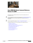
to the PPPoE session, it can be encrypted, filtered, and so forth. Figure 3-1 shows a typical deployment
scenario with a PPPoE client and NAT configured on the Cisco router.
Figure 3-1
PPP over Ethernet with NAT
4
5
2
Internet
3
6
121753
7
1
1
Multiple networked devices—desktops, laptop PCs, switches
2
Fast Ethernet LAN interface (inside interface for NAT)
3
PPPoE client—Cisco 1811 or Cisco 1812 integrated services router
4
Point at which NAT occurs
5
Fast Ethernet WAN interface (outside interface for NAT)
6
Cable modem or other server (for example, a Cisco 6400 server) that is connected to the Internet
7
PPPoE session between the client and a PPPoE server
Cisco 1800 Series Integrated Services Routers (Fixed) Software Configuration Guide
OL-6426-02
3-1
Chapter 3
Configuring PPP over Ethernet with NAT
Configure the Virtual Private Dialup Network Group Number
PPPoE
The PPPoE Client feature on the router provides PPPoE client support on Ethernet interfaces. A dialer
interface must be used for cloning virtual access. Multiple PPPoE client sessions can be configured on
an Ethernet interface, but each session must use a separate dialer interface and a separate dialer pool.
A PPPoE session is initiated on the client side by the Cisco 1800 series router. An established PPPoE
client session can be terminated in one of two ways:
•
By entering the clear vpdn tunnel pppoe command. The PPPoE client session terminates, and the
PPPoE client immediately tries to reestablish the session. This also occurs if the session has a
timeout.
•
By entering the no pppoe-client dial-pool number command to clear the session. The PPPoE client
does not attempt to reestablish the session.
NAT
NAT (represented as the dashed line at the edge of the Cisco router) signifies two addressing domains
and the inside source address. The source list defines how the packet travels through the network.
Configuration Tasks
Perform the following tasks to configure this network scenario:
•
Configure the Virtual Private Dialup Network Group Number
•
Configure the Fast Ethernet WAN Interfaces
•
Configure the Dialer Interface
•
Configure Network Address Translation
An example showing the results of these configuration tasks is shown in the section “Configuration
Example.”
Configure the Virtual Private Dialup Network Group Number
Configuring a virtual private dialup network (VPDN) enables multiple clients to communicate through
the router by way of a single IP address.
Complete the following steps to configure a VPDN, starting from the global configuration mode. See
the “Configure Global Parameters” section on page 1-6 for details about entering this mode.
Step 1
Command or Action
Purpose
vpdn enable
Enables VPDN on the router.
Example:
Router(config)# vpdn enable
Router(config-vpdn)#
Step 2
vpdn group name
Creates and associates a VPDN group with a
customer or VPDN profile.
Example:
Router(config-vpdn)# vpdn group 1
Router(config-vpdn-grp)#
Cisco 1800 Series Integrated Services Routers (Fixed) Software Configuration Guide
3-2
OL-6426-02
Chapter 3
Configuring PPP over Ethernet with NAT
Configure the Fast Ethernet WAN Interfaces
Step 3
Command or Action
Purpose
request-dialin
Creates a request-dialin VPDN subgroup,
indicating the dialing direction, and initiates the
tunnel.
Example:
Router(config-vpdn-grp)# request-dialin
Router(config-vpdn-grp)#
Step 4
initiate to ip ip-address
Specifies the address to which requests are
tunneled.
Example:
For details about this command and additional
parameters that can be set, see the Cisco IOS Dial
Technologies Command Reference.
Router(config-vpdn-grp)# initiate to
192.168.1.1
Router(config-vpdn-grp)#
Step 5
protocol {l2f | l2tp | pppoe | any}
Specifies the type of sessions the VPDN subgroup
can establish.
Example:
Router(config-vpdn-grp)# protocol pppoe
Router(config-vpdn-grp)#
Step 6
exit
Exits VPDN group configuration.
Example:
Router(config-vpdn-grp)# exit
Router(config-vpdn)#
Step 7
exit
Exits VPDN configuration, returning to global
configuration mode.
Example:
Router(config-vpdn)# exit
Router(config)#
Configure the Fast Ethernet WAN Interfaces
In this scenario, the PPPoE client (your Cisco router) communicates over a 10/100-Mbps Ethernet
interface on both the inside and the outside.
Note
The Cisco 1800 series integrated services fixed-configuration routers have a hardware limitation on the
Fast Ethernet ports FE0 and FE1. In half-duplex mode, when traffic reaches or exceeds 100% capacity
(equal to or greater than 5 Mbps in each direction), the interface experiences excessive collisions and
resets every second. To avoid this problem, you must limit the traffic capacity to less than 100%.
Cisco 1800 Series Integrated Services Routers (Fixed) Software Configuration Guide
OL-6426-02
3-3
Chapter 3
Configuring PPP over Ethernet with NAT
Configure the Fast Ethernet WAN Interfaces
Perform these steps to configure the Fast Ethernet WAN interfaces, starting in global configuration
mode:
Step 1
Command
Purpose
interface type number
Enters interface configuration mode for a
Fast Ethernet WAN interface.
Example:
The Cisco 1800 integrated services routers have
two Fast Ethernet WAN interfaces. You can use
these steps to configure one or both of them.
Router(config)#interface fastethernet 0
Router(config-if)#
Step 2
pppoe-client dial-pool-number number
Configures the PPPoE client and specifies the
dialer interface to use for cloning.
Example:
Router(config-if)# pppoe-client
dial-pool-number 1
Router(config-if)#
Step 3
no shutdown
Enables the Fast Ethernet interface and the
configuration changes just made to it.
Example:
Router(config-if)# no shutdown
Router(config-if)#
Step 4
exit
Example:
Exits configuration mode for the Fast Ethernet
interface and returns to global configuration
mode.
Router(config-if)# exit
Router(config)#
Cisco 1800 Series Integrated Services Routers (Fixed) Software Configuration Guide
3-4
OL-6426-02
Chapter 3
Configuring PPP over Ethernet with NAT
Configure the Dialer Interface
Configure the Dialer Interface
The dialer interface indicates how to handle traffic from the clients, including, for example, default
routing information, the encapsulation protocol, and the dialer pool to use. The dialer interface is also
used for cloning virtual access. Multiple PPPoE client sessions can be configured on a Fast Ethernet
interface, but each session must use a separate dialer interface and a separate dialer pool.
Complete the following steps to configure a dialer interface for one of the Fast Ethernet LAN interfaces
on the router, starting in global configuration mode.
Step 1
Command
Purpose
interface dialer dialer-rotary-group-number
Creates a dialer interface (numbered 0–255), and
enters interface configuration mode.
Example:
Router(config)# interface dialer 0
Router(config-if)#
Step 2
ip address negotiated
Specifies that the IP address for the interface is
obtained through PPP/IPCP (IP Control Protocol)
address negotiation.
Example:
Router(config-if)# ip address negotiated
Router(config-if)#
Step 3
ip mtu bytes
Sets the size of the IP maximum transmission unit
(MTU). The default minimum is 128 bytes. The
maximum for Ethernet is 1492 bytes.
Example:
Router(config-if)# ip mtu 1492
Router(config-if)#
Step 4
encapsulation encapsulation-type
Sets the encapsulation type to PPP for the data
packets being transmitted and received.
Example:
Router(config-if)# encapsulation ppp
Router(config-if)#
Step 5
ppp authentication {protocol1 [protocol2...]}
Sets the PPP authentication method to Challenge
Handshake Authentication Protocol (CHAP).
Example:
For details about this command and additional
parameters that can be set, see the Cisco IOS
Security Command Reference.
Router(config-if)# ppp authentication chap
Router(config-if)#
Step 6
dialer pool number
Specifies the dialer pool to use to connect to a
specific destination subnetwork.
Example:
Router(config-if)# dialer pool 1
Router(config-if)#
Cisco 1800 Series Integrated Services Routers (Fixed) Software Configuration Guide
OL-6426-02
3-5
Chapter 3
Configuring PPP over Ethernet with NAT
Configure the Dialer Interface
Step 7
Command
Purpose
dialer-group group-number
Assigns the dialer interface to a dialer group
(1–10).
Example:
Tip
Router(config-if)# dialer group 1
Router(config-if)#
Step 8
exit
Using a dialer group controls access to
your router.
Exits the dialer 0 interface configuration.
Example:
Router(config-if)# exit
Router(config)#
Step 9
dialer-list dialer-group protocol protocol-name
{permit | deny | list access-list-number |
access-group}
Creates a dialer list and associates a dial group
with it. Packets are then forwarded through the
specified interface dialer group.
Example:
For details about this command and additional
parameters that can be set, see the Cisco IOS Dial
Technologies Command Reference.
Router(config)# dialer-list 1 protocol ip
permit
Router(config)#
Step 10
ip route prefix mask {interface-type
interface-number}
Example:
Router(config)# ip route 10.10.25.2
0.255.255.255 dialer 0
Router(config)#
Sets the IP route for the default gateway for the
dialer 0 interface.
For details about this command and additional
parameters that can be set, see the Cisco IOS IP
Command Reference, Volume 2; Routing
Protocols.
Cisco 1800 Series Integrated Services Routers (Fixed) Software Configuration Guide
3-6
OL-6426-02
Chapter 3
Configuring PPP over Ethernet with NAT
Configure Network Address Translation
Configure Network Address Translation
Network Address Translation (NAT) translates packets from addresses that match a standard access list,
using global addresses allocated by the dialer interface. Packets that enter the router through the inside
interface, packets sourced from the router, or both are checked against the access list for possible address
translation. You can configure NAT for either static or dynamic address translations.
Perform these steps to configure the outside Fast Ethernet WAN interface with dynamic NAT, beginning
in global configuration mode:
Step 1
Command
Purpose
ip nat pool name start-ip end-ip {netmask
netmask | prefix-length prefix-length}
Creates pool of global IP addresses for NAT.
Example:
Router(config)# ip nat pool pool1
192.168.1.0 192.168.2.0 netmask 0.0.0.255
Router(config)#
Step 2
ip nat inside source {list access-list-number}
{interface type number | pool name} [overload]
Enables dynamic translation of addresses on the
inside interface.
Example 1:
The first example shows the addresses permitted
by the access list 1 to be translated to one of the
addresses specified in the dialer interface 0.
Router(config)# ip nat inside source list 1
interface dialer 0 overload
The second example shows the addresses
permitted by access list acl1 to be translated to one
of the addresses specified in the NAT pool pool1.
or
Example 2:
Router(config)# ip nat inside source list
acl1 pool pool1
Step 3
interface type number
For details about this command and additional
parameters that can be set, as well as information
about enabling static translation, see the
Cisco IOS IP Command Reference, Volume 1 of 4:
Addressing and Services.
Enters configuration mode for the VLAN (on
which the Fast Ethernet LAN interfaces reside) to
be the inside interface for NAT.
Example:
Router(config)# interface vlan 1
Router(config-if)#
Step 4
ip nat {inside | outside}
Identifies the specified VLAN interface as the
NAT inside interface.
Example:
For details about this command and additional
parameters that can be set, as well as information
about enabling static translation, see the
Cisco IOS IP Command Reference, Volume 1 of 4:
Addressing and Services.
Router(config-if)# ip nat inside
Router(config-if)#
Cisco 1800 Series Integrated Services Routers (Fixed) Software Configuration Guide
OL-6426-02
3-7
Chapter 3
Configuring PPP over Ethernet with NAT
Configure Network Address Translation
Step 5
Command
Purpose
no shutdown
Enables the configuration changes just made to the
Ethernet interface.
Example:
Router(config-if)# no shutdown
Router(config-if)#
Step 6
exit
Exits configuration mode for the Fast Ethernet
interface.
Example:
Router(config-if)# exit
Router(config)#
Step 7
interface type number
Example:
Enters configuration mode for the Fast Ethernet
WAN interface (FE0 or FE1) to be the outside
interface for NAT.
Router(config)#interface fastethernet 0
Router(config-if)#
Step 8
ip nat {inside | outside}
Identifies the specified WAN interface as the NAT
outside interface.
Example:
For details about this command and additional
parameters that can be set, as well as information
about enabling static translation, see the
Cisco IOS IP Command Reference, Volume 1 of 4:
Addressing and Services.
Router(config-if)# ip nat outside
Router(config-if)#
Step 9
no shutdown
Enables the configuration changes just made to the
Ethernet interface.
Example:
Router(config-if)# no shutdown
Router(config-if)#
Step 10
exit
Exits configuration mode for the Fast Ethernet
interface.
Example:
Router(config-if)# exit
Router(config)#
Step 11
access-list access-list-number {deny | permit}
source [source-wildcard]
Example:
Defines a standard access list indicating which
addresses need translation.
Note
All other addresses are implicitly denied.
Router(config)# access-list 1 permit
192.168.1.0 0.0.0.255
Note
If you want to use NAT with a virtual-template interface, you must configure a loopback interface. See
Chapter 1, “Basic Router Configuration,” for information on configuring a loopback interface.
Cisco 1800 Series Integrated Services Routers (Fixed) Software Configuration Guide
3-8
OL-6426-02
Chapter 3
Configuring PPP over Ethernet with NAT
Configuration Example
For complete information on the NAT commands, see the Cisco IOS Release 12.3 documentation set.
For more general information on NAT concepts, see Appendix B, “Concepts.”
Configuration Example
The following configuration example shows a portion of the configuration file for the PPPoE scenario
described in this chapter.
The VLAN interface has an IP address of 192.168.1.1 with a subnet mask of 255.255.255.0. NAT is
configured for inside and outside.
Note
Since the VLAN interface is on LAN, we have used a private IP address.
Note
Commands marked by “(default)” are generated automatically when you run the show running-config
command.
!
vpdn enable
vpdn-group 1
request-dialin
protocol pppoe
!
interface vlan 1
ip address 192.168.1.1 255.255.255.0
no ip directed-broadcast (default)
ip nat inside
!
interface FastEthernet 0
ip address 192.1.12.2 255.255.255.0
no ip directed-broadcast (default)
ip nat outside
!
interface dialer 1
ip address negotiated
ppp authentication chap
dialer pool 1
dialer-group 1
!
dialer-list 1 protocol ip permit
ip nat inside source list 1 interface dialer 0 overload
ip classless (default)
ip route 10.10.25.2 0.255.255.255 dialer 0
!
Cisco 1800 Series Integrated Services Routers (Fixed) Software Configuration Guide
OL-6426-02
3-9
Chapter 3
Configuring PPP over Ethernet with NAT
Configuration Example
Verifying Your Configuration
Use the show ip nat statistics command in privileged EXEC mode to verify NAT configuration. You
should see verification output similar to the following example:
Router# show ip nat statistics
Total active translations: 0 (0 static, 0 dynamic; 0 extended)
Outside interfaces:
FastEthernet4
Inside interfaces:
Vlan1
Hits: 0 Misses: 0
CEF Translated packets: 0, CEF Punted packets: 0
Expired translations: 0
Dynamic mappings:
-- Inside Source
[Id: 1] access-list 1 interface Dialer0 refcount 0
Queued Packets: 0
Cisco 1800 Series Integrated Services Routers (Fixed) Software Configuration Guide
3-10
OL-6426-02
4
C H A P T E R
Configuring PPP over ATM with NAT
The Cisco 1801, Cisco 1802, and Cisco 1803 access routers support Point-to-Point Protocol over
Asynchronous Transfer Mode (PPPoA) clients and network address translation (NAT).
Multiple PCs can be connected to the LAN behind the router. Before traffic from the PCs is sent to the
PPPoA session, it can be encrypted, filtered, and so forth. PPP over ATM provides a network solution
with simplified address handling and straight user verification like a dial network. Figure 4-1 shows a
typical deployment scenario with a PPPoA client and NAT configured on the Cisco router. This scenario
uses a single static IP address for the ATM connection.
Figure 4-1
PPP over ATM with NAT
4
5
2
ISP
3
6
92340
4
1
2
2
3
Small business with multiple networked devices—desktops, laptop PCs, switches
3
Fast Ethernet LAN interface (inside interface
for NAT, 192.168.1.1/24)6
4
PPPoA Client—Cisco 1801, Cisco 1802, or Cisco 1803 router
7
Point at which NAT occurs
5
ATM WAN interface (outside interface for NAT)
6
PPPoA session between the client and a PPPoA server at the ISP
121753
1
5
1
Cisco 1800 Series Integrated Services Routers (Fixed) Software Configuration Guide
OL-6426-02
4-1
Chapter 4
Configuring PPP over ATM with NAT
In this scenario, the small business or remote user on the Fast Ethernet LAN can connect to an Internet
Service Provider (ISP) using the following protocols on the WAN connection:
•
Asymmetric digital subscriber line (ADSL) over plain old telephone service (POTS) using the
Cisco 1801 router
•
ADSL over integrated services digital network (ISDN) using the Cisco 1802 router
•
Single-pair high-speed digital subscriber line (G.SHDSL) using the Cisco 1803 router
The Fast Ethernet interface carries the data packet through the LAN and off-loads it to the PPP
connection on the ATM interface. The ATM traffic is encapsulated and sent over the ADSL, ISDN, or
G.SHDSL lines. The dialer interface is used to connect to the ISP.
PPPoA
The PPPoA Client feature on the router provides PPPoA client support on ATM interfaces. A dialer
interface must be used for cloning virtual access. Multiple PPPoA client sessions can be configured on
an ATM interface, but each session must use a separate dialer interface and a separate dialer pool.
A PPPoA session is initiated on the client side by the Cisco 1800 series router.
NAT
NAT (represented as the dashed line at the edge of the Cisco router) signifies two addressing domains
and the inside source address. The source list defines how the packet travels through the network.
Configuration Tasks
Perform the following tasks to configure this network scenario:
•
Configure the Dialer Interface
•
Configure the ATM WAN Interface
•
Configure DSL Signaling Protocol
•
Configure Network Address Translation
An example showing the results of these configuration tasks is shown in the section “Configuration
Example.”
Cisco 1800 Series Integrated Services Routers (Fixed) Software Configuration Guide
4-2
OL-6426-02
Chapter 4
Configuring PPP over ATM with NAT
Configure the Dialer Interface
Configure the Dialer Interface
The dialer interface indicates how to handle traffic from the clients, including, for example, default
routing information, the encapsulation protocol, and the dialer pool to use. It is also used for cloning
virtual access. Multiple PPPoA client sessions can be configured on an ATM interface, but each session
must use a separate dialer interface and a separate dialer pool.
Perform these steps to configure a dialer interface for the ATM interface on the router, starting in global
configuration mode.
Step 1
Command
Purpose
interface dialer dialer-rotary-group-number
Creates a dialer interface (numbered 0–255), and
enters into interface configuration mode.
Example:
Router(config)# interface dialer 0
Router(config-if)#
Step 2
ip address negotiated
Specifies that the IP address for the dialer
interface is obtained through PPP/IPCP (IP
Control Protocol) address negotiation.
Example:
Router(config-if)# ip address negotiated
Router(config-if)#
Step 3
ip mtu bytes
Sets the size of the IP maximum transmission unit
(MTU). The default minimum is 128 bytes. The
maximum for ATM is 4470 bytes.
Example:
Router(config-if)# ip mtu 4470
Router(config-if)#
Step 4
encapsulation encapsulation-type
Sets the encapsulation type to PPP for the data
packets being transmitted and received.
Example:
Router(config-if)# encapsulation ppp
Router(config-if)#
Step 5
ppp authentication {protocol1 [protocol2...]}
Sets the PPP authentication method.
Example:
The example applies the Challenge Handshake
Authentication Protocol (CHAP).
Router(config-if)# ppp authentication chap
Router(config-if)#
Step 6
dialer pool number
For details about this command and additional
parameters that can be set, see the Cisco IOS
Security Command Reference.
Specifies the dialer pool to use to connect to a
specific destination subnetwork.
Example:
Router(config-if)# dialer pool 1
Router(config-if)#
Cisco 1800 Series Integrated Services Routers (Fixed) Software Configuration Guide
OL-6426-02
4-3
Chapter 4
Configuring PPP over ATM with NAT
Configure the Dialer Interface
Step 7
Command
Purpose
dialer-group group-number
Assigns the dialer interface to a dialer group
(1–10).
Example:
Tip
Router(config-if)# dialer-group 1
Router(config-if)#
Step 8
exit
Using a dialer group controls access to
your router.
Exits the dialer 0 interface configuration.
Example:
Router(config-if)# exit
Router(config)#
Step 9
dialer-list dialer-group protocol protocol-name
{permit | deny | list access-list-number |
access-group}
Creates a dialer list and associates a dial group
with it. Packets are then forwarded through the
specified interface dialer group.
Example:
For details about this command and additional
parameters that can be set, see the Cisco IOS Dial
Technologies Command Reference.
Router(config)# dialer-list 1 protocol ip
permit
Router(config)#
Step 10
ip route prefix mask {interface-type
interface-number}
Example:
Router(config)# ip route 10.10.25.0
255.255.255.0 dialer 0
Router(config)#
Sets the IP route for the default gateway for the
dialer 0 interface.
For details about this command and additional
parameters that can be set, see the Cisco IOS IP
Command Reference, Volume 1 of 4: Routing
Protocols.
Repeat these steps for any additional dialer interfaces or dialer pools needed.
Cisco 1800 Series Integrated Services Routers (Fixed) Software Configuration Guide
4-4
OL-6426-02
Chapter 4
Configuring PPP over ATM with NAT
Configure the ATM WAN Interface
Configure the ATM WAN Interface
Perform these steps to configure the ATM interface, beginning in global configuration mode.
Step 1
Command
Purpose
interface type number
Enters interface configuration mode for the ATM
interface (labeled ADSLoPOTS or G.SHDSL on
the back of your router).
Example:
Step 2
Router(config)# interface atm 0
Router(config-if)#
Note
pvc vpi/vci
Creates an ATM PVC for each end node (up to ten)
with which the router communicates. Enters ATM
virtual circuit configuration mode.
Example:
Router(config-if)# pvc 8/35
Router(config-if-atm-vc)#
This interface was initially configured
during basic router configuration. See
“Configure WAN Interfaces” section on
page 1-7.
When a PVC is defined, AAL5SNAP
encapsulation is defined by default. Use the
encapsulation command to change this, as shown
in Step 3. The VPI and VCI arguments cannot be
simultaneously specified as zero; if one is 0, the
other cannot be 0.
For details about this command and additional
parameters that can be set, see the Cisco IOS
Wide-Area Networking Command Reference.
Step 3
encapsulation {aal5auto | aal5autoppp
virtual-template number [group group-name] |
aal5ciscoppp virtual-template number |
aal5mux protocol | aal5nlpid | aal5snap}
Example:
Specifies the encapsulation type for the PVC and
points back to the dialer interface.
For details about this command and additional
parameters that can be set, see the Cisco IOS
Wide-Area Networking Command Reference.
Router(config-if-atm-vc)# encapsulation
aal5mux ppp dialer
Router(config-if-atm-vc)#
Step 4
dialer pool-member number
Example:
Specifies the ATM interface as a member of a
dialer profile dialing pool. The pool number must
be in the range of 1–255.
Router(config-if-atm-vc)# dialer
pool-member 1
Router(config-if-atm-vc)#
Cisco 1800 Series Integrated Services Routers (Fixed) Software Configuration Guide
OL-6426-02
4-5
Chapter 4
Configuring PPP over ATM with NAT
Configure DSL Signaling Protocol
Step 5
Command
Purpose
no shutdown
Enables interface and configuration changes just
made to the ATM interface.
Example:
Router(config-if-atm-vc)# no shutdown
Router(config-if)#
Step 6
exit
Exits configuration mode for the ATM interface.
Example:
Router(config-if)# exit
Router(config)#
Configure DSL Signaling Protocol
DSL signaling must be configured on the ATM interface for connection to your ISP. The Cisco 1801
supports ADSL signaling over POTS, the Cisco 1802 supports ADSL signaling over ISDN, and the
Cisco 1803 supports SHDSL signaling.
Based on the router you are configuring, see one of the following sections to configure the appropriate
DSL signaling protocol.
•
Configuring ADSL
•
Configuring SHDSL
Configuring ADSL
The default configuration for ADSL signaling is shown in Table 4-1.
Table 4-1
Default ADSL Configuration
Attribute
Description
Default Value
Operating mode
Specifies the operating mode of the digital
subscriber line (DSL) for an ATM interface.
Auto
•
ADSL over POTS—ANSI or ITU full
rate, or automatic selection.
•
ADSL over ISDN—ITU full rate, ETSI,
or automatic selection.
Loss of margin
Specifies the number of times a loss of margin
may occur.
Training log
Toggles between enabling the training log and Disabled
disabling the training log.
Cisco 1800 Series Integrated Services Routers (Fixed) Software Configuration Guide
4-6
OL-6426-02
Chapter 4
Configuring PPP over ATM with NAT
Configure DSL Signaling Protocol
If you wish to change any of these settings, use one of the following commands in global configuration
mode.
•
dsl operating-mode (from the ATM interface configuration mode)
•
dsl lom integer
•
dsl enable-training-log
See the Cisco IOS Wide-Area Networking Command Reference for details of these commands.
Verify the Configuration
You can verify that the configuration is set the way you want using the show dsl interface atm 0
command from privileged EXEC mode.
Configuring SHDSL
Complete the following steps to configure the DSL controller in your router to use SHDSL signaling,
beginning in global configuration mode.
Step 1
Command
Purpose
controller dsl port
Enters the configuration mode for the DSL
controller.
Example:
Router(config)# controller dsl 0
Router(config-controller)#
Step 2
line-term {co | cpe}
Specifies if the DSL line is terminated at a central
office (CO) or at customer premises equipment
(CPE).
Example:
Router(config-controller)# line-term co
Router(config-controller)#
Step 3
exit
Exits controller configuration mode, returning to
global configuration mode.
Example:
Router(config-controller)# exit
Router(config)#
Step 4
mode protocol
Specifies the mode of the DSL controller and
enters controller configuration mode.
Example:
Router(config)# mode atm
Router(config-controller)#
Cisco 1800 Series Integrated Services Routers (Fixed) Software Configuration Guide
OL-6426-02
4-7
Chapter 4
Configuring PPP over ATM with NAT
Configure DSL Signaling Protocol
Command
Step 5
line-mode {4-wire enhanced | 4-wire standard | Specifies whether this DSL connection is
2-wire}
operating in 2-wire, 4-wire standard, or 4-wire
enhanced mode.
Example:
Router(config-controller)# line-mode 4-wire
standard
Router(config-controller)#
Step 6
Purpose
ignore-error-duration number
Note
line mode 4-wire will default to 4-wire
enhanced mode.
Specifies how long, 15 to 30 seconds, to ignore
errors.
Example:
Router(config-controller)#
ignore-error-duration 15
Router(config-controller)#
Step 7
exit
Exits controller configuration mode, returning to
global configuration mode.
Example:
Router(config-controller)# exit
Router(config)#
Note
If you are integrating your Cisco router into a European network, please use one of the following
commands:
For CO mode, use the dsl dsl-mode shdsl symmetric annex {A | B | B-ANFP} command to choose
annex B or B-ANFP.
For CPE mode, use the dsl dsl-mode shdsl symmetric annex {A | A-B | A-B-ANFP | B | B-ANFP} to
choose any option except option A.
The router uses annex A by default (United States).
Verify the Configuration
You can verify that the configuration is set the way you want using the show controllers dsl command
from privileged EXEC mode.
Router# show controllers dsl 0
DSL 0 controller UP
SLOT 0: Globespan xDSL controller chipset
Line Mode: Four Wire Standard Mode
DSL mode: SHDSL Annex A
Frame mode: Utopia
Configured Line rate: Auto
Line Re-activated 6 times after system bootup
LOSW Defect alarm: ACTIVE
CRC per second alarm: ACTIVE
Line termination: CPE
Current 15 min CRC: 0
Current 15 min LOSW Defect: 0
Cisco 1800 Series Integrated Services Routers (Fixed) Software Configuration Guide
4-8
OL-6426-02
Chapter 4
Configuring PPP over ATM with NAT
Configure Network Address Translation
Current 15 min ES Defect: 0
Current 15 min SES Defect: 0
Current 15 min UAS Defect: 33287
Previous
Previous
Previous
Previous
Previous
15
15
15
15
15
min
min
min
min
min
CRC Defect: 0
LOSW Defect: 0
ES Defect: 0
SES Defect: 0
UAS Defect: 0
Line-0 status
Chipset Version: 0
Firmware Version: A388
Modem Status: Data, Status 1
Last Fail Mode: No Failure status:0x0
Line rate: 2312 Kbps
Framer Sync Status: In Sync
Rcv Clock Status: In the Range
Loop Attenuation: 341.1450 dB
Transmit Power: 7.5 dB
Receiver Gain: 22.5420 dB
SNR Sampling: 36.8590 dB
Dying Gasp: Present
Configure Network Address Translation
Network Address Translation (NAT) translates packets from addresses that match a standard access list,
using global addresses allocated by the dialer interface. Packets that enter the router through the inside
interface, packets sourced from the router, or both are checked against the access list for possible address
translation. You can configure NAT for either static or dynamic address translations.
Perform these steps to configure the outside ATM WAN interface with dynamic NAT, beginning in global
configuration mode:
Cisco 1800 Series Integrated Services Routers (Fixed) Software Configuration Guide
OL-6426-02
4-9
Chapter 4
Configuring PPP over ATM with NAT
Configure Network Address Translation
Step 1
Command
Purpose
ip nat pool name start-ip end-ip {netmask
netmask | prefix-length prefix-length}
Creates pool of global IP addresses for NAT.
Example:
Router(config)# ip nat pool pool1
192.168.1.0 192.168.2.0 netmask 0.0.0.255
Router(config)#
Step 2
ip nat inside source {list access-list-number}
{interface type number | pool name} [overload]
Enables dynamic translation of addresses on the
inside interface.
Example 1:
The first example shows the addresses permitted
by the access list 1 to be translated to one of the
addresses specified in the dialer interface 0.
Router(config)# ip nat inside source list 1
interface dialer 0 overload
or
Example 2:
Router(config)# ip nat inside source list
acl1 pool pool1
Step 3
interface type number
Example:
Router(config)# interface vlan 1
Router(config-if)#
Step 4
For details about this command and additional
parameters that can be set, as well as information
about enabling static translation, see the Cisco
IOS IP Command Reference, Volume 1 of 4:
Addressing and Services.
Enters configuration mode for the VLAN (on
which the Fast Ethernet LAN interfaces
[FE2–FE9] reside) to be the inside interface
for NAT.
ip nat {inside | outside}
Applies NAT to the Fast Ethernet LAN interface
as the inside interface.
Example:
For details about this command and additional
parameters that can be set, as well as information
about enabling static translation, see the Cisco
IOS IP Command Reference, Volume 1 of 4:
Addressing and Services.
Router(config-if)# ip nat inside
Router(config-if)#
Step 5
The second example shows the addresses
permitted by access list acl1 to be translated to one
of the addresses specified in the NAT pool pool1.
no shutdown
Enables the configuration changes just made to the
Ethernet interface.
Example:
Router(config-if)# no shutdown
Router(config-if)#
Step 6
exit
Exits configuration mode for the Fast Ethernet
interface.
Example:
Router(config-if)# exit
Router(config)#
Cisco 1800 Series Integrated Services Routers (Fixed) Software Configuration Guide
4-10
OL-6426-02
Chapter 4
Configuring PPP over ATM with NAT
Configuration Example
Step 7
Command
Purpose
interface type number
Enters configuration mode for the ATM WAN
interface (FE0 or FE1) to be the outside interface
for NAT.
Example:
Router(config)#interface fastethernet 0
Router(config-if)#
Step 8
ip nat {inside | outside}
Identifies the specified WAN interface as the NAT
outside interface.
Example:
For details about this command and additional
parameters that can be set, as well as enabling
static translation, see the Cisco IOS IP Command
Reference, Volume 1 of 4: Addressing and
Services.
Router(config-if)# ip nat outside
Router(config-if)#
Step 9
no shutdown
Enables the configuration changes just made to the
Ethernet interface.
Example:
Router(config-if)# no shutdown
Router(config-if)#
Step 10
exit
Exits configuration mode for the ATM interface.
Example:
Router(config-if)# exit
Router(config)#
Step 11
access-list access-list-number {deny | permit}
source [source-wildcard]
Defines a standard access list permitting addresses
that need translation.
Note
Example:
All other addresses are implicitly denied.
Router(config)# access-list 1 permit
192.168.1.0 0.0.0.255
Note
If you want to use NAT with a virtual-template interface, you must configure a loopback interface. See
Chapter 1, “Basic Router Configuration,” for information on configuring the loopback interface.
For complete information on NAT commands, see the Cisco IOS Release 12.3 documentation set. For
more general information on NAT concepts, see Appendix B, “Concepts.”
Configuration Example
The following configuration example shows a portion of the configuration file for a client in the PPPoA
scenario described in this chapter.
The VLAN interface has an IP address of 192.168.1.1 with a subnet mask of 255.255.255.0. NAT is
configured for inside and outside.
Cisco 1800 Series Integrated Services Routers (Fixed) Software Configuration Guide
OL-6426-02
4-11
Chapter 4
Configuring PPP over ATM with NAT
Configuration Example
Note
Commands marked by “(default)” are generated automatically when you run the show running-config
command.
!
interface Vlan1
ip address 192.168.1.1 255.255.255.0
ip nat inside
ip virtual-reassembly (default)
!
interface ATM0
no ip address
ip nat outside
ip virtual-reassembly
no atm ilmi-keepalive
pvc 8/35
encapsulation aal5mux ppp dialer
dialer pool-member 1
!
dsl operating-mode auto
!
interface Dialer0
ip address negotiated
ip mtu 1492
encapsulation ppp
dialer pool 1
dialer-group 1
ppp authentication chap
!
ip classless (default)
!
ip nat pool pool1 192.168.1.0 192.168.2.0 netmask 0.0.0.255
ip nat inside source list 1 interface Dialer0 overload
!
access-list 1 permit 192.168.1.0 0.0.0.255
dialer-list 1 protocol ip permit
ip route 10.10.25.2 0.255.255.255 dialer 0
!
Verifying Your Configuration
Use the show ip nat statistics command in privileged EXEC mode to verify the PPPoA client with NAT
configuration. You should see verification output similar to the following example:
Router# show ip nat statistics
Total active translations: 0 (0 static, 0 dynamic; 0 extended)
Outside interfaces:
ATM0
Inside interfaces:
Vlan1
Hits: 0 Misses: 0
CEF Translated packets: 0, CEF Punted packets: 0
Expired translations: 0
Dynamic mappings:
-- Inside Source
[Id: 1] access-list 1 interface Dialer0 refcount 0
Queued Packets: 0
Cisco 1800 Series Integrated Services Routers (Fixed) Software Configuration Guide
4-12
OL-6426-02
CH A P T E R
5
Configuring a LAN with DHCP and VLANs
The Cisco 1800 series integrated services fixed-configuration routers support clients on both physical
LANs and virtual LANs (VLANs). The routers can use the Dynamic Host Configuration Protocol
(DHCP) to enable automatic assignment of IP configurations for nodes on these networks. Other
interfaces and configurations of the VLANs are described in the “Switch Port Configurations” section
on page 5-7.
1
Fast Ethernet LAN (with multiple networked devices)
2
Router and DHCP server—Cisco 1800 series integrated services router—connected to the Internet
3
VLAN 1
4
VLAN 2
DHCP
DHCP, which is described in RFC 2131, uses a client/server model for address allocation. As an
administrator, you can configure your Cisco 1800 integrated services fixed-configuration router to act as
a DHCP server, providing IP address assignment and other TCP/IP-oriented configuration information
to your workstations. DHCP frees you from having to manually assign an IP address to each client.
When you configure a DHCP server, you must configure the server properties, policies, and DHCP
options.
Note
Whenever you change server properties, you must reload the server with the configuration data from the
Network Registrar database.
VLANs
The Cisco 1800 series integrated services routers (fixed) support eight Fast Ethernet ports on which you
can configure VLANs. See the “Switch Port Configurations” section on page 5-7 for a description of the
interfaces and features that can be configured on the switch ports and a link to a document containing
the configuration procedures.
VLANs enable networks to be segmented and formed into logical groups of users, regardless of the
user’s physical location or LAN connection.
Configuration Tasks
Perform the following tasks to configure this network scenario:
•
OL-6426-03
Configure DHCP
5-1
Chapter 5
Configuring a LAN with DHCP and VLANs
Configure DHCP
•
Note
Configure VLANs
The procedures in this chapter assume you have already configured basic router features as well as
PPPoE or PPPoA with NAT. If you have not performed these configurations tasks, see Chapter 1, “Basic
Router Configuration,” Chapter 3, “Configuring PPP over Ethernet with NAT,” and Chapter 4,
“Configuring PPP over ATM with NAT” as appropriate for your router. See the Cisco IOS IP
Configuration Guide to assign an IP address to the ports.
Configure DHCP
Perform these steps to configure your router for DHCP operation, beginning in global configuration
mode:
Step 1
Command
Purpose
ip domain name name
Identifies the default domain that the router uses to
complete unqualified hostnames (names without a
dotted-decimal domain name).
Example:
Router(config)# ip domain name smallbiz.com
Router(config)#
Step 2
ip name-server server-address1
[server-address2...server-address6]
Specifies the address of one or more Domain
Name System (DNS) servers to use for name and
address resolution.
Example:
Router(config)# ip name-server 192.168.11.12
Router(config)#
Step 3
ip dhcp excluded-address low-address
[high-address]
Specifies IP addresses that the DHCP server
should not assign to DHCP clients. In this
example, we are excluding the router address.
Example:
Router(config)# ip dhcp excluded-address
192.168.9.0
Step 4
ip dhcp pool name
Example:
Creates a DHCP address pool on the router and
enters DHCP pool configuration mode. The name
argument can be a string or an integer.
Router(config)# ip dhcp pool dpool1
Router(config-dhcp)#
Step 5
network network-number [mask | prefix-length]
Defines subnet number (IP) address for the DHCP
address pool, optionally including the mask.
Example:
Router(config-dhcp)# network 10.10.0.0
255.255.255.0
Router(config-dhcp)#
Cisco 1800 Series Integrated Services Routers (Fixed) Software Configuration Guide
5-2
OL-6426-03
Chapter 5
Configuring a LAN with DHCP and VLANs
Configure DHCP
Step 6
Command
Purpose
import all
Imports DHCP option parameters into the DHCP
portion of the router database.
Example:
Router(config-dhcp)# import all
Router(config-dhcp)#
Step 7
default-router address [address2...address8]
Specifies up to 8 default routers for a DHCP client.
Example:
Router(config-dhcp)# default-router 10.1.1.1
Router(config-dhcp)#
Step 8
dns-server address [address2...address8]
Specifies up to 8 DNS servers available to a DHCP
client.
Example:
Router(config-dhcp)# dns-server 192.168.35.2
Router(config-dhcp)#
Step 9
domain-name domain
Specifies the domain name for a DHCP client.
Example:
Router(config-dhcp)# domain-name cisco.com
Router(config-dhcp)#
Step 10
exit
Exits DHCP configuration mode, and enters
global configuration mode.
Example:
Router(config-dhcp)# exit
Router(config)#
Configuration Example
The following configuration example shows a portion of the configuration file for the DCHP
configuration described in this chapter.
ip dhcp excluded-address 192.168.9.0
!
ip dhcp pool dpool1
import all
network 10.10.0.0 255.255.255.0
default-router 10.10.10.10
dns-server 192.168.35.2
domain-name cisco.com
!
ip domain name smallbiz.com
ip name-server 192.168.11.12
Cisco 1800 Series Integrated Services Routers (Fixed) Software Configuration Guide
OL-6426-03
5-3
Chapter 5
Configuring a LAN with DHCP and VLANs
Configure DHCP
Verify Your DHCP Configuration
Use the following commands to view your DHCP configuration.
•
show ip dhcp import—Displays the optional parameters imported into the DHCP server database.
•
show ip dhcp pool—Displays information about the DHCP address pools.
•
show ip dhcp server statistics—Displays the DHCP server statistics, such as the number of address
pools, bindings, and so forth.
Router# show ip dhcp import
Address Pool Name: dpool1
Router# show ip dhcp pool
Pool dpool1 :
Utilization mark (high/low)
: 100 / 0
Subnet size (first/next)
: 0 / 0
Total addresses
: 254
Leased addresses
: 0
Pending event
: none
1 subnet is currently in the pool :
Current index
IP address range
10.10.0.1
10.10.0.1
- 10.10.0.254
Router# show ip dhcp
Memory usage
Address pools
Database agents
Automatic bindings
Manual bindings
Expired bindings
Malformed messages
Secure arp entries
server statistics
15419
1
0
0
0
0
0
0
Message
BOOTREQUEST
DHCPDISCOVER
DHCPREQUEST
DHCPDECLINE
DHCPRELEASE
DHCPINFORM
Received
0
0
0
0
0
0
Message
BOOTREPLY
DHCPOFFER
DHCPACK
DHCPNAK
Router#
Sent
0
0
0
0
Leased addresses
0
Cisco 1800 Series Integrated Services Routers (Fixed) Software Configuration Guide
5-4
OL-6426-03
Chapter 5
Configuring a LAN with DHCP and VLANs
Configure VLANs
Configure VLANs
Perform these steps to configure VLANs on your router, beginning in global configuration mode:
Step 1
Command
Purpose
vlan ?
Enters VLAN configuration mode.
Example:
Router# config t
Router(config)#vlan ?
WORD
accounting
ifdescr
ISL VLAN IDs 1-4094
VLAN accounting configuration
VLAN subinterface ifDescr
Router(config)#vlan
Step 2
ISL VLAN ID
Example:
Router(config)#vlan 2
Router(config-vlan)#
Step 3
exit
Example:
Adds VLANs, with identifiers ranging from
1- 4094.
For details about this command and additional
parameters that can be set, see the Cisco IOS
Switching Services Command Reference.
Updates the VLAN database, propagates it throughout
the administrative domain, and returns to global
configuration mode.
Router(config-vlan)#exit
Router(config)#
Verify Your VLAN Configuration
Use the following commands to view your VLAN configuration.
•
show—Entered from VLAN database mode. Displays summary configuration information for all
configured VLANs.
•
show vlan-switch—Entered from privileged EXEC mode. Displays detailed configuration
information for all configured VLANs.
Router# vlan database
Router(vlan)# show
VLAN ISL Id: 1
Name: default
Media Type: Ethernet
VLAN 802.10 Id: 100001
State: Operational
MTU: 1500
Translational Bridged VLAN: 1002
Translational Bridged VLAN: 1003
VLAN ISL Id: 1002
Name: fddi-default
Media Type: FDDI
VLAN 802.10 Id: 101002
State: Operational
MTU: 1500
Bridge Type: SRB
Cisco 1800 Series Integrated Services Routers (Fixed) Software Configuration Guide
OL-6426-03
5-5
Chapter 5
Configuring a LAN with DHCP and VLANs
Configure VLANs
Translational Bridged VLAN: 1
Translational Bridged VLAN: 1003
VLAN ISL Id: 1003
Name: token-ring-default
Media Type: Token Ring
VLAN 802.10 Id: 101003
State: Operational
MTU: 1500
Bridge Type: SRB
Ring Number: 0
Bridge Number: 1
Parent VLAN: 1005
Maximum ARE Hop Count: 7
Maximum STE Hop Count: 7
Backup CRF Mode: Disabled
Translational Bridged VLAN: 1
Translational Bridged VLAN: 1002
VLAN ISL Id: 1004
Name: fddinet-default
Media Type: FDDI Net
VLAN 802.10 Id: 101004
State: Operational
MTU: 1500
Bridge Type: SRB
Bridge Number: 1
STP Type: IBM
VLAN ISL Id: 1005
Name: trnet-default
Media Type: Token Ring Net
VLAN 802.10 Id: 101005
State: Operational
MTU: 1500
Bridge Type: SRB
Bridge Number: 1
STP Type: IBM
Router# show vlan-switch
VLAN
---1
1002
1003
1004
1005
Name
-------------------------------default
fddi-default
token-ring-default
fddinet-default
trnet-default
VLAN Type
---- ----1
enet
1002 fddi
1003 tr
1004 fdnet
1005 trnet
Router#
SAID
---------100001
101002
101003
101004
101005
MTU
----1500
1500
1500
1500
1500
Parent
-----1005
-
Status
Ports
--------- ------------------------------active
Fa0, Fa1, Fa2, Fa3
active
active
active
active
RingNo
-----0
-
BridgeNo
-------1
1
Stp
---ibm
ibm
BrdgMode
-------srb
-
Trans1
-----1002
1
1
0
0
Trans2
-----1003
1003
1002
0
0
Cisco 1800 Series Integrated Services Routers (Fixed) Software Configuration Guide
5-6
OL-6426-03
Chapter 5
Configuring a LAN with DHCP and VLANs
Switch Port Configurations
Switch Port Configurations
The 8 high speed Ethernet ports on the Cisco 1800 (fixed) integrated router supports 8 VLANs per port.
To configure and verify VLANs on the switch ports see the the “Configure VLANs” section on page 5-5
and the “Verify Your VLAN Configuration” section on page 5-5.
Figure 5-1
VLAN Configuration on the Cisco 1800 (Fixed) Router Showing Three VLAN
Segments
Engineering VLAN
IP phones
IP
IP
VLAN
VLAN11
IP
Voice
VLAN
VLAN 2
Switching
router
IP
VLAN33
VLAN
IP
Accounting VLAN
230551
IP
Other procedures for configuring the switch ports, including configuration examples and information on
the features and interfaces are in the Cisco HWIC-4ESW and HWIC-9ESW EtherSwitch Interface Cards
document on Cisco.com. See this document to configure the switch ports. The configuration procedures
described in this document are listed below.
Cisco 1800 Series Integrated Services Routers (Fixed) Software Configuration Guide
OL-6426-03
5-7
Chapter 5
Configuring a LAN with DHCP and VLANs
Switch Port Configurations
•
Configuring VLANs (required)
•
Configuring VLAN Trunking Protocol (optional)
•
Configuring 802.1x Authentication (required)
•
Configuring Spanning Tree on a VLAN (required)
•
Configuring Layer 2 Interfaces (required)
•
Configuring MAC Table Manipulation (required)
•
Configuring the Switched Port Analyzer (required)
•
Configuring Power Management on the Interfaces (optional)
•
IP Multicast Layer 3 Switching (required)
•
Configuring Per-Port Storm Control (optional)
•
Configuring Fallback Bridging (optional)
•
Configuring Separate Voice and Data Submits (optional)
•
Configuring IGMP Snooping (optional)
This section briefly describes the features and interfaces that can be configured on the VLANs assigned
to the switch ports and any differences between the configurations for the HWIC-4ESW and
HWIC-9ESW and the configuration of the switch ports.
VLAN Trunking Protocol (VTP)
VLAN Trunking Protocol(VTP) supports three types of VTP modes – server, client and transparent
modes. In VTP server mode, you create, modify and delete VLANs and specify other configuration
parameters such as the VTP version for the entire VTP domain. VTP clients behave the same way as
VTP servers, but you cannot create, change or delete VLANs on a VTP client. A VTP transparent switch
does not advertise its’ VLAN configuration, and does not synchronize its VLAN configuration based on
received advertisements.
802.1x Authentication
The switch port determines whether a client is granted access to the network. In the default setting, the
port is in the unauthorized state. While in this state, the port disallows all ingress and egress traffic except
for 802.1x packets. When a client has successfully authenticated, the port changes to the authorized
state, allowing all traffic for the client to flow normally.
If a client that does not support 802.1x is connected to an unauthorized 802.1x port, the switch requests
the client’s identity. In this situation, the client does not respond to the request, the port remains in the
unauthorized state, and the client is not granted access to the network.
The 802.1x protocol supports authentication and full authentication, authorization, and accounting
[AAA] and RADIUS modes with port VLAN ID (PVID) and voice VLAN ID (VVID); and with VLAN
assignment with guest VLAN single and multi-host support on the Cisco 1800 (fixed) Configuration
Series.
Note
These security features are not supported on the switch ports: Security Access Control Lists, IP Access
Control Lists (IP- ACLs) for Layer 2 ports, and VLAN ACLs Virtual ACLs.
Cisco 1800 Series Integrated Services Routers (Fixed) Software Configuration Guide
5-8
OL-6426-03
Chapter 5
Configuring a LAN with DHCP and VLANs
Switch Port Configurations
Layer 2 Interfaces
The integrated switch ports support Layer 2 switching across Ethernet ports based on Cisco IOS Catalyst
Software. They support simultaneous, parallel connections between Layer 2 Ethernet segments.
Switched connections between Ethernet segments last only for the duration of the packet. Different
connections can be made for different segments for the next packet. You can configure a range of Layer
2 interfaces, define a range macro, set the interface speed, set the duplex mode, and add a description for
the interface.
MAC Table Manipulation
The MAC table is configured to provide port security. The switch ports use the MAC address tables to
forward traffic between the ports. All MAC addresses in the address table are associated with one or
more ports. The MAC tables include the following types of addresses:
•
Dynamic address–the source MAC address that the switch learns and then drops when not in use.
•
Secure address–manually entered unicast address that is usually associated with a secured port.
Secure addresses do not age.
•
Static address–manually entered unicast or multicast address that does not age and that is not lost
when the switch resets.
The Cisco 1800 (Fixed) Configuration Series supports 100 secure and static MAC addresses. General
MAC addresses are supported for 50 users.
Maximum Switched Virtual Interfaces (SVIs)
A switch virtual interface (SVI) represents a VLAN of switch ports as one interface to the routing or
bridging function in the router. Only one SVI can be associated with a VLAN; it is necessary to configure
an SVI for a VLAN only when you wish to route between VLANs, when you wish to configure
fallback-bridge nonroutable protocols between VLANs, or when you wish to provide IP host
connectivity. Eight SVI interfaces are supported on each port of the fixed router
Switched Port Analyzer (SPAN)
You can configure SPAN sessions using parameters that specify the type of network traffic to monitor.
SPAN sessions allow you to monitor traffic in one or more interfaces and allow you to send ingress
traffic, egress traffic or both to one destination interface.
You can enable spanning tree on a per-VLAN basis and configure various spanning tree features. All
frames have 802.1q tags.
IP Multicast Switching
Multicast switching is Layer 3 switching. To configure Multicast switching, the maximum number of
configured VLANs must be less than or equal to 242. The maximum number of multicast groups is equal
to to the maximum number of VLANs.
You can configure your router to enable multi-cast switching globally, enable IP Protocol Independent
Multicast (PIM) on a Layer 3 interface, and verify the Multicast Layer 3 switching information.
Cisco 1800 Series Integrated Services Routers (Fixed) Software Configuration Guide
OL-6426-03
5-9
Chapter 5
Configuring a LAN with DHCP and VLANs
Switch Port Configurations
Note
Per-Port enabling and disabling of unknown multicast and unicast packets is not supported on the Cisco
1800 (Fixed) configuration router.
Per-Port Storm Control
You can use these per-port storm control techniques to block the forwarding of unnecessary, flooded
traffic.
Fallback Bridging
With Fallback Bridging, the switch bridges together two or more VLANs or routed ports, essentially
connecting multiple VLANs within one bridge domain.
To configure Fallback Bridging for a set of SVIs, the SVIs must be assigned to bridge groups. All bridges
in the same group belong to the same bridge domain. Each SVI can be assigned to only one bridge group.
Separate Voice and Data Subnets
For ease of network administration and increased scalability, network managers can configure the switch
ports to support Cisco IP phones such that the voice and data traffic reside on separate subnets.
IGMP Snooping
By default, IGMP Snooping is globally enabled on the switch ports. When globally enabled or disabled,
it is also enabled or disabled on all VLAN interfaces. It can be enabled and disabled on a per-VLAN
basis.
Note
All of the procedures for configuring the switch ports, including configuration examples and information
on the features and interfaces are in the Cisco HWIC-4ESW and HWIC-9ESW EtherSwitch Interface
Cards document on Cisco.com. See this document to configure the switch ports.
Cisco 1800 Series Integrated Services Routers (Fixed) Software Configuration Guide
5-10
OL-6426-03
6
C H A P T E R
Configuring a VPN Using Easy VPN and an IPSec
Tunnel
The Cisco 1800 series integrated services fixed-configuration routers support the creation of Virtual
Private Networks (VPNs).
Cisco routers and other broadband devices provide high-performance connections to the Internet, but
many applications also require the security of VPN connections which perform a high level of
authentication and which encrypt the data between two particular endpoints.
Two types of VPNs are supported—site-to-site and remote access. Site-to-site VPNs are used to connect
branch offices to corporate offices, for example. Remote access VPNs are used by remote clients to log
in to a corporate network.
The example in this chapter illustrates the configuration of a remote access VPN that uses the Cisco Easy
VPN and an IPSec tunnel to configure and secure the connection between the remote client and the
corporate network. Figure 6-1 shows a typical deployment scenario.
Figure 6-1
Remote Access VPN Using IPSec Tunnel
5
3
2
4
6
121782
Internet
1
Cisco 1800 Series Integrated Services Routers (Fixed) Software Configuration Guide
OL-6426-02
6-1
Chapter 6
Configuring a VPN Using Easy VPN and an IPSec Tunnel
1
Remote, networked users
2
VPN client—Cisco 1800 series integrated services router
3
Router—Providing the corporate office network access
4
VPN server—Easy VPN server; for example, a Cisco VPN 3000 concentrator with outside
interface address 192.168.101.1
5
Corporate office with a network address of 10.1.1.1
6
IPSec tunnel
Cisco Easy VPN
The Cisco Easy VPN client feature eliminates much of the tedious configuration work by implementing
the Cisco Unity Client protocol. This protocol allows most VPN parameters, such as internal IP
addresses, internal subnet masks, DHCP server addresses, WINS server addresses, and split-tunneling
flags, to be defined at a VPN server, such as a Cisco VPN 3000 series concentrator that is acting as an
IPSec server.
An Easy VPN server–enabled device can terminate VPN tunnels initiated by mobile and remote workers
who are running Cisco Easy VPN Remote software on PCs. Easy VPN server–enabled devices allow
remote routers to act as Easy VPN Remote nodes.
The Cisco Easy VPN client feature can be configured in one of two modes—client mode or network
extension mode. Client mode is the default configuration and allows only devices at the client site to
access resources at the central site. Resources at the client site are unavailable to the central site.
Network extension mode allows users at the central site (where the VPN 3000 series concentrator is
located) to access network resources on the client site.
After the IPSec server has been configured, a VPN connection can be created with minimal configuration
on an IPSec client, such as a supported Cisco 1800 integrated services router. When the IPSec client
initiates the VPN tunnel connection, the IPSec server pushes the IPSec policies to the IPSec client and
creates the corresponding VPN tunnel connection.
Note
The Cisco Easy VPN client feature supports configuration of only one destination peer. If your
application requires creation of multiple VPN tunnels, you must manually configure the IPSec VPN and
Network Address Translation/Peer Address Translation (NAT/PAT) parameters on both the client and the
server.
Configuration Tasks
Perform the following tasks to configure your router for this network scenario:
•
Configure the IKE Policy
•
Configure Group Policy Information
•
Apply Mode Configuration to the Crypto Map
•
Enable Policy Lookup
•
Configure IPSec Transforms and Protocols
•
Configure the IPSec Crypto Method and Parameters
•
Apply the Crypto Map to the Physical Interface
•
Create an Easy VPN Remote Configuration
Cisco 1800 Series Integrated Services Routers (Fixed) Software Configuration Guide
6-2
OL-6426-02
Chapter 6
Configuring a VPN Using Easy VPN and an IPSec Tunnel
Configure the IKE Policy
An example showing the results of these configuration tasks is shown in the section “Configuration
Example.”
Note
The procedures in this chapter assume that you have already configured basic router features as well as
PPPoE or PPPoA with NAT, DCHP and VLANs. If you have not performed these configurations tasks,
see Chapter 1, “Basic Router Configuration,” Chapter 3, “Configuring PPP over Ethernet with NAT,”
Chapter 4, “Configuring PPP over ATM with NAT,” and Chapter 5, “Configuring a LAN with DHCP
and VLANs” as appropriate for your router.
Configure the IKE Policy
Perform these steps to configure the Internet Key Exchange (IKE) policy, beginning in global
configuration mode:
Step 1
Command or Action
Purpose
crypto isakmp policy priority
Creates an IKE policy that is used during IKE
negotiation. The priority is a number from 1 to
10000, with 1 being the highest.
Example:
Step 2
Router(config)# crypto isakmp policy 1
Router(config-isakmp)#
Also enters the Internet Security Association Key
and Management Protocol (ISAKMP) policy
configuration mode.
encryption {des | 3des | aes | aes 192 | aes 256}
Specifies the encryption algorithm used in the IKE
policy.
Example:
The example specifies 168-bit data encryption
standard (DES).
Router(config-isakmp)# encryption 3des
Router(config-isakmp)#
Step 3
hash {md5 | sha}
Specifies the hash algorithm used in the IKE
policy.
Example:
The example specifies the Message Digest 5
(MD5) algorithm. The default is Secure Hash
standard (SHA-1).
Router(config-isakmp)# hash md5
Router(config-isakmp)#
Step 4
authentication {rsa-sig | rsa-encr | pre-share}
Specifies the authentication method used in the
IKE policy.
Example:
The example specifies a pre-shared key.
Router(config-isakmp)# authentication
pre-share
Router(config-isakmp)#
Step 5
group {1 | 2 | 5}
Specifies the Diffie-Hellman group to be used in
an IKE policy.
Example:
Router(config-isakmp)# group 2
Router(config-isakmp)#
Cisco 1800 Series Integrated Services Routers (Fixed) Software Configuration Guide
OL-6426-02
6-3
Chapter 6
Configuring a VPN Using Easy VPN and an IPSec Tunnel
Configure Group Policy Information
Step 6
Command or Action
Purpose
lifetime seconds
Specifies the lifetime, 60–86400 seconds, for an
IKE security association (SA).
Example:
Router(config-isakmp)# lifetime 480
Router(config-isakmp)#
Step 7
exit
Exits IKE policy configuration mode, and enters
global configuration mode.
Example:
Router(config-isakmp)# exit
Router(config)#
Configure Group Policy Information
Perform these steps to configure the group policy, beginning in global configuration mode:
Step 1
Command or Action
Purpose
crypto isakmp client configuration group
{group-name | default}
Creates an IKE policy group containing attributes
to be downloaded to the remote client.
Example:
Also enters the Internet Security Association Key
and Management Protocol (ISAKMP) group
policy configuration mode.
Router(config)# crypto isakmp client
configuration group rtr-remote
Router(config-isakmp-group)#
Step 2
key name
Specifies the IKE pre-shared key for the group
policy.
Example:
Router(config-isakmp-group)# key
secret-password
Router(config-isakmp-group)#
Step 3
dns primary-server
Example:
Specifies the primary Domain Name System
(DNS) server for the group.
Note
Router(config-isakmp-group)# dns 10.50.10.1
Router(config-isakmp-group)#
Step 4
domain name
You may also want to specify Windows
Internet Naming Service (WINS) servers
for the group by using the wins command.
Specifies group domain membership.
Example:
Router(config-isakmp-group)# domain
company.com
Router(config-isakmp-group)#
Cisco 1800 Series Integrated Services Routers (Fixed) Software Configuration Guide
6-4
OL-6426-02
Chapter 6
Configuring a VPN Using Easy VPN and an IPSec Tunnel
Apply Mode Configuration to the Crypto Map
Step 5
Command or Action
Purpose
exit
Exits IKE group policy configuration mode, and
enters global configuration mode.
Example:
Router(config-isakmp-group)# exit
Router(config)#
Step 6
ip local pool {default | poolname}
[low-ip-address [high-ip-address]]
Example:
Specifies a local address pool for the group.
For details about this command and additional
parameters that can be set, see the Cisco IOS Dial
Technologies Command Reference.
Router(config)# ip local pool dynpool
30.30.30.20 30.30.30.30
Router(config)#
Apply Mode Configuration to the Crypto Map
Perform these steps to apply mode configuration to the crypto map, beginning in global configuration
mode:
Command or Action
Step 1
Purpose
crypto map map-name isakmp authorization list Applies mode configuration to the crypto map and
list-name
enables key lookup (IKE queries) for the group
policy from an authentication, authorization, and
accounting (AAA) server.
Example:
Router(config)# crypto map dynmap isakmp
authorization list rtr-remote
Router(config)#
Step 2
crypto map tag client configuration address
[initiate | respond]
Configures the router to reply to mode
configuration requests from remote clients.
Example:
Router(config)# crypto map dynmap client
configuration address respond
Router(config)#
Cisco 1800 Series Integrated Services Routers (Fixed) Software Configuration Guide
OL-6426-02
6-5
Chapter 6
Configuring a VPN Using Easy VPN and an IPSec Tunnel
Enable Policy Lookup
Enable Policy Lookup
Perform these steps to enable policy lookup through AAA, beginning in global configuration mode:
Step 1
Command or Action
Purpose
aaa new-model
Enables the AAA access control model.
Example:
Router(config)# aaa new-model
Router(config)#
Step 2
aaa authentication login {default | list-name}
method1 [method2...]
Example:
Router(config)# aaa authentication login
rtr-remote local
Router(config)#
Step 3
This example uses a local authentication database.
You could also use a RADIUS server for this. For
details, see the Cisco IOS Security Configuration
Guide and Cisco IOS Security Command
Reference.
aaa authorization {network | exec | commands Specifies AAA authorization of all
level | reverse-access | configuration} {default | network-related service requests, including PPP,
list-name} [method1 [method2...]]
and specifies the method of authorization.
Example:
Router(config)# aaa authorization network
rtr-remote local
Router(config)#
Step 4
Specifies AAA authentication of selected users at
login, and specifies the method used.
username name {nopassword | password
password | password encryption-type
encrypted-password}
Example:
This example uses a local authorization database.
You could also use a RADIUS server for this. For
details, see the Cisco IOS Security Configuration
Guide and Cisco IOS Security Command
Reference.
Establishes a username-based authentication
system.
This example implements a username of Cisco
with an encrypted password of Cisco.
Router(config)# username Cisco password 0
Cisco
Router(config)#
Configure IPSec Transforms and Protocols
A transform set represents a certain combination of security protocols and algorithms. During IKE
negotiation, the peers agree to use a particular transform set for protecting data flow.
During IKE negotiations, the peers search in multiple transform sets for a transform that is the same at
both peers. When such a transform set is found, it is selected and applied to the protected traffic as a part
of both peers’ configurations.
Cisco 1800 Series Integrated Services Routers (Fixed) Software Configuration Guide
6-6
OL-6426-02
Chapter 6
Configuring a VPN Using Easy VPN and an IPSec Tunnel
Configure the IPSec Crypto Method and Parameters
Perform these steps to specify the IPSec transform set and protocols, beginning in global configuration
mode:
Step 1
Command or Action
Purpose
crypto ipsec transform-set transform-set-name
transform1 [transform2] [transform3]
[transform4]
Defines a transform set—an acceptable
combination of IPSec security protocols and
algorithms.
Example:
See the Cisco IOS Security Command Reference
for detail about the valid transforms and
combinations.
Router(config)# crypto ipsec transform-set
vpn1 esp-3des esp-sha-hmac
Router(config)#
Step 2
crypto ipsec security-association lifetime
{seconds seconds | kilobytes kilobytes}
Specifies global lifetime values used when IPSec
security associations are negotiated.
Example:
See the Cisco IOS Security Command Reference
for details.
Router(config)# crypto ipsec
security-association lifetime seconds 86400
Router(config)#
Note
With manually established security associations, there is no negotiation with the peer, and both sides
must specify the same transform set.
Configure the IPSec Crypto Method and Parameters
A dynamic crypto map policy processes negotiation requests for new security associations from remote
IPSec peers, even if the router does not know all the crypto map parameters (for example, IP address).
Perform these steps to configure the IPSec crypto method, beginning in global configuration mode:
Step 1
Command or Action
Purpose
crypto dynamic-map dynamic-map-name
dynamic-seq-num
Creates a dynamic crypto map entry and enters
crypto map configuration mode.
Example:
See the Cisco IOS Security Command Reference
for more detail about this command.
Router(config)# crypto dynamic-map dynmap 1
Router(config-crypto-map)#
Step 2
set transform-set transform-set-name
[transform-set-name2...transform-set-name6]
Specifies which transform sets can be used with
the crypto map entry.
Example:
Router(config-crypto-map)# set
transform-set vpn1
Router(config-crypto-map)#
Cisco 1800 Series Integrated Services Routers (Fixed) Software Configuration Guide
OL-6426-02
6-7
Chapter 6
Configuring a VPN Using Easy VPN and an IPSec Tunnel
Apply the Crypto Map to the Physical Interface
Step 3
Command or Action
Purpose
reverse-route
Creates source proxy information for the crypto
map entry.
Example:
See the Cisco IOS Security Command Reference
for details.
Router(config-crypto-map)# reverse-route
Router(config-crypto-map)#
Step 4
exit
Returns to global configuration mode.
Example:
Router(config-crypto-map)# exit
Router(config)#
Step 5
crypto map map-name seq-num [ipsec-isakmp]
[dynamic dynamic-map-name] [discover]
[profile profile-name]
Creates a crypto map profile.
Example:
Router(config)# crypto map static-map 1
ipsec-isakmp dynamic dynmap
Router(config)#
Apply the Crypto Map to the Physical Interface
The crypto maps must be applied to each interface through which IP Security (IPSec) traffic flows.
Applying the crypto map to the physical interface instructs the router to evaluate all the traffic against
the security associations database. With the default configurations, the router provides secure
connectivity by encrypting the traffic sent between remote sites. However, the public interface still
allows the rest of the traffic to pass and provides connectivity to the Internet.
Perform these steps to apply a crypto map to an interface, beginning in global configuration mode:
Step 1
Command or Action
Purpose
interface type number
Enters the interface configuration mode for the
interface to which you want the crypto map
applied.
Example:
Router(config)# interface fastethernet 0
Router(config-if)#
Cisco 1800 Series Integrated Services Routers (Fixed) Software Configuration Guide
6-8
OL-6426-02
Chapter 6
Configuring a VPN Using Easy VPN and an IPSec Tunnel
Create an Easy VPN Remote Configuration
Step 2
Command or Action
Purpose
crypto map map-name
Applies the crypto map to the interface.
Example:
See the Cisco IOS Security Command Reference
for more detail about this command.
Router(config-if)# crypto map static-map
Router(config-if)#
Step 3
exit
Returns to global configuration mode.
Example:
Router(config-crypto-map)# exit
Router(config)#
Create an Easy VPN Remote Configuration
The router acting as the IPSec remote router must create an Easy VPN remote configuration and assign
it to the outgoing interface.
Perform these steps to create the remote configuration, beginning in global configuration mode:
Step 1
Command or Action
Purpose
crypto ipsec client ezvpn name
Creates a Cisco Easy VPN remote configuration,
and enters Cisco Easy VPN remote configuration
mode.
Example:
Router(config)# crypto ipsec client ezvpn
ezvpnclient
Router(config-crypto-ezvpn)#
Step 2
group group-name key group-key
Specifies the IPSec group and IPSec key value for
the VPN connection.
Example:
Router(config-crypto-ezvpn)# group
ezvpnclient key secret-password
Router(config-crypto-ezvpn)#
Step 3
peer {ipaddress | hostname}
Example:
Note
Router(config-crypto-ezvpn)# peer
192.168.100.1
Router(config-crypto-ezvpn)#
Step 4
Specifies the peer IP address or hostname for the
VPN connection.
mode {client | network-extension | network
extension plus}
A hostname can be specified only when
the router has a DNS server available for
hostname resolution.
Specifies the VPN mode of operation.
Example:
Router(config-crypto-ezvpn)# mode client
Router(config-crypto-ezvpn)#
Cisco 1800 Series Integrated Services Routers (Fixed) Software Configuration Guide
OL-6426-02
6-9
Chapter 6
Configuring a VPN Using Easy VPN and an IPSec Tunnel
Verifying Your Easy VPN Configuration
Step 5
Command or Action
Purpose
exit
Returns to global configuration mode.
Example:
Router(config-crypto-ezvpn)# exit
Router(config)#
Step 6
interface type number
Example:
Enters interface configuration mode.
Note
For routers with an ATM WAN interface,
this command would be interface atm 0.
Router(config)# interface fastethernet 0
Router(config-if)#
Step 7
crypto ipsec client ezvpn name [outside | inside] Assigns the Cisco Easy VPN remote configuration
to the WAN interface, causing the router to
automatically create the NAT or PAT and access
Example:
list configuration needed for the VPN connection.
Router(config-if)# crypto ipsec client
ezvpn ezvpnclient outside
Router(config-if)#
Step 8
exit
Returns to global configuration mode.
Example:
Router(config-crypto-ezvpn)# exit
Router(config)#
Verifying Your Easy VPN Configuration
Router# show crypto ipsec client ezvpn
Tunnel name :ezvpnclient
Inside interface list:vlan 1
Outside interface:fastethernet 0
Current State:IPSEC_ACTIVE
Last Event:SOCKET_UP
Address:8.0.0.5
Mask:255.255.255.255
Default Domain:cisco.com
Configuration Example
The following configuration example shows a portion of the configuration file for the VPN and IPSec
tunnel described in this chapter.
!
aaa new-model
!
aaa authentication login rtr-remote local
aaa authorization network rtr-remote local
aaa session-id common
!
username Cisco password 0 Cisco
Cisco 1800 Series Integrated Services Routers (Fixed) Software Configuration Guide
6-10
OL-6426-02
Chapter 6
Configuring a VPN Using Easy VPN and an IPSec Tunnel
Configuration Example
!
crypto isakmp policy 1
encryption 3des
authentication pre-share
group 2
lifetime 480
!
crypto isakmp client configuration group rtr-remote
key secret-password
dns 10.50.10.1 10.60.10.1
domain company.com
pool dynpool
!
crypto ipsec transform-set vpn1 esp-3des esp-sha-hmac
!
crypto ipsec security-association lifetime seconds 86400
!
crypto dynamic-map dynmap 1
set transform-set vpn1
reverse-route
!
crypto map static-map 1 ipsec-isakmp dynamic dynmap
crypto map dynmap isakmp authorization list rtr-remote
crypto map dynmap client configuration address respond
crypto ipsec client ezvpn ezvpnclient
connect auto
group 2 key secret-password
mode client
peer 192.168.100.1
!
interface fastethernet 0
crypto ipsec client ezvpn ezvpnclient outside
crypto map static-map
!
interface vlan 1
crypto ipsec client ezvpn ezvpnclient inside
!
Cisco 1800 Series Integrated Services Routers (Fixed) Software Configuration Guide
OL-6426-02
6-11
Chapter 6
Configuring a VPN Using Easy VPN and an IPSec Tunnel
Configuration Example
Cisco 1800 Series Integrated Services Routers (Fixed) Software Configuration Guide
6-12
OL-6426-02
C H A P T E R
7
Configuring VPNs Using an IPSec Tunnel and
Generic Routing Encapsulation
The Cisco 1800 series integrated services fixed-configuration routers support the creation of virtual
private networks (VPNs).
Cisco routers and other broadband devices provide high-performance connections to the Internet, but
many applications also require the security of VPN connections which perform a high level of
authentication and which encrypt the data between two particular endpoints.
Two types of VPNs are supported—site-to-site and remote access. Site-to-site VPNs are used to connect
branch offices to corporate offices, for example. Remote access VPNs are used by remote clients to log
in to a corporate network.
The example in this chapter illustrates the configuration of a site-to-site VPN that uses IPSec and the
generic routing encapsulation (GRE) protocol to secure the connection between the branch office and
the corporate network. Figure 7-1 shows a typical deployment scenario.
Figure 7-1
Site-to-Site VPN Using an IPSec Tunnel and GRE
8
6
4
Internet
5
7
1
9
121783
3
2
1
Branch office containing multiple LANs and VLANs
2
Fast Ethernet LAN interface—With address 192.165.0.0/16 (also the inside interface for NAT)
3
VPN client—Cisco 1800 series integrated services router
4
Fast Ethernet or ATM interface—With address 200.1.1.1 (also the outside interface for NAT)
5
LAN interface—Connects to the Internet; with outside interface address of 210.110.101.1
6
VPN client—Another router, which controls access to the corporate network
Cisco 1800 Series Integrated Services Routers (Fixed) Software Configuration Guide
OL-6426-02
7-1
Chapter 7
Configuring VPNs Using an IPSec Tunnel and Generic Routing Encapsulation
7
LAN interface—Connects to the corporate network, with inside interface address of 10.1.1.1
8
Corporate office network
9
IPSec tunnel with GRE
GRE Tunnels
GRE tunnels are typically used to establish a VPN between the Cisco router and a remote device that
controls access to a private network, such as a corporate network. Traffic forwarded through the GRE
tunnel is encapsulated and routed out onto the physical interface of the router. When a GRE interface is
used, the Cisco router and the router that controls access to the corporate network can support dynamic
IP routing protocols to exchange routing updates over the tunnel, and to enable IP multicast traffic.
Supported IP routing protocols include Enhanced Interior Gateway Routing Protocol (EIGRP), Routing
Information Protocol (RIP), Intermediate System-to-Intermediate System (IS-IS), Open Shortest Path
First (OSPF), and Border Gateway Protocol (BGP).
Note
When IP Security (IPSec) is used with GRE, the access list for encrypting traffic does not list the desired
end network and applications, but instead refers to the permitted source and destination of the GRE
tunnel in the outbound direction. All packets forwarded to the GRE tunnel are encrypted if no further
access control lists (ACLs) are applied to the tunnel interface.
VPNs
VPN configuration information must be configured on both endpoints; for example, on your Cisco router
and at the remote user, or on your Cisco router and on another router. You must specify parameters, such
as internal IP addresses, internal subnet masks, DHCP server addresses, and Network Address
Translation (NAT).
Configuration Tasks
Perform the following tasks to configure this network scenario:
•
Configure a VPN
•
Configure a GRE Tunnel
An example showing the results of these configuration tasks is shown in the section “Configuration
Example.”
Note
The procedures in this chapter assume that you have already configured basic router features as well as
PPPoE or PPPoA with NAT, DCHP and VLANs. If you have not performed these configurations tasks,
see Chapter 1, “Basic Router Configuration,” Chapter 3, “Configuring PPP over Ethernet with NAT,”
Chapter 4, “Configuring PPP over ATM with NAT,” and Chapter 5, “Configuring a LAN with DHCP
and VLANs,” as appropriate for your router.
Cisco 1800 Series Integrated Services Routers (Fixed) Software Configuration Guide
7-2
OL-6426-02
Chapter 7
Configuring VPNs Using an IPSec Tunnel and Generic Routing Encapsulation
Configure a VPN
Configure a VPN
Perform the following tasks to configure a VPN over an IPSec tunnel:
•
Configure the IKE Policy
•
Configure Group Policy Information
•
Enable Policy Lookup
•
Configure IPSec Transforms and Protocols
•
Configure the IPSec Crypto Method and Parameters
•
Apply the Crypto Map to the Physical Interface
Configure the IKE Policy
Perform these steps to configure the Internet Key Exchange (IKE) policy, beginning in global
configuration mode:
Step 1
Command or Action
Purpose
crypto isakmp policy priority
Creates an IKE policy that is used during IKE
negotiation. The priority is a number from 1 to
10000, with 1 being the highest.
Example:
Step 2
Router(config)# crypto isakmp policy 1
Router(config-isakmp)#
Also enters Internet Security Association Key and
Management Protocol (ISAKMP) policy
configuration mode.
encryption {des | 3des | aes | aes 192 | aes 256}
Specifies the encryption algorithm used in the IKE
policy.
Example:
The example uses 168-bit Data Encryption
Standard (DES).
Router(config-isakmp)# encryption 3des
Router(config-isakmp)#
Step 3
hash {md5 | sha}
Specifies the hash algorithm used in the IKE
policy.
Example:
The example specifies the Message Digest 5
(MD5) algorithm. The default is Secure Hash
standard (SHA-1).
Router(config-isakmp)# hash md5
Router(config-isakmp)#
Step 4
authentication {rsa-sig | rsa-encr | pre-share}
Specifies the authentication method used in the
IKE policy.
Example:
The example uses a pre-shared key.
Router(config-isakmp)# authentication
pre-share
Router(config-isakmp)#
Cisco 1800 Series Integrated Services Routers (Fixed) Software Configuration Guide
OL-6426-02
7-3
Chapter 7
Configuring VPNs Using an IPSec Tunnel and Generic Routing Encapsulation
Configure a VPN
Step 5
Command or Action
Purpose
group {1 | 2 | 5}
Specifies the Diffie-Hellman group to be used in
the IKE policy.
Example:
Router(config-isakmp)# group 2
Router(config-isakmp)#
Step 6
lifetime seconds
Specifies the lifetime, 60–86400 seconds, for an
IKE security association (SA).
Example:
Router(config-isakmp)# lifetime 480
Router(config-isakmp)#
Step 7
exit
Exits IKE policy configuration mode, and enters
global configuration mode.
Example:
Router(config-isakmp)# exit
Router(config)#
Configure Group Policy Information
Perform these steps to configure the group policy, beginning in global configuration mode:
Step 1
Command or Action
Purpose
crypto isakmp client configuration group
{group-name | default}
Creates an IKE policy group that contains
attributes to be downloaded to the remote client.
Example:
Also enters Internet Security Association Key
Management Protocol (ISAKMP) policy
configuration mode.
Router(config)# crypto isakmp client
configuration group rtr-remote
Router(config-isakmp-group)#
Step 2
key name
Specifies the IKE pre-shared key for the group
policy.
Example:
Router(config-isakmp-group)# key
secret-password
Router(config-isakmp-group)#
Step 3
dns primary-server
Example:
Specifies the primary Domain Name Service
(DNS) server for the group.
Note
Router(config-isakmp-group)# dns 10.50.10.1
Router(config-isakmp-group)#
You may also want to specify Windows
Internet Naming Service (WINS) servers
for the group by using the wins command.
Cisco 1800 Series Integrated Services Routers (Fixed) Software Configuration Guide
7-4
OL-6426-02
Chapter 7
Configuring VPNs Using an IPSec Tunnel and Generic Routing Encapsulation
Configure a VPN
Step 4
Command or Action
Purpose
domain name
Specifies group domain membership.
Example:
Router(config-isakmp-group)# domain
company.com
Router(config-isakmp-group)#
Step 5
exit
Exits IKE group policy configuration mode, and
enters global configuration mode.
Example:
Router(config-isakmp-group)# exit
Router(config)#
Step 6
ip local pool {default | poolname}
[low-ip-address [high-ip-address]]
Example:
Specifies a local address pool for the group.
For details about this command and additional
parameters that can be set, see the Cisco IOS Dial
Technologies Command Reference.
Router(config)# ip local pool dynpool
30.30.30.20 30.30.30.30
Router(config)#
Enable Policy Lookup
Perform these steps to enable policy lookup through AAA, beginning in global configuration mode:
Step 1
Command or Action
Purpose
aaa new-model
Enables the AAA access control model.
Example:
Router(config)# aaa new-model
Router(config)#
Step 2
aaa authentication login {default | list-name}
method1 [method2...]
Example:
Router(config)# aaa authentication login
rtr-remote local
Router(config)#
Specifies AAA authentication of selected users at
login, and specifies the method used.
This example uses a local authentication database.
You could also use a RADIUS server for this. See
the Cisco IOS Security Configuration Guide and
the Cisco IOS Security Command Reference for
details.
Cisco 1800 Series Integrated Services Routers (Fixed) Software Configuration Guide
OL-6426-02
7-5
Chapter 7
Configuring VPNs Using an IPSec Tunnel and Generic Routing Encapsulation
Configure a VPN
Command or Action
Step 3
aaa authorization {network | exec | commands Specifies AAA authorization of all
level | reverse-access | configuration} {default | network-related service requests, including PPP,
list-name} [method1 [method2...]]
and the method used to do so.
Example:
Router(config)# aaa authorization network
rtr-remote local
Router(config)#
Step 4
Purpose
username name {nopassword | password
password | password encryption-type
encrypted-password}
Example:
This example uses a local authorization database.
You could also use a RADIUS server for this. See
the Cisco IOS Security Configuration Guide and
the Cisco IOS Security Command Reference for
details.
Establishes a username-based authentication
system.
This example implements a username of Cisco
with an encrypted password of Cisco.
Router(config)# username Cisco password 0
Cisco
Router(config)#
Configure IPSec Transforms and Protocols
A transform set represents a certain combination of security protocols and algorithms. During IKE
negotiation, the peers agree to use a particular transform set for protecting data flow.
During IKE negotiations, the peers search in multiple transform sets for a transform that is the same at
both peers. When such a transform set is found, it is selected and applied to the protected traffic as a part
of both peers’ configurations.
Perform these steps to specify the IPSec transform set and protocols, beginning in global configuration
mode:
Step 1
Command or Action
Purpose
crypto ipsec transform-set transform-set-name
transform1 [transform2] [transform3]
[transform4]
Defines a transform set—An acceptable
combination of IPSec security protocols and
algorithms.
Example:
See the Cisco IOS Security Command Reference
for detail about the valid transforms and
combinations.
Router(config)# crypto ipsec transform-set
vpn1 esp-3des esp-sha-hmac
Router(config)#
Step 2
crypto ipsec security-association lifetime
{seconds seconds | kilobytes kilobytes}
Specifies global lifetime values used when
negotiating IPSec security associations.
Example:
See the Cisco IOS Security Command Reference
for details.
Router(config)# crypto ipsec
security-association lifetime seconds 86400
Router(config)#
Cisco 1800 Series Integrated Services Routers (Fixed) Software Configuration Guide
7-6
OL-6426-02
Chapter 7
Configuring VPNs Using an IPSec Tunnel and Generic Routing Encapsulation
Configure a VPN
Note
With manually established security associations, there is no negotiation with the peer, and both sides
must specify the same transform set.
Configure the IPSec Crypto Method and Parameters
A dynamic crypto map policy processes negotiation requests for new security associations from remote
IPSec peers, even if the router does not know all the crypto map parameters (for example, IP address).
Perform these steps to configure the IPSec crypto method, beginning in global configuration mode:
Step 1
Command or Action
Purpose
crypto dynamic-map dynamic-map-name
dynamic-seq-num
Creates a dynamic crypto map entry, and enters
crypto map configuration mode.
Example:
See the Cisco IOS Security Command Reference
for more detail about this command.
Router(config)# crypto dynamic-map dynmap 1
Router(config-crypto-map)#
Step 2
set transform-set transform-set-name
[transform-set-name2...transform-set-name6]
Specifies which transform sets can be used with
the crypto map entry.
Example:
Router(config-crypto-map)# set
transform-set vpn1
Router(config-crypto-map)#
Step 3
reverse-route
Creates source proxy information for the crypto
map entry.
Example:
See the Cisco IOS Security Command Reference
for details.
Router(config-crypto-map)# reverse-route
Router(config-crypto-map)#
Step 4
exit
Enters global configuration mode.
Example:
Router(config-crypto-map)# exit
Router(config)#
Step 5
crypto map map-name seq-num [ipsec-isakmp]
[dynamic dynamic-map-name] [discover]
[profile profile-name]
Creates a crypto map profile.
Example:
Router(config)# crypto map static-map 1
ipsec-isakmp dynamic dynmap
Router(config)#
Cisco 1800 Series Integrated Services Routers (Fixed) Software Configuration Guide
OL-6426-02
7-7
Chapter 7
Configuring VPNs Using an IPSec Tunnel and Generic Routing Encapsulation
Configure a GRE Tunnel
Apply the Crypto Map to the Physical Interface
The crypto maps must be applied to each interface through which IPSec traffic flows. Applying the
crypto map to the physical interface instructs the router to evaluate all the traffic against the security
associations database. With the default configurations, the router provides secure connectivity by
encrypting the traffic sent between remote sites. However, the public interface still allows the rest of the
traffic to pass and provides connectivity to the Internet.
Perform these steps to apply a crypto map to an interface, beginning in global configuration mode:
Step 1
Command or Action
Purpose
interface type number
Enters interface configuration mode for the
interface to which you want to apply the crypto
map.
Example:
Router(config)# interface fastethernet 0
Router(config-if)#
Step 2
crypto map map-name
Applies the crypto map to the interface.
Example:
See th e Cisco IOS Security Command Reference
for more detail about this command.
Router(config-if)# crypto map static-map
Router(config-if)#
Step 3
exit
Enters global configuration mode.
Example:
Router(config-if)# exit
Router(config)#
Configure a GRE Tunnel
Perform these steps to configure a GRE tunnel, beginning in global configuration mode:
Step 1
Command or Action
Purpose
interface type number
Creates a tunnel interface and enters interface
configuration mode.
Example:
Router(config)# interface tunnel 1
Router(config-if)#
Step 2
ip address ip-address mask
Assigns an address to the tunnel.
Example:
Router(config-if)# 10.62.1.193
255.255.255.252
Router(config-if)#
Cisco 1800 Series Integrated Services Routers (Fixed) Software Configuration Guide
7-8
OL-6426-02
Chapter 7
Configuring VPNs Using an IPSec Tunnel and Generic Routing Encapsulation
Configure a GRE Tunnel
Step 3
Command or Action
Purpose
tunnel source interface-type number
Specifies the source endpoint of the router for the
GRE tunnel.
Example:
Router(config-if)# tunnel source
fastethernet 2
Router(config-if)#
Step 4
tunnel destination default-gateway-ip-address
Specifies the destination endpoint of the router for
the GRE tunnel.
Example:
Router(config-if)# tunnel destination
192.168.101.1
Router(config-if)#
Step 5
crypto map map-name
Assigns a crypto map to the tunnel.
Note
Example:
Router(config-if)# crypto map static-map
Router(config-if)#
Step 6
exit
Dynamic routing or static routes to the
tunnel interface must be configured to
establish connectivity between the sites.
See the Cisco IOS Security Configuration
Guide for details.
Exits interface configuration mode, and returns to
global configuration mode.
Example:
Router(config-if)# exit
Router(config)#
Step 7
ip access-list {standard | extended}
access-list-name
Enters ACL configuration mode for the named
ACL that is used by the crypto map.
Example:
Router(config)# ip access-list extended
vpnstatic1
Router(config-acl)#
Step 8
permit protocol source source-wildcard
destination destination-wildcard
Specifies that only GRE traffic is permitted on the
outbound interface.
Example:
Router(config-acl)# permit gre host
192.168.100.1 host 192.168.101.1
Router(config-acl)#
Step 9
exit
Returns to global configuration mode.
Example:
Router(config-acl)# exit
Router(config)#
Cisco 1800 Series Integrated Services Routers (Fixed) Software Configuration Guide
OL-6426-02
7-9
Chapter 7
Configuring VPNs Using an IPSec Tunnel and Generic Routing Encapsulation
Configuration Example
Configuration Example
The following configuration example shows a portion of the configuration file for a VPN using a GRE
tunnel scenario described in the preceding sections.
!
aaa new-model
!
aaa authentication login rtr-remote local
aaa authorization network rtr-remote local
aaa session-id common
!
username cisco password 0 cisco
!
interface tunnel 1
ip address 10.62.1.193 255.255.255.252
tunnel source fastethernet 2
tunnel destination interface 192.168.101.1
ip route 20.20.20.0 255.255.255.0 tunnel 1
crypto isakmp policy 1
encryption 3des
authentication pre-share
group 2
!
crypto isakmp client configuration group rtr-remote
key secret-password
dns 10.50.10.1 10.60.10.1
domain company.com
pool dynpool
!
crypto ipsec transform-set vpn1 esp-3des esp-sha-hmac
!
crypto ipsec security-association lifetime seconds 86400
!
crypto dynamic-map dynmap 1
set transform-set vpn1
reverse-route
!
crypto map static-map 1 ipsec-isakmp dynamic dynmap
crypto map dynmap isakmp authorization list rtr-remote
crypto map dynmap client configuration address respond
!
crypto isakmp policy 1 ! defines the key association and authentication for ipsec tunnel.
hash md5
authentication pre-share
crypto isakmp key cisco123 address 200.1.1.1
!
!
crypto ipsec transform-set set1 esp-3des esp-md5-hmac ! defines encryption and transform
set for the ipsec tunnel.
!
crypto map to_corporate 1 ipsec-isakmp ! associates all crypto values and peering address
for the ipsec tunnel.
set peer 200.1.1.1
set transform-set set1
match address 105
!
!!
interface vlan 1 ! VLAN 1 is the internal home network
Cisco 1800 Series Integrated Services Routers (Fixed) Software Configuration Guide
7-10
OL-6426-02
Chapter 7
Configuring VPNs Using an IPSec Tunnel and Generic Routing Encapsulation
Configuration Example
ip address 10.1.1.1 255.255.255.0
ip nat inside
ip inspect firewall in ! inspection examines outbound traffic
crypto map static-map
no cdp enable
!
interface fastethernet 0! FE0 is the outside or internet exposed interface
ip address 210.110.101.21 255.255.255.0
ip access-group 103 in ! acl 103 permits ipsec traffic from the corp. router as well as
denies internet initiated traffic inbound.
ip nat outside
no cdp enable
crypto map to_corporate ! applies the ipsec tunnel to the outside interface.
!
ip nat inside source list 102 interface Ethernet1 overload ! utilize nat overload in order
to make best use of the single address provided by the isp.
ip classless
ip route 0.0.0.0 0.0.0.0 210.110.101.1
no ip http server
!
!
! acl 102 associated addresses used for nat.
access-list 102 permit ip 10.1.1.0 0.0.0.255 any
! acl 103 defines traffic allowed from the peer for the ipsec tunnel.
access-list 103 permit udp host 200.1.1.1 any eq isakmp
access-list 103 permit udp host 200.1.1.1 eq isakmp any
access-list 103 permit esp host 200.1.1.1 any
access-list 103 permit icmp any any ! allow icmp for debugging but should be disabled due
to security implications.
access-list 103 deny ip any any ! prevents internet initiated traffic inbound.
! acl 105 matches addresses for the ipsec tunnel to/from the corporate network.
access-list 105 permit ip 10.1.1.0 0.0.0.255 192.168.0.0 0.0.255.255
no cdp run
Cisco 1800 Series Integrated Services Routers (Fixed) Software Configuration Guide
OL-6426-02
7-11
Chapter 7
Configuring VPNs Using an IPSec Tunnel and Generic Routing Encapsulation
Configuration Example
Cisco 1800 Series Integrated Services Routers (Fixed) Software Configuration Guide
7-12
OL-6426-02
C H A P T E R
8
Configuring a Simple Firewall
The Cisco 1800 integrated services routers support network traffic filtering by means of access lists. The
router also supports packet inspection and dynamic temporary access lists by means of Context-Based
Access Control (CBAC).
Basic traffic filtering is limited to configured access list implementations that examine packets at the
network layer or, at most, the transport layer, permitting or denying the passage of each packet through
the firewall. However, the use of inspection rules in CBAC allows the creation and use of dynamic
temporary access lists. These dynamic lists allow temporary openings in the configured access lists at
firewall interfaces. These openings are created when traffic for a specified user session exits the internal
network through the firewall. The openings allow returning traffic for the specified session (that would
normally be blocked) back through the firewall.
See the Cisco IOS Security Configuration Guide, Release 12.3, for more detailed information on traffic
filtering and firewalls.
Figure 8-1 shows a network deployment using PPPoE or PPPoA with NAT and a firewall.
Figure 8-1
Router with Firewall Configured
4
7
2
3
1
6
121781
5
Cisco 1800 Series Integrated Services Routers (Fixed) Software Configuration Guide
OL-6426-02
8-1
Chapter 8
Configuring a Simple Firewall
1
Multiple networked devices—Desktops, laptop PCs, switches
2
Fast Ethernet LAN interface (the inside interface for NAT)
3
PPPoE or PPPoA client and firewall implementation—Cisco 1811/1812 or Cisco 1801/1802/1803
series integrated services router, respectively
4
Point at which NAT occurs
5
Protected network
6
Unprotected network
7
Fast Ethernet or ATM WAN interface (the outside interface for NAT)
In the configuration example that follows, the firewall is applied to the outside WAN interface (FE0) on
the Cisco 1811 or Cisco 1812 and protects the Fast Ethernet LAN on FE2 by filtering and inspecting all
traffic entering the router on the Fast Ethernet WAN interface FE1. Note that in this example, the network
traffic originating from the corporate network, network address 10.1.1.0, is considered safe traffic and
is not filtered.
Configuration Tasks
Perform the following tasks to configure this network scenario:
•
Configure Access Lists
•
Configure Inspection Rules
•
Apply Access Lists and Inspection Rules to Interfaces
An example showing the results of these configuration tasks is shown in the section “Configuration
Example.”
Note
The procedures in this chapter assume that you have already configured basic router features as well as
PPPoE or PPPoA with NAT. If you have not performed these configurations tasks, see Chapter 1, “Basic
Router Configuration,” Chapter 3, “Configuring PPP over Ethernet with NAT,” and Chapter 4,
“Configuring PPP over ATM with NAT,” as appropriate for your router. You may have also configured
DHCP, VLANs, and secure tunnels.
Cisco 1800 Series Integrated Services Routers (Fixed) Software Configuration Guide
8-2
OL-6426-02
Chapter 8
Configuring a Simple Firewall
Configure Access Lists
Configure Access Lists
Perform these steps to create access lists for use by the firewall, beginning in global configuration mode:
Step 1
Command
Purpose
access-list access-list-number {deny | permit}
protocol source source-wildcard [operator [port]]
destination
Creates an access list which prevents Internetinitiated traffic from reaching the local (inside)
network of the router, and which compares
source and destination ports.
Example:
See the Cisco IOS IP Command Reference,
Volume 1 of 4: Addressing and Services for
details about this command.
Router(config)# access-list 103 permit host
200.1.1.1 eq isakmp any
Router(config)#
Step 2
access-list access-list-number {deny | permit}
protocol source source-wildcard destination
destination-wildcard
Creates an access list that allows network traffic
to pass freely between the corporate network
and the local networks through the configured
VPN tunnel.
Example:
Router(config)# access-list 105 permit ip
10.1.1.0 0.0.0.255 192.168.0.0 0.0.255.255
Router(config)#
Configure Inspection Rules
Perform these steps to configure firewall inspection rules for all TCP and UDP traffic, as well as specific
application protocols as defined by the security policy, beginning in global configuration mode:
Step 1
Command or Action
Purpose
ip inspect name inspection-name protocol
Defines an inspection rule for a particular
protocol.
Example:
Router(config)# ip inspect name firewall tcp
Router(config)#
Step 2
ip inspect name inspection-name protocol
Repeat this command for each inspection rule
that you wish to use.
Example:
Router(config)#
Router(config)#
Router(config)#
netshow
Router(config)#
Router(config)#
sqlnet
Router(config)#
ip inspect name firewall rtsp
ip inspect name firewall h323
ip inspect name firewall
ip inspect name firewall ftp
ip inspect name firewall
Cisco 1800 Series Integrated Services Routers (Fixed) Software Configuration Guide
OL-6426-02
8-3
Chapter 8
Configuring a Simple Firewall
Apply Access Lists and Inspection Rules to Interfaces
Apply Access Lists and Inspection Rules to Interfaces
Perform these steps to apply the ACLs and inspection rules to the network interfaces, beginning in global
configuration mode:
Step 1
Command
Purpose
interface type number
Enters interface configuration mode for the
inside network interface on your router.
Example:
Router(config)# interface vlan 1
Router(config-if)#
Step 2
ip inspect inspection-name {in | out}
Assigns the set of firewall inspection rules to the
inside interface on the router.
Example:
Router(config-if)# ip inspect firewall in
Router(config-if)#
Step 3
exit
Returns to global configuration mode.
Example:
Router(config-if)# exit
Router(config)#
Step 4
interface type number
Enters interface configuration mode for the
outside network interface on your router.
Example:
Router(config)# interface fastethernet 0
Router(config-if)#
Step 5
ip access-group {access-list-number |
access-list-name} {in | out}
Assigns the defined ACLs to the outside
interface on the router.
Example:
Router(config-if)# ip access-group 103 in
Router(config-if)#
Step 6
exit
Returns to global configuration mode.
Example:
Router(config-if)# exit
Router(config)#
Cisco 1800 Series Integrated Services Routers (Fixed) Software Configuration Guide
8-4
OL-6426-02
Chapter 8
Configuring a Simple Firewall
Configuration Example
Configuration Example
A telecommuter is granted secure access to a corporate network, using IPSec tunneling. Security to the
home network is accomplished through firewall inspection. The protocols that are allowed are all TCP,
UDP, RTSP, H.323, NetShow, FTP, and SQLNet. There are no servers on the home network; therefore,
no traffic is allowed that is initiated from outside. IPSec tunneling secures the connection from the Home
LAN to the corporate network.
Like the Internet Firewall Policy, HTTP need not be specified because Java blocking is not necessary.
Specifying TCP inspection allows for single-channel protocols such as Telnet and HTTP. UDP is
specified for DNS.
The following configuration example shows a portion of the configuration file for the simple firewall
scenario described in the preceding sections.
! Firewall inspection is setup for all tcp and udp traffic as well as specific application
protocols as defined by the security policy.
ip inspect name firewall tcp
ip inspect name firewall udp
ip inspect name firewall rtsp
ip inspect name firewall h323
ip inspect name firewall netshow
ip inspect name firewall ftp
ip inspect name firewall sqlnet
!
interface vlan 1! This is the internal home network
ip inspect firewall in ! inspection examines outbound traffic
no cdp enable
!
interface fastethernet 0! FE0 is the outside or internet exposed interface.
ip access-group 103 in ! acl 103 permits ipsec traffic from the corp. router as well as
denies internet initiated traffic inbound.
ip nat outside
no cdp enable
!
! acl 103 defines traffic allowed from the peer for the ipsec tunnel.
access-list 103 permit udp host 200.1.1.1 any eq isakmp
access-list 103 permit udp host 200.1.1.1 eq isakmp any
access-list 103 permit esp host 200.1.1.1 any
access-list 103 permit icmp any any ! allow icmp for debugging but should be disabled due
to security implications.
access-list 103 deny ip any any ! prevents internet initiated traffic inbound.
! acl 105 matches addresses for the ipsec tunnel to/from the corporate network.
access-list 105 permit ip 10.1.1.0 0.0.0.255 192.168.0.0 0.0.255.255
no cdp run
!
Cisco 1800 Series Integrated Services Routers (Fixed) Software Configuration Guide
OL-6426-02
8-5
Chapter 8
Configuring a Simple Firewall
Configuration Example
Cisco 1800 Series Integrated Services Routers (Fixed) Software Configuration Guide
8-6
OL-6426-02
C H A P T E R
9
Configuring a Wireless LAN Connection
The Cisco 1800 series integrated services fixed-configuration routers support a secure, affordable, and
easy-to-use wireless LAN solution that combines mobility and flexibility with the enterprise-class
features required by networking professionals. With a management system based on Cisco IOS software,
the Cisco routers act as access points, and are Wi-Fi certified, IEEE 802.11a/b/g-compliant wireless
LAN transceivers.
You can configure and monitor the routers using the command-line interface (CLI), the browser-based
management system, or Simple Network Management Protocol (SNMP). This chapter describes how to
configure the router using the CLI. Use the interface dot11radio global configuration CLI command to
place the device into radio configuration mode.
See the Cisco Access Router Wireless Configuration Guide for more detailed information about
configuring these Cisco routers in a wireless LAN application.
Figure 9-1 shows a wireless network deployment.
Figure 9-1
Sample Wireless LAN
3
1
2
129282
4
1
Wireless LAN (with multiple networked devices)
2
Cisco 1800 series integrated services router connected to the Internet
3
VLAN 1
4
VLAN 2
In the configuration example that follows, a remote user is accessing the Cisco 1800 series integrated
services router using a wireless connection. Each remote user has his own VLAN.
Cisco 1800 Series Integrated Services Routers (Fixed) Software Configuration Guide
OL-6426-02
9-1
Chapter 9
Configuring a Wireless LAN Connection
Configure the Root Radio Station
Configuration Tasks
Perform the following tasks to configure this network scenario:
•
Configure the Root Radio Station
•
Configure Bridging on VLANs
•
Configure Radio Station Subinterfaces
An example showing the results of these configuration tasks is shown in the section “Configuration
Example.”
Note
The procedures in this chapter assume that you have already configured basic router features as well as
PPPoE or PPPoA with NAT. If you have not performed these configurations tasks, see Chapter 1, “Basic
Router Configuration,” Chapter 3, “Configuring PPP over Ethernet with NAT,” and Chapter 4,
“Configuring PPP over ATM with NAT,” as appropriate for your router. You may have also configured
DHCP, VLANs, and secure tunnels.
Configure the Root Radio Station
Perform these steps to create and configure the root radio station for your wireless LAN, beginning in
global configuration mode:
Step 1
Command
Purpose
interface name number
Enters interface configuration mode for the
specified wireless interface.
Example:
Router(config)# interface dot11radio 0
Router(config-if)#
Step 2
broadcast-key [[vlan vlan-id] change secs]
[membership-termination] [capability-change]
Example:
Specifies the time interval (in seconds) between
rotations of the broadcast encryption key used
for clients.
Note
Client devices using static Wired
Equivalent Privacy (WEP) cannot use
the access point when you enable
broadcast key rotation—only wireless
client devices using 802.1x
authentication (such as Light Extensible
Authentication Protocol [LEAP],
Extensible Authentication
Protocol-Transport Layer Security
[EAP-TLS], or Protected Extensible
Authentication Protocol [PEAP]) can
use the access point.
Note
This command is not supported on
bridges.
Router(config-if)# broadcast-key vlan 1
change 45
Router(config-if)#
See the Cisco IOS Commands for Access Points
and Bridges document for more details.
Cisco 1800 Series Integrated Services Routers (Fixed) Software Configuration Guide
9-2
OL-6426-02
Chapter 9
Configuring a Wireless LAN Connection
Configure the Root Radio Station
Step 3
Command
Purpose
encryption method algorithm key
Specifies the encryption method, algorithm, and
key used to access the wireless interface.
Example:
The example uses the VLAN with optional
encryption method of data ciphers.
Router(config-if)# encryption vlan 1 mode
ciphers tkip
Router(config-if)#
Step 4
ssid name
Creates a Service Set ID (SSID), the public
name of a wireless network.
Example:
Note
Router(config-if)# ssid cisco
Router(config-if-ssid)#
Step 5
vlan number
All of the wireless devices on a WLAN
must employ the same SSID to
communicate with each other.
Binds the SSID with a VLAN.
Example:
Router(config-if-ssid)# vlan 1
Router(config-if-ssid)#
Step 6
authentication type
Sets the permitted authentication methods for a
user attempting access to the wireless LAN.
Example:
More than one method can be specified, as
shown in the example.
Router(config-if-ssid)# authentication open
Router(config-if-ssid)# authentication
network-eap eap_methods
Router(config-if-ssid)# authentication
key-management wpa
Step 7
exit
Exits SSID configuration mode, and enters
interface configuration mode for the wireless
interface.
Example:
Router(config-if-ssid)# exit
Router(config-if)#
Step 8
speed rate
(Optional) Specifies the required and allowed
rates, in Mbps, for traffic over the wireless
connection.
Example:
Router(config-if)# basic-1.0 basic-2.0
basic-5.5 6.0 9.0 basic-11.0 12.0 18.0 24.0
36.0 48.0 54.0
Router(config-if)#
Step 9
rts [retries | threshold]
Example:
Router(config-if)# rts threshold 2312
Router(config-if)#
(Optional) Specifies the Request to Send (RTS)
threshold or the number of times to send a
request before determining the wireless LAN is
unreachable.
Cisco 1800 Series Integrated Services Routers (Fixed) Software Configuration Guide
OL-6426-02
9-3
Chapter 9
Configuring a Wireless LAN Connection
Configure Bridging on VLANs
Step 10
Command
Purpose
power [client | local] [cck [number | maximum] |
ofdm [number | maximum]]
(Optional) Specifies the radio transmitter power
level.
Example:
See the Cisco Access Router Wireless
Configuration Guide for available power level
values.
Router(config-if)# power local cck 50
Router(config-if)# power local ofdm 30
Router(config-if)#
Step 11
channel [number | least-congested]
(Optional) Specifies the channel on which
communication occurs.
Example:
See the Cisco Access Router Wireless
Configuration Guide for available channel
numbers.
Router(config-if)# channel 2462
Router(config-if)#
Step 12
station-role [repeater | root]
(Optional) Specifies the role of this wireless
interface.
Example:
You must specify at least one root interface.
Router(config-if)# station-role root
Router(config-if)#
Step 13
exit
Exits interface configuration mode, and enters
global configuration mode.
Example:
Router(config-if)# exit
Router(config)#
Configure Bridging on VLANs
Perform these steps to configure integrated routing and bridging on VLANs, beginning in global
configuration mode:
Step 1
Command or Action
Purpose
bridge [number | crb | irb |mac-address-table]
Specifies the type of bridging.
Example:
The example specifies integrated routing and
bridging.
Router(config)# bridge irb
Router(config)#
Step 2
interface name number
Enters interface configuration mode.
Example:
We want to set up bridging on the VLANs, so the
example enters the VLAN interface
configuration mode.
Router(config)# interface vlan 1
Router(config)#
Cisco 1800 Series Integrated Services Routers (Fixed) Software Configuration Guide
9-4
OL-6426-02
Chapter 9
Configuring a Wireless LAN Connection
Configure Radio Station Subinterfaces
Step 3
Command or Action
Purpose
bridge-group number
Assigns a bridge group to the interface.
Example:
Router(config)# bridge-group 1
Router(config)#
Step 4
bridge-group parameter
Sets other bridge parameters for the bridging
interface.
Example:
Router(config)# bridge-group
spanning-disabled
Router(config)#
Step 5
interface name number
Enters configuration mode for the virtual bridge
interface.
Example:
Router(config)# interface bvi 1
Router(config)#
Step 6
ip address address mask
Specifies the address for the virtual bridge
interface.
Example:
Router(config)# ip address 10.0.1.1
255.255.255.0
Router(config)#
Repeat Step 2 through Step 6 above for each VLAN that requires a wireless interface.
Configure Radio Station Subinterfaces
Perform these steps to configure subinterfaces for each root station, beginning in global configuration
mode:
Step 1
Command
Purpose
interface type number
Enters subinterface configuration mode for the
root station interface.
Example:
Router(config)# interface dot11radio 0.1
Router(config-subif)#
Step 2
description string
Provides a description of the subinterface for the
administrative user.
Example:
Router(config-subif)# description Cisco open
Router(config-subif)#
Cisco 1800 Series Integrated Services Routers (Fixed) Software Configuration Guide
OL-6426-02
9-5
Chapter 9
Configuring a Wireless LAN Connection
Configuration Example
Step 3
Command
Purpose
encapsulation dot1q vlanID [native |
second-dot1q]
Enables IEEE 802.1q encapsulation on the
specified subinterface.
Example:
Router(config-subif)# encapsulation dot1q 1
native
Router(config-subif)#
Step 4
no cdp enable
Disables the Cisco Discovery Protocol (CDP) on
the wireless interface.
Example:
Router(config-subif)# no cdp enable
Router(config-subif)#
Step 5
bridge-group number
Assigns a bridge group to the subinterface.
Example:
Router(config-subif)# bridge-group 1
Router(config-subif)#
Step 6
exit
Exits subinterface configuration mode, and
enters global configuration mode.
Example:
Router(config-subif)# exit
Router(config)#
Repeat these steps to configure more subinterfaces, as needed.
Configuration Example
The following configuration example shows a portion of the configuration file for the wireless LAN
scenario described in the preceding sections.
!
bridge irb
!
interface Dot11Radio0
no ip address
!
broadcast-key vlan 1 change 45
!
!
encryption vlan 1 mode ciphers tkip
!
ssid cisco
vlan 1
authentication open
authentication network-eap eap_methods
authentication key-management wpa
!
ssid ciscowep
vlan 2
Cisco 1800 Series Integrated Services Routers (Fixed) Software Configuration Guide
9-6
OL-6426-02
Chapter 9
Configuring a Wireless LAN Connection
Configuration Example
authentication open
!
ssid ciscowpa
vlan 3
authentication open
!
speed basic-1.0 basic-2.0 basic-5.5 6.0 9.0 basic-11.0 12.0 18.0 24.0 36.0 48.0 54.0
rts threshold 2312
power local cck 50
power local ofdm 30
channel 2462
station-role root
!
interface Dot11Radio0.1
description Cisco Open
encapsulation dot1Q 1 native
no cdp enable
bridge-group 1
bridge-group 1 subscriber-loop-control
bridge-group 1 spanning-disabled
bridge-group 1 block-unknown-source
no bridge-group 1 source-learning
no bridge-group 1 unicast-flooding
!
interface Dot11Radio0.2
encapsulation dot1Q 2
bridge-group 2
bridge-group 2 subscriber-loop-control
bridge-group 2 spanning-disabled
bridge-group 2 block-unknown-source
no bridge-group 2 source-learning
no bridge-group 2 unicast-flooding
!
interface Dot11Radio0.3
encapsulation dot1Q 3
bridge-group 3
bridge-group 3 subscriber-loop-control
bridge-group 3 spanning-disabled
bridge-group 3 block-unknown-source
no bridge-group 3 source-learning
no bridge-group 3 unicast-flooding
!
interface Vlan1
no ip address
bridge-group 1
bridge-group 1 spanning-disabled
!
interface Vlan2
no ip address
bridge-group 2
bridge-group 2 spanning-disabled
!
interface Vlan3
no ip address
bridge-group 3
bridge-group 3 spanning-disabled
!
interface BVI1
ip address 10.0.1.1 255.255.255.0
!
interface BVI2
ip address 10.0.2.1 255.255.255.0
Cisco 1800 Series Integrated Services Routers (Fixed) Software Configuration Guide
OL-6426-02
9-7
Chapter 9
Configuring a Wireless LAN Connection
Configuration Example
!
interface BVI3
ip address 10.0.3.1 255.255.255.0
!
Cisco 1800 Series Integrated Services Routers (Fixed) Software Configuration Guide
9-8
OL-6426-02
C H A P T E R
10
Sample Configuration
This chapter collects the results of the Ethernet WAN interface, DHCP, VLAN, Easy VPN, and wireless
interface configurations made in previous chapters. This allows you to view what a basic configuration
provided by this guide looks like in a single sample, Example 10-1.
Note
Commands marked by “(default)” are generated automatically when you run the show running-config
command.
Example 10-1 Sample Configuration
Router# show running-config
Building configuration...
Current configuration : 3781 bytes
!
version 12.3
no service pad
service timestamps debug datetime msec
service timestamps log datetime msec
no service password-encryption
!
hostname retail
!
boot-start-marker
boot-end-marker
!
enable password cisco123
!
username jsomeone password 0 cg6#107X
aaa new-model
!
aaa group server radius rad_eap
server 10.0.1.1 auth-port 1812 acct-port 1813
!
aaa authentication login eap_methods group rad_eap
aaa session-id common
ip subnet-zero
ip cef
!
vpdn enable
vpdn-group 1
request-dialin
protocol pppoe
!
interface dialer 1
Cisco 1800 Series Integrated Services Routers (Fixed) Software Configuration Guide
OL-6426-02
10-1
Chapter 10
Sample Configuration
ip address negotiated
ppp authentication chap
dialer pool 1
dialer-group 1
!
dialer-list 1 protocol ip permit
ip nat inside source list 1 interface dialer 0 overload
ip classless (default)
ip route 10.10.25.2 0.255.255.255 dialer 0
!
ip dhcp excluded-address 10.0.1.1 10.0.1.10
ip dhcp excluded-address 10.0.2.1 10.0.2.10
ip dhcp excluded-address 10.0.3.1 10.0.3.10
!
ip dhcp pool vlan1
network 10.0.1.0 255.255.255.0
default-router 10.0.1.1
!
ip dhcp pool vlan2
network 10.0.2.0 255.255.255.0
default-router 10.0.2.1
!
ip dhcp pool vlan3
network 10.0.3.0 255.255.255.0
default-router 10.0.3.1
!
ip ips po max-events 100
no ftp-server write-enable
!
bridge irb
!
interface FastEthernet2
no ip address
!
interface FastEthernet3
no ip address
!
interface FastEthernet4
no ip address
!
interface FastEthernet5
no ip address
!
interface FastEthernet6
no ip address
!
interface FastEthernet7
no ip address
!
interface FastEthernet8
no ip address
!
interface FastEthernet9
switchport mode trunk
no ip address
!
interface FastEthernet0
ip address 192.1.12.2 255.255.255.0
no ip directed-broadcast (default)
ip nat outside
ip access-group 103 in
no cdp enable
crypto ipsec client ezvpn ezvpnclient outside
crypto map static-map
Cisco 1800 Series Integrated Services Routers (Fixed) Software Configuration Guide
10-2
OL-6426-02
Chapter 10
Sample Configuration
duplex auto
speed auto
!
interface FastEthernet1
no ip address
duplex auto
speed auto
!
crypto isakmp policy 1
encryption 3des
authentication pre-share
group 2
lifetime 480
!
crypto isakmp client configuration group rtr-remote
key secret-password
dns 10.50.10.1 10.60.10.1
domain company.com
pool dynpool
!
crypto ipsec transform-set vpn1 esp-3des esp-sha-hmac
!
crypto ipsec security-association lifetime seconds 86400
!
crypto dynamic-map dynmap 1
set transform-set vpn1
reverse-route
!
crypto map static-map 1 ipsec-isakmp dynamic dynmap
crypto map dynmap isakmp authorization list rtr-remote
crypto map dynmap client configuration address respond
crypto ipsec client ezvpn ezvpnclient
connect auto
group 2 key secret-password
mode client
peer 192.168.100.1
!
interface Dot11Radio0
no ip address
!
broadcast-key vlan 1 change 45
!
encryption vlan 1 mode ciphers tkip
!
ssid cisco
vlan 1
authentication open
authentication network-eap eap_methods
authentication key-management wpa optional
!
ssid ciscowep
vlan 2
authentication open
!
ssid ciscowpa
vlan 3
authentication open
!
speed basic-1.0 basic-2.0 basic-5.5 6.0 9.0 basic-11.0 12.0 18.0 24.0 36.0 48.0 54.0
rts threshold 2312
power local cck 50
power local ofdm 30
channel 2462
Cisco 1800 Series Integrated Services Routers (Fixed) Software Configuration Guide
OL-6426-02
10-3
Chapter 10
Sample Configuration
station-role root
!
interface Dot11Radio0.1
description Cisco Open
encapsulation dot1Q 1 native
no cdp enable
bridge-group 1
bridge-group 1 subscriber-loop-control
bridge-group 1 spanning-disabled
bridge-group 1 block-unknown-source
no bridge-group 1 source-learning
no bridge-group 1 unicast-flooding
!
interface Dot11Radio0.2
encapsulation dot1Q 2
bridge-group 2
bridge-group 2 subscriber-loop-control
bridge-group 2 spanning-disabled
bridge-group 2 block-unknown-source
no bridge-group 2 source-learning
no bridge-group 2 unicast-flooding
!
interface Dot11Radio0.3
encapsulation dot1Q 3
bridge-group 3
bridge-group 3 subscriber-loop-control
bridge-group 3 spanning-disabled
bridge-group 3 block-unknown-source
no bridge-group 3 source-learning
no bridge-group 3 unicast-flooding
!
interface Vlan1
ip address 192.168.1.1 255.255.255.0
no ip directed-broadcast (default)
ip nat inside
crypto ipsec client ezvpn ezvpnclient inside
ip inspect firewall in
no cdp enable
bridge-group 1
bridge-group 1 spanning-disabled
!
interface Vlan2
no ip address
bridge-group 2
bridge-group 2 spanning-disabled
!
interface Vlan3
no ip address
bridge-group 3
bridge-group 3 spanning-disabled
!
interface BVI1
ip address 10.0.1.1 255.255.255.0
!
interface BVI2
ip address 10.0.2.1 255.255.255.0
!
interface BVI3
ip address 10.0.3.1 255.255.255.0
!
ip classless
!
ip http server
no ip http secure-server
Cisco 1800 Series Integrated Services Routers (Fixed) Software Configuration Guide
10-4
OL-6426-02
Chapter 10
Sample Configuration
!
radius-server local
nas 10.0.1.1 key 0 cisco123
group rad_eap
!
user jsomeone nthash 7 0529575803696F2C492143375828267C7A760E1113734624452725707C010B065B
user AMER\jsomeone nthash 7
0224550C29232E041C6A5D3C5633305D5D560C09027966167137233026580E0B0D
!
radius-server host 10.0.1.1 auth-port 1812 acct-port 1813 key cisco123
!
control-plane
!
bridge 1 route ip
bridge 2 route ip
bridge 3 route ip
!
ip inspect name firewall tcp
ip inspect name firewall udp
ip inspect name firewall rtsp
ip inspect name firewall h323
ip inspect name firewall netshow
ip inspect name firewall ftp
ip inspect name firewall sqlnet
!
access-list 103 permit udp host 200.1.1.1 any eq isakmp
access-list 103 permit udp host 200.1.1.1 eq isakmp any
access-list 103 permit esp host 200.1.1.1 any
access-list 103 permit icmp any any
access-list 103 deny ip any any
access-list 105 permit ip 10.1.1.0 0.0.0.255 192.168.0.0 0.0.255.255
no cdp run
!
line con 0
password cisco123
no modem enable
transport preferred all
transport output all
line aux 0
transport preferred all
transport output all
line vty 0 4
password cisco123
transport preferred all
transport input all
transport output all
!
Cisco 1800 Series Integrated Services Routers (Fixed) Software Configuration Guide
OL-6426-02
10-5
Chapter 10
Sample Configuration
Cisco 1800 Series Integrated Services Routers (Fixed) Software Configuration Guide
10-6
OL-6426-02
PA R T
3
Configuring Additional Features and
Troubleshooting
C H A P T E R
11
Additional Configuration Options
This part of the software configuration guide describes additional configuration options and
troubleshooting tips for the Cisco 1800 series integrated services fixed configuration routers
(Cisco 1801, Cisco 1802, Cisco 1803, Cisco 1811, and Cisco 1812).
The configuration options described in this part include:
•
Chapter 12, “Configuring Security Features”
•
Chapter 13, “Configuring Dial Backup and Remote Management”
•
Chapter 14, “Troubleshooting”
The descriptions contained in these chapters do not describe all of your configuration or troubleshooting
needs. See the appropriate Cisco IOS configuration guides and command references for additional
details.
Note
To verify that a specific feature is compatible with your router, you can use the Software Advisor tool.
You can access this tool at www.cisco.com > Technical Support & Documentation > Tools &
Resources with your Cisco username and password.
Cisco 1800 Series Integrated Services Routers (Fixed) Software Configuration Guide
OL-6426-02
11-1
Chapter 11
Additional Configuration Options
Cisco 1800 Series Integrated Services Routers (Fixed) Software Configuration Guide
11-2
OL-6426-02
C H A P T E R
12
Configuring Security Features
This chapter gives an overview of authentication, authorization, and accounting (AAA), the primary
Cisco framework for implementing selected security features that can be configured on the Cisco 1800
integrated services fixed-configuration routers.
Note
Individual router models may not support every feature described throughout this guide. Features not
supported by a particular router are indicated whenever possible.
This chapter contains the following sections:
•
Authentication, Authorization, and Accounting
•
Configuring AutoSecure
•
Configuring Access Lists
•
Configuring a CBAC Firewall
•
Configuring Cisco IOS Firewall IDS
•
Configuring VPNs
Each section includes a configuration example and verification steps, where available.
Authentication, Authorization, and Accounting
AAA network security services provide the primary framework through which you set up access control
on your router. Authentication provides the method of identifying users, including login and password
dialog, challenge and response, messaging support, and, depending on the security protocol you choose,
encryption. Authorization provides the method for remote access control, including one-time
authorization or authorization for each service, per-user account list and profile, user group support, and
support of IP, Internetwork Packet Exchange (IPX), AppleTalk Remote Access (ARA), and Telnet.
Accounting provides the method for collecting and sending security server information used for billing,
auditing, and reporting, such as user identities, start and stop times, executed commands (such as PPP),
number of packets, and number of bytes.
AAA uses protocols such as RADIUS, TACACS+, or Kerberos to administer its security functions. If
your router is acting as a network access server, AAA is the means through which you establish
communication between your network access server and your RADIUS, TACACS+, or Kerberos
security server.
Cisco 1800 Series Integrated Services Routers (Fixed) Software Configuration Guide
OL-6426-02
12-1
Chapter 12
Configuring Security Features
Configuring AutoSecure
For information about configuring AAA services and supported security protocols, see the following
sections of the Cisco IOS Security Configuration Guide:
•
Configuring Authentication
•
Configuring Authorization
•
Configuring Accounting
•
Configuring RADIUS
•
Configuring TACACS+
•
Configuring Kerberos
Configuring AutoSecure
The AutoSecure feature disables common IP services that can be exploited for network attacks and
enables IP services and features that can aid in the defense of a network when under attack. These IP
services are all disabled and enabled simultaneously with a single command, greatly simplifying security
configuration on your router. For a complete description of the AutoSecure feature, see the
“AutoSecure” feature document.
Configuring Access Lists
Access lists (ACLs) permit or deny network traffic over an interface based on source IP address,
destination IP address, or protocol. Access lists are configured as standard or extended. A standard
access list either permits or denies passage of packets from a designated source. An extended access list
allows designation of both the destination and the source, and it allows designation of individual
protocols to be permitted or denied passage. An access list is a series of commands with a common tag
to bind them together. The tag is either a number or a name. Table 12-1 lists the commands used to
configure access lists.
Table 12-1 Access List Configuration Commands
ACL Type
Configuration Commands
Numbered
Standard
access-list {1-99}{permit | deny} source-addr [source-mask]
Extended
access-list {100-199}{permit | deny} protocol source-addr
[source-mask] destination-addr [destination-mask]
Named
Standard
ip access-list standard name followed by deny {source |
source-wildcard | any}
Extended
ip access-list extended name followed by {permit | deny} protocol
{source-addr [source-mask] | any}{destination-addr
[destination-mask] | any}
Cisco 1800 Series Integrated Services Routers (Fixed) Software Configuration Guide
12-2
OL-6426-02
Chapter 12
Configuring Security Features
Configuring a CBAC Firewall
Access Groups
A sequence of access list definitions bound together with a common name or number is called an access
group. An access group is enabled for an interface during interface configuration with the following
command:
ip access-group number | name [in | out]
where in | out refers to the direction of travel of the packets being filtered.
Guidelines for Creating Access Groups
Use the following guidelines when creating access groups.
•
The order of access list definitions is significant. A packet is compared against the first access list
in the sequence. If there is no match (that is, if neither a permit nor a deny occurs), the packet is
compared with the next access list, and so on.
•
All parameters must match the access list before the packet is permitted or denied.
•
There is an implicit “deny all” at the end of all sequences.
For more complete information on creating access lists, see the “Access Control Lists: Overview and
Guidelines” section of the Cisco IOS Release 12.3 Security Configuration Guide.
Configuring a CBAC Firewall
Context-Based Access Control (CBAC) lets you configure a stateful firewall where packets are inspected
internally and the state of network connections is monitored. This is superior to static access lists,
because access lists can only permit or deny traffic based on individual packets, not streams of packets.
Also, because CBAC inspects the packets, decisions to permit or deny traffic can be made by examining
application layer data, something static access lists cannot do.
To configure a CBAC firewall, specify which protocols to examine by using the following command in
interface configuration mode:
ip inspect name inspection-name protocol timeout seconds
When inspection detects that the specified protocol is passing through the firewall, a dynamic access list
is created to allow the passage of return traffic. The timeout parameter specifies the length of time the
dynamic access list remains active without return traffic passing through the router. When the timeout
value is reached, the dynamic access list is removed, and subsequent packets (possibly valid ones) are
not permitted.
Use the same inspection name in multiple statements to group them into one set of rules. This set of rules
can be activated elsewhere in the configuration by using the ip inspect inspection-name in | out
command when you configure an interface at the firewall.
See Chapter 8, “Configuring a Simple Firewall,” for a sample configuration. For additional information
about configuring a CBAC firewall, see the “Configuring Context-Based Access Control” section of the
Cisco IOS Release 12.3 Security Configuration Guide.
Cisco 1800 Series Integrated Services Routers (Fixed) Software Configuration Guide
OL-6426-02
12-3
Chapter 12
Configuring Security Features
Configuring Cisco IOS Firewall IDS
Configuring Cisco IOS Firewall IDS
Cisco IOS Firewall Intrusion Detection System (IDS) technology enhances perimeter firewall protection
by taking appropriate action on packets and flows that violate the security policy or represent malicious
network activity.
Cisco IOS Firewall IDS identifies 59 of the most common attacks using “signatures” to detect patterns
of misuse in network traffic. It acts as an in-line intrusion detection sensor, watching packets and
sessions as they flow through the router, scanning each to match any of the IDS signatures. When it
detects suspicious activity, it responds before network security can be compromised, logs the event, and,
depending on configuration, sends an alarm, drops suspicious packets, or resets the TCP connection.
For additional information about configuring Cisco IOS Firewall IDS, see the “Configuring Cisco IOS
Firewall Intrusion Detection System” section of the Cisco IOS Release 12.3 Security Configuration
Guide.
Configuring VPNs
A virtual private network (VPN) connection provides a secure connection between two networks over a
public network such as the Internet. Cisco 1800 series fixed-configuration access routers support
site-to-site VPNs using IP security (IPSec) tunnels and generic routing encapsulation (GRE). Permanent
VPN connections between two peers, or dynamic VPNs using EZVPN or DMVPN which create and tear
down VPN connections as needed, can be configured. Chapter 6, “Configuring a VPN Using Easy VPN
and an IPSec Tunnel,” and Chapter 7, “Configuring VPNs Using an IPSec Tunnel and Generic Routing
Encapsulation,” show examples of how to configure your router with these features. For more
information about IPSec and GRE configuration, see the “Configuring IPSec Network Security” chapter
of the Cisco IOS Release 12.3 Security Configuration Guide.
For information about additional VPN configurations supported by Cisco 1800 series
fixed-configuration access routers, see the following feature documents:
•
“VPN Access Control Using 802.1X Authentication”—802.1X authentication allows enterprise
employees to access their enterprise networks from home while allowing other household members
to access only the Internet.
•
“EZVPN Server”—Cisco 1800 series fixed-configuration routers can be configured to act as
EZVPN servers, letting authorized EZVPN clients establish dynamic VPN tunnels to the connected
network.
•
“Dynamic Multipoint VPN (DMVPN)”—The DMVPN feature creates VPN tunnels between
multiple routers in a multipoint configuration as needed, simplifying the configuration and
eliminating the need for permanent, point-to-point VPN tunnels.
Cisco 1800 Series Integrated Services Routers (Fixed) Software Configuration Guide
12-4
OL-6426-02
C H A P T E R
13
Configuring Dial Backup and Remote
Management
The Cisco 1800 integrated services fixed-configuration routers support dial-in (for remote management)
and dial-out (for dial backup) capabilities. By allowing you to configure a backup modem line
connection, the Cisco 1800 integrated services fixed-configuration routers provide protection against
WAN downtime. Dial backup is inactive by default, and must be configured to be active.
Dial backup and remote management functions are configured through the ISDN S/T port of the
Cisco 1812, Cisco 1801, Cisco 1802, and Cisco 1803 routers. These functions are configured through
the V.92 modem port of the Cisco 1811 router.
This chapter contains the following topics:
•
Dial Backup Feature Activation Methods
•
Dial Backup Feature Limitations
•
Configuring Dial Backup and Remote Management Through the ISDN S/T Port
•
Configuring Dial Backup and Remote Management Through a V.92 Modem
Dial Backup Feature Activation Methods
Three methods are available to activate the dial backup feature:
•
Backup Interfaces
•
Floating Static Routes
•
Dialer Watch
Backup Interfaces
When the router receives an indication that the primary line is down, a backup interface is brought up.
You can configure the backup interface to go down once the primary connection has been restored for a
specified period.
This is accomplished using dial-on-demand routing (DDR). When this is configured, a backup call is
triggered by specified traffic.
Cisco 1800 Series Integrated Services Routers (Fixed) Software Configuration Guide
OL-6426-02
13-1
Chapter 13
Configuring Dial Backup and Remote Management
Dial Backup Feature Activation Methods
Note
Even if the backup interface comes out of standby mode (is brought up), the router does not trigger the
backup call unless it receives the specified traffic for that backup interface.
Configuring Backup Interfaces
Perform these steps to configure your router with a backup interface, beginning in global configuration
mode:
Step 1
Command
Purpose
interface type number
Enters interface configuration mode for the
interface for which you want to configure backup.
Example:
This can be a serial interface, ISDN interface, or
asynchronous interface.
Router(config)# interface atm 0
Router(config-if)#
The example shows the configuration of a backup
interface for an ATM WAN connection.
Step 2
backup interface interface-type
interface-number
Assigns an interface as the secondary, or backup
interface.
Example:
This can be a serial interface or asynchronous
interface. For example, a serial 1 interface could
be configured to back up a serial 0 interface.
Router(config-if)# backup interface bri 0
Router(config-if)#
The example shows a Basic Rate Interface
configured as the backup interface for the ATM 0
interface.
Step 3
exit
Enters global configuration mode.
Example:
Router(config-if)# exit
Router(config)#
Floating Static Routes
Floating static routes provide alternative routes for traffic. Floating static routes are not activated unless
a DDR backup call has been triggered by specified traffic for a backup interface.
Floating static routes are independent of line protocol status. This is an important consideration for
Frame Relay circuits because the line protocol may not go down if the data-link connection identifier
(DLCI) is inactive. Floating static routes are also encapsulation independent.
Note
When static routes are configured, the primary interface protocol must go down in order to activate the
floating static route.
Cisco 1800 Series Integrated Services Routers (Fixed) Software Configuration Guide
13-2
OL-6426-02
Chapter 13
Configuring Dial Backup and Remote Management
Dial Backup Feature Activation Methods
Configuring Floating Static Routes
Static and dynamic routes are the two components of floating static routes. Perform these steps to
configure the static and dynamic routes on your router, beginning in global configuration mode:
Step 1
Command
Purpose
ip route prefix mask {ip-address | interface-type
interface-number [ip-address]}
Assigns the primary static route.
Example:
Router(config)# ip route 0.0.0.0 0.0.0.0
22.0.0.2
Router(config)#
Step 2
ip route prefix mask {ip-address | interface-type
interface-number [ip-address]} [distance]
Assigns the lower routing administrative distance
value for the backup interface route. 192.168.2.2
is the peer IP address of the backup interface.
Example:
Router(config)# ip route 0.0.0.0 0.0.0.0
192.168.2.2 150
Router(config)#
Step 3
router rip
Enables RIP routing.
Example:
Router(config)# router rip
Router(config)#
Step 4
network ip-address
Defines the primary interface network. 22.0.0.0 is
the network value of the primary interface.
Example:
Router(config)# network 22.0.0.0
Router(config)#
Step 5
ip route prefix mask {ip-address | interface-type
interface-number [ip-address]} [distance]
Assigns the lower routing administrative distance
value for the backup interface route. 192.168.2.2
is the peer IP address of the backup interface.
Example:
Router(config)# ip route 0.0.0.0 0.0.0.0
192.168.2.2 150
Router(config)#
Note
When dynamic routing is activated, the floating static route depends upon routing protocol
convergence times.
Cisco 1800 Series Integrated Services Routers (Fixed) Software Configuration Guide
OL-6426-02
13-3
Chapter 13
Configuring Dial Backup and Remote Management
Dial Backup Feature Activation Methods
Dialer Watch
The dialer watch method only supports the Extended Interior Gateway Routing Protocol (EIGRP)
link-state dynamic routing protocols.
Configuring Dialer Watch
Perform these steps to configure a dialer watch on your router, beginning in global configuration mode:
Step 1
Command
Purpose
interface type number
Enters configuration mode for the dial backup
interface.
Example:
Router(config)# interface dialer 2
Router(config-if)#
Step 2
dialerwatch-group group-number
Specifies the group number for the watch list.
Example:
Router(config-if)# dialer watch-group 2
Router(config-if)#
Step 3
exit
Enters global configuration mode.
Example:
Router(config-if)# exit
Router(config)#
Step 4
ip route prefix mask {ip-address | interface-type
interface-number [ip-address]} [distance]
Assigns the primary route. 22.0.0.2 is the peer IP
address of the primary interface.
Example:
Router(config)# ip route 0.0.0.0 0.0.0.0
22.0.0.2
Router(config)#
Cisco 1800 Series Integrated Services Routers (Fixed) Software Configuration Guide
13-4
OL-6426-02
Chapter 13
Configuring Dial Backup and Remote Management
Dial Backup Feature Limitations
Step 5
Command
Purpose
ip route prefix mask {ip-address | interface-type
interface-number [ip-address]} [distance]
Assigns the lower routing administrative distance
value for the backup interface route. 192.168.2.2
is the peer IP address of the backup interface.
Example:
Router(config)# ip route 0.0.0.0 0.0.0.0
192.168.2.2 150
Router(config)#
Step 6
dialerwatch-list group-number {ip ip-address
address-mask | delay route-check initial
seconds}
Example:
Router(config)# dialer watch-list 2 ip
22.0.0.2 255.255.255.255
Router(config)#
Assigns an IP address to the watch list.
If the connection on the primary interface is lost
and the IP address is unavailable on the router, the
dial-out feature on the backup interface is
triggered. 22.0.0.2 is the peer IP address of the
primary interface.
Dial Backup Feature Limitations
The following limitation exists for the dial backup feature: bridging is not supported over console or
auxiliary port backup interfaces.
Table 13-1 summarizes dial backup support and limitations for the Cisco 1800 series integrated services
fixed-configuration routers.
Table 13-1 Dial Backup Feature Support and Limitations Summary
WAN Encapsulation
Type
Dial Backup
Possible?
Dial Backup Method
Limitations
PPPoE
Yes
Dialer watch
Bridging is not supported across a slow interface, for
example, an auxiliary port. The peer IP address of the ISP is
needed to configure the dialerwatch command and the IP
static route.
Normal IP in cable
modem scenario
No
Dialer watch
The IP addresses of the peers are needed for dialer watch to
work properly. If a lease time obtained by DHCP is not set
short enough (1 or 2 minutes), dial backup is not supported.
Cisco 1811 or Cisco 1812
Cisco 1800 Series Integrated Services Routers (Fixed) Software Configuration Guide
OL-6426-02
13-5
Chapter 13
Configuring Dial Backup and Remote Management
Dial Backup Feature Limitations
Table 13-1 Dial Backup Feature Support and Limitations Summary (continued)
WAN Encapsulation
Type
Dial Backup
Possible?
Dial Backup Method
Limitations
Backup interfaces
Floating static route and dialer watch need a routing protocol
to run in the router. The dialer watch method brings up the
backup interface as soon as the primary link goes down. The
backup interface is brought down as soon as the dialer
timeout is reached and the primary interface is up. The router
checks the primary interface only when the dialer timeout
expires. The backup interface remains up until the dialer
timeout is reached, even though the primary interface is up.
Cisco 1801, Cisco 1802, or Cisco 1803
PPP over ATM
Yes
PPP over Ethernet
Floating static routes
Dialer watch
For the dialer watch method, a routing protocol does not need
to be running in the router, if the IP address of the peer is
known.
RFC 1483 (AAL5,
SNAP, and MUX)
Yes
Backup interfaces
Floating static routes
If bridging is done through the WAN interface, it is not
supported across the auxiliary port.
Dialer watch
Configuration Example
The following three examples show sample configurations for the three dial backup methods.
Example 13-1 Configuring Dial Backup Using Backup Interfaces
!
vpdn enable
!
vpdn-group 1
accept-dialin
protocol pppoe
!
!Specifies the ISDN switch type
isdn switch-type basic-net3
!
interface vlan 1
ip address 192.168.1.1 255.255.255.0
hold-queue 100 out
!
!ISDN interface to be used as a backup interface
interface BRI0
no ip address
encapsulation ppp
dialer pool-member 1
isdn switch-type basic-net3
!
interface ATM0
backup interface BRI0
no ip address
no atm ilmi-keepalive
pvc 1/40
encapsulation aal5snap
pppoe-client dial-pool-number 2
Cisco 1800 Series Integrated Services Routers (Fixed) Software Configuration Guide
13-6
OL-6426-02
Chapter 13
Configuring Dial Backup and Remote Management
Dial Backup Feature Limitations
!
dsl operating-mode auto
!
! Dial backup interface, associated with physical BRI0 interface. Dialer pool 1 associates
it with BRI0’s dialer pool member 1
interface Dialer0
ip address negotiated
encapsulation ppp
dialer pool 1
dialer idle-timeout 30
dialer string 384040
dialer-group 1
!
! Primary interface associated with physical ATM0’s interface, dialer pool 2 associates it
with ATM0’s dial-pool-number2
interface Dialer2
ip address negotiated
ip mtu 1492
encapsulation ppp
dialer pool 2
dialer-group 2
no cdp enable
!
ip classless
!Primary and backup interface given route metric
ip route 0.0.0.0 0.0.0.0 22.0.0.2
ip route 0.0.0.0 0.0.0.0 192.168.2.2 80
ip http server
!
!Specifies interesting traffic to trigger backup ISDN traffic
dialer-list 1 protocol ip permit
Example 13-2 Configuring Dial Backup Using Floating Static Routes
!
vpdn enable
!
vpdn-group 1
accept-dialin
protocol pppoe
!
!Specifies the ISDN switch type
isdn switch-type basic-net3
!
interface vlan 1
ip address 192.168.1.1 255.255.255.0
hold-queue 100 out
!
!ISDN interface to be used as a backup interface
interface BRI0
no ip address
encapsulation ppp
dialer pool-member 1
isdn switch-type basic-net3
!
interface ATM0
no ip address
no atm ilmi-keepalive
pvc 1/40
encapsulation aal5snap
pppoe-client dial-pool-number 2
!
Cisco 1800 Series Integrated Services Routers (Fixed) Software Configuration Guide
OL-6426-02
13-7
Chapter 13
Configuring Dial Backup and Remote Management
Dial Backup Feature Limitations
dsl operating-mode auto
!
! Dial backup interface, associated with physical BRI0 interface. Dialer pool 1 associates
it with BRI0’s dialer pool member 1
interface Dialer0
ip address negotiated
encapsulation ppp
dialer pool 1
dialer idle-timeout 30
dialer string 384040
dialer-group 1
!
! Primary interface associated with physical ATM0’s interface, dialer pool 2 associates it
with ATM0’s dial-pool-number2
interface Dialer2
ip address negotiated
ip mtu 1492
encapsulation ppp
dialer pool 2
dialer-group 2
!
ip classless
no cdp enable
!Primary and backup interface given route metric (This example using static routes, thus
atm0 line protocol must be brought down for backup interface to function.)
ip route 0.0.0.0 0.0.0.0 22.0.0.2
ip route 0.0.0.0 0.0.0.0 192.168.2.2 150
ip http server
!
!Specifies interesting traffic to trigger backup ISDN traffic
dialer-list 1 protocol ip permit
Example 13-3 Configuring Dial Backup Using Dialer Watch
!
vpdn enable
!
vpdn-group 1
accept-dialin
protocol pppoe
!
!Specifies the ISDN switch type
isdn switch-type basic-net3
!
interface Ethernet0
ip address 192.168.1.1 255.255.255.0
hold-queue 100 out
!
!ISDN interface to be used as a backup interface
interface BRI0
no ip address
encapsulation ppp
dialer pool-member 1
isdn switch-type basic-net3
!
interface ATM0
no ip address
no atm ilmi-keepalive
pvc 1/40
encapsulation aal5snap
pppoe-client dial-pool-number 2
!
Cisco 1800 Series Integrated Services Routers (Fixed) Software Configuration Guide
13-8
OL-6426-02
Chapter 13
Configuring Dial Backup and Remote Management
Configuring Dial Backup and Remote Management Through the ISDN S/T Port
dsl operating-mode auto
!
! Dial backup interface, associated with physical BRI0 interface. Dialer pool 1 associates
it with BRI0’s dialer pool member 1. Note “dialer watch-group 1” associates a watch list
with corresponding “dialer watch-list” command
interface Dialer0
ip address negotiated
encapsulation ppp
dialer pool 1
dialer idle-timeout 30
dialer string 384040
dialer watch-group 1
dialer-group 1
!
! Primary interface associated with physical ATM0 interface, dialer pool 2 associates it
with ATM0’s dial-pool-number2
interface Dialer2
ip address negotiated
ip mtu 1492
encapsulation ppp
dialer pool 2
dialer-group 2
no cdp enable
!
ip classless
!Primary and backup interface given route metric
ip route 0.0.0.0 0.0.0.0 22.0.0.2
ip route 0.0.0.0 0.0.0.0 192.168.2.2 80
ip http server
!
!Watch for interesting traffic
dialer watch-list 1 ip 22.0.0.2 255.255.255.255
!Specifies interesting traffic to trigger backup ISDN traffic
dialer-list 1 protocol ip permit
!
Configuring Dial Backup and Remote Management Through the
ISDN S/T Port
The Cisco 1812, Cisco 1801, Cisco 1802, and Cisco 1803 routers use the ISDN S/T port for dial backup
and remote management. Perform the following tasks to configure dial backup and remote management
through the ISDN S/T port of your router:
•
Configure ISDN Settings
•
Configure the Aggregator and ISDN Peer Router
Configure ISDN Settings
Note
Traffic of interest must be present to activate the backup ISDN line by means of the backup interface and
floating static routes methods. Traffic of interest is not needed for the dialer watch to activate the backup
ISDN line.
Cisco 1800 Series Integrated Services Routers (Fixed) Software Configuration Guide
OL-6426-02
13-9
Chapter 13
Configuring Dial Backup and Remote Management
Configuring Dial Backup and Remote Management Through the ISDN S/T Port
Perform these steps to configure your router ISDN interface for use as a backup interface, beginning in
global configuration mode:
Step 1
Command
Purpose
isdn switch-type switch-type
Specifies the ISDN switch type.
The example specifies a switch type used in
Australia, Europe, and the United Kingdom. For
Router(config)# isdn switch-type basic-net3 details on other switch types supported, see the
Router(config)#
Cisco IOS Dial Technologies Command
Reference.
Example:
Step 2
interface type number
Enters configuration mode for the ISDN Basic
Rate Interface (BRI).
Example:
Router(config)# interface bri 0
Router(config-if)#
Step 3
encapsulation encapsulation-type
Sets the BRI0 interface encapsulation type.
Example:
Router(config-if)# encapsulation ppp
Router(config-if)#
Step 4
dialer pool-member number
Specifies the dialer pool membership.
Example:
Router(config-if)# dialer pool-member 1
Router(config-if)#
Step 5
isdn switch-type switch-type
Specifies the ISDN switch type.
Example:
Router(config-if)# isdn switch-type
basic-net3
Router(config-if)#
Step 6
exit
Enters global configuration mode.
Example:
Router(config-if)# exit
Router(config)#
Step 7
interface dialer dialer-rotary-group-number
Creates a dialer interface (numbered 0–255) and
enters into interface configuration mode.
Example:
Router(config)# interface dialer 0
Router(config-if)#
Cisco 1800 Series Integrated Services Routers (Fixed) Software Configuration Guide
13-10
OL-6426-02
Chapter 13
Configuring Dial Backup and Remote Management
Configuring Dial Backup and Remote Management Through the ISDN S/T Port
Step 8
Command
Purpose
ip address negotiated
Specifies that the IP address for the interface is
obtained through PPP/IPCP (IP Control Protocol)
address negotiation. The IP address is obtained
from the peer.
Example:
Router(config-if)# ip address negotiated
Router(config-if)#
Step 9
encapsulation encapsulation-type
Sets the encapsulation type to PPP for the
interface.
Example:
Router(config-if)# encapsulation ppp
Router(config-if)#
Step 10
dialer pool number
Specifies the dialer pool to be used.
Example:
In the example, the dialer pool 1 setting associates
the dialer 0 interface with the BRI0 interface
because the BRI0 dialer pool-member value is 1.
Router(config-if)# dialer pool 1
Router(config-if)#
Step 11
dialer string dial-string[:isdn-subaddress]
Specifies the telephone number to be dialed.
Example:
Router(config-if)# dialer string 384040
Router(config-if)#
Step 12
dialer-group group-number
Assigns the dialer interface to a dialer group
(1–10).
Example:
Router(config-if)# dialer group 1
Router(config-if)#
Step 13
exit
Exits the dialer 0 interface configuration mode,
and enters global configuration mode.
Example:
Router(config-if)# exit
Router(config)#
Step 14
dialer-list dialer-group protocol protocol-name
{permit | deny | list access-list-number |
access-group}
Creates a dialer list for packets of interest to be
forwarded through the specified interface dialer
group.
Example:
In the example, dialer-list 1 corresponds to
dialer-group 1.
Router(config)# dialer-list 1 protocol ip
permit
Router(config)#
For details about this command and additional
parameters that can be set, see the Cisco IOS Dial
Technologies Command Reference.
Cisco 1800 Series Integrated Services Routers (Fixed) Software Configuration Guide
OL-6426-02
13-11
Chapter 13
Configuring Dial Backup and Remote Management
Configuring Dial Backup and Remote Management Through the ISDN S/T Port
Configure the Aggregator and ISDN Peer Router
The aggregator is typically a concentrator router where your Cisco router ATM PVC terminates. In the
configuration example shown below, the aggregator is configured as a PPPoE server to correspond with
the Cisco 876 router configuration example that is given in this chapter.
The ISDN peer router is any router that has an ISDN interface and can communicate through a public
ISDN network to reach your Cisco router ISDN interface. The ISDN peer router provides Internet access
for your Cisco router during the ATM network downtime.
!This portion of the example configures the aggregator
vpdn enable
no vpdn logging
!
vpdn-group 1
accept-dialin
protocol pppoe
virtual-template 1
!
interface Ethernet3
description “4700ref-1”
ip address 40.1.1.1 255.255.255.0
media-type 10BaseT
!
interface Ethernet4
ip address 30.1.1.1 255.255.255.0
media-type 10BaseT
!
interface Virtual-Template1
ip address 22.0.0.2 255.255.255.0
ip mtu 1492
peer default ip address pool adsl
!
interface ATM0
no ip address
pvc 1/40
encapsulation aal5snap
protocol pppoe
!
no atm limi-keepalive
!
ip local pool adsl 22.0.0.1
ip classless
ip route 0.0.0.0 0.0.0.0 22.0.0.1 50
ip route 0.0.0.0 0.0.0.0 30.1.1.2.80
!This portion of the example configures the ISDN peer
isdn switch-type basic-net3
!
interface Ethernet0
ip address 30.1.1.2 255.0.0.0
!
interface BRI0
description “to 836-dialbackup”
no ip address
encapsulation ppp
dialer pool-member 1
isdn switch-type basic-net3
!
interface Dialer0
ip address 192.168.2.2 255.255.255.0
encapsulation ppp
dialer pool 1
Cisco 1800 Series Integrated Services Routers (Fixed) Software Configuration Guide
13-12
OL-6426-02
Chapter 13
Configuring Dial Backup and Remote Management
Configuring Dial Backup and Remote Management Through a V.92 Modem
dialer string 384020
dialer-group 1
peer default ip address pool isdn
!
ip local pool isdn 192.168.2.1
ip http server
ip classless
ip route 0.0.0.0 0.0.0.0 192.168.2.1
ip route 40.0.0.0 255.0.0.0 30.1.1.1
!
dialer-list 1 protocol ip permit
!
Configuring Dial Backup and Remote Management Through a
V.92 Modem
Perform the following tasks to configure dial backup and remote management through the V.92 modem
on your Cisco 1811 router:
•
Asynchronous Interface Configuration
•
Line Configuration
Asynchronous Interface Configuration
Perform these steps to configure the V.92 modem for use as a backup interface, beginning in global
configuration mode:
Step 1
Command
Purpose
interface type number
Enters interface configuration mode for the
asynchronous serial interface. Enter the number of
the interface you want to configure.
Example:
Router(config)# interface async 1
Router(config-if)#
Step 2
ip unnumbered type number
Example:
Router(config-if)# ip unnumbered
FastEthernet 2
Router(config-if)#
Step 3
encapsulation encapsulation-type
Conserves IP addresses by configuring the
asynchronous interface as unnumbered, and
assigns the IP address of the interface type that
you want to leverage.
Sets the encapsulation type to PPP for the
interface.
Example:
Router(config-if)# encapsulation ppp
Router(config-if)#
Cisco 1800 Series Integrated Services Routers (Fixed) Software Configuration Guide
OL-6426-02
13-13
Chapter 13
Configuring Dial Backup and Remote Management
Configuring Dial Backup and Remote Management Through a V.92 Modem
Step 4
Command
Purpose
dialer in-band
Specifies support for dial-on-demand routing
(DDR) and chat scripts on this asynchronous
interface.
Example:
Router(config-if)# dialer in-band
Router(config-if)#
Step 5
dialer string dial-string
Specifies the telephone number to be dialed.
Example:
Router(config-if)# dialer string
T14085551234
Router(config-if)#
Step 6
dialer-group group-number
Example:
Router(config-if)# dialer group 1
Router(config-if)#
Step 7
async mode interactive
Example:
Router(config-if)# async mode interactive
Router(config-if)#
Step 8
peer default ip address {ip-address | pool
[pool-name]}
Assigns the dialer interface to a dialer group
(1–10), controlling access. The number to which
the dialer access group belongs is defined with the
dialer-list command.
Returns a line that has been placed into dedicated
asynchronous network mode to interactive mode,
thereby enabling the Serial Line Internet Protocol
(SLIP) and PPP EXEC commands.
Assigns IP addresses to remote clients, using an
address pool. To create an IP address pool, use the
ip local pool global configuration command.
Example:
Router(config-if)# peer default ip address
pool pool123
Router(config-if)#
Step 9
exit
Exits asynchronous interface configuration, and
enters global configuration mode.
Example:
Router(config-if)# exit
Router(config)#
Cisco 1800 Series Integrated Services Routers (Fixed) Software Configuration Guide
13-14
OL-6426-02
Chapter 13
Configuring Dial Backup and Remote Management
Configuring Dial Backup and Remote Management Through a V.92 Modem
Line Configuration
Perform these steps to configure the line on the V.92 modem, beginning in global configuration mode:
Step 1
Command
Purpose
line line-number
Identifies a specific line for configuration and
enters line configuration collection mode.
Example:
Note
Router(config)# line 1
Router(config-line)
Step 2
modem inout
The number entered here must be the same
as the number entered for the
asynchronous serial interface.
Configures the line for both incoming and
outgoing calls.
Example:
Router(config-line)# modem inout
Router(config-line)#
Step 3
autoselect {arap | ppp | slip | during-login |
timeout seconds}
Example:
Configures the line to automatically start an
AppleTalk Remote Access (ARA), PPP, or SLIP
session.
Note
Router(config-line)# autoselect ppp
Router(config-line)#
Step 4
transport input {all | lat | mop | nasi | none |
pad | rlogin | telnet | v120}
Defines which protocols can be used to connect to
the line.
Note
Example:
We recommend ppp for use with the dial
backup feature.
We recommend all for use with the dial
backup feature.
Router(config-line)# transport input all
Router(config-line)#
Step 5
exit
Exits line configuration mode, and enters global
configuration mode.
Example:
Router(config-line)# exit
Router(config)#
Cisco 1800 Series Integrated Services Routers (Fixed) Software Configuration Guide
OL-6426-02
13-15
Chapter 13
Configuring Dial Backup and Remote Management
Configuring Dial Backup and Remote Management Through a V.92 Modem
Cisco 1800 Series Integrated Services Routers (Fixed) Software Configuration Guide
13-16
OL-6426-02
C H A P T E R
14
Troubleshooting
Use the information in this chapter to help isolate problems you might encounter or to rule out the router
as the source of a problem. This chapter contains the following sections:
•
Getting Started
•
Before Contacting Cisco or Your Reseller
•
ADSL Troubleshooting
•
SHDSL Troubleshooting
•
PortFast Troubleshooting
•
ATM Troubleshooting Commands
•
Software Upgrade Methods
•
Recovering a Lost Password
•
Managing Your Router with SDM
Getting Started
Before troubleshooting a software problem, you must connect a terminal or PC to the router using the
light-blue console port. (For information on making this connection, see the documentation listed in the
“Related Documents” section on page 14.) With a connected terminal or PC, you can view status
messages from the router and enter commands to troubleshoot a problem.
You can also remotely access the interface (Ethernet, ADSL, or telephone) by using Telnet. The Telnet
option assumes that the interface is up and running.
Before Contacting Cisco or Your Reseller
If you cannot locate the source of a problem, contact your local reseller for advice. Before you call, you
should have the following information ready:
•
Chassis type and serial number
•
Maintenance agreement or warranty information
•
Type of software and version number
•
Date you received the hardware
•
Brief description of the problem
Cisco 1800 Series Integrated Services Routers (Fixed) Software Configuration Guide
OL-6426-02
14-1
Chapter 14
Troubleshooting
ADSL Troubleshooting
•
Brief description of the steps you have taken to isolate the problem
ADSL Troubleshooting
If you experience trouble with the ADSL connection, verify the following:
•
The ADSL line is connected and is using pins 3 and 4. For more information on the ADSL
connection, see the hardware guide for your router.
•
The ADSL CD LED is on. If it is not on, the router may not be connected to the DSL access
multiplexer (DSLAM). For more information on the ADSL LEDs, see the hardware installation
guide specific for your router.
•
The correct Asynchronous Transfer Mode (ATM) virtual path indentifier/virtual circuit identifier
(VPI/VCI) is being used.
•
The DSLAM supports discrete multi-tone (DMT) Issue 2.
•
The ADSL cable that you connect to the Cisco router must be 10BASE-T Category 5, unshielded
twisted-pair (UTP) cable. Using regular telephone cable can introduce line errors.
SHDSL Troubleshooting
Symmetrical high-data-rate digital subscriber line (SHDSL) is available on the Cisco 1803 router model.
If you experience trouble with the SHDSL connection, verify the following:
•
The SHDSL line is connected and using pins 3 and 4. For more information on the G.SHDSL
connection, see the hardware guide for your router.
•
The G.SHDSL LED is on. If it is not on, the router may not be connected to the DSL access
multiplexer (DSLAM). For more information on the G.SHDSL LED, see the hardware installation
guide specific for your router.
•
The correct asynchronous transfer mode (ATM) virtual path indentifier/virtual circuit identifier
(VPI/VCI) is being used.
•
The DSLAM supports the G.SHDSL signaling protocol.
Use the show controllers dsl 0 command in privileged EXEC mode to view an SHDSL configuration.
PortFast Troubleshooting
PortFast is a feature that you typically enable for a port or interface that connects to a host. When the
link comes up on this port, the bridge skips the first stages of the STA and directly transitions to
forwarding mode.
If you use the PortFast feature on switch ports or interfaces that connect to other switches, hubs, or
routers, a network loop might get created. If the looped traffic is heavy, the bridge might experience
problems with the successful transmission of the BPDU that stops the loop. This problem could delay
convergence, or in extreme cases, bring down the network.
Caution
Do not use the PortFast feature on switch ports or interfaces that connect to other switches, hubs, or
routers. Otherwise, you might create a network loop.
Cisco 1800 Series Integrated Services Routers (Fixed) Software Configuration Guide
14-2
OL-6426-02
Chapter 14
Troubleshooting
ATM Troubleshooting Commands
For details, see the “PortFast Configuration Error” section in the Spanning Tree Protocol Problems and
Related Design Considerations document.
ATM Troubleshooting Commands
Use the following commands to troubleshoot your ATM interface.
•
ping atm interface Command
•
show interface Command
•
show atm interface Command
•
debug atm Commands
ping atm interface Command
Use the ping atm interface command to determine whether a particular PVC is in use. The PVC does
not need to be configured on the router to use this command. Example 14-1 shows the use of this
command to determine whether PVC 8/35 is in use.
Example 14-1 Determining If a PVC Is in Use
Router# ping atm interface atm 0 8 35 seg-loopback
Type escape sequence to abort.
Sending 5, 53-byte segment OAM echoes, timeout is 2 seconds:
!!!!!
Success rate is 100 percent (5/5), round-trip min/avg/max = 148/148/148 ms
!----This command sends five OAM F5 loopback packets to the DSLAM (segment OAM packets).
If the PVC is configured at the DSLAM, the ping is successful.
!----To test whether the PVC is being used at the aggregator, enter the following command:
Router# ping atm interface atm 0 8 35 end-loopback
Type escape sequence to abort.
Sending 5, 53-byte end-to-end OAM echoes, timeout is 2 seconds:
!!!!!
Success rate is 100 percent (5/5), round-trip min/avg/max = 400/401/404 ms
!----This command sends end-to-end OAM F5 packets, which are echoed back by the
aggregator.
show interface Command
Use the show interface command to display the status of all physical ports (Ethernet and ATM) and
logical interfaces on the router. Example 14-2 shows sample command output.
Example 14-2 Viewing the Status of Selected Interfaces
Router# show interface atm 0
ATM0 is up, line protocol is up
Cisco 1800 Series Integrated Services Routers (Fixed) Software Configuration Guide
OL-6426-02
14-3
Chapter 14
Troubleshooting
ATM Troubleshooting Commands
Hardware is PQUICC_SAR (with Alcatel ADSL Module)
Internet address is 14.0.0.16/8
MTU 1500 bytes, sub MTU 1500, BW 640 Kbit, DLY 80 usec,
reliability 40/255, txload 1/255, rxload 1/255
Encapsulation ATM, loopback not set
Keepalive not supported
Encapsulation(s):AAL5, PVC mode
10 maximum active VCs, 1 current VCCs
VC idle disconnect time:300 seconds
Last input 01:16:31, output 01:16:31, output hang never
Last clearing of "show interface" counters never
Input queue:0/75/0 (size/max/drops); Total output drops:0
Queueing strategy:Per VC Queueing
5 minute input rate 0 bits/sec, 0 packets/sec
5 minute output rate 0 bits/sec, 0 packets/sec
512 packets input, 59780 bytes, 0 no buffer
Received 0 broadcasts, 0 runts, 0 giants, 0 throttles
0 input errors, 1024 CRC, 0 frame, 0 overrun, 0 ignored, 0 abort
426 packets output, 46282 bytes, 0 underruns
0 output errors, 0 collisions, 2 interface resets
0 output buffer failures, 0 output buffers swapped out
Router# show interface fastethernet 0
Ethernet0 is up, line protocol is up
Hardware is PQUICC Ethernet, address is 0000.Oc13.a4db
(bia0010.9181.1281)
Internet address is 170.1.4.101/24
MTU 1500 bytes, BW 10000 Kbit, DLY 1000 usec,
reliability 255/255., txload 1/255, rxload 1/255
Encapsulation ARPA, loopback not set
Keepalive set (10 sec)
Router# show interface dialer 1
Dialer 1 is up, line protocol is up
Hardware is Dialer interface
Internet address is 1.1.1.1/24
MTU 1500 bytes, BW 100000 Kbit, DLY 100000 usec, reliability
255/255. txload 1/255, rxload 1/255
Encapsulation PPP, loopback not set
Keepalive set (10 sec)
DTR is pulsed for 5 seconds on reset
LCP Closed
Table 14-1 describes possible command output for the show interface command.
Table 14-1 show interface Command Output Description
Output
Cause
For ATM Interfaces
ATM 0 is up, line protocol is up
ATM 0 is down, line protocol is down
The ATM line is up and operating correctly.
•
The ATM interface has been disabled with the
shutdown command
or
•
The ATM line is down, possibly because the
ADSL cable is disconnected or because the
wrong type of cable is connected to the ATM
port.
Cisco 1800 Series Integrated Services Routers (Fixed) Software Configuration Guide
14-4
OL-6426-02
Chapter 14
Troubleshooting
ATM Troubleshooting Commands
Table 14-1 show interface Command Output Description (continued)
Output
Cause
ATM 0.n is up, line protocol is up
The specified ATM subinterface is up and operating
correctly.
ATM 0.n is administratively down, line protocol The specified ATM subinterface has been disabled
is down
with the shutdown command.
ATM 0.n is down, line protocol is down
The specified ATM subinterface is down, possibly
because the ATM line has been disconnected (by the
service provider).
For Fast Ethernet Interfaces
Fast Ethernet n is up, line protocol is up
The specified Fast Ethernet interface is connected to
the network and operating correctly.
Fast Ethernet n is up, line protocol is down
The specified Fast Ethernet interface has been
correctly configured and enabled, but the Ethernet
cable might be disconnected from the LAN.
Fast Ethernet n is administratively down, line
protocol is down
The specified Fast Ethernet interface has been
disabled with the shutdown command, and the
interface is disconnected.
For Dialer Interfaces
Dialer n is up, line protocol is up
Dialer n is down, line protocol is down
The specified dialer interface is up and operating
correctly.
•
This is a standard message and may not indicate
anything is actually wrong with the
configuration
or
•
If you are having problems with the specified
dialer interface, this can mean it is not
operating, possibly because the interface has
been brought down with the shutdown
command, or the ADSL cable is disconnected.
show atm interface Command
To display ATM-specific information about an ATM interface, use the show atm interface atm 0
command from privileged EXEC mode, as shown in Example 14-3.
Example 14-3 Viewing Information About an ATM Interface
Router# show atm interface atm 0
Interface ATM0:
AAL enabled: AAL5
AAL2, Maximum VCs: 23, Current VCCs: 0
VCIs per VPI: 1024,
Max. Datagram Size: 4528
PLIM Type: ADSL - 4608Kbps Upstream, DMT, TX clocking: LINE
0 input, 0 output, 0 IN fast, 0 OUT fast
Avail bw = 4608
Config. is ACTIVE
Cisco 1800 Series Integrated Services Routers (Fixed) Software Configuration Guide
OL-6426-02
14-5
Chapter 14
Troubleshooting
ATM Troubleshooting Commands
Table 14-2 describes some of the fields shown in the command output.
Table 14-2 show atm interface Command Output Description
Field
Description
ATM interface
Interface number. Always 0 for the Cisco 1800 fixed-configuration routers.
AAL enabled
Type of AAL enabled. The Cisco 1800 fixed-configuration routers support AAL5.
Maximum VCs
Maximum number of virtual connections this interface supports.
Current VCCs
Number of active virtual channel connections (VCCs).
Maximum
Transmit
Channels
Maximum number of transmit channels.
Max Datagram
Size
Configured maximum number of bytes in the largest datagram.
PLIM Type
Physical layer interface module (PLIM) type.
debug atm Commands
Use the debug commands to troubleshoot configuration problems that you might be having on your
network. The debug commands provide extensive, informative displays to help you interpret any
possible problems.
Guidelines for Using Debug Commands
Read the following guidelines before using debug commands to ensure appropriate results.
Caution
•
All debug commands are entered in privileged EXEC mode.
•
To view debugging messages on a console, enter the logging console debug command.
•
Most debug commands take no arguments.
•
To disable debugging, enter the undebug all command.
•
To use debug commands during a Telnet session on your router, enter the terminal monitor
command.
Debugging is assigned a high priority in your router CPU process, and it can render your router unusable.
For this reason, use debug commands only to troubleshoot specific problems. The best time to use debug
commands is during periods of low network traffic so that other activity on the network is not adversely
affected.
You can find additional information and documentation about the debug commands in the Cisco IOS
Debug Command Reference.
debug atm errors Command
Use the debug atm errors command to display ATM errors. The no form of this command disables
debugging output. Example 14-4 shows a sample output.
Cisco 1800 Series Integrated Services Routers (Fixed) Software Configuration Guide
14-6
OL-6426-02
Chapter 14
Troubleshooting
ATM Troubleshooting Commands
Example 14-4 Viewing ATM Errors
Router# debug atm errors
ATM errors debugging is on
Router#
01:32:02:ATM(ATM0.2):VC(3)
01:32:04:ATM(ATM0.2):VC(3)
01:32:06:ATM(ATM0.2):VC(3)
01:32:08:ATM(ATM0.2):VC(3)
01:32:10:ATM(ATM0.2):VC(3)
Bad
Bad
Bad
Bad
Bad
SAP
SAP
SAP
SAP
SAP
received
received
received
received
received
4500
4500
4500
4500
4500
debug atm events Command
Use the debug atm events command to display events that occur on the ATM interface processor and to
diagnose problems in an ATM network. This command provides an overall picture of the stability of the
network. The no form of this command disables debugging output.
If the interface is successfully communicating with the Digital Subscriber Line Access Multiplexer
(DSLAM) at the telephone company, the modem state is 0x10. If the interface is not communicating with
the DSLAM, the modem state is 0x8. Example 14-5 shows an ADSL line that is up and communicating
successfully. Example 14-6 shows an ADSL line that is not communicating correctly. Note that the
modem state does not transition to 0x10.
Example 14-5 Viewing ATM Interface Processor Events—Success
Router# debug atm events
Router#
00:02:57: DSL: Send ADSL_OPEN command.
00:02:57: DSL: Using subfunction 0xA
00:02:57: DSL: Using subfunction 0xA
00:02:57: DSL: Sent command 0x5
00:02:57: DSL: Received response: 0x26
00:02:57: DSL: Unexpected response 0x26
00:02:57: DSL: Send ADSL_OPEN command.
00:02:57: DSL: Using subfunction 0xA
00:02:57: DSL: Using subfunction 0xA
00:02:57: DSL: Sent command 0x5
00:03:00: DSL: 1: Modem state = 0x8
00:03:02: DSL: 2: Modem state = 0x10
00:03:05: DSL: 3: Modem state = 0x10
00:03:07: DSL: 4: Modem state = 0x10
00:03:09: DSL: Received response: 0x24
00:03:09: DSL: Showtime!
00:03:09: DSL: Sent command 0x11
00:03:09: DSL: Received response: 0x61
00:03:09: DSL: Read firmware revision 0x1A04
00:03:09: DSL: Sent command 0x31
00:03:09: DSL: Received response: 0x12
00:03:09: DSL: operation mode 0x0001
00:03:09: DSL: SM: [DMTDSL_DO_OPEN -> DMTDSL_SHOWTIME]
Example 14-6 Viewing ATM Interface Processor Events—Failure
Router# debug atm events
Router#
00:02:57: DSL: Send ADSL_OPEN command.
00:02:57: DSL: Using subfunction 0xA
00:02:57: DSL: Using subfunction 0xA
Cisco 1800 Series Integrated Services Routers (Fixed) Software Configuration Guide
OL-6426-02
14-7
Chapter 14
Troubleshooting
ATM Troubleshooting Commands
00:02:57:
00:02:57:
00:02:57:
00:02:57:
00:02:57:
00:02:57:
00:02:57:
00:03:00:
00:03:00:
00:03:00:
00:03:00:
00:03:00:
00:03:00:
DSL:
DSL:
DSL:
DSL:
DSL:
DSL:
DSL:
DSL:
DSL:
DSL:
DSL:
DSL:
DSL:
Sent command 0x5
Received response: 0x26
Unexpected response 0x26
Send ADSL_OPEN command.
Using subfunction 0xA
Using subfunction 0xA
Sent command 0x5
1: Modem state = 0x8
1: Modem state = 0x8
1: Modem state = 0x8
1: Modem state = 0x8
1: Modem state = 0x8
1: Modem state = 0x8
debug atm packet Command
Use the debug atm packet command to display all process-level ATM packets for both outbound and
inbound packets. The output reports information online when a packet is received or a transmission is
attempted. The no form of this command disables debugging output.
Caution
Because the debug atm packet command generates a significant amount of output for every packet
processed, use it only when network traffic is low, so that other system activities are not adversely
affected.
The command syntax is:
debug atm packet [interface atm number [vcd vcd-number] [vc vpi/vci number]]
no debug atm packet [interface atm number [vcd vcd-number] [vc vpi/vci number]]
where the keywords are defined as follows:
interface atm number
(Optional) ATM interface or subinterface number.
vcd vcd-number
(Optional) Number of the virtual circuit designator (VCD).
vc vpi/vci number
VPI/VCI value of the ATM PVC.
Example 14-7 shows a sample output.
Example 14-7 Viewing ATM Packet Processing
Router# debug atm packet
Router#
01:23:48:ATM0(O):
VCD:0x1 VPI:0x1 VCI:0x64 DM:0x0 SAP:AAAA CTL:03 OUI:000000 TYPE:0800 Length:0x70
01:23:48:4500 0064 0008 0000 FF01 9F80 0E00 0010 0E00 0001 0800 A103 0AF3 17F7 0000
01:23:48:0000 004C BA10 ABCD ABCD ABCD ABCD ABCD ABCD ABCD ABCD ABCD ABCD ABCD ABCD
01:23:48:ABCD ABCD ABCD ABCD ABCD ABCD ABCD ABCD ABCD ABCD ABCD ABCD ABCD ABCD ABCD
01:23:48:ABCD ABCD ABCD ABCD ABCD
01:23:48:
01:23:48:ATM0(I):
VCD:0x1 VPI:0x1 VCI:0x64 Type:0x0 SAP:AAAA CTL:03 OUI:000000 TYPE:0800 Length:0x70
01:23:48:4500 0064 0008 0000 FE01 A080 0E00 0001 0E00 0010 0000 A903 0AF3 17F7 0000
01:23:48:0000 004C BA10 ABCD ABCD ABCD ABCD ABCD ABCD ABCD ABCD ABCD ABCD ABCD ABCD
01:23:48:ABCD ABCD ABCD ABCD ABCD ABCD ABCD ABCD ABCD ABCD ABCD ABCD ABCD ABCD ABCD
01:23:48:ABCD ABCD ABCD ABCD ABCD
01:23:48:
Table 14-3 describes some of the fields shown in the debug atm packet command output.
Cisco 1800 Series Integrated Services Routers (Fixed) Software Configuration Guide
14-8
OL-6426-02
Chapter 14
Troubleshooting
Software Upgrade Methods
Table 14-3 debug atm packet Command Output Description
Field
Description
ATM0
Interface that is generating the packet.
(O)
Output packet. (I) would mean receive packet.
VCD: 0xn
Virtual circuit associated with this packet, where n is some value.
VPI: 0xn
Virtual path identifier for this packet, where n is some value.
DM: 0xn
Descriptor mode bits, where n is some value.
Length: n
Total length of the packet (in bytes) including the ATM headers.
Software Upgrade Methods
Several methods are available for upgrading software on the Cisco 1800 series integrated services
fixed-configuration routers, including:
•
Copy the new software image to flash memory over the LAN or WAN while the existing Cisco IOS
software image is operating.
•
Copy the new software image to flash memory over the LAN while the boot image (ROM monitor)
is operating.
•
Copy the new software image over the console port while in ROM monitor mode.
•
From ROM monitor mode, boot the router from a software image that is loaded on a TFTP server.
To use this method, the TFTP server must be on the same LAN as the router.
Recovering a Lost Password
To recover a lost enable or lost enable-secret password:
1.
Change the Configuration Register
2.
Reset the Router
3.
Reset the Password and Save Your Changes (for lost enable secret passwords only)
4.
Reset the Configuration Register Value
Note
Recovering a lost password is only possible when you are connected to the router through the console
port. These procedures cannot be performed through a Telnet session.
Tip
See the “Hot Tips” section on Cisco.com for additional information on replacing enable secret
passwords.
Cisco 1800 Series Integrated Services Routers (Fixed) Software Configuration Guide
OL-6426-02
14-9
Chapter 14
Troubleshooting
Recovering a Lost Password
Change the Configuration Register
To change a configuration register, follow these steps:
Step 1
Connect an ASCII terminal or a PC running a terminal emulation program to the CONSOLE port on the
rear panel of the router.
Step 2
Configure the terminal to operate at 9600 baud, 8 data bits, no parity, and 1 stop bit.
Step 3
At the privileged EXEC prompt (router_name #), enter the show version command to display the
existing configuration register value (shown in bold at the bottom of this output example):
Router# show version
Cisco IOS Software, C180X Software (C180X-ADVENTERPRISEK9-M), Version 12.4(1.8)PI2c
ENGINEERING WEEKLY BUILD, synced to haw_t BASE_LABEL_OF_V124_2_T_THROTTLE
Copyright (c) 1986-2005 by Cisco Systems, Inc.
Compiled Fri 27-May-05 16:14 by ccai
ROM: System Bootstrap, Version 12.3(8r)YH4, RELEASE SOFTWARE (fc1)
ng-esw1-uut1 uptime is 1 hour, 21 minutes
System returned to ROM by power-on
System image file is "flash:bootimage.ng-esw1-uut1"
This product contains cryptographic features and is subject to United
States and local country laws governing import, export, transfer and
use. Delivery of Cisco cryptographic products does not imply
third-party authority to import, export, distribute or use encryption.
Importers, exporters, distributors and users are responsible for
compliance with U.S. and local country laws. By using this product you
agree to comply with applicable laws and regulations. If you are unable
to comply with U.S. and local laws, return this product immediately.
A summary of U.S. laws governing Cisco cryptographic products may be found at:
http://www.cisco.com/wwl/export/crypto/tool/stqrg.html
If you require further assistance please contact us by sending email to
[email protected].
Cisco 1801 (MPC8500) processor (revision 0x200) with 118784K/12288K bytes of memory.
Processor board ID FHK091412QA, with hardware revision 0000
9 FastEthernet interfaces
1 ISDN Basic Rate interface
1 ATM interface
31360K bytes of ATA CompactFlash (Read/Write)
Configuration register is 0x2102
Step 4
Record the setting of the configuration register.
Step 5
Enter the config-register value command to set the new configuration register value. For example, to
enable the break setting (indicated by the value of bit 8 in the configuration register), enter the
config-register 0x01 command from privileged EXEC mode.
•
Break enabled—Bit 8 is set to 0.
•
Break disabled (default setting)—Bit 8 is set to 1.
Cisco 1800 Series Integrated Services Routers (Fixed) Software Configuration Guide
14-10
OL-6426-02
Chapter 14
Troubleshooting
Recovering a Lost Password
Reset the Router
To reset the router, follow these steps:
Step 1
If break is enabled, go to Step 2. If break is disabled, turn the router off (O), wait 5 seconds, and turn it
on (|) again. Within 60 seconds, press the Break key. The terminal displays the ROM monitor prompt.
Go to Step 3.
Note
Step 2
Some terminal keyboards have a key labeled Break. If your keyboard does not have a Break key,
see the documentation that came with the terminal for instructions on how to send a break.
Press break. The terminal displays the following prompt:
rommon 2>
Step 3
Enter confreg 0x142 to reset the configuration register:
rommon 2> confreg 0x142
Step 4
Initialize the router by entering the reset command:
rommon 2> reset
The router cycles its power, and the configuration register is set to 0x142. The router uses the boot ROM
system image, indicated by the system configuration dialog:
--- System Configuration Dialog ---
Step 5
Enter no in response to the prompts until the following message is displayed:
Press RETURN to get started!
Step 6
Press Return. The following prompt appears:
Router>
Step 7
Enter the enable command to enter enable mode. Configuration changes can be made only in enable
mode:
Router> enable
The prompt changes to the privileged EXEC prompt:
Router#
Step 8
Enter the show startup-config command to display an enable password in the configuration file:
Router# show startup-config
If you are recovering an enable password, omit the following “Reset the Password and Save Your
Changes” section, and complete the password recovery process by performing the steps in the “Reset the
Configuration Register Value” section.
If you are recovering an enable secret password, it is not displayed in the show startup-config command
output. Complete the password recovery process by performing the steps in the following “Reset the
Password and Save Your Changes” section.
Cisco 1800 Series Integrated Services Routers (Fixed) Software Configuration Guide
OL-6426-02
14-11
Chapter 14
Troubleshooting
Recovering a Lost Password
Reset the Password and Save Your Changes
To reset your password and save the changes, follow these steps:
Step 1
Enter the configure terminal command to enter global configuration mode:
Router# configure terminal
Step 2
Enter the enable secret command to reset the enable secret password in the router:
Router(config)# enable secret password
Step 3
Enter exit to exit global configuration mode:
Router(config)# exit
Step 4
Save your configuration changes:
Router# copy running-config startup-config
Reset the Configuration Register Value
To reset the configuration register value after you have recovered or reconfigured a password, follow
these steps:
Step 1
Enter the configure terminal command to enter global configuration mode:
Router# configure terminal
Step 2
Enter the configure register command and the original configuration register value that you recorded.
Router(config)# config-reg value
Step 3
Enter exit to exit configuration mode:
Router(config)# exit
Note
Step 4
To return to the configuration being used before you recovered the lost enable password, do not
save the configuration changes before rebooting the router.
Reboot the router, and enter the recovered password.
Cisco 1800 Series Integrated Services Routers (Fixed) Software Configuration Guide
14-12
OL-6426-02
Chapter 14
Troubleshooting
Managing Your Router with SDM
Managing Your Router with SDM
The Cisco SDM tool is a free software configuration utility, supporting the Cisco 1800 series integrated
services fixed-configuration routers. It includes a web-based GUI that offers the following features:
•
Simplified setup
•
Advanced configuration
•
Router security
•
Router monitoring
Cisco 1800 Series Integrated Services Routers (Fixed) Software Configuration Guide
OL-6426-02
14-13
Chapter 14
Troubleshooting
Managing Your Router with SDM
Cisco 1800 Series Integrated Services Routers (Fixed) Software Configuration Guide
14-14
OL-6426-02
PA R T
4
Reference Information
A P P E N D I X
A
Cisco IOS Software Basic Skills
Understanding how to use Cisco IOS software can save you time when you are configuring your router.
If you need a refresher, take a few minutes to read this appendix.
This appendix contains the following sections:
•
Configuring the Router from a PC
•
Understanding Command Modes
•
Getting Help
•
Enable Secret Passwords and Enable Passwords
•
Entering Global Configuration Mode
•
Using Commands
•
Saving Configuration Changes
•
Summary
•
Where to Go Next
If you are already familiar with Cisco IOS software, go to one of the following chapters:
•
Chapter 1, “Basic Router Configuration”
•
Chapter 2, “Sample Network Deployments”
•
One of the configuration topic chapters in Part 3
Configuring the Router from a PC
You can configure your router from a PC connected through the console port using terminal emulation
software. The PC uses this software to send commands to your router. Table A-1 lists some common
types of this software, which are based on the type of PC you are using.
Table A-1
Terminal Emulation Software
PC Operating System
Software
Windows 95, Windows 98, Windows 2000,
Windows NT, Windows XP
HyperTerm (included with Windows software),
ProComm Plus
Windows 3.1
Terminal (included with Windows software)
Macintosh
ProComm, VersaTerm (supplied separately)
Cisco 1800 Series Integrated Services Routers (Fixed) Software Configuration Guide
OL-6426-02
A-1
Appendix A
Cisco IOS Software Basic Skills
Understanding Command Modes
You can use the terminal emulation software to change settings for the type of device that is connected
to the PC, in this case a router. Configure the software to the following standard VT-100 emulation
settings so that your PC can communicate with your router:
•
9600 baud
•
8 data bits
•
No parity
•
1 stop bit
•
No flow control
These settings should match the default settings of your router. To change the router baud, data bits,
parity, or stop bits settings, you must reconfigure parameters in the ROM monitor. For more information,
see Appendix C, “ROM Monitor.” To change the router flow control setting, use the flowcontrol line
configuration command.
For information on how to enter global configuration mode so that you can configure your router, see
the “Entering Global Configuration Mode” section later in this chapter.
Understanding Command Modes
This section describes the Cisco IOS command mode structure. Each command mode supports specific
Cisco IOS commands. For example, you can use the interface type number command only from global
configuration mode.
The following Cisco IOS command modes are hierarchical. When you begin a router session, you are in
user EXEC mode.
•
User EXEC
•
Privileged EXEC
•
Global configuration
Table A-2 lists the command modes that are used in this guide, how to access each mode, the prompt
you see in that mode, and how to exit to a mode or enter the next mode. Because each mode configures
different router elements, you might need to enter and exit modes frequently. You can see a list of
available commands for a particular mode by entering a question mark (?) at the prompt. For a
description of each command, including syntax, see the Cisco IOS 12.3 documentation set.
Cisco 1800 Series Integrated Services Routers (Fixed) Software Configuration Guide
A-2
OL-6426-02
Appendix A
Cisco IOS Software Basic Skills
Understanding Command Modes
Table A-2
Command Modes Summary
Mode
Access Method
Prompt
Exit and Entrance Method
User EXEC
Begin a session with
your router.
Router>
To exit a router session, enter Use this mode for these tasks:
the logout command.
• Change terminal settings.
Privileged
EXEC
Enter the enable
command from user
EXEC mode.
Router#
•
•
Global
configuration
Enter the configure
command from
privileged EXEC
mode.
Router
(config)#
To exit to user EXEC
mode, enter the disable
command.
To enter global
configuration mode,
enter the configure
command.
About This Mode
•
Perform basic tests.
•
Display system information.
Use this mode for these tasks:
•
Configure your router
operating parameters.
•
Perform the verification steps
shown in this guide.
To prevent unauthorized changes
to your router configuration,
access to this mode should be
protected with a password as
described in “Enable Secret
Passwords and Enable Passwords”
later in this chapter.
To exit to privileged
Use this mode to configure
EXEC mode, enter the
parameters that apply to your
exit or end command, or router as a whole.
press Ctrl-Z.
Also, you can access the following
modes, which are described later in
• To enter interface
this table:
configuration mode,
enter the interface
• Interface configuration
command.
• Router configuration
•
•
Interface
configuration
Router
Enter the interface
(config-if)#
command (with a
specific interface, such
as interface atm 0)
from global
configuration mode.
Line configuration
To exit to global
Use this mode to configure
configuration mode,
parameters for the router Ethernet
enter the exit command. and serial interfaces or
subinterfaces.
• To exit to privileged
EXEC mode, enter the
end command, or press
Ctrl-Z.
•
•
To enter subinterface
configuration mode,
specify a subinterface
with the interface
command.
Cisco 1800 Series Integrated Services Routers (Fixed) Software Configuration Guide
OL-6426-02
A-3
Appendix A
Cisco IOS Software Basic Skills
Getting Help
Table A-2
Command Modes Summary (continued)
Mode
Access Method
Router
configuration
Enter one of the router Router
commands followed by (configrouter)#
the appropriate
keyword, for example
router rip, from
global configuration
mode.
•
To exit to global
Use this mode to configure an IP
configuration mode,
routing protocol.
enter the exit command.
•
To exit to privileged
EXEC mode, enter the
end command, or press
Ctrl-Z.
Enter the line
command with the
desired line number,
for example, line 0,
from global
configuration mode.
•
To exit to global
Use this mode to configure
configuration mode,
parameters for the terminal line.
enter the exit command.
•
To exit to privileged
EXEC mode, enter the
end command, or press
Ctrl-Z.
Line
configuration
Prompt
Router
(configline)#
Exit and Entrance Method
About This Mode
Getting Help
You can use the question mark (?) and arrow keys to help you enter commands.
For a list of available commands at that command mode, enter a question mark:
Router> ?
access-enable Create a temporary access-list entry
access-profile Apply user-profile to interface
clear
Reset functions
...
To complete a command, enter a few known characters followed by a question mark (with no space):
Router> s?
* s=show set show slip systat
For a list of command variables, enter the command followed by a space and a question mark:
Router> show ?
...
clock
Display the system clock
dialer
Dialer parameters and statistics
exception exception information
...
To redisplay a command you previously entered, press the Up Arrow key. You can continue to press the
Up Arrow key for more commands.
Cisco 1800 Series Integrated Services Routers (Fixed) Software Configuration Guide
A-4
OL-6426-02
Appendix A
Cisco IOS Software Basic Skills
Enable Secret Passwords and Enable Passwords
Enable Secret Passwords and Enable Passwords
By default, the router ships without password protection. Because many privileged EXEC commands are
used to set operating parameters, you should password-protect these commands to prevent unauthorized
use.
You can use two commands to do this:
•
enable secret password—A very secure, encrypted password
•
enable password—A less secure, unencrypted local password
Both the enable and enable secret passwords control access to various privilege levels (0 to 15). The
enable password is intended for local use and is thus unencrypted. The enable secret password is
intended for network use; that is, in environments where the password crosses the network or is stored
on a TFTP server. You must enter an enable secret or enable password with a privilege level of 1 to gain
access to privileged EXEC mode commands.
For maximum security, the passwords should be different. If you enter the same password for both during
the setup process, your router accepts the passwords, but warns you that they should be different.
An enable secret password can contain from 1 to 25 uppercase and lowercase alphanumeric characters.
An enable password can contain any number of uppercase and lowercase alphanumeric characters. In
both cases, a number cannot be the first character. Spaces are also valid password characters; for
example, two words is a valid password. Leading spaces are ignored; trailing spaces are recognized.
Entering Global Configuration Mode
To make any configuration changes to your router, you must be in global configuration mode. This
section describes how to enter global configuration mode while using a terminal or PC that is connected
to your router console port.
To enter global configuration mode, follow these steps:
Step 1
After your router boots up, enter the enable or enable secret command:
Router> enable
Step 2
If you have configured your router with an enable password, enter it when you are prompted.
The enable password does not appear on the screen when you enter it. This example shows how to enter
privileged EXEC mode:
Password: enable_password
Router#
Privileged EXEC mode is indicated by the # in the prompt. You can now make changes to your router
configuration.
Step 3
Enter the configure terminal command to enter global configuration mode:
Router# configure terminal
Router(config)#
You can now make changes to your router configuration.
Cisco 1800 Series Integrated Services Routers (Fixed) Software Configuration Guide
OL-6426-02
A-5
Appendix A
Cisco IOS Software Basic Skills
Using Commands
Using Commands
This section provides some tips about entering Cisco IOS commands at the command-line interface
(CLI).
Abbreviating Commands
You only have to enter enough characters for the router to recognize the command as unique. This
example shows how to enter the show version command:
Router # sh v
Undoing Commands
If you want to disable a feature or undo a command you entered, you can enter the keyword no before
most commands; for example, no ip routing.
Command-Line Error Messages
Table A-3 lists some error messages that you might encounter while using the CLI to configure your
router.
Table A-3
Common CLI Error Messages
Error Message
Meaning
How to Get Help
% Ambiguous command:
"show con"
You did not enter enough
characters for your router to
recognize the command.
Reenter the command, followed
by a question mark (?) with no
space between the command and
the question mark.
The possible keywords that you
can enter with the command are
displayed.
% Incomplete command.
You did not enter all of the
keywords or values required by
this command.
Reenter the command, followed
by a question mark (?) with no
space between the command and
the question mark.
The possible keywords that you
can enter with the command are
displayed.
% Invalid input detected at
‘^’ marker.
You entered the command
Enter a question mark (?) to
incorrectly. The error occurred
display all of the commands that
where the caret mark (^) appears. are available in this
command mode.
Cisco 1800 Series Integrated Services Routers (Fixed) Software Configuration Guide
A-6
OL-6426-02
Appendix A
Cisco IOS Software Basic Skills
Saving Configuration Changes
Saving Configuration Changes
You need to enter the copy running-config startup-config command to save your configuration
changes to nonvolatile RAM (NVRAM) so that they are not lost if there is a system reload or power
outage. This example shows how to use this command to save your changes:
router# copy running-config startup-config
Destination filename [startup-config]?
Press Return to accept the default destination filename startup-config, or enter your desired destination
filename and press Return.
It might take a minute or two to save the configuration to NVRAM. After the configuration has been
saved, the following message appears:
Building configuration...
router#
Summary
Now that you have reviewed some Cisco IOS software basics, you can begin to configure your router.
Remember:
•
You can use the question mark (?) and arrow keys to help you enter commands.
•
Each command mode restricts you to a set of commands. If you are having difficulty entering a
command, check the prompt, and then enter the question mark (?) for a list of available commands.
You might be in the wrong command mode or using the wrong syntax.
•
If you want to disable a feature, enter the keyword no before the command; for example, no ip
routing.
•
Save your configuration changes to NVRAM so that they are not lost if there is a system reload or
power outage.
Where to Go Next
To configure your router, go to Chapter 1, “Basic Router Configuration,” and Chapter 2, “Sample
Network Deployments.”
Cisco 1800 Series Integrated Services Routers (Fixed) Software Configuration Guide
OL-6426-02
A-7
Appendix A
Cisco IOS Software Basic Skills
Where to Go Next
Cisco 1800 Series Integrated Services Routers (Fixed) Software Configuration Guide
A-8
OL-6426-02
A P P E N D I X
B
Concepts
This appendix contains conceptual information that may be useful to Internet service providers or
network administrators when they configure Cisco routers. To review some typical network scenarios,
see Chapter 2, “Sample Network Deployments.” For information on additional details or configuration
topics, see Chapter 11, “Additional Configuration Options.”
The following topics are included in this appendix:
•
ADSL
•
SHDSL
•
Network Protocols
•
Routing Protocol Options
•
PPP Authentication Protocols
•
TACACS+
•
Network Interfaces
•
Dial Backup
•
NAT
•
Easy IP (Phase 1)
•
Easy IP (Phase 2)
•
QoS
•
Access Lists
ADSL
ADSL is a technology that allows both data and voice to be transmitted over the same line. It is a
packet-based network technology that allows high-speed transmission over twisted-pair copper wire on
the local loop (“last mile”) between a network service provider (NSP) central office and the customer
site, or on local loops created within either a building or a campus.
The benefit of ADSL over a serial or dialup line is that it is always on and always connected, increasing
bandwidth and lowering the costs compared with a dialup or leased line. ADSL technology is
asymmetric in that it allows more bandwidth from an NSP central office to the customer site than from
the customer site to the central office. This asymmetry, combined with always-on access (which
eliminates call setup), makes ADSL ideal for Internet and intranet surfing, video on demand, and remote
LAN access.
Cisco 1800 Series Integrated Services Routers (Fixed) Software Configuration Guide
OL-6426-02
B-1
Appendix B
Concepts
SHDSL
SHDSL
SHDSL is a technology based on the G.SHDSL (G.991.2) standard that allows both data and voice to be
transmitted over the same line. SHDSL is a packet-based network technology that allows high-speed
transmission over twisted-pair copper wire between a network service provider (NSP) central office and
a customer site, or on local loops created within either a building or a campus.
G.SHDSL devices can extend the reach from central offices and remote terminals to approximately
26,000 feet (7925 m), at symmetrical data rates from 72 kbps up to 2.3 Mbps. In addition, it is repeatable
at lower speeds, which means there is virtually no limit to its reach.
SHDSL technology is symmetric in that it allows equal bandwidth between an NSP central office and a
customer site. This symmetry, combined with always-on access (which eliminates call setup), makes
SHDSL ideal for LAN access.
Network Protocols
Network protocols enable the network to pass data from its source to a specific destination over LAN or
WAN links. Routing address tables are included in the network protocols to provide the best path for
moving the data through the network.
IP
The best-known Transmission Control Protocol/Internet Protocol (TCP/IP) at the internetwork layer is
IP, which provides the basic packet delivery service for all TCP/IP networks. In addition to the physical
node addresses, the IP protocol implements a system of logical host addresses called IP addresses. The
IP addresses are used by the internetwork and higher layers to identify devices and to perform
internetwork routing. The Address Resolution Protocol (ARP) enables IP to identify the physical address
that matches a given IP address.
IP is used by all protocols in the layers above and below it to deliver data, which means that all TCP/IP
data flows through IP when it is sent and received regardless of its final destination.
IP is a connectionless protocol, which means that IP does not exchange control information (called a
handshake) to establish an end-to-end connection before transmitting data. In contrast, a
connection-oriented protocol exchanges control information with the remote computer to verify that it
is ready to receive data before sending it. When the handshaking is successful, the computers have
established a connection. IP relies on protocols in other layers to establish the connection if
connection-oriented services are required.
Internet Packet Exchange (IPX) exchanges routing information using Routing Information Protocol
(RIP), a dynamic distance-vector routing protocol. RIP is described in more detail in the following
subsections.
Routing Protocol Options
Routing protocols include the following:
•
Routing Information Protocol (RIP)
•
Enhanced Interior Gateway Routing Protocol (Enhanced IGRP)
Cisco 1800 Series Integrated Services Routers (Fixed) Software Configuration Guide
B-2
OL-6426-02
Appendix B
Concepts
PPP Authentication Protocols
RIP and Enhanced IGRP differ in several ways, as shown in Table B-1.
Table B-1
RIP and Enhanced IGRP Comparison
Protocol
Ideal Topology
Metric
Routing Updates
RIP
Suited for topologies with Hop count. Maximum hop
By default, every 30 seconds.
15 or fewer hops.
count is 15. Best route is one You can reconfigure this value
with lowest hop count.
and also use triggered
extensions to RIP.
Enhanced
IGRP
Suited for large topologies Distance information. Based
with 16 or more hops to
on a successor, which is a
reach a destination.
neighboring router that has a
least-cost path to a
destination that is
guaranteed to not be part of
a routing loop.
Hello packets sent every
5 seconds, as well as
incremental updates sent when
the state of a destination
changes.
RIP
RIP is an associated protocol for IP, and is widely used for routing protocol traffic over the Internet. RIP
is a distance-vector routing protocol, which means that it uses distance (hop count) as its metric for route
selection. Hop count is the number of routers that a packet must traverse to reach its destination. For
example, if a particular route has a hop count of 2, then a packet must traverse two routers to reach its
destination.
By default, RIP routing updates are broadcast every 30 seconds. You can reconfigure the interval at
which the routing updates are broadcast. You can also configure triggered extensions to RIP so that
routing updates are sent only when the routing database is updated. For more information on triggered
extensions to RIP, see the Cisco IOS Release 12.3 documentation set.
Enhanced IGRP
Enhanced IGRP is an advanced Cisco proprietary distance-vector and link state routing protocol, which
means it uses a metric more sophisticated than distance (hop count) for route selection. Enhanced IGRP
uses a metric based on a successor, which is a neighboring router that has a least-cost path to a
destination that is guaranteed not to be part of a routing loop. If a successor for a particular destination
does not exist but neighbors advertise the destination, the router must recompute a route.
Each router running Enhanced IGRP sends hello packets every 5 seconds to inform neighboring routers
that it is functioning. If a particular router does not send a hello packet within a prescribed period,
Enhanced IGRP assumes that the state of a destination has changed and sends an incremental update.
Because Enhanced IGRP supports IP, you can use one routing protocol for multiprotocol network
environments, minimizing the size of the routing tables and the amount of routing information.
PPP Authentication Protocols
The Point-to-Point Protocol (PPP) encapsulates network layer protocol information over point-to-point
links. PPP originally emerged as an encapsulation protocol for transporting IP traffic over point-to-point
links. PPP also established a standard for the assignment and management of IP addresses, asynchronous
Cisco 1800 Series Integrated Services Routers (Fixed) Software Configuration Guide
OL-6426-02
B-3
Appendix B
Concepts
PPP Authentication Protocols
(start/stop) and bit-oriented synchronous encapsulation, network protocol multiplexing, link
configuration, link quality testing, error detection, and option negotiation for such capabilities as
network-layer address negotiation and data-compression negotiation. PPP supports these functions by
providing an extensible Link Control Protocol (LCP) and a family of Network Control Protocols (NCPs)
to negotiate optional configuration parameters and facilities.
The current implementation of PPP supports two security authentication protocols to authenticate a PPP
session:
•
Password Authentication Protocol (PAP)
•
Challenge Handshake Authentication Protocol (CHAP)
PPP with PAP or CHAP authentication is often used to inform the central site which remote routers are
connected to it.
PAP
PAP uses a two-way handshake to verify the passwords between routers. To illustrate how PAP works,
imagine a network topology in which a remote office Cisco router is connected to a corporate office
Cisco router. After the PPP link is established, the remote office router repeatedly sends a configured
username and password until the corporate office router accepts the authentication.
PAP has the following characteristics:
•
The password portion of the authentication is sent across the link in clear text (not scrambled or
encrypted).
•
PAP provides no protection from playback or repeated trial-and-error attacks.
•
The remote office router controls the frequency and timing of the authentication attempts.
CHAP
CHAP uses a three-way handshake to verify passwords. To illustrate how CHAP works, imagine a
network topology in which a remote office Cisco router is connected to a corporate office Cisco router.
After the PPP link is established, the corporate office router sends a challenge message to the remote
office router. The remote office router responds with a variable value. The corporate office router checks
the response against its own calculation of the value. If the values match, the corporate office router
accepts the authentication. The authentication process can be repeated any time after the link is
established.
CHAP has the following characteristics:
Note
•
The authentication process uses a variable challenge value rather than a password.
•
CHAP protects against playback attack through the use of the variable challenge value, which is
unique and unpredictable. Repeated challenges limit the time of exposure to any single attack.
•
The corporate office router controls the frequency and timing of the authentication attempts.
We recommend using CHAP because it is the more secure of the two protocols.
Cisco 1800 Series Integrated Services Routers (Fixed) Software Configuration Guide
B-4
OL-6426-02
Appendix B
Concepts
TACACS+
TACACS+
Cisco 1800 fixed-configuration routers support the Terminal Access Controller Access Control
System Plus (TACACS+) protocol through Telnet. TACACS+ is a Cisco proprietary authentication
protocol that provides remote access authentication and related network security services, such as event
logging. User passwords are administered in a central database rather than in individual routers.
TACACS+ also provides support for separate modular authentication, authorization, and accounting
(AAA) facilities that are configured at individual routers.
Network Interfaces
This section describes the network interface protocols that Cisco 1800 fixed-configuration routers
support. The following network interface protocols are supported:
•
Ethernet
•
ATM
Ethernet
Ethernet is a baseband LAN protocol that transports data and voice packets to the WAN interface using
carrier sense multiple access collision detect (CSMA/CD). The term is now often used to refer to all
CSMA/CD LANs. Ethernet was designed to serve in networks with sporadic, occasionally heavy traffic
requirements, and the IEEE 802.3 specification was developed in 1980 based on the original Ethernet
technology.
Under the Ethernet CSMA/CD media-access process, any host on a CSMA/CD LAN can access the
network at any time. Before sending data, CSMA/CD hosts listen for traffic on the network. A host
wanting to send data waits until it detects no traffic before it transmits. Ethernet allows any host on the
network to transmit whenever the network is quiet. A collision occurs when two hosts listen for traffic,
hear none, and then transmit simultaneously. In this situation, both transmissions are damaged, and the
hosts must retransmit at some later time. Algorithms determine when the colliding hosts should
retransmit.
ATM
Asynchronous Transfer Mode (ATM) is a high-speed multiplexing and switching protocol that supports
multiple traffic types, including voice, data, video, and imaging.
ATM is composed of fixed-length cells that switch and multiplex all information for the network. An
ATM connection is simply used to transfer bits of information to a destination router or host. The ATM
network is considered a LAN with high bandwidth availability. Unlike a LAN, which is connectionless,
ATM requires certain features to provide a LAN environment to the users.
Each ATM node must establish a separate connection to every node in the ATM network that it needs to
communicate with. All such connections are established through a permanent virtual circuit (PVC).
Cisco 1800 Series Integrated Services Routers (Fixed) Software Configuration Guide
OL-6426-02
B-5
Appendix B
Concepts
Dial Backup
PVC
A PVC is a connection between remote hosts and routers. A PVC is established for each ATM end node
with which the router communicates. The characteristics of the PVC that are established when it is
created are set by the ATM adaptation layer (AAL) and the encapsulation type. An AAL defines the
conversion of user information into cells. An AAL segments upper-layer information into cells at the
transmitter and reassembles the cells at the receiver.
Cisco routers support the AAL5 format, which provides a streamlined data transport service that
functions with less overhead and affords better error detection and correction capabilities than AAL3/4.
AAL5 is typically associated with variable bit rate (VBR) traffic and unspecified bit rate (UBR) traffic.
Cisco 1800 series routers also support AAL1 and 2 formats.
ATM encapsulation is the wrapping of data in a particular protocol header. The type of router to which
you are connecting determines the type of ATM PVC encapsulation types.
The routers support the following encapsulation types for ATM PVCs:
•
LLC/SNAP (RFC 1483)
•
VC-MUX (RFC 1483)
•
PPP (RFC 2364)
Each PVC is considered a complete and separate link to a destination node. Users can encapsulate data
as needed across the connection. The ATM network disregards the contents of the data. The only
requirement is that data be sent to the ATM subsystem of the router in a manner that follows the specific
AAL format.
Dialer Interface
A dialer interface assigns PPP features (such as authentication and IP address assignment method) to a
PVC. Dialer interfaces are used when configuring PPP over ATM.
Dialer interfaces can be configured independently of any physical interface and applied dynamically as
needed.
Dial Backup
Dial backup provides protection against WAN downtime by allowing a user to configure a backup
modem line connection. The following can be used to bring up the dial backup feature in Cisco IOS
software:
•
Backup Interface
•
Floating Static Routes
•
Dialer Watch
Backup Interface
A backup interface is an interface that stays idle until certain circumstances occur, such as WAN
downtime, at which point it is activated. The backup interface can be a physical interface such as a Basic
Rate Interface (BRI), or an assigned backup dialer interface to be used in a dialer pool. While the primary
Cisco 1800 Series Integrated Services Routers (Fixed) Software Configuration Guide
B-6
OL-6426-02
Appendix B
Concepts
NAT
line is up, the backup interface is placed in standby mode. In standby mode, the backup interface is
effectively shut down until it is enabled. Any route associated with the backup interface does not appear
in the routing table.
Because the backup interface command is dependent on the router’s identifying that an interface is
physically down, it is commonly used to back up ISDN BRI connections, asynchronous lines, and leased
lines. The interfaces to such connections go down when the primary line fails, and the backup interface
quickly identifies such failures.
Floating Static Routes
Floating static routes are static routes that have an administrative distance greater than the administrative
distance of dynamic routes. Administrative distances can be configured on a static route so that the static
route is less desirable than a dynamic route. In this manner, the static route is not used when the dynamic
route is available. However, if the dynamic route is lost, the static route can take over, and the traffic can
be sent through this alternative route. If this alternative route uses a dial-on-demand routing (DDR)
interface, then that interface can be used as a backup feature.
Dialer Watch
Dialer watch is a backup feature that integrates dial backup with routing capabilities. Dialer watch
provides reliable connectivity without having to define traffic of interest to trigger outgoing calls at the
central router. Hence, dialer watch can be considered regular DDR with no requirement for traffic of
interest. By configuring a set of watched routes that define the primary interface, you are able to monitor
and track the status of the primary interface as watched routes are added and deleted.
When a watched route is deleted, dialer watch checks for at least one valid route for any of the IP
addresses or networks being watched. If there is no valid route, the primary line is considered down and
unusable. If there is a valid route for at least one of the watched IP networks defined and the route is
pointing to an interface other than the backup interface configured for dialer watch, the primary link is
considered up and dialer watch does not initiate the backup link.
NAT
Network Address Translation (NAT) provides a mechanism for a privately addressed network to access
registered networks, such as the Internet, without requiring a registered subnet address. This mechanism
eliminates the need for host renumbering and allows the same IP address range to be used in multiple
intranets.
NAT is configured on the router at the border of an inside network (a network that uses nonregistered IP
addresses) and an outside network (a network that uses a globally unique IP address; in this case, the
Internet). NAT translates the inside local addresses (the nonregistered IP addresses assigned to hosts on
the inside network) into globally unique IP addresses before sending packets to the outside network.
With NAT, the inside network continues to use its existing private or obsolete addresses. These addresses
are converted into legal addresses before packets are forwarded onto the outside network. The translation
function is compatible with standard routing; the feature is required only on the router connecting the
inside network to the outside domain.
Cisco 1800 Series Integrated Services Routers (Fixed) Software Configuration Guide
OL-6426-02
B-7
Appendix B
Concepts
Easy IP (Phase 1)
Translations can be static or dynamic. A static address translation establishes a one-to-one mapping
between the inside network and the outside domain. Dynamic address translations are defined by
describing the local addresses to be translated and the pool of addresses from which to allocate outside
addresses. Allocation occurs in numeric order, and multiple pools of contiguous address blocks can be
defined.
NAT eliminates the need to readdress all hosts that require external access, saving time and money. It
also conserves addresses through application port-level multiplexing. With NAT, internal hosts can share
a single registered IP address for all external communications. In this type of configuration, relatively
few external addresses are required to support many internal hosts, thus conserving IP addresses.
Because the addressing scheme on the inside network may conflict with registered addresses already
assigned within the Internet, NAT can support a separate address pool for overlapping networks and
translate as appropriate.
Easy IP (Phase 1)
The Easy IP (Phase 1) feature combines Network Address Translation (NAT) and PPP/Internet Protocol
Control Protocol (IPCP). This feature enables a Cisco router to automatically negotiate its own
registered WAN interface IP address from a central server and to enable all remote hosts to access the
Internet using this single registered IP address. Because Easy IP (Phase 1) uses existing port-level
multiplexed NAT functionality within Cisco IOS software, IP addresses on the remote LAN are invisible
to the Internet.
The Easy IP (Phase 1) feature combines NAT and PPP/IPCP. With NAT, the router translates the
nonregistered IP addresses used by the LAN devices into the globally unique IP address used by the
dialer interface. The ability of multiple LAN devices to use the same globally unique IP address is known
as overloading. NAT is configured on the router at the border of an inside network (a network that uses
nonregistered IP addresses) and an outside network (a network that uses a globally unique IP address; in
this case, the Internet).
With PPP/IPCP, Cisco routers automatically negotiate a globally unique (registered) IP address for the
dialer interface from the ISP router.
Easy IP (Phase 2)
The Easy IP (Phase 2) feature combines Dynamic Host Configuration Protocol (DHCP) server and relay.
DHCP is a client-server protocol that enables devices on an IP network (the DHCP clients) to request
configuration information from a DHCP server. DHCP allocates network addresses from a central pool
on an as-needed basis. DHCP is useful for assigning IP addresses to hosts connected to the network
temporarily or for sharing a limited pool of IP addresses among a group of hosts that do not need
permanent IP addresses.
DHCP frees you from having to assign an IP address to each client manually.
DHCP configures the router to forward UDP broadcasts, including IP address requests, from DHCP
clients. DHCP allows for increased automation and fewer network administration problems by:
•
Eliminating the need for the manual configuration of individual computers, printers, and shared file
systems
•
Preventing the simultaneous use of the same IP address by two clients
•
Allowing configuration from a central site
Cisco 1800 Series Integrated Services Routers (Fixed) Software Configuration Guide
B-8
OL-6426-02
Appendix B
Concepts
QoS
QoS
This section describes Quality of Service (QoS) parameters, including the following:
•
IP Precedence
•
PPP Fragmentation and Interleaving
•
CBWFQ
•
RSVP
•
Low Latency Queuing
QoS refers to the capability of a network to provide better service to selected network traffic over various
technologies, including ATM, Ethernet and IEEE 802.1 networks, and IP-routed networks that may use
any or all of these underlying technologies. Primary goals of QoS include dedicated bandwidth,
controlled jitter and latency (required by some real-time and interactive traffic), and improved loss
characteristics. QoS technologies provide the elemental building blocks for future business applications
in campus, WAN, and service provider networks.
QoS must be configured throughout your network, not just on your router running VoIP, to improve voice
network performance. Not all QoS techniques are appropriate for all network routers. Edge routers and
backbone routers in your network do not necessarily perform the same operations; the QoS tasks they
perform might differ as well. To configure your IP network for real-time voice traffic, you need to
consider the functions of both edge and backbone routers in your network.
QoS software enables complex networks to control and predictably service a variety of networked
applications and traffic types. Almost any network can take advantage of QoS for optimum efficiency,
whether it is a small corporate network, an Internet service provider, or an enterprise network.
IP Precedence
You can partition traffic in up to six classes of service using IP Precedence (two others are reserved for
internal network use). The queuing technologies throughout the network can then use this signal to
expedite handling.
Features such as policy-based routing and committed access rate (CAR) can be used to set precedence
based on extended access-list classification. This allows considerable flexibility for precedence
assignment, including assignment by application or user, by destination and source subnet, and so on.
Typically this functionality is deployed as close to the edge of the network (or administrative domain)
as possible, so that each subsequent network element can provide service based on the determined policy.
IP Precedence can also be set in the host or network client with the signaling used optionally. IP
Precedence enables service classes to be established using existing network queuing mechanisms (such
as class-based weighted fair queuing [CBWFQ]), with no changes to existing applications or
complicated network requirements.
PPP Fragmentation and Interleaving
With multiclass multilink PPP interleaving, large packets can be multilink-encapsulated and fragmented
into smaller packets to satisfy the delay requirements of real-time voice traffic; small real-time packets,
which are not multilink encapsulated, are transmitted between fragments of the large packets. The
interleaving feature also provides a special transmit queue for the smaller, delay-sensitive packets,
enabling them to be transmitted earlier than other flows. Interleaving provides the delay bounds for
delay-sensitive voice packets on a slow link that is used for other best-effort traffic.
Cisco 1800 Series Integrated Services Routers (Fixed) Software Configuration Guide
OL-6426-02
B-9
Appendix B
Concepts
QoS
In general, multilink PPP with interleaving is used in conjunction with CBWFQ and RSVP or IP
Precedence to ensure voice packet delivery. Use multilink PPP with interleaving and CBWFQ to define
how data is managed; use Resource Reservation Protocol (RSVP) or IP Precedence to give priority to
voice packets.
CBWFQ
In general, class-based weighted fair queuing (CBWFQ) is used in conjunction with multilink PPP and
interleaving and RSVP or IP Precedence to ensure voice packet delivery. CBWFQ is used with multilink
PPP to define how data is managed; RSVP or IP Precedence is used to give priority to voice packets.
There are two levels of queueing; ATM queues and Cisco IOS queues. CBWFQ is applied to Cisco IOS
queues. A first-in-first-out (FIFO) Cisco IOS queue is automatically created when a PVC is created. If
you use CBWFQ to create classes and attach them to a PVC, a queue is created for each class.
CBWFQ ensures that queues have sufficient bandwidth and that traffic gets predictable service.
Low-volume traffic streams are preferred; high-volume traffic streams share the remaining capacity,
obtaining equal or proportional bandwidth.
RSVP
RSVP enables routers to reserve enough bandwidth on an interface to ensure reliability and quality
performance. RSVP allows end systems to request a particular QoS from the network. Real-time voice
traffic requires network consistency. Without consistent QoS, real-time traffic can experience jitter,
insufficient bandwidth, delay variations, or information loss. RSVP works in conjunction with current
queuing mechanisms. It is up to the interface queuing mechanism (such as CBWFQ) to implement the
reservation.
RSVP works well on PPP, HDLC, and similar serial-line interfaces. It does not work well on
multi-access LANs. RSVP can be equated to a dynamic access list for packet flows.
You should configure RSVP to ensure QoS if the following conditions describe your network:
•
Small-scale voice network implementation
•
Links slower than 2 Mbps
•
Links with high utilization
•
Need for the best possible voice quality
Low Latency Queuing
Low latency queuing (LLQ) provides a low-latency strict priority transmit queue for real-time traffic.
Strict priority queuing allows delay-sensitive data to be dequeued and sent first (before packets in other
queues are dequeued), giving delay-sensitive data preferential treatment over other traffic.
Cisco 1800 Series Integrated Services Routers (Fixed) Software Configuration Guide
B-10
OL-6426-02
Appendix B
Concepts
Access Lists
Access Lists
With basic standard and static extended access lists, you can approximate session filtering by using the
established keyword with the permit command. The established keyword filters TCP packets based on
whether the ACK or RST bits are set. (Set ACK or RST bits indicate that the packet is not the first in the
session and the packet therefore belongs to an established session.) This filter criterion would be part of
an access list applied permanently to an interface.
Cisco 1800 Series Integrated Services Routers (Fixed) Software Configuration Guide
OL-6426-02
B-11
Appendix B
Concepts
Access Lists
Cisco 1800 Series Integrated Services Routers (Fixed) Software Configuration Guide
B-12
OL-6426-02
A P P E N D I X
C
ROM Monitor
The ROM monitor firmware runs when the router is powered up or reset. The firmware helps to initialize
the processor hardware and boot the operating system software. You can use the ROM monitor to
perform certain configuration tasks, such as recovering a lost password or downloading software over
the console port. If there is no Cisco IOS software image loaded on the router, the ROM monitor runs
the router.
This appendix contains the following sections:
•
Entering the ROM Monitor
•
ROM Monitor Commands
•
Command Descriptions
•
Disaster Recovery with TFTP Download
•
Configuration Register
•
Console Download
•
Debug Commands
•
Exiting the ROM Monitor
Entering the ROM Monitor
To use the ROM monitor, you must be using a terminal or PC that is connected to the router over the
console port.
Perform these steps to configure the router to boot up in ROM monitor mode the next time it is rebooted.
Command
Purpose
Step 1
enable
Enters privileged EXEC mode. If an enable password is configured, you
must enter the enable command and the enable password to enter privileged
EXEC mode.
Step 2
configure terminal
Enters global configuration mode.
Step 3
config-reg 0x0
Resets the configuration register.
Cisco 1800 Series Integrated Services Routers (Fixed) Software Configuration Guide
OL-6426-02
C-1
Appendix C
ROM Monitor
ROM Monitor Commands
Command
Purpose
Step 4
exit
Exits global configuration mode.
Step 5
reload
Reboots the router with the new configuration register value. The router
remains in ROM monitor and does not boot the Cisco IOS software.
As long as the configuration value is 0x0, you must manually boot the
operating system from the console. See the boot command in the “Command
Descriptions” section in this appendix.
After the router reboots, it is in ROM monitor mode. The number in the
prompt increments with each new line.
Timesaver
Break (system interrupt) is always enabled for 60 seconds after the router reboots, regardless of whether
it is set to on or off in the configuration register. During this 60-second window, you can break to the
ROM monitor prompt by pressing the Break key.
ROM Monitor Commands
Enter ? or help at the ROM monitor prompt to display a list of available commands and options, as
follows:
rommon 1 >
alias
boot
break
confreg
cont
context
cookie
dir
dis
format
frame
fsck
help
history
meminfo
more
repeat
reset
set
stack
sync
sysret
tftpdnld
unalias
unset
xmodem
?
set and display aliases command
boot up an external process
set/show/clear the breakpoint
configuration register utility
continue executing a downloaded image
display the context of a loaded image
display contents of cookie PROM in hex
List files in directories-dir <directory>
display instruction stream
Format a filesystem-format <filessystem>
print out a selected stack frame
Check filesystem consistency-fsck <filesystem>
monitor builtin command help
monitor command history
main memory information
Concatenate (type) file(s)-cat <filenames ...>
repeat a monitor command
system reset
display the monitor variables
produce a stack trace
write monitor environment to NVRAM
print out info from last system return
tftp image download
unset an alias
unset a monitor variable
x/ymodem image download
Commands are case sensitive. You can halt any command by pressing the Break key on a terminal. If
you are using a PC, most terminal emulation programs halt a command when you press the Ctrl and the
Break keys at the same time. If you are using another type of terminal emulator or terminal emulation
software, see the documentation for that product for information on how to send a Break command.
Cisco 1800 Series Integrated Services Routers (Fixed) Software Configuration Guide
C-2
OL-6426-02
Appendix C
ROM Monitor
Command Descriptions
Command Descriptions
Table C-1 describes the most commonly used ROM monitor commands.
Table C-1
Commonly Used ROM Monitor Commands
Command
Description
help or ?
Displays a summary of all available ROM monitor commands.
-?
Displays information about command syntax; for example:
rommon 16 > dis -?
usage : dis [addr] [length]
The output for this command is slightly different for the xmodem download
command:
rommon 11 > xmodem -?
xmodem: illegal option -- ?
usage: xmodem [-cyrxu] <destination filename>
-c CRC-16
-y ymodem-batch protocol
-r copy image to dram for launch
-x do not launch on download completion
-u upgrade ROMMON, System will reboot after upgrade
reset or i
Resets and initializes the router, similar to a power up.
dir device:
Lists the files on the named device; for example, flash memory files:
rommon 4 > dir flash:
Directory of flash:/
2 -rwx 10283208 <date> c1800-advsecurityk9-mz
9064448 bytes available (10289152 bytes used)
boot commands
For more information about the ROM monitor boot commands, see the Cisco IOS
Configuration Fundamentals and Network Management Guide.
b
Boots the first image in flash memory.
b flash: [filename] Attempts to boot the image directly from the first partition of flash memory. If you
do not enter a filename, this command will boot this first image in flash memory.
Disaster Recovery with TFTP Download
The standard way to load new software on your router is to use the copy tftp flash privileged EXEC
command from the Cisco IOS software command-line interface (CLI). However, if the router is unable
to boot Cisco IOS software, you can load new software while in ROM monitor mode.
This section describes how to load a Cisco IOS software image from a remote TFTP server to the router
flash memory. Use the tftpdnld command only for disaster recovery, because it erases all existing data
in flash memory before downloading a new software image to the router.
TFTP Download Command Variables
This section describes the system variables that can be set in ROM monitor mode and that are used
during the TFTP download process. There are both required variables and optional variables.
Cisco 1800 Series Integrated Services Routers (Fixed) Software Configuration Guide
OL-6426-02
C-3
Appendix C
ROM Monitor
Disaster Recovery with TFTP Download
Note
The commands described in this section are case sensitive and must be entered exactly as shown.
Required Variables
These variables must be set with these commands before you use the tftpdnld command:
Variable
Command
IP address of the router.
IP_ADDRESS= ip_address
Subnet mask of the router.
IP_SUBNET_MASK=
ip_address
IP address of the default gateway of the
router.
DEFAULT_GATEWAY=
ip_address
Port number of the Fast Ethernet port used to FE_PORT=fe_port_number
connect to the network.
IP address of the TFTP server from which the TFTP_SERVER= ip_address
software will be downloaded.
Name of the file that will be downloaded to
the router.
TFTP_FILE= filename
Optional Variables
These variables can be set with these commands before you use the tftpdnld command:
Variable
Command
Configures how the router displays file
download progress.
TFTP_VERBOSE= setting
0—No progress is displayed.
1—Exclamation points (!!!) are displayed to
indicate file download progress. This is the
default setting.
2—Detailed progress is displayed during the
file download process; for example:
•
Initializing interface.
•
Interface link state up.
•
ARPing for 1.4.0.1
•
ARP reply for 1.4.0.1 received. MAC
address 00:00:0c:07:ac:01
Cisco 1800 Series Integrated Services Routers (Fixed) Software Configuration Guide
C-4
OL-6426-02
Appendix C
ROM Monitor
Disaster Recovery with TFTP Download
Number of times the router attempts ARP and
TFTP download. The default is 7.
TFTP_RETRY_COUNT=
retry_times
Length of time, in seconds, before the download TFTP_TIMEOUT= time
process times out. The default is
2,400 seconds (40 minutes).
Whether or not the router performs a checksum TFTP_CHECKSUM=setting
test on the downloaded image:
1—Checksum test is performed.
0—No checksum test is performed.
Using the TFTP Download Command
Perform these steps in ROM monitor mode to download a file through TFTP.
Step 1
Use the appropriate commands to enter all the required variables and any optional variables described in
preceding sections.
Step 2
Enter the tftpdnld command as follows:
rommon 1 > tftpdnld -r
Note
The -r variable is optional. Entering this variable downloads and boots the new software but does
not save the software to flash memory. You can then use the image that is in flash memory the
next time you enter the reload command.
You will see output similar to the following:
IP_ADDRESS: 10.3.6.7
IP_SUBNET_MASK: 255.255.0.0
DEFAULT_GATEWAY: 10.3.0.1
TFTP_SERVER: 223.255.254.254
TFTP_FILE: c1800-advsecurityk9-mz
Do you wish to continue? y/n: [n]:
Step 3
If you are sure that you want to continue, enter y in response to the question in the output:
Do you wish to continue? y/n:
[n]:y
The router begins to download the new file.
If you mistakenly entered yes, you can enter Ctrl-C or Break to stop the transfer before the flash
memory is erased.
Cisco 1800 Series Integrated Services Routers (Fixed) Software Configuration Guide
OL-6426-02
C-5
Appendix C
ROM Monitor
Configuration Register
Configuration Register
The virtual configuration register is in nonvolatile RAM (NVRAM) and has the same functionality as
other Cisco routers. You can view or modify the virtual configuration register from either the ROM
monitor or the operating system software. Within the ROM monitor, you can change the configuration
register by entering the register value in hexadecimal format, or by allowing the ROM monitor to prompt
you for the setting of each bit.
Changing the Configuration Register Manually
To change the virtual configuration register from the ROM monitor manually, enter the confreg
command, followed by the new value of the register in hexadecimal format, as shown in the following
example:
rommon 1 > confreg 0x2101
You must reset or power cycle for new config to take effect
rommon 2 >
The value is always interpreted as hexadecimal. The new virtual configuration register value is written
into NVRAM but does not take effect until you reset or reboot the router.
Changing the Configuration Register Using Prompts
Entering the confreg command without an argument displays the contents of the virtual configuration
register and a prompt to alter the contents by describing the meaning of each bit.
In either case, the new virtual configuration register value is written into NVRAM but does not take
effect until you reset or reboot the router.
The following display shows an example of entering the confreg command:
rommon 7> confreg
Configuration Summary
enabled are:
console baud: 9600
boot: the ROM Monitor
do you wish to change the configuration? y/n [n]:
enable “diagnostic mode”? y/n [n]: y
enable “use net in IP bcast address”? y/n [n]:
enable “load rom after netboot fails”? y/n [n]:
enable “use all zero broadcast”? y/n [n]:
enable “break/abort has effect”? y/n [n]:
enable “ignore system config info”? y/n [n]:
change console baud rate? y/n [n]: y
enter rate: 0 = 9600, 1 = 4800, 2 = 1200, 3 = 2400
change the boot characteristics? y/n [n]: y
enter to boot:
0 = ROM Monitor
1 = the boot helper image
2-15 = boot system
[0]: 0
y
[0]:
0
Configuration Summary
Cisco 1800 Series Integrated Services Routers (Fixed) Software Configuration Guide
C-6
OL-6426-02
Appendix C
ROM Monitor
Console Download
enabled are:
diagnostic mode
console baud: 9600
boot: the ROM Monitor
do you wish to change the configuration? y/n
[n]:
You must reset or power cycle for new config to take effect
Console Download
You can use console download, a ROM monitor function, to download either a software image or a
configuration file over the router console port. After download, the file is either saved to the
CompactFlash memory module or to main memory for execution (image files only).
Use console download when you do not have access to a TFTP server.
Note
If you are using a PC to download a Cisco IOS image over the router console port at 115,200 bps, ensure
that the PC serial port is using a 16550 universal asynchronous transmitter/receiver (UART). If the PC
serial port is not using a 16550 UART, we recommend using a speed of 38,400 bps or less when
downloading a Cisco IOS image over the console port.
Command Description
The following are the syntax and descriptions for the xmodem console download command:
xmodem [-cyrx] destination_file_name
c
Optional. Performs the download using 16-bit cyclic redundancy check (CRC-16) error
checking to validate packets. Default is 8-bit CRC.
y
Optional. Sets the router to perform the download using Ymodem protocol, the default
is Xmodem protocol. The protocols differ as follows:
•
Xmodem supports a 128-block transfer size. Ymodem supports a 1024-block
transfer size.
•
Ymodem uses CRC-16 error checking to validate each packet. Depending on the
device that the software is being downloaded from, this function might not be
supported by Xmodem.
r
Optional. Image is loaded into DRAM for execution. The default is to load the image into
flash memory.
x
Optional. Image is loaded into DRAM without being executed.
destination_ Name of the system image file or the system configuration file. In order for the router to
file_name
recognize it, the name of the configuration file must be router_confg.
Cisco 1800 Series Integrated Services Routers (Fixed) Software Configuration Guide
OL-6426-02
C-7
Appendix C
ROM Monitor
Debug Commands
Follow these steps to run Xmodem:
Step 1
Move the image file to the local drive where Xmodem will execute.
Step 2
Enter the xmodem command.
Error Reporting
Because the ROM monitor console download uses the console to perform the data transfer, when an error
occurs during a data transfer, error messages are only displayed on the console once the data transfer is
terminated.
If you have changed the baud rate from the default rate, the error message is followed by a message
telling you to restore the terminal to the baud rate specified in the configuration register.
Debug Commands
Most ROM monitor debugging commands are functional only when Cisco IOS software has crashed or
is halted. If you enter a debugging command and Cisco IOS crash information is not available, you see
the following error message:
"xxx: kernel context state is invalid, can not proceed."
The following are ROM monitor debugging commands:
•
stack or k—Produces a stack trace; for example:
rommon 6> stack
Stack trace:
PC = 0x801111b0
Frame 00: FP = 0x80005ea8
Frame 01: FP = 0x80005eb4
Frame 02: FP = 0x80005f74
Frame 03: FP = 0x80005f9c
Frame 04: FP = 0x80005fac
Frame 05: FP = 0x80005fc4
•
PC
PC
PC
PC
PC
PC
=
=
=
=
=
=
0x801111b0
0x80113694
0x8010eb44
0x80008118
0x80008064
0xfff03d70
context—Displays processor context; for example:
> context
xt of the most recent exception
000000 R1 = 0x832552c4 R2 = 0xffffffffR3 = 0x00000000
000021 R5 = 0x839960a8 R6 = 0x00029220R7 = 0xffffffff
9c0000 R9 = 0xffffffff R22 = 0xffffffff R23 = 0xffffffff
000e881 R13 = 0xffffffff R14 = 0xffffffff R15 = 0xffffffff
fffffff R25 = 0xffffffff R30 = 0xffffffff IVPR = 0xffffffff
fffffff R25 = 0xffffffff R26 = 0xffffffff R27 = 0xffffffff
fffffff R29 = 0xffffffff R30 = 0xffffffff R31 = 0xffffffff
888002 LR = 0x800e3638 CTR = 0x8003af88 XER = 0xffffffff
fffffff TBL = 0xffffffff DEAR = 0xffffffff DBCR2 = Oxffffffff
fffffff DBCR0 = 0xffffffff DBCR1 = 0xffffffff DBCR2 = 0xffffffff
ffffffff IAC2 = 0xffffffff DAC1 = 0xffffffff MCSRR1 = 0xffffffff
03af88 MSR = 0x00029220
•
frame—Displays an individual stack frame.
Cisco 1800 Series Integrated Services Routers (Fixed) Software Configuration Guide
C-8
OL-6426-02
Appendix C
ROM Monitor
Exiting the ROM Monitor
•
sysret—Displays return information from the last booted system image. This information includes
the reason for terminating the image, a stack dump of up to eight frames, and, if an exception is
involved, the address where the exception occurred; for example:
rommon 8> sysret
System Return Info:
count: 19, reason: user break
pc:0x801111b0, error address: 0x801111b0
Stack Trace:
FP: 0x80005ea8, PC: 0x801111b0
FP: 0x80005eb4, PC: 0x80113694
FP: 0x80005f74, PC: 0x8010eb44
FP: 0x80005f9c, PC: 0x80008118
FP: 0x80005fac, PC: 0x80008064
FP: 0x80005fc4, PC: 0xfff03d70
FP: 0x80005ffc, PC: 0x00000000
FP: 0x00000000, PC: 0x00000000
•
meminfo—Displays size in bytes, starting address, available range of main memory, the starting
point and size of packet memory, and size of NVRAM; for example:
rommon 9> meminfo
Main memory size: 256 MB.
Available main memory starts at 0x80012000, size 0x3ffb8 KB IO (packet) memory size:
10 percent of main memory.
NVRAM size: 192 KB
Exiting the ROM Monitor
You must set the configuration register to a value from 0x2 to 0xF for the router to boot a Cisco IOS
image from flash memory upon startup or reloading.
The following example shows how to reset the configuration register and cause the router to boot a
Cisco IOS image stored in flash memory:
rommon 1 > confreg 0x2101
You must reset or power cycle for new configuration register to take effect:
rommon 2 > boot
The router will boot the Cisco IOS image in flash memory. The configuration register will change to
0x2101 the next time the router is reset or power cycled.
Cisco 1800 Series Integrated Services Routers (Fixed) Software Configuration Guide
OL-6426-02
C-9
Appendix C
ROM Monitor
Exiting the ROM Monitor
Cisco 1800 Series Integrated Services Routers (Fixed) Software Configuration Guide
C-10
OL-6426-02
A P P E N D I X
D
Common Port Assignments
Table D-1 lists currently assigned Transmission Control Protocol (TCP) port numbers. To the extent
possible, the User Datagram Protocol (UDP) uses the same numbers.
Table D-1
Currently Assigned TCP and UDP Port Numbers
Port
Keyword
Description
0
—
Reserved
1–4
—
Unassigned
5
RJE
Remote job entry
7
ECHO
Echo
9
DISCARD
Discard
11
USERS
Active users
13
DAYTIME
Daytime
15
NETSTAT
Netstat
17
QUOTE
Quote of the day
19
CHARGEN
Character generator
20
FTP-DATA
File Transfer Protocol (data)
21
FTP
File Transfer Protocol
23
TELNET
Terminal connection
25
SMTP
Simple Mail Transport Protocol
37
TIME
Time
39
RLP
Resource Location Protocol
42
NAMESERVER
Hostname server
43
NICNAME
Who is
49
LOGIN
Login Host Protocol
53
DOMAIN
Domain name server
67
BOOTPS
Bootstrap Protocol Server
68
BOOTPC
Bootstrap Protocol Client
69
TFTP
Trivial File Transfer Protocol
75
–
Any private dial-out service
Cisco 1800 Series Integrated Services Routers (Fixed) Software Configuration Guide
OL-6426-02
D-1
Appendix D
Table D-1
Currently Assigned TCP and UDP Port Numbers (continued)
Port
Keyword
Description
77
–
Any private RJE service
79
FINGER
Finger
95
SUPDUP
SUPDUP Protocol
101
HOST NAME
Network interface card (NIC)
hostname server
102
ISO-TSAP
ISO-Transport Service Access Point
(TSAP)
103
X400
X400
104
X400-SND
X400-SND
111
SUNRPC
Sun Microsystems Remote
Procedure Call
113
AUTH
Authentication service
117
UUCP-PATH
UNIX-to-UNIX Copy Protocol
(UUCP) Path Service
119
NNTP
Usenet Network News Transfer
Protocol
123
NTP
Network Time Protocol
126
SNMP
Simple Network Management
Protocol
137
NETBIOS-NS
NetBIOS name service
138
NETBIOS-DGM
NetBIOS datagram service
139
NETBIOS-SSN
NetBIOS session service
161
SNMP
Simple Network Management
Protocol
162
SNMP-TRAP
Simple Network Management
Protocol traps
512
rexec
UNIX remote execution (control)
513
TCP—rlogin
UDP—rwho
TCP—UNIX remote login
TCP—rsh
UDP—syslog
TCP—UNIX remote shell
515
Printer
UNIX line printer remote spooling
520
RIP
Routing Information Protocol
525
Timed
Time server
514
Common Port Assignments
UDP—UNIX broadcast name
service
UDP—system log
Cisco 1800 Series Integrated Services Routers (Fixed) Software Configuration Guide
D-2
OL-6426-02
INDEX
See ADSL
Symbols
asynchronous interface
-? command
3
? command
4, 3
configuring
13
ATM
configuring the ATM interface
Numerics
802.1x authentication
errors, displaying
6
events, displaying
7
interface
8
configuration scenario
overview
A
AAL
AAL5
8
PVC encapsulation types
6
queues
6
6
10
troubleshooting commands
6
abbreviating commands
access groups
WAN interface
6
3 to 9
5
ATM adaptation layer
3
See AAL
access lists
applying to interfaces
ATM interface
4
configuration commands
2
See ATM
configuring for firewalls
3
audience, user
description
ACK bits
5
5
packets, displaying
AAL3/4
8
11
authentication protocols
11
See PPP authentication protocols
11
Address Resolution Protocol
AutoSecure
configuring
See ARP
2
ADSL
configuring
ordering
6
B
5
overview
backup interfaces
1
troubleshooting
2
b command
aggregator
configuring
ARP
for dial backup activation
12
2
Asymmetric Digital Line Subscriber Line
1
3
b flash command
boot commands
3
3
bridging
Cisco 1800 Series Integrated Services Routers (Fixed) Software Configuration Guide
OL-6426-02
IN-1
Index
configuring
configuration changes
10, 4
broadcast intervals, RIP
3
making
5
saving
12, 7
configuration examples
C
command-line access
CAR
DHCP server
9
caution, described
EIGRP
CBAC firewall
configuring
CBWFQ
3
9
15
16
PPPoA with NAT
11
PPPoE with NAT
9
simple firewall
Challenge Handshake Authentication Protocol
static routes
See CHAP
CHAP
3
dynamic routes
13
5
13
VPN with IPSec and GRE
4, 4
Cisco IOS firewall IDS
Cisco IOS queues
VPN with IPSec tunnel
4
wireless LAN
10
6
command conventions
changing
13
command-line access configuration example
command-line access to router, configuring
command modes
12
10
10
changing from ROM monitor
value, resetting
12
ATM interface
abbreviating
8
basic router parameters
6
bridging
2
ATM troubleshooting
DHCP server
7
dial backup
debug atm packet
9
dialer interface
5
dynamic routes
13, 15
help with
Easy VPN
4
privileged EXEC, accessing
redisplaying
9
1
15
15 to 16
GRE tunnel
4
3
committed access rate
6, 9
1
global parameters
command variables
TFTP download
1
Fast Ethernet interface
firewall
6
See CAR
EIGRP
EIGRP, IP
4
ROM monitor debugging
listing
5
10
1
debug atm events
4
1
10
command-line access
3 to 9
4
finding available
6
configuring
2 to 4
commands
completing
4
configuration register
See CBWFQ
access list
10
10
configuration prerequisites
class-based weighted fair queuing
undoing
12
8
group policy
IKE policy
6
4
3
inspection rules for firewalls
3
Cisco 1800 Series Integrated Services Routers (Fixed) Software Configuration Guide
IN-2
OL-6426-02
Index
IP EIGRP
verify configuration
15 to 16
IPSec tunnel
dial backup
1
loopback interface
NAT
9 to 10
9
PPPoE with NAT
RIP
configuring
1, 9, 13
dialer watch
4
feature limitations and configuration
1, 2
floating static routes
14
router from PC
static routes
VLANs
VPNs
4
12
1
5, 3
description
6
4, 7
dir device command
7
your network, preparing for
disaster recovery
4
3
3 to 5
DSL signaling protocol
6
connections
setting up
configuring
dialer watch
1, 3
confreg command
2
dialer interface
1
WAN interfaces
1
6
Dynamic Host Configuration Protocol
See DHCP
4
console download
7 to 8
context command
8
dynamic routes
configuration example
conventions, command
configuring
13
copy running-config startup-config command
copy tftp flash command
3
corporate network, connecting to
4
crypto map
15
13, 15
7
E
Easy IP (Phase 1)
applying to interface
7, 8
overview
8
Easy IP (Phase 2)
overview
D
8
Easy VPN
debug atm commands
configuration tasks
6
2
debug atm errors command
6
configuring
debug atm events command
7
remote configuration
9
debug atm packet command
8, 9
verify configuration
10
debug commands, ROM monitor
default configuration, viewing
2
DHCP
EIGRP
configuration example
configuring
configuring DHCP server
IP address assignment
overview
DHCP server
8
1
3
15 to 16
2, 3
enable password
recovering
configuration example
16
15
configuring for IP
2
1
DHCP and Easy IP (Phase 2)
configuring as
8, 9
1
setting
12
5
enable secret password
Cisco 1800 Series Integrated Services Routers (Fixed) Software Configuration Guide
OL-6426-02
IN-3
Index
recovering
setting
12
G
5
encapsulation
G.SHDSL
6
configuring
See also examples
ordering
Enhanced Interior Gateway Routing Protocol
error messages, configuration
6
error reporting, ROM monitor
8
errors, ATM, displaying
Ethernet
5
overview
See EIGRP
2
troubleshooting
entering
5
summary
5
experience, user
2, 3
global parameters, setting up
7
6
GRE
11
configuring
extended access list
overview
2
global configuration mode
6
events, ATM, displaying
7
1
GRE tunnel
11
configuration example
configuration tasks
F
10
8
group policy
fallback bridging
configuring
10
4
Fast Ethernet interface
configuring
6, 9
H
Fast Ethernet WAN interfaces
configuring
handshake
7, 3
defined
filtering
three-way
See access lists
two-way
firewalls
access list configuration
configuration tasks
configuring inspection rules
3
description
7
hop count, defined
3
i command
3
3
IGMP snooping
10
IKE policy
configuring
flowcontrol command
fragmentation, PPP
frame command
4
4
I
1
configuring
3
5
2
floating static routes
4
help with commands
4
applying inspection rules to interfaces
configuration example
4
help command
3
applying access lists to interfaces
configuring
2
8
9
2
3
inspection rules
applying to interfaces
configuring
4
3
interface configuration mode
3
Cisco 1800 Series Integrated Services Routers (Fixed) Software Configuration Guide
IN-4
OL-6426-02
Index
interface port labels (table)
1
interfaces
ATM
4
LFQ
10
line configuration
displaying status for
dialer
for V.92 modem
5
PPP
15
line configuration mode
6
interleaving
4
Link Control Protocol
See LCP
9
Internet connection, setting up
IP
4
LLC
6
loopback interface
overview
configuring
2
routing, setting up
IPCP
LCP
low latency queuing
4
See LFQ
8
IP multicast switching
9
IP Precedence
with CBWFQ
overview
9 to 10
M
10
9
MAC table manipulation
IPSec tunnel
meminfo command
configuration example
configuration tasks
configuring
10
2
EIGRP
RIP
7
3
3
mode configuration, applying to crypto map
transforms and protocols
6
ISDN interface
configuring
9
metrics
1
crypto method
9
5
modes
See command modes
9
ISDN peer router
configuring
N
12
ISDN S/T port
NAT
for dial backup
9
K
configuration example
configuring with PPPoA
9
configuring with PPPoE
1, 7
overview
k command
8
9, 11
7 to 8
See also Easy IP (Phase 1)
NCP
4
network address translation
L
See NAT
LAN with DHCP and VLANs
configuring
4
Network Control Protocols
1
Layer 2 interfaces
network configuration, preparing for
9
See NCP
Cisco 1800 Series Integrated Services Routers (Fixed) Software Configuration Guide
OL-6426-02
IN-5
Index
network protocols
interleaving
2
nonvolatile RAM
overview
See NVRAM
note, described
9
3
PPP/Internet Protocol Control Protocol
See IPCP
13
NVRAM, saving changes to
PPPoA, configuration example
7
11
PPPoE
configuration example
O
configuring
overloading, defined
1
verify configuration
8
9
PPPoE client
10
1
prerequisites, for configuration
P
4
privileged EXEC commands, accessing
packets, ATM, displaying
PAP
privileged EXEC mode
8
2, 3
protocols
4
ATM
parameters
global, setting up
6
Password Authentication Protocol
5
Ethernet
5
network
2
network interface
See PAP
password protection
5 to 6
PPP authentication
5
routing overview
passwords
recovery
9 to 12
resetting
12
setting
5
3 to 4
2 to 3
PVC
encapsulation types
overview
5
6
6
permanent virtual circuit
See PVC
Q
permit command
11
per-port storm control
QoS
10
ping atm interface command
parameters
3
queues, ATM
Point-to-Point Protocol
9 to 10
10
See PPP
policy-based routing
9
policy lookup, enabling
port assignments, common
port labels for interfaces
radio station subinterfaces
1 to 2
configuring
1
port numbers currently assigned
PPP
R
6, 4, 5
1 to 2
5
related documents
14
remote access VPN
9
authentication protocols
fragmentation
9
3 to 4
with Easy VPN and IPSec tunnel
1
remote management
Cisco 1800 Series Integrated Services Routers (Fixed) Software Configuration Guide
IN-6
OL-6426-02
Index
configuring
9, 13
reset command
3
with GRE and IPSec tunnel
software, upgrading methods
resetting
stack command
configuration register value
passwords
router
configuring
RIP
Switch
Switch port configurations
2
7
7
7
See G.SHDSL
9
sysret command
9
2
router configuration mode
4
T
Routing Information Protocol
See RIP
TACACS+
routing protocol overview
RSVP
9
symmetrical high-data-rate digital subscriber line
1
configuring
9
Switch Ports Configuration, Cisco 1800
8, 9
root radio station
RST bits
7
Switch Port Configurations
debug commands
exiting
12
Switched Virtual Interfaces (SVIs)
ROM monitor
entering
13
Switched Port Analyzer (SPAN)
14
2 to 3
commands
8
configuration example
11
overview
9
static routes
12
12
configuring
1
2 to 3
5
TCP/IP-oriented configuration
11
1
TCP port numbers, currently assigned
10
terminal emulation software
tftpdnld command
TFTP download
S
1 to 2
1
3, 5
3 to 5
See also console download
saving configuration changes
12, 7
security authentication protocols
4
security features
configuring
13
transform set
configuring
6
translation
1 to 4
settings
router default
Timesaver, defined
See NAT
triggered extensions to RIP
2
standard VT-100 emulation
3
troubleshooting commands, ATM
2
3 to 9
SHDSL
See G.SHDSL
show atm interface command
5, 6
show controllers dsl command
8
show dsl interface atm command
show interface command
3
U
UDP
7
port numbers, currently assigned
undoing commands
1 to 2
6
site-to-site VPN
Cisco 1800 Series Integrated Services Routers (Fixed) Software Configuration Guide
OL-6426-02
IN-7
Index
upgrading software, methods for
9
X
User Datagram Protocol
xmodem command
See UDP
user EXEC mode
7
2, 3
V
V.92 modem
for dial backup
13
variables, command listing
VC
4
6
verify
DHCP server configuration
Easy VPN configuration
4
10
PPPoE with NAT configuration
VLAN configuration
10
5
viewing default configuration
virtual configuration register
2
6
virtual private dialup network group number
configuring
2
VLANs
configuring
1
verify configuration
5
VLAN trunking protocol (VTP)
VPDN
8
2
VPNs
configuration example
configuration tasks
configuring
10
2, 3
1, 4
W
WAN interfaces
configuring
7, 3, 5
wireless LAN
configuration example
configuration tasks
6
2
Cisco 1800 Series Integrated Services Routers (Fixed) Software Configuration Guide
IN-8
OL-6426-02