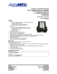
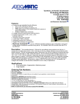
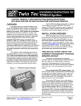
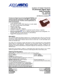
1
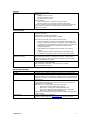
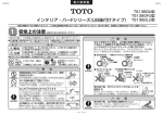
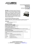
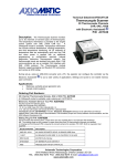
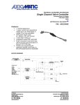
Technical Datasheet #TDAXDIO128 Discrete I/O P/N: AXDIO128 12 inputs, 8 relay outputs, SAE J1939 with Electronic Assistant® Description: The Discrete I/O Module reads 12 discrete inputs and sets 8 Form C relay outputs while networking with other CAN devices (SAE J1939) in a machine control system. The unit is a battery powered device with the ability to withstand engine cranking, reverse polarity and transient power conditions. In engine applications, information is provided to the engine control system using single-frame J1939 application-specific PDU2 type messages. Outputs can be controlled by any input or CAN message. A bi-color LED indicates operational status. The AXDIO128 has a number of setpoints that allow the user to configure it for their application. The Windows-based Electronic Assistant® can be used to configure the module over the CAN line. The setpoints can also be saved to a file and flashed into other AXDIO128 modules over the CAN bus. Alternatively, a RS-232 interface allows for quick user configuration adjustments using Windows HyperTerminal or other similar terminal software. Settings are saved to non-volatile memory upon command. A CANopen® model is available. The AXDIO128 features rugged packaging and watertight Deutsch IPD connectors for an IP65 rating. The module is UL recognized for UL508 (FTPM2) – Controls for Stationary Engine Driven Assemblies and has a cUL recognition as well. The control carries a CE mark for the EMC and RoHS Directives. The DIO Module meets the environmental, EMC and vibration requirements of generator set applications in marine installations and has type approvals from several marine societies (LR, DNV, ABS, etc.). Applications: Power Generator Sets, Diesel Engine Control Systems Ordering Part Numbers: SAE J1939 Discrete I/O Controller: AXDIO128 A CANopen® model is available as P/N AXDIO128CO. Electronic Assistant® P/N: AX070502 The configuration kit includes the following. USB-CAN Converter P/N: AX070501 1 ft. (0.3 m) USB Cable P/N: CBL-USB-AB-MM-1.5 12 in. (30 cm) CAN Cable with female DB-9 P/N: CAB-AX070501 AX070502IN CD P/N: CD-AX070502, includes: Electronic Assistant® software; EA & USB-CAN User Manual UMAX07050X; USB-CAN drivers & documentation; CAN Assistant (Scope and Visual) software & documentation; and the SDK Software Development Kit. Mating Plug Kit P/N: AX070200 This kit includes the following items. These items are also available from a local Deutsch IPD distributor. NB. The sealing plugs are only needed in cases where less than the 40 pins are required. Deutsch IPD P/N: Description: 0462-201-16141 48 16AWG SOCKETS SOLID 16-20AWG WIRE 6mm 114017 24 SEALING PLUGS SIZE 12-16 CAVITIES 12-18 AWG DRC16-40S 40-PIN PLUG, No Key DT06-08SA DT SERIES PLUG 8 CONTACT W8S WEDGELOCK FOR DT 8 PIN PLUG A crimping tool from Deutsch IPD is required to connect wiring to the sockets, P/N: HDT 48-00 or equivalent (not supplied). Technical Specifications Modules are designed for mounting on power generator sets or remotely up to 30 ft. Multiple AXDIO128 modules can be used on a CAN network. Inputs Power Supply Input Supply Current Protection Inputs Digital GNDs PGNs 12V or 24VDC nominal (9…32 VDC power supply range) At 12V: 90 mA + 50mA per active relay, typical At 24V: 50 mA + 30mA per active relay, typical Reverse polarity protection is provided. Power supply input section protects against transient surges and short circuits and is galvanically isolated from digital inputs and earth ground. Reads twelve (12) discrete inputs (active low with pull-up resistors) Input level characteristics: Low-Level input voltage: 0 to 0.8 V High-Level input voltage: 3.75 to +BAT Inputs have internal pull-up resistors. Input resistance: more than 5 kOhms The inputs have internal over and under voltage protection. Four digital GND pins are provided. AXDIO128 is an Arbitrary Address Capable ECU. It can dynamically change its network address in real time. The AXDIO128 supports: Address Claimed Messages (PGN 60928); Requests for Address Claimed Messages (PGN 59904); and Commanded Address Messages (PGN 65240). AXDIO128 supports Transport Protocol for Commanded Address messages (PGN 65240). It also supports responses on PGN Requests (PGN 59904). It transmits Software ID PGN65242 (-SOFT) only on request. AXDIO128 can constantly transmit the state of digital inputs in a user defined PDU2 PGN, set to proprietary B PGN 65440 by default. AXDIO128 can receive user defined PDU2 PGN controlling output relays, set to 65448 by default. AXDIO128 can receive mode select commands or send mode status feedback in a user defined PDU2 PGN, set to proprietary B PGN 65456 by default. There are two types of predefined structures for the data in the messages that are sent/received by the AXDIO128 for the I/O channels. With “compact” data, the structure is similar to PGN65241 (-AUXIO) where each channel has two bits per byte, resulting in up to four channels being read/controlled by one byte of data. However, if “expanded” data is used, each I/O channel is read/controlled by an individual byte in a message. The PGNs that are used for “Input State”, “Relay Control” or “Mode Select” messages used/recognized by the AXDIO128 are individually configurable by the user. TDAXDIO128 2 Outputs Outputs Sets 8 Form C relay outputs. Resistive load: 2A NO)/2 A (NC) at 277 VAC 2 A (NO)/2 A (NC) at 125 VAC 2 A (NO)/2 A (NC) at 30 VDC Dielectric strength: 4,000 VAC, 50/60 Hz for 1 min between coil and contacts 750 VAC, 50/60 Hz for 1 min between contacts of same polarity There is no special overcurrent/overvoltage protection on the relay outputs. The user is advised to provide a fast acting 3A fuse or an adequate external protection if necessary. Communication CAN Network Termination RS-232 1 CAN 2.0B port, protocol SAE J1939 Baud Rate: 250 bit/sec. Digital isolation is provided for the CAN line. A CANopen® model, P/N: AXDIO128CO, is available. Other features of the CAN communications interface include: It has two configurable “slew rates” to accommodate different CAN (SAE J1939) connections (and is capable of working both on the standard J1939 link between an engine controller and a generator controller, as well as on a J1939 accessory module link from a generator controller in power generation applications). Node address is auto configurable as per J1939-81 or per customer request. A watchdog timer to require a reboot when the microprocessor locks The AXDIO128 is designed to remain powered during engine cranking. According to the CAN standard, it is necessary to terminate the network with external termination resistors. The resistors are 120 Ohm, 0.25W minimum, metal film or similar type. They should be placed between CAN_H and CAN_L terminals at both ends of the network. 1 RS-232 port is available for debugging purposes. ASCII Text Format, 115200 Baud Rate Data – 8 bit, Parity – None, Stop – 1 bit. Flow Control – Xon/Xoff. Short circuit protection to ground. General Specifications Microprocessor Isolation Indicator SAE J1939 Profile User Interface TDAXDIO128 ADUC843 The power supply is galvanically isolated from digital inputs and earth ground. LED indicator remains RED when a network error occurs. It flashes green when the module is able to send messages over the bus but there is no network activity detected by the module. It stays ON and is GREEN when it is operating normally and is powered. For J1939 compliance (SAE, Recommended Practice for a Serial Control and Communications Vehicle Network, October 2007) all modules comply with the applicable portions of the following: SAE J1939-11, 15 – Physical Layer, Reduced Physical Layer SAE J1939-21, December 2006, Data Link Layer SAE J1939-71, January 2009, Vehicle Application Layer SAE J1939-73, September 2006, Application Layer – Diagnostics SAE J1939-81, May 2003, Network Management Customer specific proprietary extensions can also be included in the SAE J1939 profile on request. Electronic Assistant®, P/N: AX070502 Updates for the EA are found on www.axiomatic.com under the log-in tab. 3 Control Logic The AXDIO128 is designed to work either as a stand-alone module, or on J1939 CAN network. When connected to the network, it automatically recognizes network connection, claims a network address and can be configured to perform the following application tasks. Converts between physical I/O and CAN (SAE J1939) single frame commands Continuously broadcast the current state of digital inputs using a proprietary InputPGN Receive and process OutputPGNs to control DIO output relays The AXDIO128 can operate in one of four different modes: Normal Mode (CAN); Discrete Mode; Fault Mode; or Disabled Mode. Refer to the user manual for details. In Normal Mode, there are four ways the output can be configured to respond to the state of the control input (discrete input or CAN message): disabled; normal ON/OFF; inverted ON/OFF; or latched (changes state every time the control input transitions from OFF to ON). In Normal Mode, each output has four setpoints associated with it that determine the control input, control response, enable input and enable response for that relay. In Discrete Mode the relays can only be controlled be a discrete input wired to the module (no CAN). In Discrete Mode, there are an additional 2 setpoints for Control Input and Enable Input. In Fault Mode, the relay is driven to a particular state. In Disabled Mode, all output relays are de-energized. UL and cUL Compliance CE Compliance Vibration Marine Type Approval Operating Temperature Range Storage Temperature Range Humidity Protection Weight Enclosure Mating Sockets AXDIO128 uses Memory Access Protocol (MAP) for setpoint programming from the Electronic Assistant®. UL508 (April 2010) (FTPM2) – Controls for Stationary Engine Driven Assemblies cUL C22.2 No. 14-10 (2010) 2004/108/EC (EMC Directive) 2011/65/EU (RoHS Directive) 4.3 G for off-engine mounting The marine type approval process tested to 4.0 G per IEC 60068-2-6, Test Fc. Lloyd’s Register, DNV, ABS, RINA, GL, BV, CCS, IRS, RS The AXDIO128 meets the environmental, EMC and vibration requirements of generator set applications in marine installations. -40 to 85 ºC (-40 to 185 ºF) -50 to 120 ºC (-58 to 248 ºF) Protected against 95% humidity non-condensing, 30 ºC to 60 ºC IP67 Pollution Degree 3 rating per UL508 The marine type approval process tested to IP56. 2.73 lbs. (1.24 kg) Rugged aluminum housing, stainless steel end plates, neoprene gaskets 145.30 x 149.00 x 73.00 mm (5.72 x 5.86 x 2.87”) L x W x H Connectors, Deutsch IPD P/N: 1 8-pin DT13-08PA, 1 40-pin DRC13-40PB Use the following Deutsch IPD mating plugs to connect to the integral receptacles. Wiring to these mating plugs must be in accordance with all applicable local codes. Suitable field wiring for the rated voltage and current must be used. The rating of the connecting cables must be at least 70°C. Use field wiring suitable for both minimum and maximum ambient temperature. Receptacle Mating Socket (Refer to www.laddinc.com for more information on the wedgelock and contacts for this mating plug.) Power and CAN bus: DT13-08PA I/O Interface Receptacle: DRC1340PB DT06-08SA with wedgelock W8S DRC16-40SE-B DRC18-40SB DRC16-40S with sockets 0462-201-16141 Axiomatic offers a mating connector plug kit, P/N AX070200, that includes the 8 pin and 40 pin (unkeyed) plugs and sockets. TDAXDIO128 4 Electrical Pin Out – Power and CAN Electrical Wiring – I/O INPUT DIN LOAD GND LOAD OUTPUT NO TDAXDIO128 NC C 5 DIO Wiring - Typical TDAXDIO128 6 Electrical Pin Out – 40 Pin Connector Mating Connector Part Number: Deutsch IPD p/n DRC16-40SE-B or DRC18-40SB or DRC16-40S with sockets 0462-201-16141 Note: CANopen® is a registered community trade mark of CAN in Automation e.V. Specifications are indicative and subject to change. Actual performance will vary depending on the application and operating conditions. Users should satisfy themselves that the product is suitable for use in the intended application. All our products carry a limited warranty against defects in material and workmanship. Please refer to our Warranty, Application Approvals/Limitations and Return Materials Process as described on www.axiomatic.com/service.html. TDAXDIO128-10/22/15 TDAXDIO128 7