1
USER MANUAL
APG DYNAMIC PROCESSORS
LPMC216 - LPDS8 - LPDS12S LDSP15 - LPDS15S - LPMX4 LP3000C - LPSC25
SAFETY INSTRUCTIONS
This symbol alerts you to the presence of
un-insulated dangerous voltage inside
the enclosure – voltage that may be
sufficient to constitute a risk of shock.
This symbol wherever it appears, alerts
you to important operating and
maintenance instructions in the
accompanying literature. Read the
manual
CAUTION: To reduce the risk of electrical shock, do
not remove the cover (or back). No user serviceable
parts inside; refer servicing to qualified personnel.
WARNING: To reduce the risk of fire electrical
DO NOT EXPOSE TO WATER OR HUMIDITY
shock, do not expose this appliance to rain or
moisture.
INFORMATION ABOUT APPLIANCES SUPPLIED WITH POWER-CORD.
WARNING: APPLIANCE MUST HAVE GROUNDING
Cables are identified as follow:
Green/Yellow
Blue
Brown
Ground
Neutral
Phase
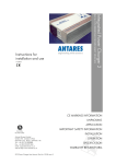
If colors of the power cable do not match with the cables’ color of the socket, please proceed as follow:
1
2
3
Green/Yellow wire must be connected to the wire identified with E letter or the ground sign.
Blue wire must be connected to the black wire or to the wire identified with N letter.
Brown wire must be connected to the red wire or the wire identified with L letter.
CONDUCTOR
L
N
E
PHASE
NEUTRAL
GROUND
COLOR
STANDARD
BROWN
BLUE
GREEN/YELLOW
WARNING: When no grounding exists, problems
OTHER
BLACK
WHITE
GREEN
may appear with the appliance or to the system
it is connected to in case of high tension
between casing and grounding. Serious injuries
or death could happen when simultaneous
contact occurs with case grounding and
electrical grounding.
FOR YOU OWN SAFETY PLEASE READ BELOW:
Water and moisture:
The appliance should not be used near water.
Ventilation:
The appliance should be situated so that its location or
position does not interfere with its proper ventilation.
It should not be placed on a surface that may block the
ventilation openings, or a built-in installation that may
impede the flow of air through the ventilation openings.
Heat:
The appliance should be situated away from heat sources
(radiators, amplifiers, etc.) that produce heat.
Power source:
The appliance should be connected to a power supply
only of the type described in the operating instructions or
as marked on the appliance.
Grounding or polarization:
Precautions should be taken so that the grounding or
polarization means of an appliance is not defeated.
Power-Cord Protection:
Power supply cords should be routed so that they are not
likely to be walked on or pinched by items placed upon or
against them, paying particular attention to cords and
User manual LP dynamic processor
plugs, convenience receptacles and the point where they
exit from the appliance.
Non-use Periods:
The power cord of the appliance should be unplugged
from the outlet when left unused for a long time.
Object and liquid Entry:
Care should be taken so that objects do not fall and
liquids are not spilled into the enclosure.
Damage Requiring Service:
The appliance should be serviced by qualified service
personnel when:
-the power cord or the plug has been damaged; or
-objects have fallen, or liquid has been spilled into; or
-the appliance has been exposed to rain; or
-the appliance does not appear to operate normally or
exhibits a marked change in performance; or
-this appliance has been dropped, or the enclosure
damaged.
Servicing: The user should not attempt to service the
appliance beyond that is described in the Operating
instructions. All other servicing should be referred to
qualified service person.
2
CONTENTS
INTRODUCTION........................................................................................................................ 3
SPECIFICATIONS ..................................................................................................................... 5
DESCRIPTION DES CONTROLS
FRONT PANEL .......................................................................................................................... 5
REAR PANEL............................................................................................................................. 8
User manual LP dynamic processor
2
INTRODUCTION
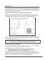
The LP processors provide all the necessary filtering, equalization, signal distribution and
dynamic protection for the operation of APG loudspeakers and systems. They are designed
to operate in conjunction with the Micro Axial Series, DISPERSION Series, BEAM Series &
SECTOR Series and APG subwoofers.
CONNECTING A PROCESSOR IN THE ELECTRO ACOUSTIC CHAIN
Dynamic processors must be connected as the last element before the power amplifiers.
In order to easily easy interface with other equipment, APG processors offer balanced inputs
and outputs on XLR connectors, in conjunction with a built-in hum loop eliminator.
Since the APG dynamic processors do not need a “Sense” or Return connection, it is
possible to connect several amplifiers and loudspeakers of the same type on a single unit, as
long as the audio signal is the same.
Amplifier gain must be set to 26dB gain to respect proper functioning of the actives
protections of the processors. Most of amplifiers allow this setting.
FREQUENCY RESPONSE PROCESSING
The LP processor includes a number of equalization stages in order to optimize the
frequency response of the loudspeakers included in a sound system.
Two different equalizations are available according to the intended application:
1
Position MON: near-field use (stage monitoring, distributed systems).
2
Position FOH: distant-field (Front-Of-House, long-throw).
For each position there is a set of LF shelving, HF shelving and 3 band parametric EQ.
The processor includes, on each output, a subsonic protection and a dynamic protection
including the 3 limiting parameters of operating loudspeakers: Displacement of the
diaphragm, Temperature of the moving coil, Power limit of amplifier (CLIP)
User manual LP dynamic processor
3
FILTERING AND SWITCHES
A "Mute" switch of the "HI" channels allows to temporarily cut the signal to the main
speakers.
The subwoofer channel offers the choice of two crossover transfer functions, a level control,
a subsonic protection and dynamic protection with the same three parameters control of the
loudspeakers.
The loudspeaker/subwoofer crossover is done with a 24dB/octave slope. The subwoofer
channel's upper crossover frequency is modified in accordance with the relative physical
placement of the subwoofers and the main speakers.
A switch allows choosing operation “with subs” or “without subs”.
Engaging the SUB switch introduces the necessary high-pass filtering of the main speakers.
The nominal cross-over frequency is comprised between 80 Hz and 110Hz depending on the
type of main speakers.
The subwoofer signal is either coming from the summation of left and right channels or from
an external signal (such as a dedicated auxiliary send)
DYNAMIC PROTECTIONS
The LP processor include three types of real-time active dynamic protections
- Cone or diaphragm excursion: if the displacement exceeds the elastic capacity of the
suspension, the loudspeaker gets damaged, ending in its destruction. An excursion
amplitude detection system monitors the displacement and adjusts, if necessary, the cutoff frequency of a sweeping high-pass filter, thus reducing the low frequency content of
the signal.
- Voice coil temperature: excessive power increases the temperature of the moving coil,
which can eventually burn. A temperature detection simulator, based on the thermal
capacity of the voice coil, limits the amplitude of the signal in case of overheating.
- Amplifier clipping: when reaching its limit (overload or clip), an amplifier loses its
capability to control the movement of the diaphragm, which then may get distorted or
collide with the polar pieces. Monitoring this limit is done in real time for any power rating
between 300 and 4000 W. As soon as the clipping threshold is detected, a limiter
reduces the amplitude of the signal.
- The combination of these dynamic protections ensures the system is used reliably at the
maximum of its capability. These three protection types are based on real-time
simulations of the operational limiting parameters of loudspeakers and amps.
- This process, contrary to a "sense return" type of control, can anticipate amplifier clipping
right at the processor, before any critical performance happens in the amplifier.
- In addition, this allows using only one processor for a string of amplifiers receiving the
same signal.
- Front-panel LED’s visualizing the operation of the various protection types, giving the
operator an indication of the safety margin of the system.
- Occasional blinking of LED's on transients does not impact the acoustic response of the
system, it merely indicates nearing its limits
- Permanent illumination of LED’s indicating the limits of the system are being exceeded
and damage may result if prolonged.
User manual LP dynamic processor
4
TECHNICAL DATA
SPECIFICATIONS:
Input:
Balanced on female XLR3 Pin, Ground 1 pin
Nominal level:
Impedance:
+4 dBu
20 kOhms
Output:
Balanced on male XLR, Pin 1 Ground
Maximum level:
Impedance:
+21 dBu
100 Ohms
Overall information:
Noise:
THD less than :
Connectors:
Consumption:
Frequency response:
-94 dBu (22Hz -22kHz)
0.01% (4 dBu, 1kHz)
XLR 3 pin, ground 1 pin
220/240VAC 15VA
Tailored to optimize frequency response of
APG Loudspeakers range
Mechanical :
Dimensions :
Net weight:
Front panel:
Coating/finish:
User manual LP dynamic processor
482,6 mm x 270 mm x 44 mm
4,5 kg
Aluminium 3 mm
Grey Epoxy
5
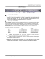
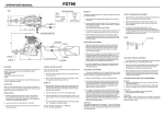
DESCRIPTION OF CONTROLS
FRONT PANEL
A)
1)
B)
SUBWOOFER SELECTOR:
Selection of type of subwoofer: The block of switches on the left allows the
selection of the type of subwoofer. The choice is based on the size of drivers and their
acoustic load: the labels "18" "15" "46" "38" refer to the products reference. The "S"
switch must be engaged if the subwoofer's reference includes one.
TOPOLOGY OF SYSTEM:
Local / Distant: This switch modifies the crossover frequency in accordance with the relative
position of the subwoofers and the main speakers. If the main speakers are stacked on the
subs or at less than 1.5 meter (5ft), the switch must be in the Local position. If the speaker is
at more than 1.5meter (as when installed on a pole), the switch must be pressed in the
Distant position.
Frequency crossover for subwoofer :
DS8
DS12S
DS15
DS15S
3000C
Local
110 Hz, 24 dB/Octave
110 Hz, 24 dB/Octave
80 Hz,24 dB/Octave
80 Hz, 24 dB/Octave
80 Hz,24 dB/Octave
Distant
130 Hz, 24 dB/Octave
130 Hz, 24 dB/Octave
95 Hz, 24 dB/Octave
95 Hz, 24 dB/Octave
95 Hz,24 dB/Octave
3)
Phase : When depressed, this push-button introduces a polarity reversal to
compensate wiring problems or acoustical phase reversals
4)
Align: the phase of the subwoofers relative to the main speakers can be aligned,
optimizing the system's crossover.
5) Sub Level: this potentiometer controls the level of the subwoofers. A center detent
indicates the nominal position. The range is from infinite attenuation to 6 dB gain.
User manual LP dynamic processor
6
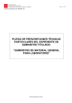
DESCRIPTION OF CONTROLS
FRONT PANEL
C) SYSTEM OPERATION:
6)
HF EQ: This pot controls the clarity of the system, adding or subtracting HF
energy via a "tilt" filter. The range is from -6 to +6 dB.
7)
MON/FOH: This switch engages equalization, optimized for near-filed applications
(stage monitor, distributed sound). In the FOH position, the equalization is adapted
for far-field (Front-Of-House, long-throw, high power)
8)
With Sub/No Sub: When engaged this switch inserts a High pass filter in the
main speakers providing the necessary cross-over function needed when
subwoofers are used.
9)
High ON/OFF: When released, this switch cuts the signal going to the main
speakers.
D) PROTECTIONS DISPLAYS :
Active mode protection does not alter sound reproduction.
10) PROTECTION: Each output incorporates a protection circuitry which simulates the
limiting parameters of the loudspeakers:
Excursion of the cone driver,
Temperature of the moving coil,
Clip of the amplifier.
A set of 3 LED's is used to indicate each operational parameter.
The LED's are activated when the operational parameters of the speaker are
approaching dangerous levels.
Flashing of the LED's indicate normal activity of the system.
Continuous lighting of LED's indicate that one or several parameter limits are
constantly exceeded, and that level should be reduced
11) CALIBRATION: This potentiometer is used to calibrate the anti-clip protection of
the SUB amp. (see chapter E)
12) CALIBRATION: This potentiometer is used to calibrate the anti-clip protection of
the main amps. (see chapter E)
E) CALIBRATION OF ANTI-CLIP PROTECTION:
Practical Calibration method:
Position the “Power” potentiometers at their maximum.
Using a signal featuring strong dynamics, increase the signal level until reaching
amplifier saturation ("clip") (most amplifiers comprise front panel clip LED's).
Pull down “Power” potentiometers until the amplifier leds switch off. Amplifier's LED's
must go off while the processor's Amp LED must light up.
Theoretical Calibration method:
Set the “Power” potentiometers on the position corresponding to the theoretical power
of the amplifier under 4 Ohms.
User manual LP dynamic processor
7
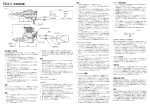
DESCRIPTION OF CONTROLS
REAR PANEL
13) Normal/Bridge: this switch must be engaged when using a bridged amp (32db
gain)
14) Sub Input: When this switch is released, the subwoofer derives its input from the
sum of inputs A and B; when it is engaged; it receives the signal from an external
source (such as a mixer's auxiliary send).
NB: For proper operation of the protection circuitry, the gain of the amplifiers must
be 26dB. Most amplifiers provide this gain as standard.
Warning: Excessive gain may result in speaker damage.
In particular, bridged amps exhibit a gain 6db higher than standard.
When using bridged amps it is necessary to use one of the following process:
Use the button normal/bridge situated on the rear panel
Modify the amp's gain structure,
Use a 6 db input attenuator,
Turn the amp's potentiometer down 6 dB
APG, TG29, TG32, attenuators & TGxx (custom made), for 29dB, 32dB or other value
are available on order.
All inputs and outputs are electronically balanced: the connectors are 3 pin XLR'S
The mains receptacle is an EEC type with the center prong connected to ground. For
obvious safety reasons, it should always be connected.
The processors can be operated continuously; thus they do not have a mains switch.
The processor uses a hum loop eliminator. If any hum or buzz occurs, it is not caused by a
ground loop
F) When replacing mains fuse, type & value must be identical as indicated bellow:
220-240Vac
0,1 A Temp.
100-126Vac
0,2 A Temp.
User manual LP dynamic processor
8
APG FRANCE – 19 Bis Rue des Ecoles – Site Valnor ZI Haute 95500 Le Thillay –RCS PONTOISE 451 935 084
T : +33(0)1.30.18.92.70 F : +33(0)1.30.18.92.71 - E-mail : [email protected] Web: www.apg.tm.fr