1
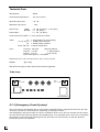
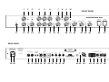
Please note:
In order to keep the file size small this PDF-File exists only of the internal pages of the
original manual which contains the important technical information!
The ENGL SOVEREIGN 100 is on the cutting edge of modern guitar technology, it
boasts a number of efficient features and operating modes: three channels, Clean, Crunch and
Lead equipped with three Gain controls and a several Sound pushbuttons. Clean channel
settings are variable from crystal-clear clean rhythm tone to loud high-gain tone ideal for clean
soloing. The other main channel delivers an abundance of crunch tones through to blistering
hi-gain Lead tones. Individual Volume controls for each channel and two separate voicing
sections access a vast arsenal of tones. The Crunch/Lead channel is also equipped with a
Presence Ratio control and a Depth Boost pushbutton: This combination delivers practical
poweramp treble and bass tuning options (in relation to the clean channel). Two different
crunch and lead distortion modes enhance this combo´s tonal spectrum at the touch of a
pushbutton: Rough for loads of upper-end grit and powerful bottom-end; Smooth for creamy
mids with plenty of punch. Yet another handy tool is the Master Volume featuring volume
switching; two different predetermined volume levels accessible via footswitch for that added
punch during soloing! This feature also enables you to boost the Clean channel for crisp clean
leads.
This amp also features a number of signal paths: a passive, parallel/serial (!) FX loop, a variable
balanced line out featuring speaker simulation and an overload LED. The integrated ECS
(Emergency Circuit System) protects the amp from damage due to power tube defects/failure
and ensures the amp continues to function at reduced power until the failed tube can be
replaced.
Superior craftsmanship and finishing and quality components are what this device is all about.
However keep in mind, that a few precautions will radically extend tube life (see handling and
care guidness).
PLEASE NOTE:
Read the Operator’s Manual carefully and thoroughly, especially the following Handling
and Care section as well as the framed guidelines. Avoid operating errors and potential
damage to the amp by heeding the guidelines and cautionary remarks in this manual. The
footnotes also cover a few convenient pointers and interesting tips on several functions.
These are listed at page 8 and 9 of the manual. This manual covers all the features, operational
guidelines, technical specifications and many helpful hints and tips. It should answer all your
questions, so keep it in a safe place and refer to it when necessary.
Handling and Care
Protect the amp from mechanical knocks (tubes!).
Let the amp cool down before you transport it (app.10 minutes).
Tubes need about 20 seconds to warm up after you switch the power on,
and furtheron a few minutes before they reach their full power capability.
Avoid storing the amp in damp or dusty rooms, they are hard on jacks,
switches and potentiometers.
Make sure air can circulate at the front and top of the amp
to allow for adequate cooling (increases component life).
Never operate the amp without an adequate load.
Replace tubes with select ENGL replacement tubes (special selection criteria) to avoid
microfonic properties, undesireable noise and unbalanced performance.
3
The last page contains a front- and backpanel illustration!
FRONT PANEL
1 GAIN .............................................................................................................................TIP
Input sensitivity control for the Clean channel.
1
2 BRIGHT (Lo/Hi) ............................................................................................................TIP
Alters the EQ by boosting the upper treble range in the Clean Channel;
effectiveness decreases at higher GAIN (1) settings.
2
3 MID SHIFT
Shifts the midrange in the Clean channel: press the pushbutton, and the mids are amplified
in the 1 to 2 kHz range.The degree of amplification depends a great deal on the
TREBLE control setting.
4 BASS .............................................................................................................................TIP
Bottom end voicing control for the Clean channel.
3
5 MIDDLE .........................................................................................................................TIP
Mid-range voicing control for the Clean channel.
3
6 TREBLE ..........................................................................................................................TIP
Upper range voicing control for the Clean channel.
3
7 REVERB
Reverb control, adjusts the portion of the reverb signal and increases reverb intensity in the
Clean channel if you rotate it clockwise; the reverb can be switched on/off via a footswitch (jack 31).
8 CLEAN BOOST .............................................................................................................TIP
Amplification boost for the Clean channel. This function can also be activated via the
footswitch jack 31; you can select two variations (refer to 31).
4
9 CLEAN VOL.
Volume control for the Clean channel. (in front of the FX loop, affects the SEND level)
10 CHANNEL
Main channel selector pushbutton for switching between Clean and Crunch or Lead,
depending on the CRUNCH/LEAD (21) setting. The green LED next to the CLEAN VOL. control
indicates the Clean channel is active. This function can also be activated via footswitch (jack 19)
in this case the channel selector pushbutton is deactivated.
11 INPUT
Unbalanced 1/4" input jack
12 GAIN
Input sensitivity control, functions as pre-gain for the Crunch and the Lead channel and
defines the amount or distortion in the Crunch channel.
13 LEAD BOOST
Boosts the degree of distortion in the Lead channel, with primary emphasis on the bottom end.
4
14 LEAD
Controls the amount of distortion in the LEAD mode; the GAIN (12) and LEAD controls
are used to define the relationship between the Crunch and Lead signals.
CAUTION: Extremely high gain and volume levels in the Crunch and Lead mode can produce
strong feedback. Avoid feedback squeals, they lead to hearing loss and damaged speakers!
15 BASS ...........................................................................................................................TIP
Bottom end voicing control for the Crunch/Lead channel.
5
16 MIDDLE ......................................................................................................................TIP
Mid-range voicing control for the Crunch/Lead channel.
5
17 TREBLE .......................................................................................................................TIP
Upper range voicing control for the Crunch/Lead channel.
5
18 ROUGH / SMOOTH ..................................................................................................TIP 6
Switches between two completely unique overdrive characteristics in the Crunch/Lead channel:
ROUGH: emphasis on high and low ends.
SMOOTH: emphasis on midrange, suppresses the gritty upper frequencies.
19 REVERB
Reverb control, adjusts the portion of the reverb signal and increases reverb intensity in the Crunch/Lead
channel if you rotate it clockwise; the reverb can be switched on/off via a footswitch (jack 31).
20 CRUNCH VOL.
Volume control for the Crunch channel. (in front of the FX loop, affects the SEND level)
21 LEAD VOL.
Volume control for the Lead channel. (in front of the FX loop, affects the SEND level)
22 CRUNCH/LEAD
Channel switching between Crunch and Lead. Yellow LED illuminates when the Crunch channel
is active, the red LED indicates the Lead mode (both LED´s next to the respective Volume controls).
Use this pushbutton to pre-select Crunch or Lead. This function can also be activated via footswitch
(at jack 30) in this case the channel selector pushbutton is deactivated.
23 PRESENCE RATIO ......................................................................................................TIP
This control defines the Treble response in the Crunch/Lead channel in relation
to the Clean-mode; therefore it only functions in the Crunch and Lead channel!
7
24 DEPTH BOOST
Boosts the bottom end in the poweramp and is assigned to the Crunch/Lead channel;
it is deactivated in the Clean channel.
25 MASTER
Master volume control for power amp output; the feature to switch between two Master volume
levels (Hi/Lo-Master Volume) can be accessed by means of a footswitch (See 31).
26 STAND BY
Poweramp standby switch. Use this feature during a break; the amp is ready ready to perform
at once, because there is no duration caused by the period to warm up the tubes. In order to
save energy, we recommend, to switch the amp off (27) during a longer pause.
27 POWER
AC power on/off
5
REAR PANEL
28 AC SOCKET
Connect AC cord here
ATTENTION: Ensure you use an intact AC cord with an insulated plug only!
Before you power the amp up, ensure the voltage value printed beside the
AC socket corresponds to the available current.
29 AC FUSE BOX
Contains mains fuse (rear chamber) and spare fuse (front chamber)
NOTE: Ensure replacement fuses bear identical ratings (refer to the table)!
30 FOOTSWITCH: CHANNEL; CRUNCH/LEAD ............................................................TIP
1/4" stereo jack for connecting a double footswitch, executes the following functions:
1.Main channel selection: CLEAN/CRUNCH or LEAD (mono terminal)
2.Channel selection: CRUNCH/LEAD (stereo terminal)
9
31 FOOTSWITCH: REVERB; VOLUME LEVEL SWITCHING .........................................TIP
1/4" stereo jack for connecting a double footswitch, executes the following functions:
1.Reverb on/off (mono terminal)
2.Switching between the two Master volume levels Hi and Lo (stereo terminal),
in combination with the CLEAN BOOST pushbutton (8): If the pushbutton is in the
off position, then only the volume for the Clean channel is increased.
If the CLEAN BOOST pushbutton is in the on position (depressed),
then the Clean channel is also boosted.
9
32 REVERB SPRING SEND
Signal output for the reverb spring. This output is connected to the input jack
of the reverb spring via a shielded cable with RCA connectors. (red plug)
33 REVERB SPRING RETURN
Signal input for the reverb spring. This input is connected to the output jack
of the reverb spring via a shielded cable with RCA connectors. (black plug)
34 F.X. LOOP SEND
Signal output for the Effects loop. Connect this output to a signal processor’s
input/return jack via a shielded cable with 1/4" plugs.
35 F.X. LOOP RETURN
Signal input for the Effects loop. Connect this input to a signal processor’s
output/send jack via a shielded cable with 1/4" plugs.
36 BALANCE
FX mix control for the Effects loop: Rotate the knob to the DRY position for the pure amp signal,
i.e. no effect on the signal. Turn clockwise to blend in an effect connected to the loop, to the dry
signal (parallel/passive). At the EFFECT position, only the wet signal, i.e. the signal sent from
the FX device is fed to the power amp (serial/passive).
NOTE: If no effects processor is connected to this loop, leave this control
in position DRY!
6
37 POWER TUBE FUSE
Fuse (refer to the description of the E.C.S. on page 10) for the left power tube (the far left tube
when viewed from the rear of the chassis); the LED above the fuse illuminates when this fuse is blown.
Replacement fuses (160 mAM) are located at the housing´s rear panel.
38 POWER TUBE FUSE
Fuse for the second power tube (second from left);
the LED above the fuse illuminates when this fuse is blown.
Replacement fuses (160 mAM) are located at the housing´s rear panel.
39 POWER TUBE FUSE
Fuse for the third power tube (second from right);
the LED above the fuse illuminates when this fuse is blown.
Replacement fuses (160 mAM) are located at the housing´s rear panel.
40 POWER TUBE FUSE
Fuse for the right power tube (the far right tube);
the LED above the fuse illuminates when this fuse is blown.
Replacement fuses (160 mAM) are located at the housing´s rear panel.
41 LEVEL
Signal level control for the frequency-corrected line output; it is used to match
the amp’s signal level at the LINE output to the mixing console or recorder’s input.
42 OVERLOAD
This LED denotes the LINE output is overloading; in this case,
reduce the signal’s level via the LEVEL control.
43 FREQU.-COMPENSATED LINE OUT (BALANCED) .................................................TIP
The frequency-corrected, balanced LINE output jack (XLR). (Pin 2 and 3 signal, Pin 1 = N.C. ).
Its signal simulates a 4 x 12" speaker cabinet.
9
44/45 POWERAMP OUTPUT: 4 OHM
4 ohms speaker output jacks; internal paralell signal path for the connection of one 4 ohms
or two 8 ohms cabinets (unplug the internal speaker before connecting an external cabinet!).
46/47 POWERAMP OUTPUT: 8 OHM
8 ohms speaker output jacks; internal paralell signal path for the connection of one 8 ohms
or two 16 ohms cabinets (unplug the internal speaker before connecting an external cabinet!).
48 POWERAMP OUTPUT: 16 OHM
Speaker output jack for the internal speakers or, alternatively you can connect
an external 16 ohms speaker cabinet.
NOTE: Never operate the amplifier without a sufficient load, otherwise you may
damage or destroy the power amp! Ensure your cabinet’s specifications match the
respective output’s specs.
Choose only one of the following cabinet options:
A. One 4 ohms cabinet connected to a 4 ohms jack (without the internal speakers!)
B. Two 8 ohms cabinets connected to the 4 ohms jacks (without the internal speakers!)
C. One 8 ohms cabinet connected to a 8 ohms jack (without the internal speakers!)
D. Two 16 ohms cabinets connected to the 8 ohms jacks (without the internal speakers!),
or an external 16 ohms cabinet and the internal speakers connected to the 8 ohms jacks.
When you unplug the cable for the external cabinet, ensure you plug the internal speakers
back into the 16 ohms jack!
E. Internal speakers only or an external 16 ohms cabinet to the 16 ohms jack only.
7
TIP 1
GAIN settings depend on what type of pickups are installed in your guitar. The recommended setting for
humbuckers or active pickups lies between the 11 and 2 o’clock positions, and 1 to 4 o’clock for single
coils, for a pure clean response. More over increased gain will produce a touch of overdrive in the
preamp.
If your pickups
are of the ultra-high output variety ( > 1V or 0dB ) you may have to back off the guitar’s
volume to
achieve a truly clean tone.
TIP 2
For crisp glassy tones, set the BRIGHT switch to the HI position. This setting boosts the treble response
of muddy pickups.
TIP 3
In order to familiarize with your amp and its clean tone, set these voicing controls between the 12 and 3
o’clock´s position. Try it on for size and then adjust the controls according to your personal taste and the
accustic properties of the room.
TIP 4
The CLEAN BOOTS function´s Lo position is ideal for crisp, clear clean tones. The Hi position, depending
on the GAIN control setting, is great for rhythm or crunch sounds that, due to the higher volume and
increased sustain, are also suitable for leads. In combination with the VOLUME LEVEL SWITCHING (V.L.S.)
function, the CLEAN BOOST is a very practical feature: If there is a footswitch or a looper system connected
to jack 31, you are able to boost the Clean channel in addition to a higher output volume level. To do this,
set the CLEAN BOOST pushbutton to the "on" position. In the "off" position of this button, only the volume
level is increased via the V.L.S. function.
TIP 5
To get an idea of the Crunch and the Lead tone of this amp, we suggest you set all tone control pots to
the 12 o’clock´s position and then adjust the sound according to your taste, and the room’s ambience.
TIP 6
The ROUGH sound character (heavy) is great for rhythm playing with a pronounced bottom end and
gritty, biting highs. You should use the BASS knob (15) and the DEPTH BOOST button (24) sparingly in
conjunction with this feature (especially if you connect a 4 x 12" cabinet) ; the PRESENCE RATIO control is
recommended between 10 and 2 o´clock´s position.
The SMOOTH sound character is most effective for lead-playing. In spite of its creamy tube tone, its
pronounced mids deliver enough punch to cut through! Try on PRESENCE RATIO settings between 11
and 3 o´clock and activate the DEPTH BOOST. Extremely high gain and volume levels can produce strong
feedback between the speakers and your guitar´s pick ups. Cut back on the GAIN, TREBLE and PRESENCE
RATIO settings to avoid undesirable feedback.
TIP 7
Harmonic distortion in the Crunch and Lead channels generates a broad spectrum of overtones, adding a
great deal of upper frequencies to the signal. The PRESENCE RATIO control reduces the amount of treble
in the poweramp in relation to the Clean treble setting. The PRESENCE RATIO control turned all the way
up is equal to the poweramp presence adjustment in the Clean channel. The adjustment of the PRESENCE
RATIO control depends on the selected sound character (see even TIP 6) the volume and your taste.
TIP 8
The switching functions CHANNEL (10), CRUNCH /LEAD (21), the REVERB (on/off) and the (MASTER-)
VOLUME LEVEL SWITCHING can also be executed via a Looper/switcher or other MIDI devices that
feature 4 freely-programmable switching inputs. Depending on the type of MIDI device, you may have
to split the FOOTSWITCH stereo jacks into two mono jacks. Each switching function requires the
mono or stereo contact (see 30 and 31 for assignments) and the ground!
NOTE! If the switching and signal grounds are identical in the MIDI device, then you may
encounter a ground loop, especially if the amp and device (e.g. FX processor) exchange signals!
8
TIP 9
The LINE OUT’s output level is influenced by the following factors: By the input level (GAIN), the
VOLUME control settings for the various channels, to some degree by voicing control settings, and by the
MASTER volume level. First dial in the desired sound combination at the front panel. Then adjust levels at
FX devices or signal processors (if connected). Now use the LEVEL control to adjust the LINE level. The
LINE output is not overloaded until the OVERLOAD LED illuminates brightly and continuously. You can
push the level up to this point to match a mixing console or recorder’s input level requirement. Use the
respective device’s input sensitivity or gain control to fine-tune level adjustments.
Additional TIP:
The SOVEREIGN 100 is equipped with removable wheels, which are located in the speakers housing and
packed separately when the amp is being delivered. You can incline the amp by removing the rear wheels,
to alter the response-angel of the speakers. Take care hereby, to straighten the front wheels in front
direction and in addition secure the combo against dropping (e.g. lean it against the corner, this usually
is also an advantage sound-wise).
Attention! Please read the following!
This guitar amplifier can produce high volume levels.
Exposure to high volume levels may cause hearing damage!
Leave tube replacement and power amp biasing to qualified professional.
Be sure the unit is switched off and unpluged!
Caution! Tubes can get very hot and cause skin burns.
Always use high quality cables.
Never operate the amp through an ungrounded outlet!
Never bridge a defective fuse and be sure replacement fuses feature
identical ratings!
Pull the AC mains plug before replacing fuses!
Never open the chassis or attempt repairs to your own. Consult qualified
service personnel!
Never expose the amplifier to extreme humidity or dampness!
Please read the instructions carefully before operating the unit!
Only operate the amplifier in a manner it is designed for and therefore
read this operational instructions!
9
Technical Data
Rated power:
100 W
Power Outlet Impedances :
4, 8 and 16 ohms
Minimum Input level:
- 43 dB
Maximum Input Level:
- 3 dB
Effects loop:
- 10 dB (average), - 3 dB (max.)
+ 3 dB (max.)
+ 3 dB (at 1kHz!)
SEND
RETURN
LINE output:
Levels are based on 0db => 1 V eff, measured at 1kHz.
Tubes:
V1 -> ECC83/7025 F.Q. (First Quality)
V2, V3, V4, V5 -> ECC83/12AX7 selected
V6 -> ECC83/12AX7 standard
V7, V8, V9, V10 -> 6L6 GC matched set
Fuses:
AC mains: 230 Volts
100 and 120Volts
external 2,5 AM
5 AM (medium)
internal 3,15 AT
6,3 AT (slow)
Power tubes (ECS): 2 x 160 mAM
Dimensions: (l x h x d) 69 x 54 x 32 cm (27,1 x 20,3 x 12,6 ")
Weight:
app. 36 kg
We reserve the right to make unannouced technical upgrades.
Tube array:
bulb
max. 15 W!
bulb
max. 15 W!
V7
V1
V2
V3
V8
V4
V5
V9
V 10
V6
output transformer
power transrormer
E C S (Emergency Circuit System):
This circuit ensures the amplifier does not shut down completely when a single power tube fails. The amp
continues to perform at reduced power, depending on the type of defect.
Gas developing in the power tubes can cause a momentary short circuit. The fuse activates, but the amp is
not shut down! Often the tube absorbs the developed gas, and is operable after a short circuit. Sometimes
the problem can be rectified by replacing the fuse, but if the new fuse activates as well, the defective
power tube needs to be replaced.
10
1
2
3
GAIN
BRIGHT
GAIN
4
5
6
7
8
BASS
MIDDLE
TREBLE
REVERB
9
10
CLEAN VOL.
CLEAN
BOOST
MID SHIFT
BASS
LEAD
MIDDLE
TREBLE
REVERB
FRONT PANEL
SOVEREIGN 100
CHANNEL
CRUNCH VOL.
LEAD VOL.
PRESENCE RATIO
STAND BY
POWER
26
27
MASTER
INPUT
LEAD
BOOST
11
12
13
CRUNCH/
LEAD
ROUGH /
SMOOTH
14
15
16
17
18
19
20
21
DEPTH
BOOST
22
23
24
25
REAR PANEL
VOLTAGE
FUSED
100-120 V
5A
220-240 V
2,5 A
REPLACE FUSE
ONLY WITH SAME TYPE
AND RATING !
CAUTION !
FOOTSWITCH
REVERB
SPRING
!
DO NOT OPEN !
RISK OF ELECTRIC SHOCK !
DO NOT EXPOSE THIS EQUIPMENT
TO RAIN OR MOISTURE !
SERIAL NUMBER:
F.X.LOOP
POWERAMP OUTPUT
OVERLOAD
WIRED FOR:
DRY
CHANNEL
CRUNCH / LEAD
28 29
REVERB
V. L.S.
SEND
EFFECT
RETURN
160 mA
SEND
RETURN
30 31 32 33 34 35
BALANCE
160 mA
160 mA
160 mA
POWER TUBE FUSES
36 37 38 39 40
100 W All-tube Guitar Combo Amp
SOVEREIGN 100, TYPE 740
MADE IN GERMANY
LEVEL
Optically refined by: CLARK / Meinerz
41 42
FREQ.-COMPENSATED
LINE OUT (BAL.)
43
4 OHM
8 OHM
PARALLEL
PARALLEL
16 OHM
44 45 46 47 48