1
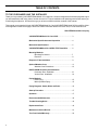
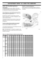
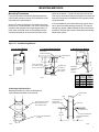
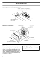
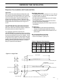
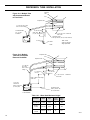
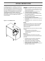
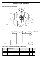
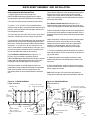
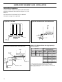
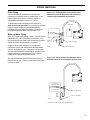
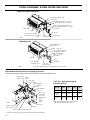
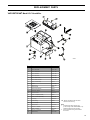
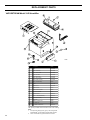
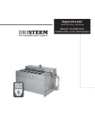
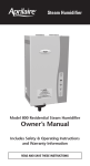
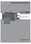
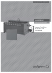
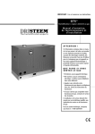
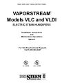
READ AND SAVE THESE INSTRUCTIONS ® VAPORSTREAM Models VLC and VLDI ELECTRIC STEAM HUMIDIFIERS Installation Instructions and Maintenance Operations Manual For Toll-Free Technical Support, Call 1-800-328-4447 UL LISTED CUL LISTED TABLE OF CONTENTS TO THE PURCHASER AND THE INSTALLER Thank you for purchasing VAPORSTREAM® Model VLC equipment. We have designed and built this equipment to give you total satisfaction and many years of trouble-free service. Proper installation and operating practices will assure you of achieving that objective. We therefore urge you to become familiar with the contents of this manual. This manual covers material for both VAPORSTREAM Model VLC and VAPORSTREAM Model VLDI humidifiers. Most of the application material will apply to both units. When information differs for the two units, it will be noted as such. DRI-STEEM Humidifier Company VAPORSTREAM Models VLC and VLDI .............................. 3 Mechanical Specifications and Capacities .......................... 4 Mechanical Specifications .................................................... 5 VAPORSTREAM Model VLC AREA-TYPE Humidifier ......... 6 Mounting Methods Mounting Procedures .................................................. 7 Electrical .................................................................... 8 Dispersion Tube Installation ................................................ 9 Optional Weather Cover ........................................................ 11 Weather Cover Dimensions ......................................... 12 RAPID-SORB® Assembly and Installation Horizontal Duct Installation ......................................13 Vertical Duct Installation ......................................... 14 Piping Methods Drain Piping ................................................................ 15 Make-up Water Piping ................................................. 15 Piping Diagrams: Steam, Water and Drain .......................... 16 Start-up Procedure ................................................................ 17 Operation ............................................................................... 17 Recommended Maintenance ................................................ 18 Trouble-Shooting Guide ....................................................... 18 Replacement Parts ................................................................ 19 Maintenance Service Record ................................................ 21 Two-Year Limited Warranty .................................................. 23 2 VAPORSTREAM® MODELS VLC AND VLDI VAPORSTREAM VLC Electric Humidifier State-of-the-art technology in a simple, low-maintenance humidifier. Duct This humidifier is designed to be used with either softened or unsoftened water (preferably softened). The probe-type level control system requires water conductivity of 100 micromhos/cm (2 grains/gal) minimum to function, and therefore will not operate on water treated by reverse osmosis or deionization. However, VAPORSTREAM® Model VLC humidifiers are available for use with these water types. The standard humidifier can be converted in the field to a VLDI model. See below. Dispersion Tube Thermal Cut-Out Raised Heater Cover Cover Knobs Evaporating Chamber Skimmer Port Outlet Fill Valve Needle Valve Manual or Electric Drain Valve VAPOR-LOGIC® Clean-out Tray Probes Control Cabinet OM-628 VAPORSTREAM VLDI Option Cover Knobs Cover For use with deionized or reverse osmosis water. This unit produces chemical-free steam and reliable, accurate humidification control. It is virtually maintenance-free with no wasted water, no wasted heat, and very little or no downtime. Overflow Float Valve Low-Water Cut-Off 3/4" SST Drain Valve OM-1000 3 MECHANICAL SPECIFICATIONS AND CAPACITIES Table 4-1: Mechanical Specifications and Capacities Steam capacities p er h o u r Model number Current draw (amps) (A) Heaters kW Single-phase L b s. Three-phase** K g. Qty. Stages* 120V 208V 240V 480V 600V 208V 240V 480V 600V VLC/VLDI 2-1 5.7 2.6 1 1 16.7 9.6 8.3 4.2 3.3 2 3-1 8.6 4.0 1 1 25.0 14.4 12.5 6.3 5.0 3 4-1 11.4 5.2 1 1 33.3 19.2 16.7 8.3 6.7 4 5-1 15.2 6.9 1 1 25.6 22.2 11.1 8.9 5.33 VLC/VLDI 6-1 17.1 7.8 3 1 28.8 25.0 12.5 10.0 16.7 14.4 7.2 5.8 6 9-1 25.7 11.7 3 1 43.3 37.5 18.8 15.0 25.0 21.7 10.8 8.7 9 12-1 34.2 15.5 3 1 25.0 20.0 33.3 28.9 14.4 11.5 12 16-1 45.6 20.7 3 1 33.3 26.7 44.4 38.5 19.2 15.4 16 21-1 59.9 27.2 3 1 43.8 35.0 25.3 20.2 21 25-1 71.3 32.3 3 1 41.7 30.1 24.1 25 VLC/VLDI 12-2 34.2 15.5 6 2 57.7 50.0 25.0 20.0 33.3 28.9 14.4 11.5 12 18-2 51.3 23.3 6 2 86.5 75.0 37.5 30.0 50.0 43.3 21.7 17.3 18 24-2 68.4 31.0 6 2 50.0 40.0 66.6 57.7 28.9 23.1 24 32-2 91.2 41.4 6 2 66.7 53.3 88.8 77.0 38.5 30.8 32 42-2 119.7 54.3 6 2 87.5 70.0 50.5 40.4 42 50-2 142.5 64.6 6 2 83.3 60.1 48.1 50 VLC/VLDI 18-3 51.3 23.3 9 3 86.5 75.0 37.5 30.0 50.0 43.3 21.7 17.3 18 27-3 77.0 35.0 9 3 129.8 112.5 56.3 45.0 74.9 65.0 32.5 26.0 27 36-3 102.6 46.5 9 3 75.0 60.0 99.9 86.6 43.3 34.6 36 48-3 136.8 62.1 9 3 100.0 80.0 133.2 115.5 57.7 46.2 48 63-3 179.6 81.5 9 3 131.3 105.0 75.8 60.6 63 75-3 213.8 97.0 9 3 125.0 90.2 72.2 75 VLC/VLDI 24-4 68.4 31.0 12 4 115.4 100.0 50.0 40.0 66.6 57.7 28.9 23.1 24 36-4 102.6 46.5 12 4 173.1 150.0 75.0 60.0 99.9 86.6 43.3 34.6 36 48-4 136.8 62.1 12 4 100.0 80.0 133.2 115.5 57.7 46.2 48 64-4 182.4 82.7 12 4 133.3 106.7 177.6 154.0 77.0 61.6 64 84-4 239.4 108.7 12 4 175.0 140.0 101.0 80.8 84 100-4 285.0 129.3 12 4 166.7 120.3 96.2 100 * Heater stage identifies the number of contactors. ** Three-phase power supply connection. All heater loads are wired delta. Capacity Notes Approximately 172 BTUs (400 kJ) are required to raise the temperature of one pound (Kg) of water from 40° to 212° F (4° to 100°C). An additional 970 BTUs (2250 kJ) are required to change one pound (Kg) of water to water vapor. The addition of ¾" (25 mm) rigid foil faced fiberglass insulation (optional) on all surfaces of evaporating chamber will increase unit efficiency by approximately 2%. 4 Another factor to consider is condensation steam loss from hoses and tubes. Use the following steam loss guidelines: • vapor hose: 0.15 lbs/ft/hr (223 g/m/h) • insulated pipe: 0.05 lbs/ft/hr (74 g/m/h) • dispersion tubes: 0.5 lbs/ft/hr (744 g/m/h) MECHANICAL SPECIFICATIONS Table 5-1: Mechanical Specifications mm Weight empty (lbs) Weight empty (kg) Weight full (lbs) Weight full (kg) Control cabinet sizes 7.52 190 35 16 79 36 M 430 7.52 190 35 16 79 36 M 430 7.52 190 35 16 79 36 M 16.85 430 7.52 190 35 16 79 36 M 560 18.38 465 12.85 325 57 26 157 71 M A (width) B (height) C (length) Model Number in. mm in. mm in. VLC/VLDI 2-1 20.25 515 16.85 430 3-1 20.25 515 16.85 4-1 20.25 515 16.85 5-1 20.25 515 VLC/VLDI 6-1 22.00 9-1 22.00 560 18.38 465 12.85 325 57 26 157 71 M 12-1 22.00 560 18.38 465 12.85 325 57 26 157 71 M 16-1 22.00 560 18.38 465 12.85 325 57 26 157 71 M 21-1 22.00 560 18.38 465 12.85 325 57 26 157 71 M 25-1 22.00 560 18.38 465 12.85 325 57 26 157 71 M VLC/VLDI 12-2 22.00 560 18.38 465 20.35 515 79 36 237 108 M 18-2 22.00 560 18.38 465 20.35 515 79 36 237 108 M 24-2 22.00 560 18.38 465 20.35 515 79 36 237 108 M 32-2 22.00 560 18.38 465 20.35 515 79 36 237 108 M 42-2 22.00 560 18.38 465 20.35 515 79 36 237 108 M 50-2 22.00 560 18.38 465 20.35 515 79 36 237 108 M VLC/VLDI 18-3 22.00 560 18.38 465 27.85 705 110 50 326 148 L 27-3 22.00 560 18.38 465 27.85 705 110 50 326 148 L 36-3 22.00 560 18.38 465 27.85 705 110 50 326 148 L 48-3 22.00 560 18.38 465 27.85 705 110 50 326 148 L 63-3 22.00 560 18.38 465 27.85 705 110 50 326 148 L 75-3 22.00 560 18.38 465 27.85 705 110 50 326 148 L VLC/VLDI 24-4 22.00 560 18.38 465 35.35 900 153 70 427 194 XL 36-4 22.00 560 18.38 465 35.35 900 153 70 427 194 XL 48-4 22.00 560 18.38 465 35.35 900 153 70 427 194 XL 64-4 22.00 560 18.38 465 35.35 900 153 70 427 194 XL 84-4 22.00 560 18.38 465 35.35 900 153 70 427 194 XL 100-4 22.00 560 18.38 465 35.35 900 153 70 427 194 XL * Refer to table 5-2 for Control Cabinet dimensions Figure 5-1: Dimensions A C B Back View Front View Side View OM-626 Table 5-2: Control Cabinet Dimensions Size Inches mm Shipping weight* M 14 w x 16h x 6d 355 w x 400 h x 150d 32 lbs. 15 kg L 20w x 20h x 7d 500 w x 500 h x 180d 55 lbs. 25 kg XL 24w x 24h x 7d 600w x 600h x 1180d 73 lbs. 33 kg * In addition to the shipping weight of the humidifier. 5 VAPORSTREAM® MODEL VLC AREA-TYPE HUMIDIFIER Figure 6-1: Principle of Operation Steam created in the evaporating chamber (1) flows up through the chute (2), and is distributed into the space (3) via the fan. AREA-TYPE Humidifier Application Information The operating characteristics of AREA-TYPE steam humidifiers should be considered when selecting humidifier capacities and choosing mounting locations. Fan Steam discharge from the humidifier quickly cools and turns to visible, warm, microscopic drops or particles of water (fog) which are lighter than air. Should this fog contact any solid surface (columns, beams, ceiling, pipes, etc.) before it disappears, it may collect and drip, as water. Steam Chute The greater the space relative humidity, the higher and farther the "fog" will carry and rise in the space before disappearing. The table at right states the vertical (rise), horizontal (throw), and width (spread) dimensions that can be expected with the AREA-TYPE humidifiers. To avoid steam impingement on surrounding areas, these dimensions should be observed. Heaters Note: Tank dimension "C," in figure 5-1 on page 5, must be at least 12.85" (325 mm) and output should not exceed 285 lbs/hr (130 Kg/h). OM-681 Table: 6-1: Minimum Distance for Rise, Spread and Throw Space temp. Space RH 30% 60° F 16° C 40% 50% 30% 70° F 21° C 40% 50% 6 50 lbs/hr 20 kg/hr 100 45 lbs/hr kg/hr 150 lbs/hr 65 kg/hr 200 lbs/hr 90 kg/hr 250 lbs/hr 110 kg/hr 285 lbs/hr 130 kg/hr Rise 1 ft. 0.5 m 4 ft. 1.5 m 6 ft. 2.0 m 7 ft. 2.5 m 8 ft. 2.5 m 9 ft. 3.0 m Spread 2 ft. 1.0 m 4 ft. 1.5 m 5 ft. 2.0 m 7 ft. 2.5 m 8 ft. 2.5 m 9 ft. 3.0 m Throw 6 ft. Rise 1 ft. 2.0 m 10 ft. 3.0 m 12 ft. 4.0 m 13 ft. 4.0 m 15 ft. 5.0 m 17 ft. 5.5 m 0.5 m 4 ft. 1.5 m 6 ft. 2.0 m 8 ft. 2.5 m 9 ft. 3.0 m 10 ft. 3.0 m Spread 2 ft. 1.0 m 4 ft. 1.5 m 5 ft. 2.0 m 7 ft. Throw 6 ft. 2.0 m 10 ft. 3.0 m 12 ft. 4.0 m 14 ft. 2.5 m 9 ft. 3.0 m 10 ft. 3.0 m 4.5 m 16 ft. 5.0 m 18 ft. 5.5 m Rise 1 ft. 0.5 m 4 ft. 1.5 m 6 ft. 2.0 m 8 ft. 2.5 m 9 ft. 3.0 m 10 ft. 3.0 m Spread 2.5 ft. 1.0 m 5 ft. 2.0 m 5 ft. 2.0 m 7 ft. Throw 6 ft. 2.0 m 10 ft. 3.0 m 12 ft. 4.0 m 14 ft. 2.5 m 9 ft. 3.0 m 10 ft. 3.0 m 4.5 m 16 ft. 5.0 m 18 ft. 5.5 m Rise 1 ft. 0.5 m 3 ft. 1.0 m 4 ft. 1.5 m 5 ft. 2.0 m 5 ft. 2.0 m 7 ft. 2.5 m Spread 1.5 ft. 0.5 m 3 ft. 1.0 m 4 ft. 1.5 m 5 ft. 2.0 m 5 ft. 2.0 m 7 ft. 2.5 m Throw 4 ft. 1.5 m 8 ft. 2.5 m 10 ft. 3.0 m 11 ft. 3.5 m 12 ft. 4.0 m 14 ft. 4.5 m Rise 1 ft. 0.5 m 3 ft. 1.0 m 4 ft. 1.5 m 5 ft. 2.0 m 6 ft. 2.0 m 7 ft. 2.5 m Spread 2 ft. 1.0 m 3 ft. 1.0 m 4 ft. 1.5 m 5 ft. 2.0 m 6 ft. 2.0 m 7 ft. 2.5 m Throw 4 ft. 1.5 m 8 ft. 2.5 m 11 ft. 3.5 m 12 ft. 4.0 m 13 ft. 4.0 m 15 ft. 5.0 m Rise 1 ft. 0.5 m 3 ft. 1.0 m 4 ft. 1.5 m 5 ft. 2.0 m 5 ft. 2.0 m 7 ft. 2.5 m Spread 2 ft. 1.0 m 3 ft. 1.0 m 4 ft. 1.5 m 5 ft. 2.0 m 5 ft. 2.0 m 7 ft. 2.5 m Throw 4 ft. 1.5 m 8 ft. 2.5 m 11 ft. 3.5 m 12 ft. 4.0 m 14 ft. 4.5 m 16 ft. 5.0 m MOUNTING METHODS Mounting Procedures For proper operation of the electrode probe water level control and the skimmer system, the humidifier must be mounted level in both directions. settles to the bottom. A clean-out tray on the floor of the tank may be removed periodically through the front clean-out opening. Allow space for withdrawal of the tray when installing the humidifier. Access,18" minimum (460 mm), for periodic removal of the top cover is recommended. The cover is removed for inspection and cleaning of the evaporating chamber. In most cases, scale that forms on the heating elements continuously flakes off as it forms and the loose scale In some installations, an overflow drain pan may be necessary to prevent possible damage to flooring. This may be caused by a rapid or sudden drainage of the contents of the humidifier. The drain pan must be connected to the sanitary waste water system. Figure 7-1: VLC Mounting Methods 1. Floor Stand Method 2. Trapeze Hanger Method 3. Wall Brackets Method 24 ¾" (630 mm) Secure rods to overhead construction Steam Dispersion Tube DRI-STEEM support legs (optional) Provide 18" (460 mm) min. clearance under duct for cover removal Threaded rod of size required Angle or channel of size required Cleanout OM-646 A DRI-STEEM wall brackets (optional) 2 required OM-648 Dimensions Dimensions for A for A (in inches) (in mm) Unit OM-647 4. Mounting Unit Below Duct Mounting humidifier 18" (460 mm) below duct is recommended to facilitate cover removal. 3 heater 19 480 6 heater 19 480 9 heater 30 760 12 heater 36 915 Steam Dispersion Tube Clamp Cut hole in duct large enough to allow passage of hose clamp Two-piece Escutcheon Plate fastens to bottom of duct (duct omitted for clarity) Vapor Hose Bottom of Duct Cover of VAPORSTREAM Humidifier OM-65 ® 18" min. (460 mm) 2 piece Escutcheon Plate Cover of VAPORSTREAM Humidifier OM-66 7 MOUNTING METHODS 5. Mounting Units Away from Duct(s) Using Vapor Hose Vapor hose. (Pitch back min. 2" per foot (165 mm/m) to humidifier with supports to prevent sagging.) Maximum length 10' (3 m). Humidifier must be mounted level. OM-638 Stainless steel dispersion tube in middle of duct. Pitch as shown in figure 9-1 on page 9. 6. Mounting In Air Handling Unit Gasketed Access Door Outdoor and Return Airflow into Air Handling Unit Air Handling Unit Casing Airflow Filter and Mixing Box Air Handling Unit Coil Section Supply Air Duct Set unit level. Locate unit so that steam dispersion assembly is in the most active part of the air stream. Humidifier Centered in Air Handling Unit OM-653 Electrical The current characteristics, and capacity requirements should be checked against the nameplates. The control cabinet should be mounted in a location convenient for service. All wiring must be in accordance with all local codes, and with VAPORSTREAM® Model VLC wiring diagram. The diagram is inside the control cabinet. The wiring between the control cabinet and humidifier must be rated at 105°C minimum. 8 Caution: Only qualified electrical personnel should perform installation procedures. DISPERSION TUBE INSTALLATION Dispersion Tube Installation with Condensate Drain Vapor Hose When a vapor hose and stainless steel dispersion tube are used, they should be pitched back to the humidifier. A minimum slope of 2" per foot (165 mm/m) (with no “low spots”) is recommended. Vapor hose should be supported to prevent sags or low spots. When this is not possible due to duct elevation or an obstruction, alternate arrangements should be used as shown in figure 15-1 or 15-2. Any condensate that forms in the vapor hose must be removed. Preferably, it should be returned to an open drain with a water seal of sufficient height to contain the duct static pressure, as shown in figure 10-1. The condensate can also be returned to the VAPORSTREAM® VLC, as shown in figure 10-2, with an air vent. This method requires a water seal and an air gap to prevent back pressure from the VLC chamber. Excessive back pressures imposed on the humidifier may lead to dispersion tube(s) spitting, lost water seals, or leaking gaskets. When the distance between the humidifier and the dispersion tube(s) exceeds 10 feet (3 m), consult factory for special recommendations. Hard Piping (when used) • Hard piping should have a minimum I.D. of 1½" (35 mm). • A minimum pitch of 2" per foot (165 mm/m) back to the humidifier must be maintained. • 90° elbows are not recommended; use two 45° elbows one foot apart instead. • Thin-walled tubing will heat up faster and cause less start up loss than heavy-walled pipe. • Insulating the rigid piping will reduce output loss due to condensation. Tube Mounting • Mount dispersion tubes pitched as stated above. • Tubelets must discharge perpendicular to air flow. • Return line piping material must be suitable for 212°F (100°C) water. Min. Condensate Drain Line Sizing • One or two tubes: 3/4" (20 mm) I.D. • Three or more tubes: 1" (25 mm) I.D. Table 9-1: Dispersion Tube Capacities Capacity Tube Without With A B Dia. Drain Drain 1½" 28 lbs/hr 57 lbs/hr 3.25" 1.51" (38 mm) (13 Kg/h) (26 Kg/h) (85 mm) (40 mm) 2" 57 lbs/hr 85 lbs/hr 5.00" 2.03" (50 mm) (26 Kg/h) (39 Kg/h) (130 mm) (50 mm) Figure 9-1: Single Tube Insertion Length 2.5" (65 mm) A A 2"/ft (165 mm/m) Pitch Mounting Nut Pre-molded High Temperature Resin Steam Tubelets A A 1/8"/ft (10 mm/m) Pitch "B" Dia. (TYP) Mounting Nut 3.25" (85 mm) .625 Dia. 3.25" (85 mm) ¼" NPT Coupling ½" O.D. Stainless Steel (condensate drain) Movable Duct Plate (Can be mounted within limits of 2.5" (65 mm).) OM-351 9 DISPERSION TUBE INSTALLATION Dispersion Tube Figure 10-1: Multiple Tube with Condensate Wasted to Floor Drain Duct Dispersion Tube 1-½" (38 mm) Dia. Vapor Hose or Hard Tubing* 6" (150 mm) Min. VAPORSTREAM ® VLC or VLDI Humidifier Water Seal (5" (125 mm) approx.) ½" (50 mm) O.D. Condensate Drain Tube Condensate Drain Tube by Others** (3/4" (20 mm) minimum) Air Gap *Refer to local codes for drain pipe sizing requirements. Floor Drain* OM-696 Figure 10-2: Multiple Tube with Condensate Return to Humidifier Dispersion Tube Duct Dispersion Tube 1-½" (38 mm) Dia. Vapor Hose or Hard Tubing * 6" (150 mm) Min. Water Seal (5" (125 mm) approx.) ½" (13 mm) Air Vent ½" (50 mm) O.D. Condensate Drain Tube Refer to Water Seal Height, Table 10-1 ¾" (20 mm) Condensate Return Connection (on face plate) Condensate Drain Tube by Others, 3/4" (20 mm) Minimum VAPORSTREAM VLC or VLDI Humidifier Table 10-1: Water Seal Minimum Height* Humidifier Lbs/Hr Kg/h Height (Inches) Height (mm) Up to 48 KW 5-138 2-62 12 305 49 KW to 64 K W 139-183 63-83 15 380 65 KW to 100 K W 184-227 84-103 18 460 OM-697 * Height required to overcome humidifier internal pressure. 10 OPTIONAL WEATHER COVER A weatherproof enclosure is available, as an option, for the VAPORSTREAM® VLC. This weather cover is available in either galvanized or stainless steel and comes in four sizes, designed to fit over a 3, 6, 9, or 12 heater VLC (see figure 12-2 for dimensional data on the four sizes). The weather cover encloses the VLC to protect it from wind and water, and is ETL listed to conform to UL standard 988. The weather cover is fully assembled at the DRI-STEEM factory and is available with a remotely mounted controller. Figure 11-1: VLC Weather Cover Instructions for Installation (See Page 12, Figures 12-1 and 12-2): 1. Remove the weather cover top and panels C and D to access the water and electrical connections. A 7/16" socket wrench is required. 2. Connect water supply and drain piping (panel C). 3. Terminate main power to unit (panel D). 4. Check the hose cuff(s) and hose clamp(s) for looseness created during shipment. 5. Re-attach the weather cover top and panels C and D which were removed in step #1. 6. Check that all bolts are securely fastened. 7. Connect steam dispersion device(s) to the outlet(s) on the humidifier. 8. Verify that a good seal is maintained after making the connections. NOTES: The bottom of the weather cover is open to accomodate piping and electrical connections. These connections must be run in watertight plastic conduit due to the outdoor environment. Other modifications may need to be made by the installer including: • freeze protection on all water piping • insulation of hard piping between humidifier and dispersion device Maintenance: Periodic maintenance of the weather cover itself is recommended in order to insure it's continued wind/water proof state. 1. Periodically check the condition of the gasket(s). Replace as needed or on an annual basis. 2. Annually check for loose bolts or connections. 3. Annually check the hose cuff(s) for signs of wear. Replace as needed or on an annual basis. 4. Annually check the cover for any signs of corrosion or degradation. Repair as needed. 11 WEATHER COVER DIMENSIONS Figure 12-1: Weather Cover Exploded View Top Panel Panel A Panel B Panel C OM-906A Panel D Figure 12-2: Weather Cover Dimensions Panel Identification Label C B ETL Certification Label Product Identification Label A D OM-904 Table 12-1: 3, 6, 9, and 12 Heater Overall Dimensions of Weather Cover Figure 12-2: Callout Letter 12 Callout Description Three Three (inches (mm) Six (inches Six (mm) Nine (inches) Nine (mm) Twelve (inches) Twelve (mm) A H ei ght 50¾ 1290 50¾ 1290 50¾ 1290 50¾ 1290 B Length 23½ 600 32 815 40 1015 47½ 1205 C Width 25 635 23½ 600 23½ 600 23½ 600 D Distance from bottom 7¾ 200 7¾ 200 7¾ 200 7¾ 200 RAPID-SORB® ASSEMBLY AND INSTALLATION Check that the dispersion tubes discharge steam perpendicular to the air flow. Secure tubes to the overhead channel. Secure the channel to the duct. Position hose cuffs or slip couplings over tube and header tube nipples, and secure with clamps. Instructions for Horizontal Duct 1. Unpack shipment and verify receipt of all RAPID-SORB components with packing list. Report any shortages to the DRI-STEEM factory immediately. 2. Provide necessary access in and around duct work. 3. Locate 1" x 1½" (25 mm x 38 mm) stainless steel channel inside the duct. Hang the channel from the top of the duct, centered between duct side walls, with the two mounting holes provided. 4. If hose cuffs are used, slide cuffs over the open end of each tube. Install a pair of hose clamps on each tube. 5. Note direction of air flow within duct, then arrange each dispersion tube so steam will discharge perpendicular to the air flow. Use the hex bolts provided to attach tubes to overhead 1" x 1½" (25 mm x 38 mm) channel. Do not secure. If the header is outside the duct (see figure 13-2), punch-out necessary clearance holes in the base of the duct to slide dispersion tubes up from bottom. 6. For a Header Inside the Duct (See figure 13-1.): Punch or cut out necessary clearance holes for RAPID-SORB header. Slide header into the duct, position header and slide the dispersion tube hose cuffs or slip couplings over the header dispersion tube nipples. Position the header so vertical dispersion tubes are perpendicular to duct and pitch the header to condensate drain. Secure header to the mounting bracket. Use escutcheon plates to secure header where it enters the duct. 1" x 1-1/2" (25 mm x 38 mm) S.S.T. Channel (by DRI-STEEM) Orificed Tubelets Duct or Casing Slip Coupling or Hose Cuff Nut and Bolt Pitch 1/8" per foot (10 mm/m) minimum Header Optional Companion Flange or Threaded Connection for Hard Piping OM-101 Condensate Drain,3/4" NPT 3/4" (20 mm)Copper Air Gap *Open Drain Position the header so dispersion tubes are perpendicular to duct and pitch the header to condensate drain. Secure dispersion tubes in place with the tube escutcheon plates provided. Check the position of the tubes for steam release perpendicular to the air flow. Secure tubes to the overhead channel, and secure channel to the duct. With header pitched to condensate drain, slip hose cuffs or slip couplings over tube nipples and secure with clamps. 7. Connect a condensate drain to the header, provide the water trap as shown, and run to open drain, sized according to local codes. 8. Attach the header steam supply connector to main header using the hose cuff and clamps provided, but do not secure. 9. Route the necessary number of vapor hoses or pipes from the humidifier tank, position connector to accept the hoses or pipes and secure. Note: Refer to page 15 for vapor hose information on routing and for alternate vapor hose installation methods. Figure 13-2: RAPID-SORB Unit Header Under Duct Figure 13-1: RAPID-SORB Unit Header Inside Duct Dispersion Tube For a Header Outside the Duct (See figure 13-2.): Position header under dispersion tubes, then slide hose cuffs or slip couplings over header dispersion tube nipples. 5" (125 mm) Min. 6" (150 mm) Min. Top of Duct or Casing Mounting Channel 3/8-16 x ½" Hex Head Bolt View A-A Orificed Tubelets Slip Coupling or Hose Cuff Dispersion Tube A 1" x 1-1/2" (25 mm x 38 mm) S.S.T.Channel (by DRI-STEEM) Duct A Escutcheon Plate Mounting Nut Pitch 1/8" 6" (150 Condensate per foot mm) Min. (10 mm/m) Drain, 3/4" NPT Hose Cuff minimum 3/4" (20 mm) 5" and Clamps Copper (125 Air Gap mm) Min. *Open Drain VAPORSTREAM® Model VLC Humidifier * Refer to local codes for drain pipe size requirements. OM-102 13 RAPID-SORB® ASSEMBLY AND INSTALLATION Vertical Duct Installation Install the RAPID-SORB with dispersion tubes and header pitched to condensate drain as shown in figures 14-1,14-2, and 14-3. See "Instructions for Horizontal Duct" for additional information on page 13, as applicable. Figure 14-1: Plan View Figure 14-2: Elevation View Tube without Drain Airflow Recommended 2" per foot (165 mm/m) pitch 6" (150 mm) Min. Drain 1/8" per foot (10mm/m) pitch minimum Steam Supply Figure 14-3: Elevation View Tube with Drain 5" (125 mm) Min. Table 14-1*: Maximum Steam Carrying Capacity in Lbs/Hr and Kg/Hr Hose I.D. 3/4" NPT Coupling 5" (125 mm)Min. 6" (150 mm) Min. Recommended 1/8" per foot (10 mm/m) pitch minimum 5" (125 mm) Min. 1/4" NPT Condensate Drain Piping by others Open Drain 14 Copper or Stainless Steel Tubing and Schedule 40 Steel Pipe Vapor Hose Airflow Developed Length of 10’ (3.0 Meters)** Tube or Pipe Size Base on Developed Length of 20’ (6 Meters)** 11/2" (38 mm) 150 lbs/hr 68 kg 11/2" (38 mm) 150 lbs/hr 68 kg/h 2" (50 mm) 250 lbs/hr 115 kg 2" (50 mm) 220 lbs/hr 100 kg/h 3" (75 mm) 450 lbs/hr 205 kg/h 4" (100 mm) 750 lbs/hr 340 kg/h 5" (125 mm) 1400 lbs/hr 635 kg/h 6" (150 mm) 2300 lbs/hr 1043 kg/h * Based on total pressure drop in piping/hose of 5" (12.65 mm) W.C. ** For developed length add 50% to measured length for pipe fittings. Note: To minimize lossof humidifier capacity and efficiency, it is recommended that tubing/piping be installed. PIPING METHODS Drain Piping A drain line should be extended from the skimmer connection to a sanitary waste or suitable drain. If nonmetallic pipe or hose is used, it must be capable of withstanding temperatures up to 212°F (100° C). Figure 15-1: Piping method recommended when obstruction prevents dispersion tube from being continuously pitched back to humidifier: To prevent steam from escaping out the drain line, a water seal must be provided in the drain line of sufficient height to contain the pressure developed within the humidifier and steam dispersion system. To determine the proper height of the water seal, see table 16-1. Obstruction Make-up Water Piping When non-metallic water piping is used, it must be rated to withstand 212°F (100° C) or greater temperature. If not, the final three feet (one meter) connected to the humidifier should be metallic and should not be insulated. As part of the fill valve assembly, the needle valve restricts the rush of cold water entering the evaporating chamber during the fill cycle. Cold water could drop the chamber water temperature and collapse the steam. If the rumbling sound occurs during the fill cycle, adjust the needle valve to decrease the water fill rate. The VAPORSTREAM® Model VLC has a one-inch (25 mm) internal “air gap”. However, local codes may require a vacuum breaker. 4" (100 mm) Min. 5" (125 mm) Min. ¾" (20 mm) Tubing Funnel or Floor Drain* OM-698 Figure 15-2: Piping method recommended when humidifier must be mounted higher than the duct: 2" Per Foot (165 mm/m) Pitch 5" (125 mm) Min. Optional SST Tubing Tee Funnel or Floor Drain* OM-699 * Refer to local codes for drain pipe size requirements. 15 PIPING DIAGRAMS: STEAM, WATER AND DRAIN Standard Unit (Non-DI/RO Water) Solenoid Water Make-up Valve Needle Valve Water Skim/Overflow Outlet - ¾" (20 mm) Water Supply Line (25 psi minimum) Manual or Optional Electric Drain Valve Drain and Water Seal Piping - ¾" (20 mm) (by installer) Clean-out Tray Heaters H Air Gap Three Probe Level Control and Low-Water Cut-off Clean-out Plate OM-633 Open Drain* Drain Connection DI/RO Water Unit Float Operated Water Make-up Valve Overflow - ¾" (20 mm) ¼" (6 mm) NPT Water Supply, 25 psi minimum, (172 kPa) Drain and Water Seal Piping - ¾" (20 mm) (by installer) Heaters H Air Gap Float Operated Low-Water Cut-off Open Drain * ¾" (20 mm) SST Drain Valve Note: Drain piping material must be suitable for 212°F (100°C) water. OM-634 Alternate Water Seal and Drain Valve Piping (by installer) Used when water seal must be elevated above flow line of drain connection (humidifier near floor) Solenoid Water Make-up Valve Needle Valve Water Skim/ Overflow Outlet Water Supply Line, 25 psi minimum, (172 kPa) Field installed for clean-out Note: Flow Line of Water Seal cannot be above Flow Line of Skimmer Outlet OM-635 Clean-out Plate Air Gap Open Drain* Drain Connection Manual or Optional Electric Drain Valve * Refer to local codes for drain pipe sizing and maximum temperature requirements. 16 Table 16-1: Water Seal Height (H) Recommendations Humidifier Lbs/Hr Kg/h Height (Inches) Height (mm) Up to 48 KW 5-138 2-62 12 305 49 KW to 64 K W 139-183 63-83 15 380 65 KW to 100 K W 184-227 84-103 18 460 Note: If piping to dispersion tube is over 20 feet (6 meters) increase water seal height by 15%. START-UP PROCEDURE Introduction After the system has been properly installed and connected to both electrical and water supplies, it may then be started. Start-up and Checkout Procedures Mounting Check mounting to see that unit is level and securely supported before filling with water. Piping Verify that all piping connections have been completed as recommended and that water pressure is available. Electrical Verify that all wiring connections have been made in accordance with all governing codes and the enclosed VAPORSTREAM® VLC wiring diagram. Caution: Only qualified electrical personnel should perform start-up procedure. Control System For start-up instructions, see the operations and maintenance manual for your humidifier control system. Caution: Overtightening cover will cause leaks. All cover knobs are turned down at the factory until the bottom of the knob makes contact with the flange, then one half turn further. If more compression is required, turn all knobs a half turn more. Do not turn knobs more than a half turn before identifying that a leak still exists. OPERATION For operating instructions, see the VAPOR-LOGIC® Installation Instructions and Maintenance Operations Manual. 17 RECOMMENDED MAINTENANCE VAPORSTREAM® Model VLC Only Using softened water will significantly reduce mineral build-up in the humidifier. When softened water is not available, the VAPORSTREAM VLC is designed to deal with water hardness in one of two ways depending on the degree of hardness. For light to moderate hardness, up to 10 grains per gallon ( 170 mg/l), using the surface water skim time feature with annual cleaning is recommended. For high mineral content water, above 10 grains per gallon (170 mg/l), a periodic drain and flush through the motorized drain valve, in addition to the surface water skim time feature, is recommended. The frequency of cleaning will depend on water condition and evaporation load. Adjusting the Surface Skim Bleed-Off Quantity The skim time determines the quantity of water skimmed with each fill cycle. The skim time is field adjustable using the VAPOR-LOGIC® keypad. Each time the VAPORSTREAM VLC refills, it fills to an elevation near the lip of the skim overflow fitting. A portion of the refill water then flows to drain carrying the minerals floating on the water with it. This reduces the mineral concentration, thereby reducing the frequency of cleaning needed. The humidifier should be inspected for leaks at least annually. Also, the current draw of the heaters should be checked and all safety devices in the control circuit should be cycled on and off to verify that they are functioning. The heated water that flows to drain is a cost of operation. Cleaning the humidifier is also an operational cost. Therefore, it is recommended that the user observe and adjust the skimming quantity. By doing so, a balance between minimizing mineral build-up and conserving hot water can be achieved. Caution: When performing maintenance on the VAPORSTREAM Model VLC, always set control module switch to "STBY” position, place main disconnect in “OFF” position, and close manual water shut-off valve. VAPORSTREAM Model VLDI Only Seasonally or as Required 1. Cleaning Tank - Slide the clean-out tray out and dispose of any loose scale that has collected in the tray. This should be done before the build-up reaches the underside of the heating elements. 2. Cleaning Probes - Disconnect the plug and cable assembly and unscrew the probe holder from the VAPORSTREAM VLC unit. The scale will easily flake off from the sensing portion. The sensing portion, bottom 3/8" (10 mm), of the probe should be brushed clean with stainless steel wool. 3. Cleaning Skim Overflow Port - Loosen deposits with a long tool, such as a screwdriver. Proper skimmer drainage should be verified by a weekly visual inspection. Water should drain from skimmer drain pipe after each fill cycle. (For cleaning piping, disconnect and flush out. If mineral deposits have restricted the flow, replace piping.) Summer Maintenance After the humidification season, a complete inspection and cleaning of the heaters, probe control, skimmer port, and water chamber is recommended. After cleaning, the unit should remain empty until humidification is required. The humidifier should be inspected for leaks at least annually. Also, the current draw of the heaters should be checked and all safety devices in the control cabinet should be cycled on and off to verify that they are functioning. Make-up Water Piping Use cold or hot makeup water. If the water pressure is above 60 psi (410 kPa) and/or water hammer would be objectionable, a pressure reducing valve or shock arrester should be installed. Even though the VAPORSTREAM VLC has an internal 1" (25 mm) air gap, some local codes may require a vacuum breaker. Caution: Minimum water supply pressure is 25 psi (172 kPa). Cleaning Evaporating Chamber As long as mineral-free water is used in the VAPORSTREAM VLDI, no cleaning or flushing of the evaporating chamber should be necessary. TROUBLE-SHOOTING GUIDE For trouble-shooting instructions, see the VAPOR-LOGIC® Installation Instructions and Maintenance Operations Manual. 18 REPLACEMENT PARTS VAPORSTREAM® Model VLC Humidifier OM-907 No. Description Part No. 1 Tank 167700-TAB 2 Cover, One Heater 167710-TAB 2 Cover, Three Heater 167715-TAB 2 Cover, Six Heater 167720-TAB 2 Cover, Nine Heater 167725-TAB 2 Cover, Twelve Heater 167730-TAB 3 Cover, Heater Louvered 167740-TAB 4 Knob, T-Handled Utility 700725 5 Heater 409600-TAB 6 Gasket, Cover 160691-TAB 7 Clean-Out Plate 165472 8 Gasket, Clean-Out Plate 308225 9 Switch Door Interlock 408475 10 Thermal Cut-Out 409560-001 11 Valve, ¾" Ball (Manual Drain) 505011 12 Valve, ¾" Electric (Auto Drain) 505400-001 13 Probe Plug 406050-004 14 Probe Housing 308500 15 Probe Assembly 406015 16 Gasket, Probe 309750-004 17 Strainer, ¼" Sediment 300050 18 Valve, ¼" Needle 505070-001 19 Fill Valve, ¼" Solenoid 505084 20 Clean-Out Tray 167770-TAB TAB - Specify humidifier model and serial numbers when ordering. Notes: 1. For dispersion tube(s) specify type (L-tube, straight tube, RAPID-SORB®, etc) humidifier model and serial numbers. 2. Parts not itemized are typical hardware stock items. 19 REPLACEMENT PARTS VAPORSTREAM Model VLDI Humidifier OM-908 No. Description Part No. 1 Tank 167700-TAB 2 Cover, One Heater 167710-TAB 2 Cover, Three Heater 167715-TAB 2 Cover, Six Heater 167720-TAB 2 Cover, Nine Heater 167725-TAB 2 Cover, Twelve Heater 167730-TAB 3 Cover, Heater Louvered 167740-TAB 4 Knob, T-Handled Utility 700725 5 Heater 409600-TAB 6 Gasket, Cover 160691-TAB 7 Clean-Out Plate 165472 8 Gasket, Clean-Out Plate 308225 9 Switch Door Interlock 408475 10 Thermal Cut-Out 409560-001 11 Valve, ¾" Ball (Manual Drain) 505000-001 12 Float Valve Assembly 505210 13 DI Housing 167780 14 Gasket, Low Water Tube 160698 15 Low Water Tube 167785 16 Low Water Cut-Out Switch 408420-001 TAB - Specify humidifier model and serial numbers when ordering. Notes: 1. For dispersion tube(s) specify type (L-tube, straight tube, RAPID-SORB®, etc) humidifier model and serial numbers. 2. Parts not itemized are typical hardware stock items. 20 MAINTENANCE SERVICE RECORD DATE INSPECTED PERSONNEL OBSERVATION ACTION PERFORMED 21 MAINTENANCE SERVICE RECORD DATE INSPECTED 22 PERSONNEL OBSERVATION ACTION PERFORMED TWO-YEAR LIMITED WARRANTY DRI-STEEM Humidifier Company (“DRI-STEEM”) warrants to the original user that its products will be free from defects in materials and workmanship for a period of two (2) years after installation or twenty-seven (27) months from the date DRI-STEEM ships such product, whichever date is the earlier. If any DRI-STEEM product is found to be defective in material or workmanship during the applicable warranty period, DRI-STEEM’s entire liability, and the purchaser’s sole and exclusive remedy, shall be the repair or replacement of the defective product, or the refund of the purchase price, at DRI-STEEM’s election. DRI-STEEM shall not be liable for any costs or expenses, whether direct or indirect, associated with the installation, removal or re-installation of any defective product. DRI-STEEM’s limited warranty shall not be effective or actionable unless there is compliance with all installation and operating instructions furnished by DRI-STEEM, or if the products have been modified or altered without the written consent of DRI-STEEM, or if such products have been subject to accident, misuse, mishandling, tampering, negligence or improper maintenance. Any warranty claim must be submitted to DRI-STEEM in writing within the stated warranty period. DRI-STEEM’s limited warranty is made in lieu of, and DRI-STEEM disclaims all other warranties, whether express or implied, including but not limited to any IMPLIED WARRANTY OF MERCHANTABILITY, ANY IMPLIED WARRANTY OF FITNESS FOR A PARTICULAR PURPOSE, any implied warranty arising out of a course of dealing or of performance, custom or usage of trade. DRI-STEEM SHALL NOT, UNDER ANY CIRCUMSTANCES BE LIABLE FOR ANY DIRECT, INDIRECT, INCIDENTAL, SPECIAL OR CONSEQUENTIAL DAMAGES (INCLUDING, BUT NOT LIMITED TO, LOSS OF PROFITS, REVENUE OR BUSINESS) OR DAMAGE OR INJURY TO PERSONS OR PROPERTY IN ANY WAY RELATED TO THE MANUFACTURE OR THE USE OF ITS PRODUCTS. The exclusion applies regardless of whether such damages are sought based on breach of warranty, breach of contract, negligence, strict liability in tort, or any other legal theory, even if DRI-STEEM has notice of the possibility of such damages. By purchasing DRI-STEEM’s products, the purchaser agrees to the terms and conditions of this limited warranty. 23 14949 Technology Drive • Eden Prairie, MN 55344 Phone: (612) 949-2415 • 800-328-4447 • Fax: (612) 949-2933 E-Mail: [email protected] • Web: www.dristeem.com Europe Office: Bell Place, Bell Lane • Syresham, Brackley • NN13 5HP, U.K. Phone: +44 1280 850122 • Fax: +44 1280 850124 E-Mail: [email protected] Printed on recycled paper. Minimum 10% Post-consumer Waste. Continuous product improvement is a policy of DRI-STEEM Humidifier Company therefore, product features and specifications are subject to change without notice. DRI-STEEM, RAPID-SORB, STS, LTS, VAPOR-LOGIC and VAPOR-LOGIC2 are Registered Trademarks of the DRI-STEEM Humidifier Company. TEFLON is a Registered Trademark of Dupont. Form No. VLCOM-1298 Copyright © 1998 DRI-STEEM Humidifier Company Printed in U.S.A.