1
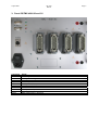
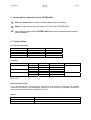
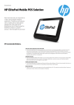
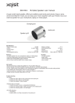
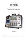
CS – 4001/127 TMC – 4001/63 Capacity Test Equipment Manual G. Jost – electronic . Larstr. 55 . 53844 Troisdorf . Germany . www.battery-testing.com August 2006 CS–4001 Manual Page 2 CONTENT 1. 2. 3. 4. 5. 6. 7. 8. Safety precautions........................................................................................... 3 Panel CS-4001/127 ........................................................................................... 4 Panel CS/TMC-4001/63 and /31....................................................................... 5 Connection of the battery to CS/TMC-4001 ................................................... 6 Removing the connections from CS/TMC-4001 ............................................ 7 Technical Data ................................................................................................. 7 Trouble shooting ............................................................................................. 8 The new DISPLAY PANEL............................................................................... 9 We reserve the right to make alterations and changes in the said system and to make changes in the information included in this manual without notice. We do not accept responsibility for damages of any type occurring in the use of the test system and/or occurring due to the fact that employment purposes could not be performed. The manufacturer can, in no case, be held responsible for direct damages, indirect damages or subsequent damages which occur to the customer by employment or non-employment possibilities of the product. © Copyright – 2006, G. Jost – electronic, DE- Troisdorf. All Rights reserved. August 2006 CS–4001 Manual Page 3 1. Safety precautions Before you begin to deal more deeply with the device itself we would like to give you a few safety hints in advance. Please observe the respective DIN/VDE/EN/IEC/ANSI-guidelines, the rules and regulations for local operators and the instructions of the battery manufacturer. While preparing and performing a discharge/capacity test it may happen under certain circumstances that a cell/block can explode which can damage any equipment next to it and/or harm personnel. For that reason never run a discharge test unattended. Which means in return never run the discharge test equipment such as CS/TMC-4001, load units etc. unattended. Battery systems are electrical equipment systems having high short-circuit currents. Avoid short-circuits which can cause current interruption, damage to the battery, station equipment and/or harm to personnel. Be sure to think about possible short-circuit dangers which can be caused by incorrectly connected shunts! Electrical conducting parts (Poles, Connectors, etc.) are only allowed to be touched with safety voltage probes or safety connection clamps. The CS/TMC-4001, the safety measuring leads and the accessories should only be employed for those purposes described here. Incorrect use can cause damage to the measuring system. Damage or used components must be immediately replaced. Do not use force in plugging the components together. CS/TMC4001 must only be connected to the, on the unit stated, mains voltage and frequency. Data transfer and output may only take place using the data transfer cable included in the delivery. Please be sure that you do not use data-cables from older versions of the TMC. The use of connection cables originating from other manufactures can lead to destruction of the measuring device, as well as, the follow-up data device. The device should not be exposed to direct sunshine or temperatures exceeding 45 degrees Celsius (e.g. laying onto heating units, radiators, etc.). August 2006 CS–4001 Manual 2. Panel CS-4001/127 Connector C1 – C8 U1 I1 T1 U2 I2 T2 SER AUX LED Red Yellow Green Usage Measuring leads, Multi-cable Battery 1, total voltage Battery 1, current Temperature sensor 1 Battery 2, total voltage Battery 2, current Temperature sensor 2 Serial port to PC Serial port to TORKEL LED indication Unit is powered up Unit measures Data transmission in progress Page 4 August 2006 CS–4001 Manual 3. Panel CS/TMC-4001/63 and /31 Connector C1 – C4 U I ALARM SER 1 SER 2 LED Red Yellow Green Usage Measuring leads, Multi-cable Battery, total voltage Battery, current Alarm output contact Serial port to PC Serial port to TORKEL LED indication Unit is powered up Unit measures Data transmission in progress Page 5 August 2006 CS–4001 Manual Page 6 4. Connection of the battery to CS/TMC-4001 Attention! The measuring cables must be connected to the TMC-4001 first, BEFORE being connected to the battery! 1) Power-up the CS/TMC-4001 and start the TMC95 or TMC4001-Light Software on your computer. 2) Connect the first measuring cable (multi-cable) to the connector C1 of the CS/TMC-4001. 3) Take the first crocodile–clamp (labelled with “1”) and connect it to the electrical minus pole of the battery. Continue connecting the remaining clamps in ascending order of numbering (from low voltage to high voltage) to the plus pole of each cell. If you need more than one multi-cable, connect them analogue to the first cable to the connectors C2 to C8 (TMC4001/63 to C4). 4) Connect the shunt voltage cable to the I-connectors of the TMC4001 (I1-connectors on CS-4001/127). Observe the correct polarity! 5) Connect the total voltage cable to the U-connectors of the TMC4001 (U1-connectors on CS-4001/127). If you are using a temperature sensor connect it to the T-connector (T1 on CS-4001/127). Test of two batteries in parallel When testing two batteries in parallel (CS-4001/127 only) proceed as follows: Connect the first battery to the connectors C1 to C4, but not more than 62 cells. Connect the second battery to the connectors C5 to C8. Connect the shunt voltage cables and the total voltage cables to the specific connectors (I1, U1 and T1 = batterie1; I2, U2 and T2 = battery2) on the TMC4001. 6) Connect the SER-connector of the CS/TMC-4001 to the serial port of your computer. When you are using a TORKEL for testing connect it to the AUX–connector of the CS/TMC-4001. 7) Start the capacity test from the software. August 2006 CS–4001 Manual Page 7 5. Removing the connections from CS/TMC-4001 First you must disconnect all crocodile-clamps from the battery. Next you can remove the connections C1 to C8 from CS/TMC-4001. You must not switch off the CS/TMC-4001 before all connections are removed from the battery. 6. Technical Data No. of measuring inputs Cell/Block voltage Total voltage Current Temperature CS-4001/127 127 2 2 2 TMC-4001/63 63 1 1 none Accuracy Input Cell/Block voltage Total voltage Current (shunt-voltage) Range DC 3V 15V 75V 600V 60mV 1000mV Resolution 1,00 mV 1,00 mV 10,0 mV 100 mV 0,01 mV 0,10 mV Accuracy ±0,05% ±2 Digits ±0,05% ±2 Digits ±0,10% ±2 Digits ±0,10% ±2 Digits ±0,10% ±2 Digits ±0,10% ±2 Digits Input impedance ≥ 1 MΩ ≥ 900 kΩ 600V CAT II Measuring multi-cables If not otherwise specified (when ordering), CS/TMC-4001 instruments are equipped with standard measuring multi-cables (Type MKB16/250) specified for 250V. Measuring multi-cables specified for 500 V (Type MKB16/500) are also available on request. Others Mains supply Operating temperature Storage temperature 85-264V~, 47-63Hz +10°C – 35°C +5°C – 50°C August 2006 CS–4001 Manual Page 8 7. Trouble shooting You may have the USB-cable connected to the device, before the CS-4001 has been powered up. Remove the USB-cable and power up the CS-4001 again. You have MISCONNECTED the battery to All measuring cables are connected, but CS/TMC4001. Make sure that the first measuring when scanning only about –0.100V or cable (Connector C1) is ALWAYS connected to the negative voltages are displayed. electrical minus pole of the battery. In the test data you’ve entered wrong limits for the All measuring cables are connected, but cell voltage. CS/TMC4001 has two cell voltage when scanning only voltages about 3,1V ranges: 3V and 15V which are automatically set are displayed, though higher voltage is according to the entered limits. applied. All voltages are displayed correctly, but the In the test data you’ve entered a wrong cell number direction (+ to -) or (- to +). Correct this setting order of the cells in the matrix is upside BEFORE the final measurement. down. All voltages values are correct, but they are In the test data you’ve entered wrong limits for the cell voltage. Please check and correct if necessary. all displayed in red colour. The total voltage cables are connected, but In the test data you’ve entered wrong limits for the total voltage. CS/TMC4001 has two total voltage when scanning only voltage about 78V is displayed, though higher voltage is applied. ranges: 75V and 600V which are automatically set according to the entered limits. In the test data you’ve entered a wrong shunt values. The shunt–cables are connected, but too CS/TMC4001 has two ranges : 60mV and 1000mV less current is displayed. which are automatically set according to the entered limits. The mV-value is responsible for the range setting. F. e. do enter 10A/10mV for shunt voltages up to 60mV, or do enter 100A/100mV (1000A/1000mV) for shunt voltages greater than 60mV. One measuring wire has no contact to the battery Two cell voltages are not measured – only connector or the corresponding fuse is blown. values about 0V are displayed. Please check that wire and it’s fuse. The display does not show the “START WINDOW” after power up. August 2006 CS–4001 Manual 8. The new DISPLAY PANEL The CS-4001/127 is equipped with our new LINUX board with TFT-Display and advanced communication facilities. The menu functions can be selected by turning the rotary button. The selected function is activated by pushing down the rotary button. The full function of this user interface will be implemented with our new CS-Manager software, which will be available around October 2006. Please use at the moment the “REMOTE SERIAL” function under: START MEASUREMENT -> STAND ALONE -> REMOTE SERIAL Page 9