1
FPC900r
User Manual
1
VARICURVE
S Y S T E M
V2.0
TM
DEP
11 August 1997
This equipment has been tested and found to comply with the following European Standards
for Electromagnetic Compatibility:
Emission Specification:
EN55013
(1990)
(Associated equipment)
Immunity Specification:
EN50082/1
(1992)
(RF Immunity, Fast Transients and
ESD)
Mains Disturbance:
EN61000/3/2
(1995)
For continued compliance ensure that all input and output cables are wired with cable screen
connected to Pin 1 of the XLR. The input XLR Pin 1 on BSS equipment is generally connected to
chassis via a capacitor to prevent ground loops whilst ensuring good EMC compatibility.
We have written this manual with the aim of helping installers, sound engineers and consultants to
get to grips with the FPR-900r and obtain its maximum capability.
If you are new to BSS products, we recommend that you begin at the start of the manual. If, however, you are already familiar with the intended application, and just want to get the unit installed
without delay, then follow the highlighted sections.
We welcome any comments or questions regarding the FPR-900r or other BSS products, and you
may contact us at the address or World Wide Web site given in the warranty section.
2
Quick Reference
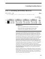
Quick Start - Quick Reference
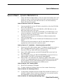
1
Check the Mains Voltage setting on the rear of the 900i Interface Unit and
install into a rack. Connect the mains to the 900i and check that the unit
powers up. All the front panel leds will flash on and off momentarily.
Switch off 900i mains power.
Refer to Sections 2.0 thru 2.6 'Installation'
2
Connect the Midi Out of the FPC-900i to the Midi In of the first FCS-926/
920 or FDS-388 device.
3
Connect the Midi Out of each FCS-926/920 or FDS-388 device to the
Midi Input of the next in the chain.
4
Connect the Midi Out of the last FCS-920/926 or FDS-388 device in the
chain to the Midi In of the FPC-900i Interface. This creates a Midi loop
through all of the Varicurve devices.
5
Change the Midi Channels on the devices to different numbers (their
order is unimportant).
6
Change the MIDI XMIT on all FCS-926 and FDS-388 devices to be MIDI
THRU.
7
Connect the FPC-900i Interface to the FPC-900r Remote using the
supplied 5pin XLR to 5pin XLR "umbilical cable".
Refer to Section 2.7 'Installation' - Data Connections and Midi.
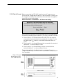
8
Power up the FPC-900i Interface again. The Remote should now come on
with a message detailing the version number of the installed software.
9
Press the UTILS key. Select XFER with the speed strip.
10 Select DATA AREA and turn the BOOST/PARAMETER control until the
box reads DUMP.
11 Select SOURCE and turn the BOOST/PARAMETER control until the box
reads ALLDEV. The DEST box should now read REMOTE.
12 Select START. The remote will ask “ARE YOU SURE?” Select YES to
continue. All program data from the FCS-920/926 devices will be copied
into the remote. (The FPC-900r Remote must be connected to the FPC900i Interface by the umbilical link for XFER to work.)
Refer to Section 15.0 'Transfer (XFER)'.
13
Exit UTILS by pressing UTILS again.
14 To select a device for editing, press one of the numeric Device keys.
Refer to Section 4.0 'Selecting a Device'
15
To adjust filter parameters press the Speed Strip beneath the frequency of
interest to assign a filter (or select an existing one). You can then use the
three parameter control knobs to adjust the filter.
Refer to Section 5.0 'Selecting and Adjusting Filters'
Please Read Overleaf...
3
VARICURVE
S Y S T E M
TM
Using This Manual
Please Read This! - Using This Manual
This manual has been written to make the understanding and
operation of the FPC-900 Remote as easy as possible. Because the
FPC-900 is a relatively sophisticated software product, we have
included several ways to find the information you require in this
manual, some of which are new. You will have already found a Quick
Reference on the previous page to get the user going from scratch.
These instructions are by no means all there is to know and references
are made to the main body of the manual for extra detail.
Table of Contents
The Contents now begins on Page 3, opposite this one. The chapter
and section names are generally those of the important Keys and
Controls on the Remote. This is a good place to find whole sections,
for example Events or Recall.
Quick Reference
Once you have found the appropriate chapter there is often a Quick
Reference section. This will give abbreviated instructions for the use of
the key or control. These can remind the user of a control’s operation
if the section has already been read.
"Refer to:"
Throughout the text there are references to other areas in the following
form.
Refer to Section 3.1 ‘Basic Controls’ - Display.
These will help to tie together different places where the same keys are
used for different purposes. They are also used heavily in Section 3.0
‘Basic Controls’....
"Section 3.0 Basic
Controls"
Section 3.0 has several drawings of front and rear panels of both the
remote and the Interface. Each are annotated and reference to the
appropriate letter will give a brief description of the item and usually a
reference to the section in the manual where the item is detailed at
greater length.
Index
Finally, when you need to refer to a particular feature quickly, the
Index may be the quickest way. The Index can be found at the end of
the manual, after the appendices.
Please feel free to give us your comments on this manual and any
ideas you may have for further improvement. Although we make every
effort to ensure that this manual is correct, there may have been recent
improvements made in the software which are not reflected in this
release.
4
Contents
Contents
1.0
2.0
2.1
2.2
2.3
2.4
2.5
2.6
2.7
2.8
2.9
3.0
3.1
3.2
3.3
3.4
4.0
4.1
4.2
4.3
5.0
5.1
5.2
5.3
5.4
5.5
5.6
5.7
5.8
5.9
5.10
Quick Start - Quick Reference
3
Please Read This! - Using This Manual
4
Table of Contents
Quick Reference
Index
"Refer to:"
"Section 3.0 Basic Controls"
4
4
4
4
4
Contents
5
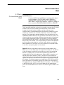
Introduction
7
Installation
8
Unpacking
Mechanical Requirements
Mains Power
Voltage Setting
Safety Earthing
AC Power Fusing
Data Connections and Midi
FSK
Internal Battery
8
8
9
10
10
10
11
13
14
Varicurve controls
16
Varicurve Display
Omnidrive Display
Remote Connections
Interface Controls and Connections
20
22
24
25
Selecting a Device
27
Device Keys
INDEX
SOLO
27
28
28
Selecting and Adjusting Filters
29
Using the Speed Strip.
Status bar boxes.
EQ Display
Speed Strip selection.
Filter adjustment.
Make-up gain
FLAT
EQ Bypass
Examining with VIEW
Scrolling the display
29
29
30
30
30
31
31
31
31
32
5
VARICURVE
S Y S T E M
TM
Contents
6.0
STORE
33
6.1
6.2
Naming Programs
INDEX in Store mode
34
34
RECALL
35
7.1
7.2
INDEX in Recall mode.
Recalling Between Devices
35
35
COMPARE
36
8.1
8.2
RECALL in Compare mode
INDEX in Compare mode
WARNING!
36
37
37
Utilities Menu
38
UTILS
Action of Utilities
MORE sub-menu
38
39
41
Grouping - GROUP and ALL
42
GROUP
Group UTILS
Group ALL
42
43
44
RTA (Real Time Analyser)
45
RTA Menu
RTA memories
Storing an RTA
Recalling An RTA
45
47
47
47
Room Curve and Add Curve
48
Room Curves
ROOMCV
ADD Curve
48
48
49
AUTO EQ
50
13.1
13.2
13.3
A simple AUTO EQ
Mixed RTA Sources.
Target Room Curves
50
51
52
EVENT
53
14.1
14.2
14.3
14.4
Event Edit Screen
Event Select Menu
Triggering Events
INDEX with Events.
53
55
55
56
Transfer (XFER)
57
XFER Menu
57
16.0
Smart Card
59
16.1
16.2
CARD Menu
Card Types
59
62
7.0
8.0
9.0
9.1
9.2
9.3
10.0
10.1
10.2
10.3
11.0
11.1
11.2
11.3
11.4
12.0
12.1
12.2
12.3
13.0
14.0
15.0
15.1
6
Introduction
17.0
Controlling Omnidrive Devices
63
18.0
Controlling Delay Devices
65
19.0
Warranty Information
67
20.0
Appendix
68
Transient Suppressor Replacement
Microphone stand adapter
FPC-900 Midi Implementation
Frequency Weighting Characteristics
68
68
69
70
Index
71
User notes
74
20.1
20.2
20.3
20.4
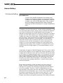
1.0
Introduction
The FPC-900 is a portable, wireless remote controller for the FCS-926
and FCS-920 Varicurve Equaliser units and the FDS-388 Omnidrive PA
controller. It offers sound engineers and contractors unparalleled
flexibility and efficiency in the calibration and control of distributed
array systems, and programmable multiband parametric EQ for up to
32 audio channels.
Communicating via a supplied multiway cable, a standard radio-mic
link or an XLR tie line, the FPC-900 allows the operator to address a
network of up to 16 FCS-926/920 Dual VARICURVE Equaliser
Analyser units and FDS-388 Omnidrive PA controller and crossover
units from anywhere in an arena, stadium or installation venue.
The intuitive control surface provides familiar rotary control of EQ and
RTA parameters in real time with instant selection of functions via a
unique Speed Strip touch pad.
The FPC-900 can control all of the features of the VARICURVE units
and, in addition, can Group several VARICURVE units to be controlled
simultaneously.
The FPC-900 can control the gain, mute and delay variables within an
FDS-388 Omnidrive controller.
For show time, an Events system can command user-defined
sequences of Midi program changes mapped to VARICURVE
Equalisers or other non-BSS Midi controlled equipment such as effects
processors and routing matrices.
7
VARICURVE
S Y S T E M
TM
Installation
2.0
Installation
2.1 Unpacking
As part of BSS Audio’s policy of quality control, this product is
carefully checked before packing to ensure flawless appearance and
that it reaches you in first class condition.
After unpacking the two units, please inspect them for any physical
damage. If any damage has occurred, notify your dealer immediately.
A written claim for damages can then be initiated. The Warranty at the
end of the manual gives more information (see section 18.0).
Please retain the shipping carton and all the packing materials for use
should the unit need to be transported or returned for any reason.
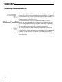
2.2 Mechanical
Requirements
The FPC-900i interface requires a vertical rack space of 1U (1.75" or
44mm). The unit should be supported at its rear by additional bracing
or shelving if it is to be used in a transportable system. Failure to do so
will impair the reliability and may possibly invalidate the warranty.
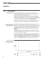
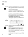
Figure 2.1 details the relevant dimensions and fixing centres for the
FPC-900i.
Adequate ventilation must be provided by allowing sufficient space
around the sides and rear of the FPC-900i to ensure free circulation of
air. Forced cooling is not required.
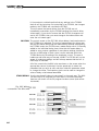
The FPC-900r remote is intended to be portable and has no particular
mechanical requirements. Care should be taken to ensure that the
remote is properly cushioned in transit. The unit should be kept in the
carry case provided and transported securely to prevent movement and
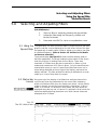
heavy impacts. Figure 2.2 details the overall size of the FPC-900r.
Fig 2.1 Overall
dimensions of the
FPC-900i Interface
8
2.3 Mains Power
Before connecting the FPC-900i interface to an AC power source,
check that the voltage selector switch on the side panel is correctly set.
If a change is necessary then ensure that the mains fuse is changed for
one of the correct current rating
Refer to Section 2.6 'Installation' - AC Power and Fusing.
WARNING! THIS APPLIANCE MUST BE EARTHED.
IMPORTANT: The wires in the mains lead are colour coded in
accordance with the following code.
Green and Yellow......Earth
Blue......Neutral
Brown......Live
As the colours of the wires in the mains lead may not correspond with
the markings identifying the terminals in your plug, proceed as follows.
! The wire which is coloured Green and Yellow or Green must be
connected to the terminal which is marked with the letter ‘E’ or by
the Earth signal
or which is coloured Green and Yellow or
Green.
" The wire which is coloured Blue must be connected to the terminal
labelled ‘N’ or coloured Black or Blue.
# The wire which is coloured Brown must be connected to the
terminal labelled ‘L’ or coloured Red or Brown.
Those units supplied to the North American market will have an
integral moulded 3 pin connector which is provided to satisfy required
local standards.
Fig 2.2 Overall
dimensions of the
FPC-900r Remote
9
VARICURVE
S Y S T E M
TM
Voltage Setting
Safety Earthing
AC Power Fusing
2.4 Voltage Setting
The mains voltage selector switch provides a simple external adjustment to allow operation on all international AC power standards.
Newer units are supplied with 115/230V selector switches. The allowable ranges for the supply voltage are:
90VAC up to 132VAC on the 120V or 115V position and
190VAC up to 264VAC on the 240V or 230V position.
Outside these voltages the unit will not work satisfactorily, if at all.
Voltages in excess of the maximum will probably cause damage.
Voltages below the minimum will cause the power supplies to drop out
of regulation, degrading the performance of the system. The battery
pack in the remote will preserve all data in the event of a power failure.
2.5 Safety Earthing
The Green and Yellow wire of the mains cord must always be connected to an installation Safety Earth or Ground. It is essential for personal safety as well as the correct operation of the system, and is internally connected to all exposed metal surfaces. Any rack framework into
which this unit may be mounted is assumed to be connected to the
same grounding circuit.
2.6 AC Power
Fusing
The incoming mains power is fused within the FPC-900i by the fuse
holder mounted on the rear panel. Should it be necessary, the fuse must
be replaced by one of the same size and current rating.
20mm T200mA for the 240V o r 230V setting
20mm T315mA for the 120V or 115V setting
It is most important for continued safety that this specification is strictly
adhered to. Spare fuses of the correct rating are supplied with the unit
from new.
It is unlikely that the AC fuse will fail during normal use and caution
should be exercised if it does. The most likely reason at first power up is
the incorrect setting of the mains voltage switch on the side panel.
Another reason may be the connection of the unit across two lines of a
three phase supply. In both of these cases the internal transient suppressors may have been damaged and will continue to blow replacement
fuses, even if the supply is now correct. The suppressors will have
protected the FPC-900i from damage and need replacing before the
interface can be used again. Refer to section 19.1 for the replacement
procedure.
10
Data Connections
Midi
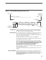
2.7 Data
Connections and
Midi
Quick Reference
Connect MIDI Outs to MIDI Ins in a daisy chain back
to the Interface. Set FCS-926s and FCS-920s to
different MIDI channels, and set FCS-926s to MIDI
XMIT THRU. Connect the Remote - Interface umbilical
then execute UTILS/XFER/DUMP ALLDEV to REMOTE.
The 5-way XLR umbilical cable which normally connects the FPC-900r
remote to the FPC-900i interface provides power for the remote,
charges the internal lead-acid battery, and provides two-way
communication. Data emanating from the remote is passed on by the
interface to the MIDI Out socket for distribution to the various BSS
devices. The remote also requests data back from the devices so that
updated parameter values can be checked to eliminate the chance of a
communications error causing a difference between what is displayed
on the remote, and what is active on the device. For this to happen,
the remote must be able to talk to any device, and any device must be
able to talk to the remote. This is achieved by the Varicurve equalisers
and Omnidrives operating in a ‘soft thru’ mode, where any received
data is passed on to the MIDI Out, but if the device is required to talk,
it can do so by injecting data into the stream.
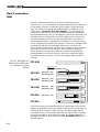
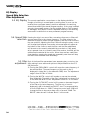
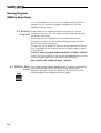
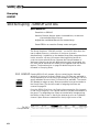
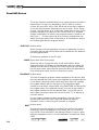
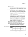
Figure 2.3 shows how multiple units should connect together on a
MIDI loop. Connect MIDI Out of the FPC-900i Interface to the MIDI In
of the first device, then MIDI Out to MIDI In etc to all the remaining
devices in a daisy chain. Connect the final MIDI Out back to the
Interface MIDI In. Set all the devices to different MIDI channels, and
set their MIDI XMIT mode to THRU. Connect the 5-way umbilical
cable between the remote and interface. When power is applied to the
system, the display of the remote will energise, and a startup message
will appear. If a meteorology probe is used on an FDS-388 Omnidrive
then it should be connected to the first FDS-388 in the loop after the
FPC-900i MIDI Out. Set the METEOROLOGY variable on the FDS-388
to METEOROLOGY AUTO on the unit fitted with the meteorology
probe and to METEOROLOGY MIDI on the following FDS-388s on the
loop.
11
VARICURVE
S Y S T E M
TM
Data Connections
Midi
Since the remote stores within it all data concerned with each
Varicurve unit, it is first essential to dump all data from the Varicurves
to the remote. Data for Omnidrives is only stored in the Omnidrive
itself. To initiate this process, use XFER ALLDEV to REMOTE in the
UTILS menu - see section 15.0 'Xfer (transfer)'. This must be done
whenever any device in the system is added, removed or adjusted in
any fundamental way, such as changing the channel access mode. The
automatic device polling which occurs invisibly to the user collects
current parameters from the currently selected device, but does not
collect program data or configuration information, so the user should
not be complacent and expect the remote to follow any changes made
to the device without its knowledge. Rather, the controls on the
Varicurve devices should be left alone once a dump is done, and then
use only the controls on the remote to alter the device settings. In
‘panic’ situations though, the system will tolerate filter parameters
being adjusted on the device controls, which the remote will get to
know about on the next poll, which occurs approximately every 10
seconds.
Fig 2.3 FDS 388, FCS
920 and FCS 926 used
in a Remote Control
System
IN
FPC-900i
OUT
Meteorology Probe
IN
FDS-388
MIDI Xmit
FDS-388
MIDI Xmit
FDS-388
MIDI Xmit
FCS-926
MIDI Mode
Thru
Meteorology Auto
Thru
Meteorology Midi
Thru
Meteorology Midi
OUT
IN
OUT
IN
OUT
IN
FCS-920
Thru
OUT
IN
OUT
Up to three series-connected 6m umbilical cables may be connected
together to extend the radius of operation before power losses become
a problem. With a heavier cable however, the cable length may be
increased. A four-core screened cable with 0.5 square mm conductors
will allow a length of up to 50m to be used. If a greater distance is
required, then use the FSK communications (see section 2.8) and the
internal battery.
12
FSK
2.8 FSK
An FSK (Frequency Shift Keying) communications channel is included
for operation over long microphone cables, or over a standard
musicians wireless link. One-way data transmission is then possible,
although the user may notice that the lower data rate results in slower
reaction of the devices to commands issued by the remote.
Using standard microphone XLR cable, lengths of several hundred
metres are quite acceptable. A wireless link however allows not only a
greater operating range, but also more freedom since it is not necessary
to drag cables around. The signal level from the remote is around
0dBu, compatible with the guitar input of a wireless transmitter. The
FSK input of the interface will accept a similar signal level, although
any signal level which lights the SIG LED, but does not light the PEAK
LED will be acceptable. If this is not the case, then adjust the signal
level from the receiver to suit. If the ERROR LED lights, then the signal
may be too noisy or intermittent.
13
VARICURVE
S Y S T E M
TM
Internal Battery
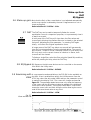
2.9 Internal Battery
Quick Reference
Connect the umbilical between the remote and
interface so that the charger can keep the battery
charged. Any flashing LEDs on the interface indicate
charge to go. All four LEDs light when fully charged.
Keep the display brightness lower when working
remotely via FSK, and always re-charge immediately
after.
The battery in the FPC-900r remote is a lead-acid type designed for long
life, when subjected to proper charge cycling. Unlike Nickel-cadmium
cells, lead-acid batteries will tolerate frequent light discharges. The
shallower the discharge, the more the life will be improved. The battery
charger in the FPC-900i interface is an intelligent processor controlled
charger which takes care of the battery charge management transparently to the user. Leave the umbilical connected to the energised Interface all the time the remote is in use if possible. Only disconnect it
when FSK communication is essential, and then only for as long as
necessary. As soon as FSK is finished with, put the remote back on
charge. You cannot overcharge the battery since the interface stops
charging when the battery is fully charged. The CHARGE LEDs on the
interface show the charge progress. On an exhausted battery, all four
will flash.
As the battery charges, the CHARGE bargraph will ‘fill-up’ with lit LEDs,
while the top ones flash to show charge to go. When the battery is fully
charged, all four LEDs will be on and none will flash. Whilst connected
to the interface, the battery bargraph meter on the remote will show the
same charge progress as the interface. When the remote is working on
battery power, the battery meter shows life remaining, which are not
the same. If the FAULT LED should light on the interface, then this
could indicate either a battery malfunction, or that the fuse inside the
remote has ruptured.
When working remotely via FSK, the battery is the only source of
power. The main consumer of power in the remote is the display
backlight, so to preserve life, the display brightness should be kept as
low as is acceptable. Typically, a freshly charged battery will give
approximately 40 minutes of use when the display is at full brightness,
whereas at minimum brightness, up to 3 hours can be expected. When
the remote is powered from the interface via the umbilical, it is energised continuously, and does not switch off. Under battery power
however, the remote is energised by pressing the ON button momentar14
Internal Battery
ily. The unit will remain energised for approximately 30 seconds after
which it will switch off automatically, unless a control is moved, which
starts the timer for another 30 seconds.
As time progresses, the battery meter will gradually empty, until ultimately, unless the user recharges the battery, the meter will empty,
soon after which the display brightness will automatically dim to conserve power, and ultimately the unit will switch itself off so that sufficient charge is retained to keep the internal memory energised.
Never leave the battery in a discharged condition for long periods
otherwise the memory contents may be lost, and the battery may suffer
irreversible damage. As soon as possible, re-charge the battery. If the
remote is to be stored for an extended period, make sure that the battery
is fully charged.
15
VARICURVE
S Y S T E M
TM
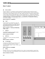
Basic Controls
A
NUMERIC KEYS
The NUMERIC KEYS have two independent modes, switching automatically as required by the
current mode of the Remote.
1 As ‘Channel keys’ to select a device or several devices for display and editing.
Refer to Section 4.0 ‘Selecting a Device’, Section 4.3 ‘SOLO’ and Section 10.0 ‘Grouping’ GROUP and ALL.
2 As ‘Alphanumeric keys’ for entering text when storing programs or naming devices and events.
Refer to Section 6.1 ‘STORE’ - Naming Programs and Section 14.4 ‘Events’ - Index with Events.
B
SPEED STRIP
The Speed Strip is a linear controller which
allows the user to select filters and menu items
with finger presses. Its mode of operation
varies with screen mode.
1 When the display is scrolled down, showing the top status bar and an EQ curve, the
Speed Strip will select between filters. The
chosen filter is denoted by a vertical cursor
of dots.
Refer to Section 5.1 ‘Selecting and Adjusting Filters’ - Speed Strip
2 When the display is scrolled up, showing a
selection menu along the bottom edge of
the screen, the Speed Strip will select
between the menu items available.
Refer to Section 9.0 ‘Utilities’
C
GROUP and ALL
The GROUP key allows several devices (or
their individual audio channels) to be combined and adjusted simultaneously. Controls
available to the group include group muting
and bypass in addition to the standard filter
controls. The ALL key works in conjunction
with the Grouping system to put all available devices into a group.
Refer to Section 10.0 ‘Grouping’ - GROUP and ALL
16
D
SOLO
SOLO allows the user to listen to individual devices or audio channels. Several channels can be
selected to be heard simultaneously - all unselected devices and audio channels are muted.
Refer to Section 4.3 ‘Selecting a Device’ - SOLO
E
EVENT
The EVENT system allows the user to trigger combinations of program changes across all linked
Midi devices with a single command. A maximum of 50 Events are available in the FPC900r each
of which can be programmed with a different program change for each Midi device.
The FPC900r Event system will send program changes to any equipment connected
by Midi and so can be used for the control of
any Midi equipment whether or not manufactured by BSS. Events can be triggered
from the Speed Strip or the Event key in the
Event Select menu.
Refer to Section 14.0 ‘Events’.
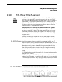
F INDEX
The INDEX key will list index information
related to the current display.
1 Selecting INDEX while in normal filter
adjust mode will provide a display of devices
along with their user defined names. The
names can be edited and a new device
selected from here.
Refer to Section 4.0 ‘Selecting a Device’
2 Selecting INDEX whilst storing, recalling
or comparing programs will display a list of
all programs available on the current device.
Refer to Section 6.2 ‘STORE’ - INDEX in Store mode.
Refer to Section 7.1 ‘RECALL’ - INDEX in Recall mode.
3 Pressing INDEX whilst in the Event Select menu will display a list of all Events available with
their names.
Refer to Section 14.0 ‘EVENT’
17
VARICURVE
S Y S T E M
TM
Basic Controls
G
ON/CHECK
When the Remote is connected to the Rack Interface (FPC-900i) through the umbilical cable it
should be turned on and off at the Rack Interface unit using the Mains switch. When the Remote is
powered by its internal battery it will go into ‘sleep’ mode 30 seconds or so after the last key press or
control change. Press the ON/CHECK switch to turn the Remote back on. Pressing the ON/CHECK
while the remote is powered up will cause all the connected Varicurve equalisers to flash a response
message ("Receiving.." on FCS-926 and FDS-388, "...." on FCS-920). This gives a fast method of
checking the integrity of midi connections. If the communications link is complete the remote will
also show the message "****RECEIVING*****".
Refer to Section 2.0 'Installation'.
H
FLAT
Press the FLAT key momentarily to hear the
chosen audio channel with no equalisation. A
second press returns the previous EQ. Pressing
and holding the FLAT key will permanently
flatten the chosen channel.
Refer to Section 5.7 ‘Selecting and Adjusting
Filters’ - FLAT.
I
STORE
Use STORE to save the current EQ program
along with a user defined name.
Refer to Section 6.0 ‘STORE'.
J
RECALL
Use RECALL to recall a previously stored EQ
program.
Refer to Section 7.0 ‘RECALL'.
K
COMPARE
Pressing the COMPARE key will allow the user
to browse through the stored EQ programs
hearing the effect of each, in turn, on the current
audio channel.
Refer to Section 8.0 ‘COMPARE'.
L
UTILS
Pressing UTILS will scroll the display upwards to show a menu of set-up and device control items.
The items are selected using the Speed Strip and then adjusted with the BOOST/PARAMETER control.
Refer to Section 9.0 ‘Utilities’
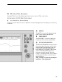
18
M
RTA (Real Time Analyser)
Pressing RTA will scroll the display upwards to show a menu of RTA control items.
Refer to Section 11.0 ‘RTA (Real Time Analyser)’
N
CONTRAST & BRIGHTNESS
These two controls allow the user to adjust the contrast and brightness of the display to suit viewing
conditions.
O
WIDTH
The WIDTH control will adjust the bandwidth of the currently selected filter.
P
FREQUENCY
The FREQUENCY control will adjust the
frequency of the currently selected filter.
Q
BOOST/PARAMETER
The BOOST/PARAMETER control is primarily used to adjust the boost and cut value
of the currently selected filter. When the
UTILS or RTA menus are displayed or
when data entry is required on the screen,
the BOOST/PARAMETER adjustment
becomes a general purpose data entry
control. Turning the control will increment
and decrement a value or step through a
series of options.
Refer to Section 5.5 ‘Selecting and Adjusting Filters’ - Filter Adjustment
19
VARICURVE
S Y S T E M
TM
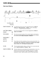
Varicurve Display
3.1 Varicurve
Display
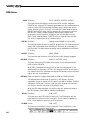
A
User-defined name for each of the 16 available devices. Refer to
Section 4.2 'Selecting a device' - INDEX. This box will display
"--GROUP--" when Group mode is selected.
LAST TRIGGERED
EVENT
B
This is the name and number of the last triggered Event. Refer to
Section 14.0 'EVENT'.
DEVICE NAME
PROGRAM
C
FREQUENCY
D
WIDTH
E
BOOST
F
These display the filter parameters of the currently selected filter. The
upper value is for channel 1 in a dual device, the lower is for channel
2. In Stereo, both are displayed; in Mono on the upper value is used.
Refer to Section 5.0 'Selecting and Adjusting Filters'.
GAIN
G
This box displays the gain value, or values, for the currently selected
device. Refer to Section 9.2 'Utilities' - Gain.
DEVICE STATUS
H
This box displays the current status of the selected device. It will only
display the most important status message at any time. In order of
priority, from most important to least, the messages are; LOCKED,
SHOWTM, GROUP, VIEW, BYPASS, MUTED, PKFIX and MONO.
20
This is the name and number of the current program on this device.
The program number will shrink in size if the program has changed
since it was recalled. Refer to Section 7.0 'RECALL'.
BATTERY
I
This box gives a graphical representation of the battery charge
available if the remote is being operated using its internal battery. See
Section 2.9 'Installation' - Internal Battery.
dB SCALE
J
This vertical scale displays the cut and boost values for the
equalisation contour across the centre of the screen. The whole screen
can be shifted up or down to see peaks or notches using the VSCROL
utility. Refer to Section 9.2 'Utilities' - VSCROL.
ON-SCREEN HELP
K
There are two display lines devoted to on-screen help. When the
upper status bar in on the screen, the help text will appear in the line
below the status bar. If one of the lower menus is in use, the help text
will appear just above the menu. The help text will change to
represent the current screen or item selected. The help text details the
most important options available from the current position.
FILTERS AVAILABLE
L
This is the number of filters available in the currently selected device.
Usable filters are those which have a cut or boost value of 0dB. If a
filter has its cut/boost reduced to 0dB, its marker will disappear and
the Filters Available value will increase by one. Available filters can be
positioned by touching the Speed Strip at the required frequency
position and adjusting the cut/boost control.
CURSOR
EQUALISATION
CURVE
M
N
FREQUENCY SCALE
O
FILTER MARKER
The cursor represents the current filter's Frequency position. Selecting
VIEW ON Refer to Section 9.2 'Utilities' - VIEW will change the
cursor and allow the user to move the cursor along the display
checking the cut/boost value of the curve or curves at each of the 210
frequency points.
The curve, or curves, across the screen are a precise graphical
representation of the frequency response of the current Varicurve
device.
The dot marks across the bottom of the EQ display represent the 30
frequencies labelled on the speed strip. These are the frequencies used
in the Real Time Analyser display. Refer to Section 11.0 'RTA'.
Q
Each of the triangular markers represents a filter that has a cut or boost
value associated with it. These filters can be selected for adjustment by
touching the Speed Strip at the marker position. Refer to Section 5.1
'Selecting and Adjusting Filters' - Using the Speed Strip.
21
VARICURVE
S Y S T E M
TM
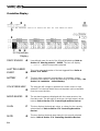
Omnidrive Display
3.2 Omnidrive
Display
A
User-defined name for each of the 16 available devices. Refer to
Section 4.2 'Selecting a device' - INDEX. This box will display
"--GROUP--" when Group mode is selected.
LAST TRIGGERED
EVENT
B
This is the name and number of the last triggered Event. Refer to
Section 14.0 'EVENT'.
DEVICE NAME
BATTERY
C
This box gives a graphical representation of the battery charge
available if the remote is being operated using its internal battery. See
Section 2.9 'Installation' - Internal Battery.
ON-SCREEN HELP
D
The help text will change to represent the current screen or item
selected. The help text details the most important options available
from the current position.
BAND NAMES
E
The two band names are displayed with the names as set on the
Omnidrive unit. The left name is at the top, the right name is at the
bottom. Refer to Section 17.0 'Controlling Omnidrive Devices'.
GAIN
F
This box displays the band gain value, or values, for the currently
selected device. Refer to Section 17.0 'Controlling Omnidrive
Devices'.
MUTE
G
This box displays the band mute status for the currently selected
device. Refer to Section 17.0 'Controlling Omnidrive Devices'.
22
DELAY
H
This box displays the band delay value, or values, for the currently
selected device. Refer to Section 17.0 'Controlling Omnidrive
Devices'.
MAIN DELAY
I
This box displays the main delay value, or values, for the currently
selected device. Refer to Section 17.0 'Controlling Omnidrive
Devices'.
UNITS
J
This box displays the local delay units for the currently selected
device. This is not the same units as on the device itself. Refer to
Section 17.0 'Controlling Omnidrive Devices'.
23
VARICURVE
S Y S T E M
TM
Remote Connections
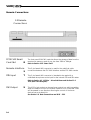
3.3 Remote
Connections
PCMCIA2 Smart
Card Slot
R
The front panel PCMCIA2 card slot allows the storage of data from the
remote onto memory cards of any size from 256k to 2Mbyte.
Refer to Section 16.0 'Smart Card'
Remote Interface
S
This 5 pin female XLR connector is used for the umbilical cable
connection between the FPC-900i interface and the FPC-900r remote.
RTA Input
T
This 3 pin female XLR connector is intended to be used with a
calibrated microphone as the input for the internal RTA and SPL meter.
Refer to Section 9.3 'Utilities' - More Sub-Menu and Section 11.0
'RTA (Real Time Analyser)'.
FSK Output
U
This 0.25in jack socket can be used as an output to a radio transmitter
when the umbilical link to the remote interface is not connected. Data
will be passed in one direction allowing the control of Varicurve
devices over a wireless link.
See Section 2.8 'Data Connections and Midi' - FSK.
24
Interface Controls and Connections
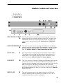
3.4 Interface
Controls and
Connections
N
PINK NOISE OUTPUT
A
The FPC-900i pink noise output can be turned on and off from the
remote. Press UTILS and select MORE or press RTA. The menu item
named PINK will turn the noise output on and off. The pink noise
output level is approximately +1dBu. See Section 9.3 'MORE Submenu'.
REMOTE INTERFACE
B
This 5 pin connector carries the power and data link to the Remote
using the supplied multicore cable. This connector is wired in parallel
with the connector labelled REMOTE INTERFACE on the rear panel
(See 'M'). Refer to Section 2.7 'Data Connections and Midi'.
FAULT LED
C
This led indicates a charging fault with the Remote internal battery.
The interface cannot charge the battery due to disconnection or a
battery fault. There is also a protection fuse on the battery circuit
within the Remote. Refer to Section 2.9 'Internal Battery'.
FSK INPUT
D
This 3 pin socket is a Frequency Shift Keying (FSK) data input from the
remote. This connector carries control data from the remote to the
interface through a standard audio cable or wireless link. Note that this
data is one way only. No data is returned from the controlled
Varicurve units to the remote. This connector is wired in parallel with
the connector labelled FSK INPUT on the rear panel (See 'L'). Refer to
Section 2.8 'FSK'.
ERROR LED
E
This led indicates an error in the data received on the FSK input.
Possible causes are loss of transmission if a radio link is in use, or
insufficient signal level, noise or interference.
25
VARICURVE
S Y S T E M
TM
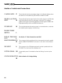
Interface Controls and Connections
CHARGE LEDS
F
These leds indicate the percentage charge in the Remote battery when
the remote is connected using the multicore umbilical cable.
SIGNAL and PEAK
LEDS
G
These leds indicate the signal level of the audio signal on the FSK data
input from either the front or rear panel connectors. The wireless
system receiver gain should be adjusted so that the green SIGNAL led
lights permanently but the red PEAK led does not.
POWER LED
H
This led indicates that the mains power is connected and on, and that
the interface power supply is functioning.
MAINS POWER
SWITCH
I
MIDI IN, THRU AND
OUT
J
REMOTE INTERFACE
K
See Section 2.7 'Data Connections and Midi'.
This connector for the multicore link to the remote is wired in parallel
with the REMOTE INTERFACE connector on the front of the interface
unit.
FSK INPUT
L
This connector is for FSK data input and is wired in parallel with the
FSK INPUT on the front of the interface unit.
OPTION PANEL
M
A removable panel is included to allow the fitting of control option
ports.
VOLTAGE SELECTOR
N
26
Refer to Section 2.4 Voltage Setting
Selecting a Device
Numeric Keys
4.0
Selecting a Device
Quick Reference
Press a Device key to select an individual device or channel.
Press both Device keys on the selected device to change a
device from Dual to Stereo, or from Stereo back to Dual.
4.1 Device Keys
The 16 pairs of Device keys on the left hand side of the Remote are
used to select between the devices connected to the system. The key
numbers - from 1 to 16 - relate directly to Midi Channel numbers.
Think of the Device keys as 'steering' the controls and display to any
device or channel.
If a Varicurve device is in Stereo or 12 band Mono mode, pressing
either of the Device keys will select that device. In Dual channel mode
each of the Device keys will select one of the two Varicurve channels
in a device. Refer to section 17.0 for information on controlling the
FDS-388 Omnidrive.
Note: Pressing a Device key will cause a Response message to be
displayed on any devices connected to that Midi channel.
Each Varicurve device can be changed between Mono, Dual and
Stereo modes from the remote.
Mono
Only the left hand channel led will be lit in Mono mode. Up to 12
filters are available for adjustment. The STATUS box at the top right of
the screen will show MONO unless a higher priority message is being
displayed. Switching a device to and from mono can only be done by
selecting the UTILITY menu and adjusting the MONO item. Refer to
Section 9.2 ‘Utilities’.
Dual and Stereo
In these modes each channel has six filters available. Dual mode
allows the two channels in a single device to be adjusted
independently of each other. Linking them in Stereo causes the filters
in each channel to track the corresponding filters in the other channel.
In Stereo, both channel curves are displayed together.
To switch between Dual and Stereo simultaneously press both of a
device’s Device keys. Both of the device channel leds will be lit in
Stereo mode.
27
VARICURVE
S Y S T E M
TM
INDEX
SOLO
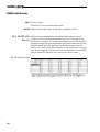
4.2 INDEX
Pressing the INDEX key displays a directory of all the device numbers.
Each entry corresponds to a Midi channel. The entry displays the type
of device connected to the Midi channel, which mode it is in and its
user defined name or names. To select a device to edit or to change its
user name either:
$ Press the corresponding Device Key or
$ Choose SELECT on the menu with the Speed Strip and turn the
parameter control to move the highlight cursor.
Pressing a device Device key when it is already highlighted will select
the device to be the current device.
To edit the selected device or channel name, choose NAME on the
menu and enter a new name using the Device keys. Each key will
enter the character printed next to it. To enter a character that is
printed within a square box press the Shift key (bottom left corner of
the Device keys) and then press the second Device key adjacent to the
required character. There is no Enter or Return key to finish - all
characters entered go straight into the device name.
To edit another name, choose SELECT on the Speed Strip and move to
another device by pressing its Device key.
Pressing INDEX a second time will leave the Index screen.
Fig. 4.1
Index screen
4.3 SOLO
SOLO allows one or more channels to be heard individually. Solo will
not work when viewing an Omnidrive device, nor can the user solo
an Omnidrive device
Pressing SOLO once will start the Solo led flashing. At this time no
muting will have taken place. If one of the Device keys is pressed, all
channels except the selected channel will be muted. Channels can
now be added to, or removed from, the solo selection by pressing their
Device keys. To leave Solo press the SOLO key again. All device
channels will return to their original mute status. The pattern of soloed
channels is NOT stored on leaving Solo. Returning to Solo will require
channels to be selected again.
Pressing GROUP while there are channels soloed will create a group
comprising the solo channels.
28
Refer to Section 10.0 ‘Grouping - GROUP and ALL’ for more details
on groups.
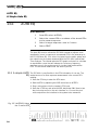
Selecting and Adjusting Filters
Using the Speed Strip
Status Bar Boxes
5.0
Selecting and Adjusting Filters
Quick Reference
5.1 Using the
Speed Strip.
1
Select a filter to adjust by pressing the Speed Strip.
2
Adjust the filter using the Frequency, Width and
Boost/Cut knobs.
3
Press and hold FLAT to clear an equalisation curve.
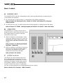
The speed strip is a linear controller used in conjunction with the filter
graphics and text menus displayed on the lcd screen. Most of the time
the speed strip is used to select a filter to adjust or to create a new filter
at a desired frequency. (Refer to Section 9.0 ‘Utilities’ to find details
on the menu selections.)
The screen display (See figure 5.1) shows the 900r display ready to
edit filter parameters. The arrow heads along the bottom of the screen
mark the positions of existing filters for this device. There are a
maximum of 6 filters when the device selected is in Stereo or Dual
modes and a maximum of 12 filters in Mono. Only the used filters are
marked with arrows, a count of spare filters (filters set to zero cut or
boost) being displayed at the top right of the display, just below the
battery indicator. The filter selected for editing is marked with a cursor
made up of a row of dots down the screen.
5.2 Status bar
boxes.
Along the top of the display in the Status bar are three boxes which
continuously show the parameters for the current filter; frequency,
width and cut/boost. Each box can display two values - the top values
relate to channel one and the lower values to channel two. In Mono
mode, or if channel 1 is selected in Dual mode, the filter values are
displayed along the top row. If channel 2 is selected in Dual mode, the
values are displayed along the bottom row. Both channel values are
displayed when in Stereo.
Fig. 5.1
The FPC-900r screen
29
VARICURVE
S Y S T E M
TM
EQ Display
Speed Strip Selection
Filter Adjustment
5.3 EQ Display
The current equalisation curve shown on the display should be
thought of as being in a scratchpad or working area. A curve can be
recalled from a program memory and then adjusted in the working
area without altering the stored program memory. If the curve is edited
wrongly, the program memory can be recalled again or FLAT pressed
to start again. Only when a curve is adjusted correctly in the working
area need it be stored into a more permanent program memory.
5.4 Speed Strip
selection.
Pressing the strip in an area of the curve where there are no filters will
move a spare filter to the chosen frequency. The filter values in the
status bar change to reflect the new frequency and the cursor moves to
the new position. Adjusting the filter Cut/boost using the rotary control
will change the displayed curve and a new arrowhead will appear at
the bottom of the cursor to mark the filter and the filter adjustment
will be sent to the currently selected Varicurve device. If the speed
strip is pressed close to a currently used filter marker, that filter will be
selected and marked with the cursor. When there are two used filters
close together, pressing the speed strip repeatedly near them will step
the filter cursor between them alternately.
5.5 Filter
adjustment.
Each of the three filter parameters has a separate rotary control on the
900r making it even easier and quicker to adjust filters than the FCS926 Varicurve.
$ Turning the FREQUENCY control will move the centre frequency of
the selected filter. The exact frequency of the peak or dip is
displayed in Hertz (Hz) in the status bar FREQ: box. The adjustment
range is from 20.7Hz to 20kHz.
$ Turning the WIDTH control will broaden or narrow the selected
filter bandwidth. The width of the filter is displayed in octaves (Oct)
in the status bar WIDTH: box. Adjustment is from 0.1 to 2 octaves.
$ Turning the CUT/BOOST control will increase or decrease the gain
of the filter at its centre frequency. The filter cut or boost is
displayed in dB in the status bar BOOST: box. The range available
is from +15dB down to -15dB. Turning the control past -15dB will
change the filter to become a deep notch of around -30dB. The
BOOST: status box will indicate ‘Notch’ in this mode.
30
Make-up Gain
FLAT
EQ Bypass
5.6 Make-up gain
Note that the Gain of the current device is not adjusted automatically
and so may need to be altered by the user if large amounts of cut or
boost are applied.
Refer to Section 9.2 ‘Utilities’ - Gain.
5.7 FLAT
The FLAT key can be used to temporarily flatten the current
equalisation curve for comparison purposes, or to permanently clear it
to start from scratch.
A brief press of the FLAT key will clear down the filter values and
channel gain allowing the resultant flat eq to be heard on the selected
Varicurve. Adjusting any filter parameter - or pressing FLAT again
briefly - will return the original equalisation curve.
A longer press of the FLAT key (about one second) will permanently
clear the current equalisation from the selected device. The curve is
gone forever - unless of course it had been stored. In Dual mode, FLAT
will only work on the current channel of a device. In Stereo, both
channels will be cleared.
To flatten a single filter, select the filter using the Speed Strip and then,
whilst still pressing the strip, select the FLAT key.
5.8 EQ Bypass
EQ Bypass on the Varicurve devices can be controlled on the remote
from within the Utility menu.
Refer to Section 9.2 ‘Utilities’ - BYPASS.
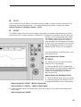
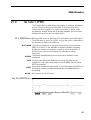
5.9 Examining with
VIEW
A curve examine mode available on the FCS-926 is also available on
the 900r. View is enabled from within the Utilities menu. Press the
UTILS key, select the strip under VIEW and turn the parameter control
to make the box display ‘ON’. The cursor will change as shown in
figure 5.2. The parameter status boxes now only show the frequency
of the cursor and the dB cut/boost value (or values) of the displayed
curve at the cursor position. Turning the FREQUENCY control now
moves the cursor back and forth along the curve allowing the user to
read off the exact boost value at any point.
Refer to Section 9.2 ‘Utilities’ - VIEW.
Fig 5.2
View mode ON
31
VARICURVE
S Y S T E M
TM
Examining with View
Scrolling the Display
5.10 Scrolling the
display
The display can be scrolled up or down to see the peaks or troughs of
any heavily boosted curves. The View cursor can be used in
conjunction with the scrolled display to read off the values of peaks
that would normally be off the screen.
Refer to Section 9.2 ‘Utilities’ - VSCROL.
32
STORE
6.0
STORE
Quick Reference
1
Press STORE.
2
Turn the Parameter control to select a program
number.
3
Enter a name, if required, using the numeric keys.
4
Press STORE a second time to complete the Store
function.
There are 50 program memories available in each Varicurve device, all
of which are available at the FPC-900 Remote. Each program memory
consists of the filter parameter settings along with the device input gain
settings, peak fix status and access mode (Stereo/Mono/Dual).
NOTE: Store will not store programs on an Omnidrive device. Omnidrive
programs must be stored in the Omnidrive itself.
In addition to the 50 device program memories, there are 12 special
program memories within the Remote designed for the storage of
Room Curves. These are named R1 to R12 and follow on from
program 50. Room Curves are equalisation curves produced from RTA
measurements and are a record of the equalisation characteristics of an
acoustic environment such as a studio, theatre or concert hall. Room
Curves are produced by the Room Curve function in the RTA menu
and are used by the Auto EQ function to reproduce the same response
in another location. It is also possible to create Room Curves manually
and Store them in locations R1-12.
Refer to Section 12.0 - ‘Make and Add Curve’ and Section 13.0 'Auto EQ'.
The first press of the STORE button changes the Program box in the
status bar to indicate the destination program number for the current
EQ. (See figure 6.1).
Fig 6.1
Storing a program
33
VARICURVE
S Y S T E M
TM
Naming Programs
INDEX in Store Mode
Turn the Parameter control to choose a program number to Store to.
Programs 1 to 50 are device programs. Programs R1 to R12 are
intended for Room Curves.
6.1 Naming
Programs
A new name can be entered using the Device keys. To use the
characters in boxes, (!, #, *, etc.) press and hold Shift and then select
the relevant Device key.
The second press of the STORE key will complete the process.
To leave the function at any time before Storing the data, press the
Speed Strip or select another key.
The user will not be allowed to Store into any program that is locked.
Lock is denoted by a key symbol next to the chosen program number
in the status bar.
To lock or unlock a program Refer to Section 9.2 ‘Utilities’ - PRGLCK
If AUTOLK is set to PROMPT, the user will be asked whether or not to
lock the program after the second press of the STORE key.
Refer to Section 9.3 'MORE Sub-menu' - AUTOLK.
6.2 INDEX in Store
mode
34
A full index of the programs already Stored in a device is available by
pressing INDEX after the first STORE key press. Adjusting the
destination program number will move the cursor along the index.
Locked programs are indicated with a key symbol.
RECALL
INDEX in Recall Mode
Recalling Between Devices
7.0
RECALL
Quick Reference
1
Press RECALL.
2
Turn the Parameter control to select a program
number.
3
Press RECALL a second time to load the EQ into the
current device.
RECALL is used to load any of the 50 stored programs within a
Varicurve device into the current program and filter hardware. If the
user wishes to browse through several stored equalisation programs
then please refer to the Section 8.0 ‘COMPARE’.
The first press of the RECALL button changes the Program box in the
status bar to indicate the source program number and its associated
name. The equalisation display will change to show the equalisation
curve stored in the chosen program but the device filters will not be
altered at this stage. Turn the Parameter control to choose a program
number. As each program is selected, its curve will be displayed.
NOTE: Only those programs which have been stored in the same access
mode as the current access mode will be available. The Parameter
control will skip over all others.
NOTE: Omnidrive programs cannot be recalled from the FPC-900R.
Once a program has been chosen press Recall a second time. The
filters in the current device will then be updated with the equalisation
data. The new program number is now displayed in large characters in
the Program box in the status bar. If the recalled equalisation is now
altered in any way, the program number will change to small
characters indicating that the current EQ no longer matches the stored
data. Recalling a Room Curve will send new filter parameters to the
current Device but not Program changes.
To leave the function at any time before Recalling any data, press the
Speed Strip or select another key.
7.1 INDEX in Recall
mode.
A full list of the programs already Stored in the device is available by
pressing INDEX after the first press of RECALL. Adjusting the source
program number with Index on will move the cursor within the index.
Locked programs are indicated with a key symbol.
7.2 Recalling
Between Devices
To recall a stored program from another device into the current device,
press RECALL followed by the Device key for the device from which
you wish to copy. You can now choose a program to Recall from the
selected device. To finish, press RECALL a second time.
35
VARICURVE
S Y S T E M
TM
COMPARE
RECALL in Compare Mode
8.0
COMPARE
Quick Reference
1
Press COMPARE.
2
Turn the Parameter control to listen to each of the
available programs.
3
Press RECALL to load an EQ into the current device
or press COMPARE again or touch the Speed Strip to
escape.
COMPARE is intended to allow the user to listen to the effect of each
stored equalisation, in turn, on the current audio programme. The
current equalisation can be compared with a stored one and the new
one Recalled if required.
The first press of the COMPARE button changes the Program box in the
status bar to indicate the compare program number and its associated
name. The equalisation display now shows the previous EQ contour in
the form of dots while the browse EQ is shown as a solid curve. The
filters in the current device are changed to allow the user to hear the
effect of the stored EQ.
Turn the Parameter control to browse through the stored programs 'online'.
Only those programs which have been stored in the same access
mode as the current access mode will be available. The Parameter
control will skip over all others.
A second press of the COMPARE key will turn off the Compare
function and return the original EQ. This allows the instant comparison
of the sound of a stored EQ with that of the current one by repeatedly
pressing COMPARE. This also means that if the current EQ has been
changed, it can easily be compared with the original stored version.
8.1 RECALL in
Compare mode
If the user wishes to recall the Compared program to the current
device, press RECALL.
The new program number is now displayed in large characters in the
Program box in the status bar. If the recalled equalisation is now
altered in any way, the program number will change to small
characters indicating that the current EQ no longer matches the stored
data.
36
INDEX in Compare Mode
8.2 INDEX in
Compare mode
WARNING!
A full list of the programs already Stored in the device is available by
pressing INDEX after the first press of COMPARE. Adjusting the source
program number with Index on will move the cursor within the index.
Locked programs are indicated with a key symbol.
Since entering the Compare mode allows an on-line browse through
previously stored and possibly very dissimilar programs, care must be
exercised to avoid system or loudspeaker damage.
37
VARICURVE
S Y S T E M
TM
Utilities Menu
9.0
Utilities Menu
Quick Reference
9.1 UTILS
1
Press UTILS
2
Select a menu item by pressing the speed strip
directly below the required item.
3
Turn the parameter control to adjust the item value.
You will by now have noticed the screen scrolling up to display a
menu whenever the RTA or UTILS key is pressed. This ensures that
Menu selections only take up screen space when there are options to
be set, or for setting up and using one of the many equalisation tools
available in the FPC-900r. Some of the more important adjustments in
the UTILS menu have already been referred to.
The UTILS menu contains all the basic operating controls of the FCS926 and FCS-920 Varicurve devices other than the standard filter
values. It also contains some of the more useful data handling tools
such as the Transfer menu. The following section covers each of these
menu items in more detail.
The items available on pressing UTILS are:
FADE
Adjusts the crossfade time of the Varicurve program changes.
GAIN
Adjusts the signal gain of the current Varicurve channel.
MONO
Switches the Varicurve device between Dual and Mono modes.
BYPASS
Switches the Varicurve device in and out of circuit.
MUTE
Mutes the output of the current Varicurve channel.
PRGLCK
PK FIX
VSCROL
CARD
Locks the peak values of filters to prevent filter interaction.
Scrolls the equalisation display up and down.
Enters the CARD Menu.
XFER
Transfers data to and from the Varicurve devices and the remote.
VIEW
Enables the user to read level values directly from the eq curve.
MORE
38
This locks a program against being edited.
AUTOLK
Accesses the UTILS sub-menu.
Selecting MORE on the main UTILS menu takes the user through to a
secondary menu. This contains the following:
This selects whether or not a program is locked when Stored.
MICSEN
Sets an input sensitivity level for a calibrated microphone.
PINK
LOKOUT
MORE
9.2 Action of
Utilities
Turns the interface pink noise output on and off.
Locks out various controls on the Remote to prevent tampering.
Returns to the main UTILS menu.
Following each menu item name is the area of the system that it applies to. These area references are duplicated in the bar across the top
of the menu items. Items marked Channel will affect the Varicurve
device currently selected. Items marked Remote will only affect the
remote or its interface.
FADE Pressing a Device Key will change the currently selected channel
whilst keeping the same Menu and Item selected on the screen.
(Channel)
[Adjust value -6.0S to +6.0S]
FADE adjusts the crossfade time of the Varicurve program changes.
Positive fade time is the time taken for one EQ contour to be faded
down and the replacement contour faded up. Negative fade time will
merge from one EQ contour into the new one. Cross fading only
applies to program recall.
GAIN (Channel)
[Adjust value -12dB to +12dB]
This item adjusts the overall gain of the current Varicurve channel.
Adjust the input gain from -12dB to +12dB in 0.5dB steps. When an
EQ is stored into a program memory this gain value is also recorded. In
stereo mode, both channels are adjusted simultaneously whilst keeping any gain offset between them constant.
When extreme EQ contours have been set, it may become necessary to
restore the correct operating level by adjusting input gain.
MONO (Channel)
[ON, OFF]
This selects the configuration of the filters within a Varicurve device.
With MONO set to ON, all 12 filters are assigned to Channel 1. With
MONO OFF the filters are split between two 6 filter sets.
When MONO is OFF, use the Device keys to select whether the device is in Dual or Stereo modes.
Refer to Section 4 ‘Selecting a Device’ to read more about switching
between Stereo and Dual modes.
Programs stored in any one of these modes will not be available for
recall if the device is switched to a different mode.
39
VARICURVE
S Y S T E M
TM
Utilities Menu
BYPASS (Channel)
[EQ IN, EQ OUT]
Bypass switches the Varicurve device in and out of circuit.
With EQ IN the device is in circuit. With EQ OUT the EQ circuitry is
bypassed by a relay ensuring signal flow even with the power off. This
control affects both channels within a 920 or 926.
MUTE (Channel)
[CH ON, MUTED]
Mutes the output of the current Varicurve channel.
Select between CH ON representing ‘Channel On’ and MUTED
representing ‘Channel Off’.
(Channel)
[OFF, ON]
PRGLCK This selects the control and adjustment lock out on individual
programs.
Selecting ON ensures that the currently selected Program memory is
protected and cannot be overwritten. Selecting STORE while Program
Lock is on will confirm the protected status by displaying a PROGRAM
LOCK warning menu. If PRGLCK is set to ON or AUTOLK in the UTIL
Sub-menu, the remote will prompt whenever a program is Stored as to
whether the user requires the program to be locked or not.
PK FIX (Channel)
[OFF, ON]
Select between ON and OFF. Selecting ON instructs the internal
control circuits to record each filter’s boost or cut value and hold the
peak constant while other filters are adjusted. The consequence of this
is to minimise the interaction effect on a filter when an adjacent one is
adjusted. Note that if one channel only is peak fixed and the two
channels are subsequently stereo linked, then peak fixing will remain
on one channel only. If peak fix is changed in stereo mode however,
both channels peak fix status will change together.
Operation of the peak fix option may cause the display redrawing to
slow.
VSCROL (Remote)
[Adjust value -16dB to +16dB]
This allows the horizontal 0dB axis of the screen to be scrolled up and
down.Adjusting this value will shift the display up or down allowing
large filter peaks or notches to be viewed more easily.
CARD
(Remote)
Selecting CARD will access the Smart Card Menu.
Refer to Section 17.0 'Smart Card'
40
Utilities Sub-menu
XFER (Remote)
Selecting XFER will access the Menu containing options linked with
transfering program data through the Midi port or over the FSK link.
Please refer to Section 16 - ‘Data Transfer’.
VIEW (Remote)
[OFF, ON]
This enables the filter VIEW mode.VIEW is a contour viewer allowing
the parameter control to move the cursor from one end of the display
to the other. The Frequency value in the status bar will give the
position of the cursor while the boost/cut reading gives the level of the
contour at the cursor position. In VIEW mode the filters cannot be
adjusted and so this gives a basic protection to the contour data on the
display.
MORE Selecting MORE will access the second utilities sub-menu.
9.3 MORE sub-menu
MORE is a sub-menu containing less used Utilities and is entered by
selecting MORE after pressing the UTILS button.
AUTOLK (Channel)
[OFF, AUTOLK, ON]
With AUTOLK selected the remote will prompt the user whether to
Lock or Unlock a program whenever it is Stored. This will allow the
user to Store programs Locked rather than having to go back and Lock
them later. With ON or OFF selected all programs will be stored either
Locked or Unlocked respectively. When the user attempts to Store into
a locked program a warning will be displayed on the screen.
MICSEN (Remote)
[2mV to 20mV in 0.5dB steps]
This adjusts the sensitivity of the analyser microphone input. It should
be adjusted to the value supplied on the analyser microphone data
sheet.
PINK (Remote)
(OFF, ON)
This item turns the FPC-900i interface pink noise output on or off.
LOKOUT (Remote)
[UNLOCK, SHOWTM, LOCKED]
This selects various levels of control and adjustment lock out on the
remote unit.
With this item set to LOCKED the remote will not allow any changes to
be made to a device from the remote. When SHOWTM is selected
programs can be recalled and events actioned but neither can be
stored to. With it set to UNLOCK the remote will operate normally.
MORE Returns to the UTILS menu.
41
VARICURVE
S Y S T E M
TM
Grouping
GROUP
10.0 Grouping - GROUP and ALL
Quick Reference
Press ALL or GROUP.
Use the Device Keys to enter channels into, or remove
channels from the Group.
Adjust the available filters in the normal way.
Press UTILS to access the Group mute and gain.
The Group functions - GROUP and ALL - on the FPC-900r allow the
user to adjust filters on a collection of Varicurve channels
simultaneously. In addition to the standard three filter parameters there
is also access to a Group Utils menu allowing Muting and Gain
control across a selected Group. Because the filter parameters of
Varicurve channels can be very different when they are grouped, the
FPC-900r has to decide which filters to link together from the various
devices. The boxed section on page 39 details the precise rules
followed in Grouping filters.
10.1 GROUP
Pressing GROUP will prepare a Group containing the last used
selection of Varicurve channels. Either six or 12 filters are available in
Group depending on the access of the members of the group. If all the
group members are mono then 12 filters will be available. The remote
will attempt to assign as many filters as possible from each member to
the Group filters. The decisions used in assigning the filters are
covered on page 39.
Once the GROUP led is on, the Device Keys are used to flip channels
in and out of the group. The channel leds will indicate the members of
the group. The assigned group filters are marked with triangles along
the bottom of the screen in exactly the same way as for an individual
channel. Spare filters are numbered in the top right corner of the
Fig 10.1
Group mode
42
GROUP
Group UTILS
screen. See fig 10.1. The Group curve is always displayed as flat on
entry, representing a starting point for all the members of the group. An
adjustment made to the group curve will be made to all channels that
have appropriate filters available.
NOTE that the relative differences between the parameter values of the
group members are always preserved. This means that if a one member
of a group reaches a limit whilst a parameter is being adjusted, no
further adjustment can be made to the group parameter in that
direction.
If a channel led is flashing it indicates that that channel does not have
a filter at, or near the frequency of the selected group filter. Adjusting
the group filter will have no effect on that channel. To make an
adjustment at that frequency on the whole group would require a
spare group filter. The speed strip can be used to select another of the
group filters, or to select a frequency to position one of the spare
filters. Spare group filters are only available if all members of the group
have spare filters.
Pressing GROUP a second time will turn off the Group mode and
return the user to an individual channel. The combination of group
members is stored for the next time that group is used.
10.2 Group UTILS
Pressing UTILS whilst in GROUP mode will bring up a Group version
of the utilities menu. Only two items are available here - Gain and
Mute. Select one and adjust using the parameter control. See fig10.2.
NOTE that because the Mute information is transmitted as a Gain
value, a change in Gain will not be displayed by a FCS-926 if the
channel is muted. Always adjust the channel Gains with the channel
on.
Press UTILS again to return to the group filter display.
Fig 10.2
Group UTILS
43
VARICURVE
S Y S T E M
TM
ALL
10.3 Group ALL
ALL is a special case of Grouping. Pressing the ALL key will open a
group containing all the available Varicurve channels connected to the
system. The channels are scanned for compatible filters and a flat
group curve is displayed. All of the group facilities are available to the
‘All’ members. The Channel Keys will add or remove members from
the All selection but the resultant combination of members is not
preserved when ALL is turned off.
GROUP ASSIGNMENT
When several channels are entered into a group, the FPC-900r
follows several simple rules to select the filters available on the
Group display.
$ A record is kept of all the filter frequencies used by the group
members.
$ Each filter is rated according to how large its cut or boost
parameter is. The greater the cut or boost, the higher the score
for that filter. Narrow notches are also given a higher score.
$ The six or 12 highest scoring frequencies are used as the group
filters for the display.
$ Each Varicurve channel in the group is now scanned and an
attempt made to match each channel filter to a group filter.
$ If there are no spare filters then that group filter will have no
effect on the channel when it is adjusted - this is indicated by
the channel led flashing when this group filter is selected.
44
RTA (Real Time Analyser)
RTA Menu
11.0
RTA (Real Time Analyser)
The FPC-900r has access to both its own internal Real Time Analyser,
working on the remote RTA microphone input, and also the RTA of
each Varicurve device attached to the midi system. The RTA output is
displayed as 30 RTA frequency bars which can be overlaid over the
EQ contour. The RTA also has the capability of automatically adjusting
a Varicurve device to correct a measured response to be as close as
possible to flat or to a user defined contour.
Refer to Section 13.0 ‘Auto EQ’ for details of the Auto EQ system.
The Real Time Analyser has six dedicated memories, each of which
can store a complete 30 band RTA output graph. These can be used
individually or summed together as a target for the Auto EQ facility.
The memories are labelled A to F to differentiate them from the EQ
program curves.
The Real Time Analyser output can also be used to display an SPL
(Sound Pressure Level) meter when used with a calibrated microphone.
11.1 RTA Menu
The following menu items are available by pressing the RTA key. To
select an item to change, press the Speed Strip below the item. A list of
options on the selected item will appear above the menu. Use the
Parameter control to change between the options available for the
selected menu item. Press the RTA switch again to return to the normal
filter editing mode. Pressing a Device key will change the currently
selected channel whilst keeping the same Menu and Item on the
screen.
NOTE that the items marked (Channel) will only apply to the currently
selected device channel.
NOTE also that some of the RTA functions are not available in all
modes of the RTA system, e.g., with the SPL meter on, it is not possible
to run the Auto EQ function. Any items not usable in the current mode
are removed from the menu when that RTA mode is selected.
Fig. 11.1 RTA Menu
45
VARICURVE
S Y S T E M
TM
RTA Menu
DISP (Display)
[OFF, DEVRTA, INTRTA, INTSPL]
This item selects the display mode for the RTA and SPL bargraph.
DEVRTA will select an RTA display generated from the selected device
channel. With DEVRTA selected the exact source within the device
(Input, Output or Mic) is chosen in the SOURCE item detailed below.
INTRTA and INTSPL both use the remote’s Mic socket as the source.
INTSPL will create a single bargraph displaying the signal level
received by the microphone. Weighting can be selected from the
EIGHT item detailed below. DEVRTA will not operate over the FSK
link since it requires two-way communication.
DECAY (Display)
[Adjust value 100mS to 10S or INF]
This adjusts the decay time of the RTA display bars. For Peak mode the
decay rate is adjustable from 100mS to 5 Secs with an extra step for
INFinite hold. For RMS mode the decay rate is adjustable from 100mS
to 10 Secs.
BALIST (Display)
[RMS, PEAK]
This item sets the ballistics of the RTA bars or SPL display bargraph.
SOURCE (Display)
[INPUT, OUTPUT, MIC]
This item selects the RTA signal source and is only displayed when
DISP is set to DEVRTA.
With INPUT selected the source will be the line input signal to the
selected device. Similarly OUTPUT will display the RTA of the device
line output. With MIC selected the remote will display the microphone
signal into the current device.
RTGAIN (Device/Channel) [Adjust value 0dB to 40dB (or 70dB internal)]
This adjusts the overall level of the RTA or SPL display. Use the
parameter control to adjust the RTA gain from 0dB to 40dB(or 70dB) in
1dB steps. If RTA gain is set too high the arrow shaped clip indicator
will show in the top left hand of the display area.
With the SPL meter selected in DISP this box will adjust the range of
the SPL display, from 50dB to 140dB in 10dB steps.
HOLD (Display)
[ON, OFF]
This item turns the RTA Hold On and Off. The RTA display will be
held stationary when this item is set ON. This is useful for grabbing
RTA curves ready for storing in an RTA memory.
CURVE (Local)
[ON, OFF]
This turns the current EQ curve on and off. The CURVE box is only
displayed when the SPL meter is off.
46
RTA Memories
Storing an RTA
Recalling an RTA
SPL WT (Local)
[OFF, A-WT, C-WT]
This sets the weighting for the SPL Bargraph display and is only
displayed when DISP is set to INTSPL.
Refer to Appendix 18.4 - 'Frequency Weighting Characteristics'
PKHOLD (Remote) [Adjust value 0.1S to 5S, OFF and INFINITY]
Adjusts the hold time of the RTA peak dots.
PINK (Remote)
[OFF, ON]
This item turns the FPC-900i interface pink noise output on or off.
AUTOEQ (Channel)
[Select to start]
Selecting this item will start the auto-equalisation ulitity.
Refer to Section 13.0 - ‘Auto EQ’
ADD (Remote)
[Turn parameter to start]
This item allows two EQ contours to be added together.
RMCURV (Remote)
[Select to start]
Converts the currently displayed RTA into an EQ Contour.
Refer to Section 12.0 - ‘Room Curve and Add Curve’ for more
information.
11.2 RTA memories
Real Time Analyser graphs can be stored in one of six specialised
memories. Stored RTA memories can be used by the Auto EQ function
to generate EQ curves to null a measured room RTA.
11.3 Storing an RTA
With the RTA menu on the screen select STORE. The parameter
control will now adjust the memory letter A to F as indicated in the
status area. Store is completed by pressing STORE again. It is possible
to exit from Store RTA without changing anything by pressing the
Speed Strip. It is not possible to name or lock RTA memories.
11.4 Recalling An
RTA
With the RTA menu on the screen select RECALL. The parameter
control will now adjust the memory letter A to F as indicated in the
status area. Recall is completed by pressing RECALL again. The RTA
will be recalled in Hold mode ready for running an Auto-EQ. It is
possible to exit from Recall without changing anything by pressing the
Speed Strip.
47
VARICURVE
S Y S T E M
TM
Room Curves
ROOMCV
12.0
Room Curve and Add Curve
Quick Reference
Room Curve will convert an RTA display of bars and
convert it to an eq curve.
Add Curve will add a stored eq curve to the current eq
curve.
These two utilities are to be found in the RTA Menu and can be
accessed by pressing the RTA key and then selecting one of them using
the speed strip.
12.1 Room Curves
Each environment in which the remote is used will have a
characteristic response curve which can be measured and stored using
the Real Time Analyser built into the FPC-900r. This curve will be a
record of the frequency response of the room either flat or after the
user has added equalisation to the sound source. The FPC-900r has
twelve program memories set aside for storing these room curve
records.
It may be that a good sound has been created by careful use of the
Varicurve equalisers and the resulting, adjusted room response is
recorded to either duplicate at a later time with a different band at the
same site or to use as a optimum equalisation response at a different
venue. Room curves created from an RTA response can, of course, be
used as the target response for the Auto EQ system detailed in the next
Section.
12.2 ROOMCV
Fig. 12.1 Add Curve
48
This utility is only available when there is an RTA bar display on the
screen. Selecting ROOMCV on the speed strip and turning the
parameter control will run the utility. The room curve algorithm
calculates filter parameters which best approximate the curve
produced by the
ADD Curve
RTA pattern. If the curve is too complex for the available filters to
approximate, the shape is simplified by smoothing. If the current
device is in Stereo mode, the curve will be created using 6 filters and
copied into both channels of the device. In Dual only the current
channel is used. If the device is in Mono mode, the curve will be more
precise, using all 12 filters if necessary.
Once finished, the Remote will change to Store mode, prompting the user
to store the resultant curve in one of the twelve Room Curve memories (or
a program memory in the current device). Rooms 1 to 6 are locked presets
which may be unlocked and overwritten. To unlock one of the 6 factory
presets, recall the curve into the current curve in Dual access mode and
select PRGLCK in the UTILS menu. Room Curves can only be recalled
when the device is in the same access mode as when the curves were
stored. The factory preset Room Curves can therefore only be recalled
into a Dual access mode device even though they can be used as a target
curve for any access mode in Auto EQ.
Refer to Section 6.0 ‘STORE’.
Note: There is only one set of 12 Room Curves available within the
remote, there are no Room Curve program locations in the individual
devices.
12.3 ADD Curve
Add Curve uses many of the techniques employed by Room Curve.
With Add Curve the user can take the current equalisation curve and
add another stored program curve to it. Selecting ADD in the RTA
menu will enter the Add Curve Menu.
DONE
Will leave this menu and return to the RTA Menu.
PROG
Select PROG and use the parameter control to select a stored program
to add to the current equalisation curve.
START
Select START to begin the addition.
Note: The program to be added must be in the same mode (Stereo,
Dual, Mono) as the current device. Any programs that are in the wrong
access mode will be stepped over.
When this process is started, the two curves will be added at each of
the 210 frequency points available to the system. This will create a
composite curve which may be too complex for the number of filters
available, so the utility will simplify the contour by smoothing so that
the available filters are able to duplicate the new curve. As with Make
Curve, up to 12 filters will be used in Mono mode and up to six in
Dual or Stereo.
The new curve can now be stored in a program memory in the current
device or into one of the 12 room curves stored in the remote itself.
Refer to Section 6.0 ‘STORE’.
49
VARICURVE
S Y S T E M
TM
AUTO EQ
A Simple Auto EQ
13.0
AUTO EQ
Quick Reference
1
Press RTA, select AUTOEQ.
2
Select the current RTA or a mixture of the stored RTAs
as the present response.
3
Select a target response curve in Contour.
4
Select START
The Auto EQ function allows the FPC-900r remote to adjust a room
equalisation curve in response to a measured RTA in the same way as
the FCS-926 Auto EQ. Pink noise is injected into the audio system and
the output from the system measured with the FPC-900r internal Real
Time Analyser. The remote takes the RTA graph and uses it to calculate
an equalisation curve that will attempt to correct any frequency
response errors in the environment (or circuitry) that produced the
RTA. The box below details how the Auto EQ works.
13.1 A simple AUTO
EQ
The FPC-900r is very flexible in the RTA information it can use. The
easiest source of a room response measurement is the current RTA
reading.
! Press the RTA key to enter the RTA menu.
" Start the RTA by adjusting the DISP menu item to INTRTA.
# Plug a microphone into the remote’s RTA input.
% Press the UTILS key and select MORE. Adjust the PINK item to turn
the pink noise source in the rack interface on. Connect the pink
noise output from the interface to the system to be measured.
Fig. 13.1 AUTOEQ Using
the Current RTA
50
Mixed RTA Sources
& Return to the RTA menu and adjust the RTGAIN item to show the
frequency response of the pink noise across the analyser bars.
Avoid the clipping indicator showing in the top left of the screen.
BALISTics should be set to RMS and DECAY to at least 1 Second.
Longer times will require more settling time. Wait for the bars to
settle and select HOLD ON.
' Select AUTOEQ. The AUTOEQ menu will be drawn. Select
CURENT to use the current RTA as the source response to work on.
Select Contour and choose a target equalisation curve to adjust to.
(Program R1 will equalise to FLAT).
( Select START to begin the Auto Equalisation function.
) The resulting curve can be stored or the process repeated with a
different RTA graph used as the source data.
13.2 Mixed RTA
Sources.
In addition to using the current RTA graph as the measured room
response, it is possible to use one, or a mixture of two or more, of the
stored RTAs in the remote. If different RTA measurements are taken
from different points in the venue, the user can use an average of each
of the RTAs to create a composite room RTA. Different parts of the
room can be weighted differently - Front of House could count as 60%
of the room RTA whilst the side areas take 20% each.
The six menu items in the AUTOEQ menu labelled A: to F: represent
the six RTA memories. The small graphs in each box are a
representation of the stored RTA measurement. When a box is
selected, the parameter control can adjust the amount of the RTA
added from that memory into the displayed mix from 0 to 100%. The
resultant sum of the various RTA memories will be the room RTA that
is plugged into the AUTO EQ calculation. The sum of the memories is
constantly updated and displayed on the screen.
Note that, although the values are displayed as percent, the total RTA
will never add up to more than 100%. Dialling up 100% for two
different memories will result in a average made up of half of each.
Exactly the same effect is given by selecting 20% from each. Don’t
worry about having to make the total add up to 100% - it always ends
up being one complete RTA.
Fig 13.2 AUTOEQ using a
Mix of RTAs
51
VARICURVE
S Y S T E M
TM
Target Room Curves
13.3 Target Room
Curves
The Contour box allows the user to select a response curve that
describes the desired frequency response for the room being equalised.
Generally the user will stick to curve R1 which is FLAT or possibly
curve R2 which has 3dB/octave roll offs at top and bottom. The
possibility also exists to use other stored equaliser curves. It might be
that the requirement is for a sound that always has 6dB of boost at
10kHz. If so, use the standard filter controls to create the curve and
store it in one of the device program memories or overwrite one of the
remote Room curves (R1 to R12 - Refer to Section 6.0 ‘STORE’). The
stored curve can now be selected in the Contour item to be the target
response for the next AUTOEQ calculation. The chosen response
curve is always displayed on the screen whilst in the AUTOEQ menu.
One further possibility is to use the RTA measured at one venue to be
the target equalisation at another.
! Measure the RTA at the first venue and use the ROOMCV facility in
the RTA menu to turn the RTA graph into an EQ curve.
(Refer to Section 12.0 ‘Room Curve and Add Curve’).
" Store the resultant curve into one of the remote Room curve
memories e.g. R7. (Give it a name so it doesn’t get overwritten.)
# At the second venue set up the RTA to measure the room response
and perform an AUTOEQ using the response curve stored in R7 as
the target response. The second venue will be equalised to give a
room response similar to the first venue.
AUTO EQ - How it works.
After inverting the combined RTA response and adding to it the
target curve, a sophisticated algorithm analyses the resultant curve
and calculates the filter parameters required to match the resultant
curve. If the curve shape is too complex for the number of filters
available, it is simplified by smoothing. To prevent filters being
wasted by trying to compensate for impossible deficiencies of the
system or environment at the extremes of the frequency response,
AUTO EQ will not analyse nor allocate filters to frequencies
beyond the end points where the target curve falls more than a
few dB below the 0dB centre line.
AUTO EQ on a stereo device will produce the same curve on
both channels whereas only one channel of a dual device will be
affected.
52
EVENT
Event Edit Screen
14.0
EVENT
Quick Reference
Press EVENT to enter the Event menu.
Trigger an event by pressing the Speed Strip under the
appropriate event box.
Step through consecutive events by selecting STEP ON
and then step using the EVENT key.
The Event system on the FPC-900r gives the user the ability to send a
Midi program change out on each Midi channel, whether or not it is a
Varicurve or Omnidrive device. These Events are fired off by selection
from the speed strip or by enabling the EVENT key to step sequentially
through a list of programmed Events.
There are two screens concerned with Events. The first press of the
EVENT key takes the user into the main Event Select menu. Here the
Events are selected and triggered. First, however we must create some
Events to use.
14.1 Event Edit
Screen
After the first press of the EVENT key to enter the Event Select menu,
select EDIT using the speed strip. The display now enters the Event
Edit display. See fig 14.1.
EVENT NO Selects the number of the Event to edit. 50 Events are available.
NAME Allows the user to give the current event a name.
PROGRAM Select this to assign a program change to a device.
DEST This selects an Event to copy the current event to.
COPY This will begin the Event copy.
DONE Will return to the main Event Select menu.
Fig. 14.1 Event Edit
53
VARICURVE
S Y S T E M
TM
Event Edit Screen
The screen lists each available device in a similar format to the device
Index screen. If a device is identified by the FPC-900r, the centre
column will show 920, 926 or 388. Either side of the device data are
one or two device names, depending on which mode - Mono, Stereo
or Dual - that the device is in. At the ends of each device entry are the
Program changes for this device in the current Event. If no program
change is selected for this device the program number is noted as 'off'
with a bar ‘—’. If the access mode for the chosen program does not
match the access mode of the current device, an exclamation mark (!)
will be displayed after the program number.
EVENT NO [Adjust value]
Select this item with the speed strip and turn the parameter control to
choose an Event to edit. When Event edit is entered this will default to
the last triggered Event.
50 events are available in the FPC-900r.
NAME [Enter name with Device keys]
Select this item to change the name of the current Event. When
selected this item will display the last assigned name until letters are
entered from the Device keypad. The Device keys now enter letters
into the event name. Select another menu item with the speed strip to
finish entering the name, there is no Enter key to press.
PROGRAM [Adjust value]
This item changes the program numbers assigned to the devices. With
this item selected the Device keys move between the available devices
in the display. Selecting a device with the Device keys will highlight
the program number text for that device. The assigned program
number for that device is duplicated in the PROGRAM box along with
the program name. If the selected channel is not a Varicurve device
the program number can still be adjusted from 1 up to 128 but the
device type area at the centre of the line will show ‘???’ to denote an
unknown device.
Once a program number has been assigned to a channel, select
another device with the Device keys and adjust that with the
parameter control, continuing until the event is complete.
DEST [Adjust value]
To copy the program changes of one Event into another first use the
EVENT NO box to change to the source event, the one you wish to
copy FROM. Now select DEST and adjust the Event to copy to, again
using the parameter control. Once the destination has been set, select
COPY.
54
Event Select Menu
Triggering Events
COPY [Select to begin copy]
All the program changes linked to each device will be copied into the
destination Event along with the source program name.
DONE When all changes have been made to your Events, return to the Event
Select menu by choosing DONE. All changes will have automatically
been saved.
14.2 Event Select
Menu
The figure below (fig 14.2) shows the main Event Select screen.
EDIT Select this item to enter the Event Edit menu.
STEP If this box is ON, the Event key can be used to step through Events
DONE Selecting DONE will return to filter editing.
The first seven boxes detail seven of the 50 available Events. After an
Event has been triggered, these seven boxes will be centred on the last
triggered Event. Below the Event numbers are the user defined Event
names. The last triggered Event is always marked with the word ‘LAST’
alongside the Event number. To scroll through all 50 Events turn the
parameter control. The events available along the speed strip will
scroll as the control is turned.
14.3 Triggering
Events
STEP
Any of the seven Events visible above the menu can be immediately
fired by selecting it with the speed strip. Alternatively the Event key
itself can be used to trigger Events by enabling STEP.
[OFF, ON]
With STEP selected to ON, the EVENT key can be used to step
sequentially through the programmed Events. This is useful if a show
has been built up which only requires each Event to be actioned in
numerical order. Once enabled the Event led will flash. Each press of
the EVENT key will now step to the next Event. This facility is not
available outside of the Event Select menu.
Fig. 14.2 Event Select
55
VARICURVE
S Y S T E M
TM
INDEX with Events
EDIT [Select to enter]
Select EDIT to enter the Event Edit screen.
DONE Selecting DONE will return to the main equalisation curve.
14.4 INDEX with
Events.
Fig. 14.3 Event Index
56
INDEX can be pressed while in the Event Select screen to give a
complete list of all the Events available from 1 to 50 along with the
Event name. See fig 14.3. Turning the parameter control will move the
highlight through the Index at the same time as the Events are scrolled
along the speed strip. The highlight will always correspond to the
Event in the centre of the seven available on the speed strip. The Event
must still be triggered by selecting it from the speed strip. Press INDEX
again to return the display to the normal Event Select screen.
XFER (Transfer)
15.0
Transfer (XFER)
The Transfer menu is used to pass information to and from the remote
and the Varicurve devices on the system. It should be used if the
remote has been plugged in to a Varicurve system or device where
programs are already stored and Eq already prepared. Data cannot be
transferred to and from an Omnidrive device.
15.1 XFER Menu
Enter the XFER menu by pressing UTILS and selecting the XFER option.
The XFER menu is shown in fig 15.1. Only a few option combinations
are allowed, all others are locked out.
DATA AREA The Data Area item sets up the type of data that is to be transferred.
PROG 1 to PROG 50 are available to transfer individual programs.
DUMP will transfer the complete contents of a Varicurve device. A
DUMP from a Device to the Remote will take approximately
20seconds.
SOURCE The Source item defines the source from which the data is to be
transferred.
DEST The Dest item defines the destination to which the data will be
transferred. Only a few combinations of DATA AREA, SOURCE and
DEST are available.
START Select Start to begin the data transfer. In a DUMP mode the START box
will display a percent of data transferred while the data transfer is
proceeding.
DONE
Will return to the UTILS menu.
Fig 15.1 XFER Menu
57
VARICURVE
S Y S T E M
TM
XFER (Transfer)
PROGs 1 to 50 can be transferred between REMOTE and DEVICE.
A complete Varicurve DUMP can be transferred from DEVICE to the
REMOTE or from ALLDEVS to the REMOTE. The user is protected to
some degree by an "ARE YOU SURE" message, to which the user must
respond by selecting 'YES' or 'NO' from the Speed Strip. DUMP will
overwrite all information linked with a DEVICE or ALL DEVices within
the FPC-900 so be careful before this option is used. DUMP should be
used when the Remote is connected to Varicurves that may have been
changed since they were last connected to the FPC-900 remote.
DUMP each DEVICE one at a time (or use ALLDEVs if all may have
been edited) to ensure that the program contents and current set-up of
the connected Varicurves is duplicated in the set-up of the remote.
NOTE that recalling a program in a Varicurve device only sends a
program change to the device and does not transfer the program
parameter data from the device to the remote, so it is essential that the
two match.
58
Smart Card
CARD Menu
16.0 Smart Card
The Smart Card socket on the front of the remote is designed to use
PCMCIA2 memory cards of between 128kbyte and 2Mbyte storage
capacity. Files are stored on the card in a ‘Pseudo-floppy’ format
using standard DOS structures. See the box at the end of this section
for compatibility information. As existing Flash memory cards have
erase and re-write limitations, only SRAM memory cards are fully
supported in the current remote Smart card software. The exception
is that a full remote set-up (an ALLDATA file) is stored to a Flash card
when it is formatted . The Flash card remote set-up can then be read
at any time, but only written to by performing a complete format
again. This is useful for archive purposes as Flash cards have no
batteries to run down. The FPC-900 has been tested using Fujitsu
256k FLASH cards.
NOTE:
Flash cards should be the older Series 1 Flash cards, newer Series 2
Flash cards may not work.
Omnidrive data cannot be stored or recalled on the FPC-900R
16.1 CARD Menu
Enter the CARD menu by pressing UTILS and selecting the CARD
option.
Across the top of the CARD screen are detailed the number of blocks
available on the card and the number of files of the selected data type
that can be fitted onto the card. The directory name at the top left of
the screen will always show BSSDATA. At the top right are the number
of files found of the current data type.
DATA AREA [CURVE, RTA, DEVICE, ALLDATA, EVENTS]
This item selects the area of data that is to be acted upon, whether it is
to be Loaded, Saved or Deleted. As this item is altered, the screen will
redraw to give a directory of the files of this type available on the card.
The maximum number of files of each type is limited by the amount of
card space available up to a limit of 90. If the data type is CURVE and
there are no curves stored, for example, the limit is 90 as each file is
very small. If the data type is ALLDATA, the maximum may be limited
by card size to 1 or 2, as each file is rather large.
Fig. 16.1 Card Menu
59
VARICURVE
S Y S T E M
TM
CARD Menu
CURVE
RTA
DEVICE
ALLDATA
EVENTS
60
Each file will be saved from the current data area of the appropriate
type. Saving a curve will save the current equalisation data for the
current device, saving a device will save the current device data and
so on.
Each area saves the following data:
In SAVE this saves the currently displayed program name followed by
the currently displayed equalisation filter parameters. To save a
program that is not in the edit area it must be recalled first. LOADing a
program will recall the data to the current edit area on the current
device. It should then be stored to a suitable program number. It is
possible to SAVE room curves by recalling them to the display in the
same way as programs. Only those curves saved with their access
mode the same as the current device can be loaded. The different
access modes, (MONO, STEREO and DUAL) are denoted by different
filename extensions when they are saved. Only curve files of the
current access type are listed in the file list.
Curve names have no link with the file names, any name can be used
for saving files.
This saves and loads the current RTA bargraph data. To save one of the
stored RTA graphs it should be recalled to the display first. The user
should select DEVRTA or INTRTA in the RTA menu before recalling
an RTA.
Selecting DEVICE will save and load the currently selected device
data. All program data and program names are included. Room curves
must be saved individually using CURVE, or as part of ALLDATA.
ALLDATA should be used for backing up a complete remote set-up. It
saves all 16 device datasets (whether in use or not), all RTAs, events
and many of the remote set-up variables. If FORMAT is selected with a
FLASH card in the slot, the card will be formatted with an ALLDATA
file using the current remote data. This allows FLASH cards to be used
for long term back-up. A FLASH card can be read in the same way as
an SRAM card with no restrictions.
Saving and LOADing EVENTS will save and load all event data
including names.
LOAD
[Enter Filename]
Select LOAD to recall data from a FLASH or SRAM card. Now turn the
parameter control to select a file from the file list or type in a name
using the numeric keys. Press START to complete the LOAD. After
loading a DEVICE or ALLDATA, the screen will go automatically to
XFER to remind the user to update the Varicurve devices.
SAVE
[Enter Filename]
Select SAVE to save data to a formatted SRAM card. Now turn the
parameter control to select a file from the file list to overwrite or type
in a new name using the numeric keys. Press START to complete the
SAVE. Saving a DEVICE or ALLDATA may take a few seconds. If the
file already exists, the user will be prompted "ARE YOU SURE?".
CARD Menu
DELETE [Enter Filename]
Select DELETE to choose a file to delete from an SRAM card. Now turn
the parameter control to select a file from the file list or type in a name
using the numeric keys. Press START to complete the DELETE. The user
will be prompted "ARE YOU SURE?".
FORMAT Select FORMAT to prepare a card for saving data. NOTE: that in the
same way that formatting a floppy disc deletes ALL data on the disc,
formatting a FLASH or SRAM card will delete all existing data on the
card. It is not possible to save data to an unformatted card. Formatting
a card clears all data and prepares the card for files to be written. See
the box following this section for more information on formatting.
Select START to begin the format. You will be asked to confirm that
you wish to format the card. Fig 16.2.
Formatting a FLASH card will also write an ALLDATA file to the card.
If a FLASH card is detected when a FORMAT is STARTed, the card is
formatted as usual and then a single ALLDATA file is written to the
card using the current remote data. No further SAVE operations can be
performed on a FLASH card although the saved ALLDATA file can be
LOADed at any time. As FLASH cards have a virtually limitless data
retention life compared to an SRAM card (which has a data retention
life of 1 to 5 years depending on card size) this is a good method of
handling long term backups. See the box at the end of this section for
information on the possibility of copying files to a PC.
START START will begin a SAVE, LOAD, DELETE or FORMAT operation.
DONE DONE will leave the CARD menu and return to UTILS.
NOTE The user will be warned if the internal SRAM card battery voltage
becomes low. The battery should be replaced as soon as possible to
prtect the stored data. The card has a small secondary battery to
protect the contents while the main battery is changed.
Fig 16.2 Are You Sure?
61
VARICURVE
S Y S T E M
TM
Card Types
16.2 Card Types
The Smart Card interface requires 68pin PCMCIA2 compatible
memory cards. Attribute memory is not required and is not used.
SRAM CARDS 128k, 256k, 512k, 1M, 2M. Battery life varies with manufacturer. As
an example Fujisoku 256k cards have an approximate life of 5.9 years,
2M cards have an approximate life of 1.1 years.
FLASH CARDS 256k, 512k, 1M, 2M. All FLASH cards are formatted as 256k with a
single ALLDATA file recorded on them. The FPC-900 has been tested
using Series 1 flash cards: e.g. Centennial FL256-20-1XXXX-XX.
Smart Card Format
The Smart Card filing system on the 900r remote uses a ‘pseudofloppy’ format. Formatting a Card on the 900r Remote writes a
standard PC DOS format to the card beginning at byte 0 as if it
were the first byte on a disc. The format writes a DOS boot sector
with basic format data but does not write boot software. This is
followed by a single File Allocation Table (FAT) starting at byte
200H. The root directory is written with one entry, a sub-directory
called BSSDATA. All data files used by the remote are stored in
the BSSDATA sub-directory as there are limits to the number of
files that can be stored in the root directory.
The different file types used by the remote have different file
extensions as follows. The file sizes should be taken as
approximate and may change with new versions of software.
CURVE (Mono)
CURVE (Stereo)
CURVE (Dual)
RTA
DEVICE
ALLDATA
EVENTS
*.CVM
*.CVS
*.CVD
*.RTA
*.DEV
*.ALL
*.EVT
97bytes
97bytes
97bytes
61bytes
4998bytes
83118bytes
2001bytes
The ‘pseudo-floppy’ filing system as used on the remote conforms
to the PCMCIA PC CARD standard although it does not format
Card Information Structure (CIS) information. BSS has tested and
developed the Card filing system using an IBM compatible PC
card reader and a range of palm-top computers, but cannot
guarantee that the cards can be read by any particular piece of
computer equipment. To be able to transfer files to and from an
external computer note the following:
! Always format the card on the external computer.
" Always write a sub-directory called BSSDATA into the root
directory straight after formatting the card.
62
Controlling Omnidrive Devices
17.0 Controlling Omnidrive Devices
Quick Reference
Select an Omnidrive device using the Device keys.
Select the value to adjust using the Speed Strip.
Adjust the value using the Parameter control.
Only a few of the variables within the Omnidrive p.a. controllers can
be adjusted by the FPC-900 remote. Each channel's gain, mute and
delay are available along the speed strip in addition to the main delay.
No other variables from the Omnidrive are available at the remote.
It should also be noted that no Omnidrive variables are held within the
FPC-900 remote. All variable values are passed from the Omnidrive to
the remote for display and adjustment and then passed back if an
adjustment is made. Store and Recall to internal memory will not work
on the FPC-900 remote when an Omnidrive screen is displayed, nor
will storing files to a PCMCIA card store or recall any Omnidrive data.
The Remote system should be connected up as in Fig 2.3 on page 10.
This allows for the FPC-900 remote to control any Varicurve or
Omnidrive on the system while still allowing the meteorology probe to
pass temperature and humidity data to all the Omnidrives. Ensure that
all Omnidrives are set to Midi XMit Thru and that all Midi Channel
numbers are different.
When an Omnidrive device is first selected using the Device keys the
display may still show Varicurve information for a short while until the
first information is sent back from the Omnidrive. This information is
sent every 15 to 20 seconds and allows the remote to synchronise the
screen information with the Omnidrive.
63
VARICURVE
S Y S T E M
TM
Controlling Omnidrive Devices
The variable labelled UNITS is purely an FPC-900 display variable and
has no link to the Delay Units variable on the Omnidrive. The variable
on the Remote is only capable of displaying feet or metres as display in
the time format would require adjustment with temperature. Turn the
Freqency control to adjust the units.
The Omnidrive delay linking is received and acted upon by the
remote, so if three band delays are linked on the Omnidrive they will
still be linked together when any individual band delay is adjusted on
the Remote. The drawing here shows bands A and B delays linked.
The band delay linking cannot be changed on the Remote.
The information about hidden variables is also tranferred to the FPC900 remote so hidden variables on the Omnidrive cannot be viewed
on the Remote. Hidden variables on the Omnidrive will be represented
by empty variable boxes on the Remote. The drawing here shows a
delay variable marked as hidden on the Omnidrive and so is displayed
with a blank box.
64
18.0 Controlling Delay Devices
Device type
Change the
delay units
(m or ft)
Output band
parameters
Main delay
value
CONNECTING Connect a TCS 803 or 804 device as a 'spur' from the MIDI THRU
socket of another device on the loop. Do NOT connect anything to
the MIDI OUT sockets of the 803/804 devices.
RECOGNITION Since TCS80X devices do not transmit Varicurve style ID responses,
they are not automatically recognised by the FPC900 Varicurve
remote. To make the FPC900 aware of a TCS80X device, and be able
to control it, follow this procedure:
Press the Index button, and choose ‘Select’ on the speedstrip.
Then press the Channel button corresponding to the MIDI channel of
the TCS80x device you wish to connect.
Select Name, and enter either 803 or 804 as the name of the device
(using the Shift key to get the characters written on the panel in boxes
e.g. 1, 2, 3). NOTE: If the device has expanded memory (denoted by
an ‘E’ appended to the model number during the power-up
sequence), add an E to the name (i.e. 803E or 804E).
Press Index again to leave the Index and then press the Channel key of
the chosen TCS80X channel.
The FPC900 will start controlling any TCS80X device on the current
channel.
POLLING/REFRESH Since the TCS80X devices do not take part in the feedback loop, the
FPC900 cannot know about control changes made on the device
itself. The FPC900 transmits ALL TCS80X device data when the unit is
first assigned in the Index, thus overwriting any control changes
made on the device.
65
VARICURVE
S Y S T E M
TM
It is important to realise therefore that any settings in the TCS80X
devices will be lost when first controlled by an FPC900, but changes
made on the TCS80X will override the FPC900.
This will ensure that events driven from the FPC900 are not
immediately overwritten by the FPC900 sending the channel delay
values again. If you wish to ensure that the FPC900 changes are resent to the TCS80X, then you must change to the Index screen and
enter the unit name again.
CONTROL The control screen on the FPC-900 allows delays, levels and mutes in
the TCS804 to be adjusted. The units of measurement for delays may
also be set. Rather than using the relative delay method employed by
the TCS80X series, the FPC900 uses a master delay which is internally
added to the individual delay times. Note that this master delay is
added to every output, regardless of mono/stereo settings. Note also
that the +/-6dB range of level control can be restricted within the
TCS804 device by the setting of the headroom control. The sum of
headroom and level may not exceed +20dB. The FPC900 will not be
aware of headroom settings, and will always assume that the full +/6dB range is available.
All of the controls for the 80X units are shown on the screen when the
appropriate channel is selected. Use the speed strip to select the
parameter that you wish to edit, and then rotate the parameter wheel
to change the value. The frequency knob can be used to change the
value of delay units between m and ft.
STORE/RECALL Use the store/recall buttons to store/recall in the usual way. The 900r
can store up to 12 programs for each device connected, although
these are not shown on the 50 program-location screen (and cannot
be named).
Fig. 18.1 Wiring
convention for 80x units
66
Warranty
19.0
Warranty Information
This unit is warranted by BSS Audio to the original end user purchaser against
defects in workmanship and the materials used in its manufacture for a period
of one year from the date of shipment to the end user.
Faults arising from misuse, unauthorised modifications or accidents are not
covered under this warranty. No other warranty is expressed or implied.
If the unit is faulty it should be sent, in its original packaging, to the supplier
or your local authorised BSS Audio dealer with shipping prepaid.
You should include a statement listing the faults found. The unit's serial
number must be quoted in all correspondence relating to a claim.
IMPORTANT
We recommend that you record your purchase information here for future
reference.
Dealer Name:
Dealer Address:
Post/Zip Code:
Dealer Phone No.:
Dealer Contact Name:
Invoice/Receipt No.:
Date of Purchase:
Unit Serial Number:
In keeping with our policy of continued improvement, BSS Audio reserves the
right to alter specifications without prior notice.
The VARICURVE series was designed, developed and produced by BSS
Audio, Hertfordshire, England.
Phone (+44) (0)1707 660667. Fax (+44) (0)1707 660755.
World Wide Web address: http://www.bss.co.uk
VARICURVE is a registered trade mark owned by BSS Audio.
67
VARICURVE
S Y S T E M
TM
Transient Suppressor Replacement
Spares Ordering
20.0 Appendix
20.1 Transient
Suppressor
Replacement
The primary of the mains input transformer on the 900i Interface is
protected from high voltage spike interference by two voltage
dependent resistors (VDR). These provide a momentary short circuit to
voltage peaks in excess of the normal voltage rating.
Should your unit be inadvertently connected to three phase line/line
voltages, or to 240v when selected for 120v, or any other incorrect
voltage, these suppressors are likely to fail in a short circuit mode. This
will be demonstrated by repeated mains fuse failure at switch on.
Even in this case of extreme overvoltage the unit is protected against
failure, and the simple removal of these suppressors will allow the unit
to be used again. However it is important that they are replaced as
soon as possible to ensure continued protection.
The two VDRs are mounted on the small circuit board LVS300,
attached to the rear of the 120/240v selector switch. They are specified
as Philips 2322-594-61312 (Max voltage 130v).
WARNING! Ensure the unit is disconnected from mains power before
attempting removal.
20.2 Microphone
Stand Adaptor
68
The base of the 900r remote is supplied with four fixing holes for an
Omnimount adaptor. The adaptor should be fitted with four M4 screws
of maximum length 6mm otherwise internal damage will result.
Omnimount parts are available from Canford Audio in the UK (+44)
(0)91 415 0205
Canford Part no.
Omnimount clamp 50ST
18-532
Mic stand adaptor (5/8"-27tpi- US) 5000MA
18-782
For Europe a 5/8" to 3/8" Whitworth insert
is required in addition to the adaptor.
53-217
Midi Implementation
V1.0
20.3 FPC-900 Midi
Implementation
7 September 1993
FUNCTION
TRANSMITTED
RECOGNISED
REMARKS
BASIC CHANNEL Default
Changed
1-16
1-16
X
X
Memorised
MODE
X
X
NOTE NUMBER
X
X
VELOCITY
X
X
AFTER TOUCH
X
X
PITCH BENDER
X
X
CONTROL CHANGE
NRPN LSB 98
NRPN MSB 99
Data LSB 38
Data MSB 6
O
O
O
O
X
X
X
X
PROGRAM CHANGE
True Number
0-49
1-50
X
X
SYSTEM EXCLUSIVE
Dump Request
Dump Follows
Program follows
Program Request
RTA Request
Message
O
O
O
O
O
O
X
X
X
X
X
X
Note 1
0-127
1-128
SYSTEM COMMON
X
X
SYSTEM REAL TIME
X
X
X
Note 3
Note 2
AUX MESSAGES
Reset Controllers
O
O: Yes
X: No
NOTES:
1: Non-registered Parameter data LSB is not transmitted for any parameters except frequency, which
uses 2 bytes.
2: 0-127 (1-128) for non-Varicurve devices.
3: 'Reset All Controllers' has the same action as pressing the FLAT button on the front panel. It will
set to default values all of the filter parameters and the gain setting for the current channel in dual
or 12 band modes, or both channels in stereo mode.
69
VARICURVE
S Y S T E M
TM
Frequency Weighting
20.4 Frequency
Weighting
Characteristics
10
0
-10
-20
-30
A-wt
-40
C-wt
Response
-50
-60
-70
Frequency
70
16000
10000
6300
4000
2500
1600
1000
630
400
250
160
100
63
40
25
16
10
-80
Index
Index
A
A-weighting 47
ADD Curve 47, 48, 49
ADD Curve - PROG No. 49
ALL 16, 42
ALLDEVS 58
AUTOEQ 33, 45, 48, 50, 51, 52
AUTOEQ - START 51
B
BALIST 51
battery 11, 14, 15, 21
battery charging 14
BOOST/PARAMETER 19
BRIGHTNESS 14, 19
BYPASS 38
C
C-weighting 47
CARD - DATA AREA 59
CARD - DELETE 61
CARD - DONE 61
CARD - FORMAT 61
CARD - LOAD 60
CARD - SAVE 60
CARD Menu 59
CHARGE LEDS 14
COMPARE 18, 35, 36
COMPARERECALL in Compare
Mode 36
contour 51
CONTRAST 19
copying between devices 35
CURENT 51
cut/boost 30
D
device polling 12
dimensions 8
DISP 50
DOS 62
Dual 27, 29, 38
DUMP 58
E
earthing 10
EDIT 56
EQ Bypass 31
ERROR LED 13
EVENT 17, 20, 22, 53
EVENT - COPY 53, 55
EVENT - DEST 53, 54
EVENT - DONE 53, 56
EVENT - EDIT 56
EVENT - EVENT NO 53, 54
EVENT - INDEX 56
EVENT - NAME 53, 54
EVENT - PROGRAM 53, 54
EVENT - STEP 55
EVENT Edit 53, 54
EVENT SELECT - DONE 55
EVENT SELECT - EDIT 55
EVENT SELECT - STEP 55
F
FADE 38
FAULT LED 14
FDS-388. See Omnidrive
File Allocation Table 62
file extensions 62
file sizes 62
file types 62
FILTER MARKER 21
Flash card 59, 60, 61, 62
FLAT 18, 30, 31
flatten a single filter 31
format 59
FREQUENCY 19, 20, 30, 31
FSK 12, 14
fuses 9, 10
DATA AREA 57
data retention 61
data transfer 57
DECAY 51
DEST 57
Device
keys 16, 27, 28, 39, 42, 44, 63
G
Device led 43
GAIN
device names 54
31, 38, 43
71
VARICURVE
S Y S T E M
TM
Index
GROUP 16, 28, 42, 43
GROUP ASSIGNMENT 44
GROUP UTILS 42, 43
GROUP UTILS - GAIN 43
GROUP UTILS - MUTE 43
grouping 42
34
O
INDEX 17, 20, 22, 28, 34, 56
INDEX - COMPARE Mode 37
INDEX - NAME 28
INDEX - RECALL Mode 35
INDEX - SELECT 28
INDEX - STORE Mode 34
installation 8
Omnidrive 11, 12, 63
Omnidrive - DELAY 23
Omnidrive - GAIN 22
Omnidrive - MAIN DELAY 23
Omnidrive - MUTE 22
Omnidrive - UNITS 23, 64
Omnidrive band names 22
Omnidrive delay linking 64
Omnidrive device name 22
Omnidrive hidden variables 64
Omnidrive program
changes 54, 55
Omnidrive setup 12
ON/CHECK 14, 18
L
P
locked programs 37
locking programs 34
PC 61, 62
PCMCIA2 59
PEAK LED 13, 26
PINK 50
pink noise 50
PK FIX 38
polling 12
power off 15
PRGLCK 38
program memories 33, 34
program name 33
H
HELP
21, 22
I
M
mains power 9
mains transient suppressors 10, 68
memory card 59
Meteorology 11
microphone 50
microphone input 45
Midi channel 28
Midi channel numbers 27
Midi connections 11
MIDI XMIT THRU 11
MKCURV 47
MONO 38
Mono 27, 29
MORE 38, 50
MORE - AUTOLK 38
MORE - LOKOUT 39
MORE - MICSEN 38
MORE - PINK 39
MORE sub-menu 41
MUTE 38, 43
N
NAME
72
naming programs
notch 30
28
R
RECALL 18, 35
RECALL in COMPARE mode 36
recalling between devices 35
response message 27
Room Curve 33, 48, 49, 52
Room response 48, 52
ROOMCV 52
RTA 19, 45
RTA AUTOEQ RUN 47
RTA CURVE on/off 46
RTA DECAY 46
RTA HOLD 46
RTA memories 45, 47
RTA Menu 45, 48, 49, 50
RTA PKHOLD peak hold 47
Index
RTA RECALL 47
RTA ROOMCV 48
RTA SOURCE 46
RTA SPL WT weighting
RTA STORE 47
RTGAIN 51
47
S
Shift key 28, 34
SIG LED 13
Smart card 24, 59, 63, 65
Smart card format 62
SOLO 17, 28
SOLO led 28
SOURCE 57
spare filters available 21, 29
Speed Strip 16, 29
SPL meter 45
SRAM card 59, 60, 61
STATUS 20, 27
Status bar 29
STEP 55
stereo 27, 29
STORE 18, 33
stored RTA 51
VIEW 31, 38
voltage selector switch 9, 10
voltage setting 10
VSCROL 32, 38
W
warranty 8
Warranty Info. 67
WIDTH 19, 30
wireless link 13
X
XFER
XFER
XFER
XFER
XFER
XFER
XFER
XFER
12, 38, 57
- CARD 38
- DATA AREA 57
- DEST 57
- DONE 57
- SOURCE 57
- START 57
Menu 57
T
Transfer 57
triggering events
55
U
unpacking 8
UTILS 18, 27, 31, 32, 38, 50, 57, 59
UTILS - BYPASS 38
UTILS - FADE 38
UTILS - GAIN 38
UTILS - MONO 38
UTILS - MORE 38
UTILS - MUTE 38
UTILS - PK FIX 38
UTILS - PRGLCK 34, 38
UTILS - VIEW 38
UTILS - VSCROL 38
UTILS - XFER 38
V
VDR - voltage dependant resistors 68
73
VARICURVE
S Y S T E M
User Notes
74
TM
User Notes
75
VARICURVE
S Y S T E M
User Notes
76
TM
User Notes
77
VARICURVE
S Y S T E M
User Notes
78
TM