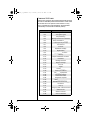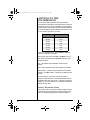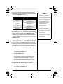
1
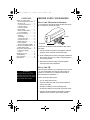
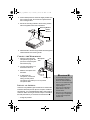
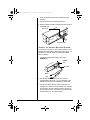
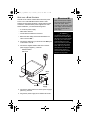
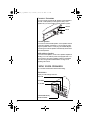
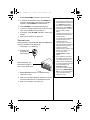
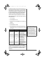
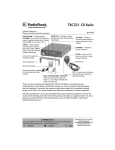
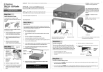
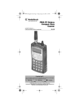
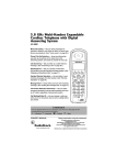
21-1576_rsj_012604.fm Page 1
Monday, January 26, 2004
www.radioshack.comSM
11:39 AM
Deluxe Chrome-Faced
40-Channel Mobile CB
with Weather Alert
OWNER’S MANUAL —
Please read before using this equipment.
21-1576
CH9/NOR/CH19 (Page 6)
S/RF/SWR/CAL (Page 10)
CB/WX/PA (Page 6)
Signal Meter (Page 10)
NB/OFF/MON (Page 10)
Microphone Jack
DUAL/OFF (Page 7)
UP/DN (Page 6)
Microphone
MIC GAIN (Page 7/
13)
OFF/VOLUME
Rotate to tune to
a channel
SQUELCH (Page 6)
RF GAIN (Page 6)
SWR CAL (Page
10)
Mounting Bracket
Mounting hardware
Microphone Holder and
mounting hardware
DC Cable
Thank you for purchasing the RadioShack 40-Channel Mobile CB with Weather Alert. It
provides for communication on the citizen’s radio band, lets you tune to local and national
weather service broadcasts, and lets you connect an optional PA speaker to use the public
address function. You can monitor the sound of CB or weather alert over a PA system while in
PA monitor mode. It has the maximum legal power output for the greatest available range, and
a built-in PLL (phase-locked loop) frequency synthesizer provides consistent, exact tuning.
CB radio provides hours of fun and entertainment! Listen and talk to people from all over the
country while traveling, and make new friends along routes that you regularly travel. It is also a
great way to keep informed of local emergencies, such as traffic accidents, road blocks,
weather alerts and so on.
! IMPORTANT !
© 2004 RadioShack Corporation.
If an icon appears at the end of a paragraph, go to the box on that page
with the corresponding icon for pertinent information.
o — Warning
— Caution
Ô — Note
All Rights Reserved.
RadioShack and RadioShack.com
are trademarks used by
RadioShack Corporation.
21-1576_rsj_012604.fm Page 2
Monday, January 26, 2004
CONTENTS
Before Using Your Radio ............ 2
Mount the Microphone Holder 2
Mount the CB .......................... 2
Connect the Microphone ......... 3
Install an Antenna ................... 3
Connect to Vehicle
Battery Power ......................... 4
Setup as a Base Station ......... 5
Connect Speakers .................. 6
Using Your CB Radio ................. 6
Receiving ................................ 6
Transmitting ............................ 7
Common 10-Codes ................. 8
CB Operation Tips .................. 9
Maximum Range ..................... 9
Reducing Noise .................... 10
Standing Wave Ratio (SWR) . 10
Listening to the Weather Band . 12
Digital Weather Alert ............. 12
Using Public Address Mode ..... 13
Using the PA Monitor
Function ................................. 13
Replacing the Fuse .................. 14
Troubleshooting ....................... 15
FCC Information ....................... 15
Specifications ........................... 16
11:39 AM
BEFORE USING YOUR RADIO
MOUNT THE MICROPHONE HOLDER
You can attach the microphone holder to either side of the
CB, horizontally or vertically as shown.
Vertical
Horizontal
To attach the microphone holder somewhere else, follow
these steps.
1. Use the microphone holder as a template to mark the
positions for the screws at the desired location.
2. At the marked positions, drill a hole slightly smaller than
the mounting screws. Do not drill into anything behind
the mounting surface.
3. Attach the microphone holder using the supplied
machine screws and lockwashers.
MOUNT THE CB
o
WARNING
o
Mount the CB securely to avoid
damage to the CB or vehicle, and to
avoid injury to anyone in the vehicle
during sudden starts or stops.
Find a convenient location in your vehicle to mount your CB.
If you are uncomfortable mounting the CB yourself, we
suggest you consult with your vehicle service center or
automotive dealer for assistance.
o
Select a mounting location where:
• you can easily reach the CB.
• wires and cables are clear of the vehicle’s pedals or
other moving parts.
• the CB is not directly in front of heating vents.
• all wires and cables can reach their connection points.
1. Use the mounting bracket as a template to mark the
positions for the screws on the mounting surface.
2
21-1576_rsj_012604.fm Page 3
Monday, January 26, 2004
11:39 AM
2. At the marked positions, drill a hole slightly smaller than
the mounting screws. Do not drill into objects behind
the mounting surface.
3. Secure the mounting bracket to the mounting surface
with the supplied screws and lockwashers.
Mounting Bracket
Rubber
Washers
Mounting
Knobs
4. Attach the CB to the mounting bracket with the supplied
rubber washers and mounting knobs.
CONNECT THE MICROPHONE
1. Align the holes inside the
microphone’s plug with the
pins in the microphone jack
and insert the plug.
Microphone
Jack
2. Turn the plug’s locking nut
clockwise to secure it.
3. Slide the microphone onto
the holder.
4. To disconnect the
microphone, unscrew the
Locking Nut
locking nut and pull the
microphone plug toward you. Do not pull the
microphone cable.
INSTALL AN ANTENNA
There are many different types of antennas for mobile CBs.
Dual band antennas provide optimum reception of CB and
WX channels. Your local RadioShack sells a wide variety of
antennas. When choosing an antenna, keep in mind that for
the best performance you should mount the antenna: • as high as possible.
CAUTION • To prevent damage to your CB,
do not attempt to transmit
without an antenna attached.
• Do not run the cable over sharp
edges or moving parts that
might damage it.
• Do not run the cable next to
power cables or other CB
antenna cables.
• Do not run the cable through a
vehicle's engine compartment
or other areas that produce
extreme heat.
3
21-1576_rsj_012604.fm Page 4
Monday, January 26, 2004
11:39 AM
• as far as possible from sources of electrical noise.
• vertically.
1. Follow the antenna’s mounting instructions.
2. Route the antenna cable to the CB radio and connect it
to the ANT. jack.
ANT. Jack
Antenna Cable
CONNECT TO VEHICLE BATTERY POWER
You can power your CB from your vehicle's battery or from
a standard AC outlet with an optional DC power supply. For
instructions on using AC power, see “Setup as a Base
Station” on Page 5.
1. Connect the supplied DC cable to the radio’s
POWER jack.
POWER
Jack
DC cable
Black
Red
2. Connect the cable’s black wire to your vehicle’s
negative battery terminal (–), or to a metal part of the
vehicle’s frame that is not insulated by a plastic part.
3. Connect the cable’s red wire (with in-line fuse) to a
voltage source that turns on and off with your vehicle’s
ignition switch, such as a spare accessory terminal in
your vehicle’s fuse box. This assures you that the CB is
turned off when you turn off the igntion.
4
21-1576_rsj_012604.fm Page 5
Monday, January 26, 2004
11:39 AM
SETUP AS A BASE STATION
This CB can be used as a base station with a DC power
source. Your local RadioShack store carries a wide
selection of base station antennas, coaxial antenna cable,
connectors, and base station power supplies. For base
station installation, you need the following items:
• a 12-volt DC power supply.
• base station antenna.
CAUTION Most 12-volt DC power supplies
plug into a standard AC outlet to
produce DC power. Before
connecting your CB to a 12-volt DC
power supply, read and follow the
instructions included with the
power supply.
o
• coaxial antenna cable and connectors.
1. Mount the base station antenna as described in its
owner’s manual. o
2. Connect the cable from your antenna to the ANT. jack
on the back of the CB.
3. Connect the supplied cable’s black wire to the DC
power supply’s negative (–) terminal.
Antenna cable to
ANT. Jack
WARNING
o
Use extreme caution when you
install or remove a base station
CB antenna. If the antenna starts
to fall, let it go! It could contact
overhead power lines. If the
antenna touches the power line,
your contact with the antenna,
mast, cable, or guy wires can
cause electrocution and death.
Call the power company to
remove the antenna. DO NOT
attempt to do so yourself.
Black
Wire
Red Wire
DC Power
Supply
4. Connect the cable’s red wire to the DC power supply’s
positive (+) terminal.
5. Plug the DC power supply into a standard AC outlet.
5
21-1576_rsj_012604.fm Page 6
Monday, January 26, 2004
11:39 AM
CONNECT SPEAKERS
You can connect an external CB speaker or PA speaker to
your CB. A CB speaker provides greater clarity. A PA
speaker lets you use the CB as a public-address system.
EXT SP
PA SP
External Speaker
To connect an external CB speaker, use a speaker rated at
8-ohms and capable of handling 5 or more watts of power.
Plug the speaker cable's 1/8-inch plug into the EXT SP jack.
Connecting the external speaker automatically disconnects
the internal speaker.
Public Address Speaker
To connect a PA speaker, use an 8-ohm speaker capable of
handling 5 or more watts of power and equipped with a 1/8inch connector. Plug the PA speaker cable into the PA SP
jack. See “Using Public Address Mode” on Page 13 for
operating instructions.
USING YOUR CB RADIO
Try to receive transmissions before transmitting.
RECEIVING
Adjust your CB settings as shown.
Set to CB.
Set to S/RF.
Set to NOR.
Rotate SQUELCH fully
counterclockwise.
6
21-1576_rsj_012604.fm Page 7
Monday, January 26, 2004
11:39 AM
1. Rotate OFF/VOLUME clockwise to turn on the CB.
2. To decrease CB sensitivity, slowly rotate SQUELCH
clockwise until the hissing sound stops. To increase
sensitivity, rotate SQUELCH counterclockwise. Ô
3. Adjust VOLUME to a comfortable listening level.
4. To tune to a channel, rotate the knob on the front of the
radio, or press UP/DN on the microphone. Ô
5. If necessary, rotate RF GAIN clockwise to boost signal
strength.
6. When you are finished, turn off the CB.
TRANSMITTING
Before transmitting, adjust CB, S/RF, NOR, and SQUELCH to
match the illustration under “Receiving” .
1. Follow steps 1-3 in “Receiving”. Ô
2. Hold down PTT
and speak into
the microphone.
Ô NOTE Ô
• If the CB picks up partial or very
weak transmissions, continue to
turn SQUELCH clockwise to
decrease the CB's sensitivity to
these signals. Turn SQUELCH
counterclockwise if you want to
listen to a weak or distant
station.
• Selecting either Channel 9 or 19
overrides the manual channel
selection control.
• All channels, with the exception
of Channels 9 and 19, are
available for general
communications. Channels 9
and 19 are reserved for motorist
assistance and for reporting
emergency situations,
hazardous road conditions, and
the like. To quickly tune to
Channel 9 or 19, set
CH9/NOR/CH19 to CH9 or
CH19.
• Do not speak too loudly when
transmitting. It does not make
your signal any stronger, and
might distort your transmission.
While transmitting, your
transmission strength is
shown on the signal meter.
3. Rotate MIC GAIN clockwise or counterclockwise to
adjust the mic gain.
• If you want to monitor Channel 9
during CB operation, set
DUAL/OFF to DUAL.
• If you hear a low-level poppingtype noise, set NB/OFF/MON to
NB to turn on the noise blanking
circuit. This helps minimize
background noise.
4. When you are finished speaking, release PTT. The CB
can receive transmissions on the selected channel.
5. When you are finished, turn off the CB.
7
21-1576_rsj_012604.fm Page 8
Monday, January 26, 2004
11:39 AM
COMMON 10-CODES
Citizen's band operators have largely adopted the following
10-codes for standard questions and answers. These codes
permit faster and more precise communication in noisy
areas. This table lists codes adopted by the Associated
Public-Safety Communications Officers (APCO).
Code
8
Meaning
10-1
Your signal is bad.
10-2
Your signal is good.
10-3
Stop transmitting.
10-4
Message received and understood.
10-5
Relay information to ______.
10-6
I am busy or are you busy?
10-7
Out of service.
10-8
In service.
10-9
Repeat last message.
10-10
Negative (NO).
10-11
____________in service.
10-12
Stand by.
10-13
Report road/weather conditions.
10-14
Information.
10-15
Message delivered.
10-16
Reply to message.
10-17
En route.
10-18
Urgent
10-19
Contact_______
10-20
What's your location?
10-21
Call______by telephone.
10-22
Cancel last message.
10-23
Arrived at the scene.
10-24
Assignment complete.
10-25
Meet______________.
10-26
Estimated time of arrival is___
10-30
Use caution.
10-31
Pick up.
10-33
Emergency traffic. Clear the channel
10-34
What time is it?
10-41
Switch to Channel -
10-62
Cannot understand.
21-1576_rsj_012604.fm Page 9
Monday, January 26, 2004
11:39 AM
CB OPERATION TIPS
Business
• Truck drivers and delivery personnel can learn road
and traffic conditions and get assistance in locating
destinations. A CB is also good company on long road
trips.
• On construction crews, a CB quickly pays for itself
when you are calling for additional materials or
coordinating the activities of different work crews.
• For security officers, a CB is more than a convenience
— it is a must for both safety and efficiency.
Personal
• If you are a two-car (or more) family, CBs are great for
communicating with family members while they are in
their cars.
• Contact friends or neighbors. Find out “what’s
happening” or plan a get-together.
• Ever have car trouble or run out of gas on the highway?
What an assurance it is to be able to call for assistance!
• Camping, fishing, and other sports are more fun with a
CB. Locate a buddy or find out “what’s cooking” back at
camp.
Transmission Courtesy
• Wait for a pause in someone else’s transmission before
you ask for a break.
• If you do not receive an answer to your call after a
second attempt, sign off and wait several minutes
before trying again.
• Do not hold down PTT when you are not talking. (This is
called dead keying.)
• Assist callers with directions, information about road
conditions, and any other reasonable request.
MAXIMUM RANGE
The maximum range and quality of CB transmissions vary
depending on the following typical conditions:
• The type and quality of antenna used.
• The height of the antenna's mounting location - the
higher the antenna, the greater the signal's range.
• The surrounding terrain - mountains and tall buildings.
limit the range.
• Weather conditions.
9
21-1576_rsj_012604.fm Page 10 Monday, January 26, 2004
11:39 AM
• The number of nearby CBs operating on the same
channel.
• standing wave ratio (SWR) between the antenna and
the CB.
REDUCING NOISE
Because your CB is exceptionally quiet, any noise you hear
is probably from an external source in your vehicle, such as
the alternator, another radio, or spark plugs. Your CB has a
noise blanking (NB) circuit to keep background noise to a
minimum. However, strong sources of electrical noise,
generated by spark plugs or the ignition of your car, or
another radio, might be more than the circuit can
compensate for. If you suspect engine noise as a source,
turn off the engine and operate the CB with the ignition set
to ACC. If most or all of the noise stops, the problem is in
the vehicle's ignition or electrical system.
These hints may help reduce or eliminate such noise.
• Replace old ignition wires with new, high-voltage,
noise-suppression wires.
• Install noise suppressors on your spark plugs, or install
new spark plugs that have built-in suppressors.
• Be sure that the black wire ground connection is
securely attached to your vehicle's battery's negative
(GND) terminal or to a good electrical chassis ground.
• If problems persist, check your alternator or generator,
voltage regulator, and any stand-alone gauges. Noise
from these sources can be reduced or eliminated using
bypass capacitors at various output voltage points.
STANDING WAVE RATIO (SWR)
Most antennas are factory adjusted. However, you can
usually improve antenna performance by matching its
characteristics to the CB's RF output power. The built-in
SWR meter enables you to do this. The impedance of a
CB's output compared to the impedance of the antenna is
usually slightly mismatched. By adjusting this impedance
ratio to be as close to 1:1 as possible, you maximize the
efficiency of your system.
10
21-1576_rsj_012604.fm Page 11 Monday, January 26, 2004
11:39 AM
The SWR value takes into account the actual frequency of
the RF signal transmitted. Therefore, you will get a different
SWR reading from one CB channel to another. Almost all
CB transmissions fall within an acceptable range. However,
for optimum radio performance, we recommend that you
fine tune the antenna's system based on the channel you
use most. If you have no channel preference, set your
antenna's SWR for maximum performance on Channel 19.
After installing the antenna, follow these steps to adjust the
standing wave ratio.
1. Turn on the CB.
2. Set S/RF/SWR/CAL to CAL.
3. Hold down PTT and rotate SWR CAL so the meter points
to CALd.
4. Release PTT.
5. Set S/RF/SWR/CAL to SWR.
6. Press PTT again and note the actual measurement on
the SWR scale. Refer to the following table to interpret
the reading.Ô
Ratio
1:1 - 1.5:1
1.5:1 - 2:1
2:1 - 3:1
Higher than 3.1:1
Rating
Evaluation
Superior
Perfect match between
the antenna/cable and the
RF output of the CB.
Excellent
The antenna/cable
system is an outstanding
match to the transmitter's
RF output. Ideal for most
CB installations.
Good
The antenna/cable
system will perform to
specification under most
normal conditions.
Inefficient
Indicates a need to
inspect the system, the
mounting of the antenna
and all pertinent
hardware.
Ô NOTE Ô
Prolonged exposure to salt spray,
humidity, weather-induced
corrosion, or vehicle vibration can
cause antenna performance to
degrade with a subsequent rise in
the SWR. Anytime you notice that
the SWR reading is greater than
3:1, check the condition of the
antenna, the antenna cable, and all
antenna connectors and hardware.
The ideal standing wave ratio (SWR) is 1:1, or a meter
reading of 1 on the SWR meter's top scale. This reading can
only be obtained under laboratory conditions. A SWR ratio
of 1.5:1 to 2:1 is excellent for most mobile CB antenna
applications.
11
21-1576_rsj_012604.fm Page 12 Monday, January 26, 2004
11:39 AM
LISTENING TO THE
WEATHER BAND
Your CB comes preprogrammed with seven weather
channels that are allocated by the Federal Communications
Commission (FCC) for use by the National Oceanographic
and Atmospheric Administration (NOAA). NOAA broadcasts
your local forecast and regional weather information on one
or more of these channels in your area:
Frequency (MHz)
Channel
162.400
WX1
162.425
WX2
162.450
WX3
162.475
WX4
162.500
WX5
162.525
WX6
162.550
WX7
To listen to a weather station, slide CB/WX/PA to WX and
select one of the above channels.
When the CB radio is set to CB, WX or PA (MON), and you
enter a NOAA broadcast area, WX/ALERT indicates three
possible situations:
OFF — No weather signal detected. Check another
channel.
RED — Normal weather signal. No emergency broadcast.
Flashing RED — Weather alert broadcast on the selected
channel. Turn to WX to listen, or press PTT or UP/DN to clear
the alert.
To verify reception, your radio must receive a test or
emergency alert broadcast. The National Weather Service
broadcasts a test alert every week. To find the specific test
schedule in your area, contact your local NOAA or National
Weather Service office.
DIGITAL WEATHER ALERT
When in CB mode, the radio automatically sounds an alert if
a weather alert signal is detected. This is especially useful
when your area is expecting severe weather conditions.
12
21-1576_rsj_012604.fm Page 13 Monday, January 26, 2004
11:39 AM
When your local weather station broadcasts a severe
weather alert, the CB sounds a tone corresponding to the
alert type and WX/ALERT flashes.Ô
Alert Type
You Hear
Ô NOTE Ô
• Because of atmospheric
conditions, sometimes the
signal your radio received might
not contain information relevant
to the emergency level of the
alert.
Warning or Emergency
Continuous short beeps
Watch
Three short beeps and a 2 second
pause (repeats)
Advisory
Two short beeps and a 2 second
pause (repeats)
• The radio sounds an alert
regardless of the channel
setting in CB mode.
Test
One short beep and a 3 second
pause (repeats)
• The CB does not sound alerts
while you transmit.
EAT (Emergency Action
Termination)
One short beep and a 3 second
pause (repeats) Ô
• If you are in a rural or fringe
area, your radio might be
triggered by an alert broadcast
in one area, but not be triggered
if you travel to another area
(even close by).
To silence the alert tones, press PTT or UP/DN. WX/ALERT
stops flashing. If the radio receives a new digital weather
alert, the radio sounds that alert and WX/ALERT flashes
according to the emergency level encoded in the signal.
To hear the weather alert broadcast when it is received, set
CB/WX/PA to WX.
• The CB radio receives the
digital weather alert codes and
sounds alert tones in PA CB
monitor mode.
USING PUBLIC ADDRESS MODE
You can connect a PA speaker so that you can use the
public address function. You can also hear the sound of CB
or weather alert through the PA speaker by turning on the
PA monitor function. See “Connect Speakers” on Page 6.
1. Adjust OFF/VOLUME to the minimum listening level.
2. Set CB/WX/PA to PA . PA appears on the display. The
signal meter and TX/RX turn off.
3. Set NB/OFF/MON to OFF.
4. Hold down PTT and speak into the microphone. Be sure
the microphone is as far from the PA speaker as
possible to reduce audio feedback or “howling”.
5. Adjust MIC GAIN as needed to set the PA's volume.
USING THE PA MONITOR FUNCTION
1. Adjust OFF/VOLUME to the minimum listening level.Ô
2. Set CB/WX/PA to PA . PA appears on the display. The
signal meter and TX/RX turn off.
13
21-1576_rsj_012604.fm Page 14 Monday, January 26, 2004
11:39 AM
3. Set NB/OFF/MON to MON. This indicates you are
monitoring a CB channel over a PA system.
4. Rotate the knob on the front of the radio or press
UP/DN on the microphone to change the channel.
REPLACING THE FUSE
The CB’s in-line fuse protects it from power surges and
short circuits. When replacement is required, use a 2-amp,
fast-acting glass fuse, available at your local RadioShack.
1. Make sure your vehicle and CB are turned off.
2. Push the fuse holder ends together. Then, turn either
end counterclockwise and pull them apart.
Fuse Holders
Fuse
3. Remove the old fuse and insert a new fuse of the same
type and rating.
4. Push the fuse holder ends together and twist one end
clockwise.
14
21-1576_rsj_012604.fm Page 15 Monday, January 26, 2004
11:39 AM
TROUBLESHOOTING
If your CB is not working as it should, follow the suggestions
below to see if you can eliminate the problem. If the problem
persists, take your CB to a RadioShack store for assistance.
Symptom
Trouble receiving.
Trouble transmitting.
Possible Causes
Make sure the CB is turned on.
Make sure SQUELCH is adjusted properly.
Be sure RF GAIN is fully clockwise.
Make sure the CB is set to an operating
channel.
Make sure the microphone is securely
connected.
Check for a good antenna connection.
Make sure the antenna cable is securely
connected to the radio.
Make sure the antenna is fully extended.
Make sure all connections are secure and
free of corrosion.
Make sure CB/WX/PA is set to CB.
No channel selection,
or only Channel 9 or
19 can be selected.
Make sure CB/WX/PA is set to CB.
Set CH9/NOR/CH19 to NOR.
The CB is completely
inoperable.
Check the DC cord and in-line fuse.
Replace the fuse. See “Replacing the Fuse”
on Page 14.
FCC INFORMATION
The Federal Communications Commission (FCC) does not require
you to have a license to operate this CB. However, the FCC does
require that you read and know Part 95 of FCC Rules. These rules
apply to the operation of a Class D CB.
o
Your CB might cause TV or radio interference even when it is
operating properly. To determine whether your CB is causing the
interference, turn off your CB. If the interference goes away, your
CB is causing it. Try to eliminate the interference by:
• moving your CB away from the receiver
• connecting your CB to an outlet that is on a different electrical
circuit from the receiver
Ô NOTE Ô
Care
Keep your CB dry; if it gets wet,
wipe it dry immediately. Use and
store the CB only in room
temperature environments. If used
in a boat, select a location for the
CB so that it is unlikely to get wet.
Handle the CB carefully; do not
drop it. Keep the CB away from
dust and dirt, and wipe it with a
damp cloth occasionally to keep it
looking new.
Service and Repair
If your CB is not performing as it
should, take it to a RadioShack
store for assistance. To locate your
nearest RadioShack, use the store
locator feature on RadioShack's
website (www.radioshack.com), or
call 1-800-The Shack (843-7422)
and follow the menu options.
Modifying or tampering with your
CB's internal components can
cause a malfunction and might
invalidate its warranty and void
your FCC authorization to operate
it.
o
WARNING
o
Do not open your CB to make any
internal adjustments. Any internal
adjustments can be made only by
an authorized service technician.
Unauthorized internal adjustments
and/or modifications can lead to
illegal operation as defined by Part
95 of FCC Rules.
• contacting your local RadioShack store for help
• If you cannot eliminate the interference, the FCC requires that
you stop using your CB.
This device complies with Part 15 of the FCC Rules. Operation is
subject to the following two conditions: (1) this device may not
cause harmful interference, and (2) this device must accept any
interference received, including interference that may cause
undesired operation.
15
21-1576_rsj_012604.fm Page 16 Monday, January 26, 2004
11:39 AM
SPECIFICATIONS
GENERAL
Channels .......................................................................................................................................... 40 Channels
Frequency Range ..................................................................................................... 26.965 MHz to 27.405 MHz
Power Requirements .................................................................. 13.8V DC, (12-16 Volts DC, Negative Ground)
Dimensions (HWD) ..................................................................... 21/4 × 71/4 × 87/8 Inches, (57 × 185 × 225 mm)
Weight ........................................................................................................................................... 3.1 lbs (1.4 kg)
RECEIVER
Sensitivity ........................................................................................................... 1 µV or better for 10 dB (S+N)/N
Adjacent Channel Rejection ....................................................................................................... 50 dB (at 10 kHz)
Audio Output ........................................................................................................................ 4.5 Watts (Maximum)
Frequency Response ........................................................................................................................ 450-2500 Hz
Intermediate Frequency .............................................................................. 1st IF: 10.695 MHz, 2nd IF: 455 KHz
Cross Modulation ......................................................................................................................................... 35 dB
Squelch ................................................................................................................ Adjustable from 0.5 µV to 1 mV
TRANSMITTER
Output Power ................................................................................................................. 4 Watts (FCC Maximum)
Type of Modulation ........................................................................ AM Double-Sideband, Full Carrier Modulation
Modulation Capability ................................................................................................................................... ±90%
Spurious Emission ..................................................................................................................... Less than –70 dB
Frequency Tolerance ............................................................................................................................... ±200 Hz
Antenna Impedance .................................................................................................................................. 50 Ohm
Current Drain (13.8-volt supply) ................................ 1 Amp with No Modulation, 1.6 Amps with 80% Modulation
PUBLIC ADDRESS
Output Power ....................................................................................................................... 4.5 Watts (Maximum)
Current Drain (at maximum power) ....................................................................................................... 1.2 Amps
WEATHER RADIO
Frequency Coverage (MHz) ...................................................................... 162.400 through 162.550 (7 channels)
Limited Ninety-Day Warranty
This product is warranted by RadioShack against manufacturing defects in material and workmanship under normal use for ninety (90)
days from the date of purchase from RadioShack company-owned stores and authorized RadioShack franchisees and dealers. EXCEPT
AS PROVIDED HEREIN, RadioShack MAKES NO EXPRESS WARRANTIES AND ANY IMPLIED WARRANTIES, INCLUDING THOSE
OF MERCHANTABILITY AND FITNESS FOR A PARTICULAR PURPOSE, ARE LIMITED IN DURATION TO THE DURATION OF THE
WRITTEN LIMITED WARRANTIES CONTAINED HEREIN. EXCEPT AS PROVIDED HEREIN, RadioShack SHALL HAVE NO LIABILITY
OR RESPONSIBILITY TO CUSTOMER OR ANY OTHER PERSON OR ENTITY WITH RESPECT TO ANY LIABILITY, LOSS OR DAMAGE CAUSED DIRECTLY OR INDIRECTLY BY USE OR PERFORMANCE OF THE PRODUCT OR ARISING OUT OF ANY BREACH
OF THIS WARRANTY, INCLUDING, BUT NOT LIMITED TO, ANY DAMAGES RESULTING FROM INCONVENIENCE, LOSS OF TIME,
DATA, PROPERTY, REVENUE, OR PROFIT OR ANY INDIRECT, SPECIAL, INCIDENTAL, OR CONSEQUENTIAL DAMAGES, EVEN IF
RadioShack HAS BEEN ADVISED OF THE POSSIBILITY OF SUCH DAMAGES.
Some states do not allow limitations on how long an implied warranty lasts or the exclusion or limitation of incidental or consequential
damages, so the above limitations or exclusions may not apply to you.
In the event of a product defect during the warranty period, take the product and the RadioShack sales receipt as proof of purchase date
to any RadioShack store. RadioShack will, at its option, unless otherwise provided by law: (a) correct the defect by product repair without
charge for parts and labor; (b) replace the product with one of the same or similar design; or (c) refund the purchase price. All replaced
parts and products, and products on which a refund is made, become the property of RadioShack. New or reconditioned parts and products may be used in the performance of warranty service. Repaired or replaced parts and products are warranted for the remainder of the
original warranty period. You will be charged for repair or replacement of the product made after the expiration of the warranty period.
This warranty does not cover: (a) damage or failure caused by or attributable to acts of God, abuse, accident, misuse, improper or abnormal usage, failure to follow instructions, improper installation or maintenance, alteration, lightning or other incidence of excess voltage or
current; (b) any repairs other than those provided by a RadioShack Authorized Service Facility; (c) consumables such as fuses or batteries; (d) cosmetic damage; (e) transportation, shipping or insurance costs; or (f) costs of product removal, installation, set-up service adjustment or reinstallation.
This warranty gives you specific legal rights, and you may also have other rights which vary from state to state.
RadioShack Customer Relations, 200 Taylor Street, 6th Floor, Fort Worth, TX 76102
12/99
01A04
Printed in China
21-1576
UTZZ01367ZZ