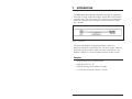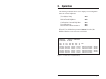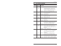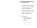
1
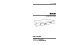
WTI Part No.: 12548
Rev. F
RMM
Rack Mount Data/Fax Modem
User's Guide
5 Sterling · Irvine · California 92618-2517
(949) 586-9950 · Toll Free: 1-800-854-7226
Fax: (949) 583-9514 · http://www.wti.com
1. Introduction
The RMM Rack Mount Data/Fax Modem is designed for applications
that require a single “Industrial Strength” modem that easily installs in
equipment bays. The unit requires only 1 rack space, thus eliminating
the hassle of equipment trays and power bricks required for “Plastic
Box” modems.
Figure 1: Front Panel
The heart of the RMM is the popular and highly reliable U.S.
Robotics® Sportster® 28.8 modem card. The power supply is filtered,
fused and surge protected for operation in harsh environments. The
RMM is available in 115/230 (switchable) and 48 volt DC versions.
Features
·
·
·
·
Requires Only One 19 Inch Rack Unit.
High Speed ITU-T V.34+
Filtered and Surge Protected Power Supply.
115/220 Volt AC and 48 Volts DC Versions.
Page 1
RMM User’s Guide
2. Unit Description
2.1. Front Panel Indicators
LED
AA
(Auto Answer)
CD
(Carrier Detect)
Status
On
Off
Flash
On
RD
(Receive Data)
SD
(Send Data)
TR
(Data Terminal
Ready)
Flash
CS
(Clear to Send)
On
Page 2
Flash
On
Meaning
Answer mode only: Modem is answering a call and
DIP Switch 5 is UP (Enable Auto Answer), or
register S0 is set to 1 (Auto Answer, 1 Ring).
No activity, or modem is originating a call.
Incoming call.
A valid data carrier signal has been received from a
remote modem, and Dip Switch 6 is UP (Normal
Carrier Detect). Modem is ready to transmit data.
The CD Indicator will remain ON constantly if Dip
Switch 6 is DOWN (Carrier Detect Override).
Modem is sending result codes or passing received
data bits.
Computer is sending data bits.
Modem is receiving DTR signal from computer. The
TR indicator will only function when Dip Switch 1 is
UP (Normal DTR). Remains ON constantly if Dip
Switch 1 is DOWN (DTR Override).
Hardware flow control is enabled (&H1, &H3),
modem is waiting for low CTS signal.
3. Operation
The following commands can be used to display current configuration
status and various help menus:
ATI4
AT$
ATD$
AT&$
ATS$
ATZ3
View Modem Setup:
Basic Help Menu:
Dial Command Help Menu:
Configuration Command Help Menu:
List of S-Registers:
Reset Modem to Default Profile 0:
When the View Modem Setup command (ATI4) is invoked, the
RMM will display a status screen as shown below.
B0 E1 F1
BAUD=9600
DIAL=PULSE
&A1
&M4
&B0
&N0
S00=001
S07=060
S14=000
S21=010
S28=008
S35=000
M1 Q0 V1 X1 Y0
PARITY=N WORDLEN=8
ON HOOK
&C1
&P0
&D2
&R1
S01=000
S08=002
S15=000
S22=017
S29=020
S36=014
&G0
&S0
&H0
&T5
S02=043
S09=006
S16=000
S23=019
S30=000
S37=000
&I0
&Y1
S03=013
S10=007
S17=000
S24=000
S31=000
S38=000
&K1
S04=010
S11=070
S18=000
S25=005
S32=000
S44=015
S05=008
S12=050
S19=000
S26=000
S33=000
S51=000
S06=002
S13=000
S20=000
S27=000
S34=006
Figure 2: The Status Screen (Defaults Shown)
Page 3
RMM User’s Guide
4. Installation
4.1. 48 Volt DC Power Option
The 48 Volt DC input is not polarity sensitive. Therefore, you can
connect either positive or negative wires from your 48 volt power
source to either input and the internal circuitry will adjust for the proper
polarity.
Input Range: 40 - 60 Volts DC, 200 milliamps maximum.
Figure 3: 48 Volt DC Power Option
Page 4
Installation
4.2. Dip Switch Settings
Switch
Factory
Setting
1
Function
Data Terminal Ready (DTR) Override
l
2
l
3
l
4
l
5
l
6
l
7
l
8
l
UP
Normal DTR operations: Computer must
provide DTR signal for modem to accept
commands. Dropping DTR terminates call.
DOWN DTR Override: Modem ignores DTR
Verbal/Numeric Result Codes
UP
Verbal (Word) Results
DOWN Numeric Results
Result Code Display
UP
Suppress Result Codes
DOWN Display Result Codes
Command Mode Local Echo Suppression
UP
Enable Echo
DOWN Suppress Echo
Auto Answer Suppression
UP
Auto Answer On: Modem answers on first
ring, or higher if specified in NVRAM
DOWN Auto Answer Off: Disable auto answer
Carrier Detect (CD) Override
UP
Normal: Modem sends CD signal when
connecting with another modem, drops CD on
disconnect
DOWN Override: CD always ON
Power-On and ATZ Reset Software Defaults
UP
User Defaults: Load Y or Y1 configuration
from user-defined nonvolatile memory
(NVRAM).
DOWN Factory Defaults; Load &F0 (Generic)
template from read-only memory (ROM).
AT Command Set Recognition
UP
Dumb Mode: Disables command recognition
DOWN Smart Mode: Enables command recognition
Page 5
RMM User’s Guide
Page 6
Installation
5. Command Summary
· Type commands in either upper or lower case. Do not use a
·
·
·
·
combination of upper and lower case characters.
Use the Backspace key to delete errors. Note that the original AT
command is stored in the modem buffer, and cannot be deleted.
Some commands have numeric options. If these commands are
invoked without a numeric option, the modem will assume option
0 (zero). For example, when the command ATB is invoked, the
modem will assume command ATB0 was intended.
All commands begin with the AT prefix, and are invoked by
pressing [Enter] (Carriage Return). The only exceptions are the
A/ command (Repeat previous command) and +++ (Exit to online command mode).
The maximum command length is 40 characters. This does not
include the AT prefix, Carriage Returns, or spaces.
•
•
Note:
All defaults are based on the &F1-Hardware Flow
Control template loaded in NVRAM.
Defaults are marked with an asterisk (*).
Command
Function/Options
$
A
Displays basic command list (On-line Help Menu).
Manual Answer: goes off hook in answer mode.
Pressing any key aborts the operation.
Re-executes the last issued command. Used mainly
to redial. Does not require the AT prefix or a
Carriage Return.
Aborts off-hook dial/answer operation and hangs up.
Required prefix for all modem commands. Can also
be used to test for the “OK” result code.
Not required for the A/ command or +++ command.
U.S./ ITU-T answer sequence
* B0
ITU-T answer sequence
B1
U.S. answer tone
A/
Any key
AT
Bn
Page 7
RMM User’s Guide
Command
Function/Options
Dn
Dials the specified phone number.
Can also include the following command options:
L
Re-dials last number dialed
* P
Pulse (Rotary) Dial Mode
R
Originates call using answer (reverse)
frequencies.
Sn
Dials phone number string stored in NVRAM
at position n (n = 0-3). Phone numbers are
stored with the &Zn=s command.
T
Tone Dial Mode
,
(Comma) Two Second Pause. Comma
pause duration can be redefined via the
S8 Register.
;
(Semicolon) Return to Command mode
after dialing
“
Dials the letters that follow (in an
alphabetic phone number)
!
(Exclamation point) Flashes the
switch hook
/
Delays for 125 msec before proceeding
with dial string
W
Wait for second dial tone (X3 or higher).
Linked to S6 register
@
Dials, waits for 5 seconds of silence
after detecting ringbacks, and then
continues (X2 or X4).
$
Displays a list of dial commands.
Sets local echo. See DIP Switch 4 (Section 4.2).
E0
Echo OFF
* E1
Modem displays keyboard commands
Sets online local echo of transmitted data ON/OFF.
F0
Local echo ON. Modem sends a copy of
data it sends to the remote system to
your screen.
* F1
Local echo OFF. Receiving system may
send a remote echo of data it receives.
Controls ON/OFF hook.
H0
Hangs up (goes on hook)
H1
Goes off hook
En
Fn
Hn
Page 8
Command Summary
Command
Function/Options
In
Displays the following information.
I0
Four-digit product code
I1
Results of ROM checksum
I2
Results of RAM checksum
I3
Product type
I4
Current modem settings
I5
Nonvolatile memory (NVRAM) settings
I6
Link diagnostics
I7
Product configuration
Operates speaker.
M0
Speaker always OFF
* M1
Speaker ON until CONNECT
M2
Speaker always ON
M3
Speaker ON after dial, until CONNECT
Returns online.
O0
Returns online
O1
Returns online and retrains
Sets pulse dial (for phone lines that don’t support
touch-tone dialing).
Displays/suppresses result codes. See DIP Switch 3
(Section 4.2).
* Q0
Displays result codes
Q1
Quiet mode; no result codes
Q2
Displays result codes only in Originate
mode. Cannot be stored in NVRAM.
Sets bit .b of register r to value n (0/OFF or 1/ON).
Sets register r to value n. See list of S-register
settings (Section 6).
Displays contents of S-register r.
Displays a list of the S-Registers (Section 6).
Sets tone dial.
Displays verbal/numeric result codes. See DIP
Switch 2 (Section 4.2).
V0
Numeric codes
* VI
Verbal codes
Mn
On
P
Qn
Sr.b=n
Sr=n
Sr?
S$
T
Vn
Page 9
RMM User’s Guide
Command
Function/Options
Xn
Sets result code displayed. Default is X4.
Xn Setting
Result Codes
X0 X1 X2 X3
0/OK
•
•
•
•
1/CONNECT
•
•
•
•
2/RING
•
•
•
•
3/NO CARRIER
•
•
•
•
4/ERROR
•
•
•
•
5/CONNECT 1200
•
•
•
6/NO DIAL TONE
•
7/BUSY
•
8/NO ANSWER*
•
10/CONNECT 2400
•
•
•
13/CONNECT 9600
•
•
•
18/CONNECT 4800
•
•
•
20/CONNECT 7200
•
•
•
21/CONNECT 12000
•
•
•
25/CONNECT 14400
•
•
•
43/CONNECT 16800
•
•
•
85/CONNECT 19200
•
•
•
91/CONNECT 21600
•
•
•
99/CONNECT 24000
•
•
•
103/CONNECT 26400
•
•
•
107/CONNECT 28800
•
•
•
151/CONNECT 31200
•
•
•
155/CONNECT 33600
•
•
•
Functions
Adaptive Dialing
Wait for 2nd Dial Tone (W)
Wait for Answer (@)
Fast Dial
•
•
•
•
•
*Requires @ in dial string; replaces NO CARRIER
Yn
Page 10
Selects power-on/reset default configuration.
* Y0
Default is profile 0 setting in NVRAM
Y1
Default is profile 1 setting in NVRAM
X4
•
•
•
•
•
•
•
•
•
•
•
•
•
•
•
•
•
•
•
•
•
•
•
•
•
•
•
Command Summary
Command
Function/Options
Zn
Resets modem based on current DIP Switch settings.
Z0
Resets modem to NVRAM profile
selected by the Y command
Z1
Resets modem to NVRAM profile 0
Z2
Resets modem to NVRAM profile 1
Z3
Resets modem to factory default
profile 0 (&F0)
Z4
Resets modem to factory default
profile 1 (&F1)
Z5
Resets modem to factory default
profile 2 (&F2)
Displays a list of ampersand (&) commands.
Enables/disables additional result code subsets (see Xn).
&A0 ARQ result codes disabled
&A1 ARQ result codes enabled
&A2 V.32 modulation indicator added
* &A3 Protocol indicators addedLAPM/MNP/NONE (error control) and
V42BIS/MNP5 (data compression)
Manages modem's serial port rate.
&B0 Variable, follows connection rate
* &B1 Fixed serial port rate
&B2 Fixed in ARQ mode, variable in
non-ARQ mode
Controls Carrier Detect (CD) signal.
See DIP Switch 6 (Section 4.2).
&C0 CD override
* &C1 Normal CD operations
Controls Data Terminal Ready (DTR) operations.
See DIP Switch 1 (Section 4.2).
* &D0 DTR override
&D1 DTR toggle causes online
Command mode
&D2 Normal DTR operations
&D3 Resets on receipt of DTR
&$
&An
&Bn
&Cn
&Dn
Page 11
RMM User’s Guide
Command
Function/Options
&Fn
Loads a read-only (non-programmable)
factory configuration.
&F0
Generic template
* &F1
Hardware flow control template
&F2
Software flow control template
Sets Guard Tone.
* &G0 No guard tone (U.S. and Canada)
&G1 550 Hz guard tone (some European
countries), requires B0 setting.
&G2 1800 Hz guard tone (U.K.), requires
B0 setting.
Sets Transmit Data (TD) flow control
&H0 Flow control disabled
* &H1 Hardware flow control, Clear to
Send (CTS)
&H2 Software flow control, XON/XOFF
&H3 Hardware and software control
Sets Receive Data (RD) software flow control
(see also &Rn).
* &I0
Software flow control disabled
&I1
XON/XOFF signals to your modem and
remote system
&I2
XON/XOFF signals to your modem only
Enables/disables data compression.
&K0 Data compression disabled
* &K1 Auto enable/disable
&K2 Data compression enabled
&K3 MNP5 compression disabled
Sets Error Control (ARQ) for connections at 1200 bps
and higher.
&M0 Normal mode, error control disabled
&M1 Reserved
&M2 Reserved
&M3 Reserved
* &M4 Normal/ARQ
&M5 ARQ mode
&Gn
&Hn
&In
&Kn
&Mn
Page 12
Command Summary
Command
Function/Options
&Nn
Sets connect speed. If connection cannot be established
at this speed, the modem will hang up. Sets ceiling
connect speed if &Un is greater than 0 (See &Un).
* &N0 Variable rate
&N1 300 bps
&N2 1200 bps
&N3 2400 bps
&N4 4800 bps
&N5 7200 bps
&N6 9600 bps
&N7 12,000 bps
&N8 14,400 bps
&N9 16,800 bps
&N10 19,200 bps
&N11 21,600 bps
&N12 24,000 bps
&N13 26,400 bps
&N14 28,800 bps
&N15 31,200 bps
&N16 33,600 bps
Sets pulse (rotary) dial make/break ratio.
* &P0
U.S. /Canada ratio, 39% / 61%
&P1
U.K. ratio, 33 % / 67%
Sets Receive Data (RD) hardware flow control,
Request to Send (RTS) (see also &In).
&R0 Reserved
* &R1 Modem ignores RTS
&R2 Received Data to computer only on RTS
Controls Data Set Ready (DSR) operations.
* &S0
DSR override; always ON
&S1
Modem controls DSR
&Pn
&Rn
&Sn
Page 13
RMM User’s Guide
Command
Function/Options
&Tn
Begins test modes.
&T0
Ends Test in Progress
&T1
Analog Loopback
&T2
Reserved
&T3
Local Digital Loopback
&T4
Enables Remote Digital Loopback
* &T5
Prohibits Remote Digital Loopback
&T6
Initiates Remote Digital Loopback
&T7
Remote Digital with self test and
error detector
&T8
Analog Loopback with self test and
error detector
Sets floor connect speed when &Un is greater than 0.
&Nn is the ceiling connect speed (See &Nn).
* &U0 Disabled
&U1 300 bps
&U2 1200 bps
&U3 2400 bps
&U4 4800 bps
&U5 7200 bps
&U6 9600 bps
&U7 12,000 bps
&U8 14,400 bps
&U9 16,800 bps
&U10 19,200 bps
&U11 21,600 bps
&U12 24,000 bps
&U13 26,400 bps
&U14 28,800 bps
&U15 31,200 bps
&U16 33,600 bps
Writes current configuration to NVRAM templates.
&W0 Modifies the NVRAM 0 template (Y0)
&W1 Modifies the NVRAM 1 template (Y1)
Sets break handling.
&Y0 Destructive, but doesn't send break
* &Y1 Destructive, expedited
&Y2 Non-destructive, expedited
$Un
&Wn
&Yn
Page 14
Command
Function/Options
&Zn=s
Writes phone number s to NVRAM at position n
(n = 0-3).
Writes last executed dial string to NVRAM at
position n (n = 0-3).
Displays the phone number stored at position n
(n = 0-3).
Displays the last executed dial string.
Escapes to online-command mode.
&Zn=L
&Zn?
&ZL?
+++
Page 15
RMM User’s Guide
6. S-Registers
Note: To change a setting, use the ATSr=n command,
where r is the register and n is a decimal value from 0-255
(unless otherwise indicated).
Register
Default
S0
1
Sets the number of rings on which to answer in Auto
Answer Mode. When set to 0, Auto Answer is
disabled. See DIP Switch 5 (Section 4.2).
S1
0
Counts and stores the number of rings from an
incoming call. Register S0 must be greater than 0.
S2
43
Stores the ASCII decimal code for the escape code
character. The default character is +. A value of 128255 disables the escape code.
S3
13
Stores the ASCII code for the Carriage Return
character. Valid range is 0-127.
S4
10
Stores the ASCII decimal code for the Line Feed
character. Valid range is 0-127.
S5
8
Stores the ASCII decimal code for the Backspace
character. A value of 128-255 disables the Backspace
key's delete function.
S6
2
Sets the number of seconds the modem will wait
before dialing. If Xn is set to X2 or X4, S6
determines the timeout length when no dial tone is
detected.
S7
60
Sets the number of seconds the modem will wait for a
carrier. Often used to select a longer duration when
the modem is originating an international connection.
S8
2
Sets the duration (in seconds) for the Dial command
pause option (,).
S9
6
Determines the length of time (in tenths of a second)
the remote modem’s carrier signal must continue in
order to be recognized by the RMM.
S10
7
Sets the length of time (in tenths of a second) the
modem will wait after loss of carrier before hanging
up. Allows the modem to distinguish between a line
hit (or other momentary break) from a true disconnect
(hang up) by the remote modem.
Page 16
Function
S-Registers
Register
S10
(continued)
Default
Function
Although it is not recommended to connect to a line
with call waiting, the S10 register can be adjusted
upward to prevent the modem from misinterpreting
the second call signal as a remote disconnect. If call
waiting is a problem, it is preferable to contact your
phone company to determine the command to
temporarily disable call waiting (typically *70W).
For example: ATDT *70W phone number.
Note: If S10 = 255, the modem will not hang up
when the carrier is lost. Dropping DTR hangs up the
modem.
S11
70
Sets the duration and spacing (in milliseconds) for
tone dialing.
S12
50
Sets the duration (in fiftieths of a second) of the guard
time for the escape code sequence (+++).
S13
0
Bit-mapped register. Select the bit(s) you want on
and set S13 to the total of the values in the Value
Column. For example, ATS13=17 enables bit 0
(value is 1) and bit 4 (value is 16).
Bit
Value
Result
0
1
Reset when DTR drops.
1
2
Reset non-MNP transmit buffer
from 1.5K to 128 bytes.*
2
4
Set backspace key to delete.
3
8
On DTR signal, autodial the
number stored in NVRAM at
position 0.
4
16
At Power On/Reset, autodial the
number stored in NVRAM at
position 0.
5
32
Reserved
6
64
Reserved
7
128
Disconnect on escape code.
* The 1.5K-byte non-ARQ buffer allows data transfer with Xmodem and Ymodem
type file transfer protocols without using flow control.
The 128 Byte option allows remote users with slower modems to prevent
transmitted data from scrolling off screen. When a remote user sends an XOFF
(Ctrl-S) to your computer and transmission stops, data in transit from your modem's
buffer does not exceed the size of the remote user's screen. This is also helpful
when a remote modem/printer application is losing characters.
Page 17
RMM User’s Guide
Register
Default
S14
0
Reserved
S15
0
Bit-mapped register setup. To set the register, see
instructions for S13.
Value
Result
Bit
0
1
Disable ARQ/MNP for V.22.
1
2
Disable ARQ/MNP for .22bis.
2
4
Disable ARQ/MNP V.32 / V.32bis
/ V.32terbo.
3
8
Disable MNP handshake.
4
16
Disable MNP level 4.
5
32
Disable MNP level 3.
6
64
MNP incompatibility
7
128
Disable V.42 operation.
S16
0
Bit-mapped register setup. To set the register, see
instructions for S13.
Value
Result
Bit
0
—
Reserved.
1
2
Touch tone dialing test.
2-7
—
Reserved.
S17
0
Reserved.
S18
0
Test timer for &Tn loopback testing. Sets the length
of time (in seconds) the modem will wait before
automatically timing out and terminating the test.
When set to 0, the timer is disabled.
Valid range is 1 - 255
S19
0
Sets the duration (in minutes) for the Inactivity Timer.
The timer activates when there is no data activity on
the phone line. At time out, the modem hangs up.
S19 = 0 disables the timer.
S20
0
Reserved.
S21
10
Sets the length (in 10 millisecond units) of Breaks
sent from the modem to the computer. Applies to
MNP or V.42 mode only.
S22
17
Stores the ASCII decimal code for the XON
character.
S23
19
Stores the ASCII decimal code for the XOFF
character.
S24
0
Reserved.
Page 18
Function
S-Registers
Register
Default
S25
5
S26
S27
0
0
S28
0
8
255
Function
Sets the duration (in hundredths of a second) that
DTR must be dropped in order to be interpreted as a
DTR loss. Allows the modem to differentiate
between a random glitch and a true DTR loss.
In most cases, the default value can be used. The S25
register is useful for setting compatibility with older
systems running under older operating software.
Reserved.
Bit-mapped register setup. To set the register see the
instructions for S13.
Value
Result
Bit
0
1
Enables ITU-T V.21 modulation at
300 bps for overseas calls; in V.21
mode, the modem answers both
overseas and domestic (U.S. And
Canada) calls, but only originates
V.21 calls. (Default Bell 103)
1
2
Enables un-encoded (non-trellis
coded) modulation in V.32 mode.
2
4
Disables V.32 modulation.
3
8
Disables 2100 Hz answer tone to
allow two V.42 modems to
connect more quickly.
4
16
Enables V.23 fallback mode.
5
32
Disables V.32bis mode.
6
64
Reserved.
7
128
Software compatibility code. This
setting disables the codes and
displays the 9600 code instead.
The actual rate of the call can be
viewed on the ATI6 screen. Used
for unusual software
incompatibilities. Some software
may not accept 7200, 12000 and
14400 bps or greater result codes.
Eliminates the V.32 answer tones for a faster
connection.
Default item, all times are in tenths of a second.
Disables all connections except V.32 at 9600 bps.
Page 19
RMM User’s Guide
Register
Default
S29
20
Sets the duration (in tenths of a second) of the V.21
answer mode fallback timer.
S30
0
Reserved.
S31
128
Reserved.
S32
2
Bit mapped register setup for 28.8 modems only. To
set the register, see the instructions for S13.
Value
Result
Bit
0
1
V.8 Call Indicate enabled.
1
2
Enables V.8 mode.
3
8
Disable V.34 modulation
4
16
Disable 33.6 Kbps support.
5-7
32-128 Reserved
S33
0
Bit mapped register setup for 28.8 modems only. To
set the register, see the instructions for S13.
Value
Result
Bit
0
1
Disable 2400 symbol rate
1
2
Disable 2743 symbol rate
2
4
Disable 2800 symbol rate
3
8
Disable 3000 symbol rate
4
16
Disable 3200 symbol rate
5
32
Disable 3429 rate
6
64
Reserved
7
128
Disable shaping.
S34
0
Bit mapped register for 28.8 modems only. To set
registers, see instructions for S13.
Value
Result
Bit
0
1
Disable 8S-2D trellis encoding.
1
2
Disable 16S-4D trellis encoding.
2
4
Disable 32S-2D trellis encoding.
3
8
Disable 64S-4D trellis encoding.
4
16
Disable nonlinear coding.
5
32
Disable TX level deviation.
6
64
Disable Pre-emphasis.
7
128
Disable Pre-coding.
S35-S37
Page 20
Function
Reserved.
S-Registers
Register
Default
S38
0
Function
Sets an optional delay (in seconds) before a forced
hang-up and clearing of the Transmit buffer when
DTR drops during an ARQ call. This allows time for
a remote modem to acknowledge receipt of all
transmitted data before it is disconnected.
When set at the default (0), the modem immediately
hangs up when DTR drops.
This option applies only to connections terminated by
dropping DTR. If the modem receives the ATH
command, it ignores S38 and immediately hangs up.
Page 21
RMM User’s Guide
7. Specifications
Compatibility:
ITU-T V.34+: 33.6 Kbps
ITU-T V.34: 28.8 Kbps
ITU-T V.32 bis: 14.4 Kbps
ITU-T V.32: 9600 bps
ITU-T V.22 bis: 2400 bps
Bell: 212 / V.22, 103 / V.21
Supports: V.42 / MNP 2-4 Error Control
V.42 bis / MNP 5 Data Compression.
Command Set: Industry Standard “AT” Commands
Status/Help: Status display shows current settings and stored
numbers. A Help display summarizes the command set and
S-Register functions.
FCC Reg. No.: CJEUSA-24375-M5-E
Ringer Equivalence: 0.9 B
Compliance: FCC Part 68 / Part 15 Class B
Temperature: 0° to 50° C (operating)
Power:
AC Model: 115/230 VAC, 50/60 Hz, 10 Watts (switchable)
DC Model: 40 - 60 VDC, 10 Watts Maximum
Size: 1.75" x 19.00" x 4.5" (H x W x D)
Weight: 4 pounds shipping weight
Page 22
8. Customer Service
Customer Service hours are from 8:00 AM to 5:00 PM, PST, Monday
through Friday. When calling, please be prepared to give the name and
make of the unit, its serial number and a description of its symptoms. If
the unit should need to be returned for factory repair it must be
accompanied by a Return Authorization number from Customer
Service.
WTI Customer Service
5 Sterling
Irvine, California 92618
949-586-9950
Toll Free: 1-800-854-7226
Fax: 949-583-9514
http://www.wti.com
Page 23
RMM User’s Guide
Trademark and Copyright Information
WTI and Western Telematic are trademarks of Western Telematic, Inc.
All other product names mentioned in this publication are trademarks
or registered trademarks of their respective companies.
Information and descriptions contained herein are the property of
Western Telematic, Inc. Such information and descriptions may not be
copied disseminated or distributed without the express written consent
of Western Telematic, Inc.
© Copyright Western Telematic, Inc. 1998
Printed in the United States of America
September 1998
Part Number: 12548 Revision: F
Page 24