1
Courier™ I-modem®
Getting Started Guide
Final Draft
Based on part number 1.024.1153-00
1997 U.S. Robotics
8100 N. McCormick Blvd.
Skokie, IL 60076-2999 USA
The material contained in this manual is for information purposes only and is
subject to change without notice.
No part of this document may be reproduced, transmitted, transcribed, or
stored in a retrieval system in any form or by any means, mechanical, magnetic,
electronic, optical, chemical, or otherwise without the written permission of U.S.
Robotics.
U.S. Robotics, the U.S. Robotics logo, V.Everything, and Adaptive Speed
Leveling are registered trademarks and Courier and x2 are trademarks of U.S.
Robotics. Microsoft, MS-DOS, Windows, and Windows NT are registered
trademarks of Microsoft Corporation. AppleTalk and Macintosh are trademarks
of Apple Computer, Inc.
Any trademarks, trade names, service marks, or service names owned or
registered by any other company and used in this manual are the property of
their respective companies.
U.S. Robotics assumes no responsibility for errors or omissions in this manual.
Nor does U.S. Robotics make any commitment to update the information
contained herein.
1997 U.S. Robotics
8100 N. McCormick Blvd.
Skokie, IL 60076-2999 USA
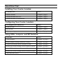
Read this First
Installing Your Courier I-modem
To install your
Go to
Internal modem
Chapter 4, page 1
External modem into a PC
Chapter 5, page 1
External modem to a Macintosh
Chapter 5, page 1
Configuring Your Courier I-modem
To configure your Courier for
Go to
Windows 95®
Chapter 8, page 1
Macintosh®
Chapter 9, page 1
Other operating systems
Chapter 10, page 1
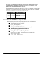
Using LEDs, Jumpers, and DIP Switches
To do this
Go to
Locate jumpers
Chapter 12, page 5
Modify jumper settings (internal Courier)
Chapter 12, page 5
Locate DIP switches on the internal Courier
Chapter 12, page 3
Modify DIP switch settings on the internal Courier
Chapter 12, page 3
Locate DIP switches on the external Courier
Chapter 12, page 1
Modify DIP switch settings on the external Courier
Chapter 12, page 1
Understand the LEDs
Chapter 13, page 1
Contents
Chapter 1 Introduction.............................................................................................1-1
How to Use this Guide ...............................................................................................1-1
Contacting U.S. Robotics...........................................................................................1-1
I-modem Features......................................................................................................1-2
Dial Security to Control Access to Your System .....................................................1-2
Testing...................................................................................................................1-2
Flash ROM Upgradability .....................................................................................1-2
Plug and Play Support for Windows 95..................................................................1-2
Remote Configuration and Diagnostics..................................................................1-2
Terminal Adapter Features....................................................................................1-3
Integral V.Everything Modem Features .................................................................1-4
Chapter 2 The I-modem and ISDN ..........................................................................2-1
Overview....................................................................................................................2-1
Internal I-modem....................................................................................................2-1
External I-modem ...................................................................................................2-1
External I-modem for Macintosh ............................................................................2-1
What is ISDN? ...........................................................................................................2-2
Benefits of ISDN.....................................................................................................2-2
The ISDN Basic Rate Interface ...............................................................................2-2
How Does the I-modem Fit In? ...................................................................................2-4
U-Interface with Integrated NT-1............................................................................2-5
S/T Interface...........................................................................................................2-5
Setting Up Your I-modem for ISDN ...........................................................................2-6
How the I-modem Calls a Variety of Devices..............................................................2-6
Internet Access (TurboPPP)....................................................................................2-6
Universal Connect..................................................................................................2-7
V.110 Connections..................................................................................................2-7
Modem and Fax Calls.............................................................................................2-7
Clear-Channel Synchronous Connections...............................................................2-7
Chapter 3 Ordering ISDN Service...........................................................................3-1
Overview...................................................................................................................3-1
The U.S. Robotics I-team .......................................................................................3-1
Requesting ISDN Service ..........................................................................................3-2
Chapter 4 Installing Your Internal I-modem .........................................................4-1
Requirements .............................................................................................................4-1
Configuration Manager Requirements ........................................................................4-1
Package Contents .......................................................................................................4-2
Important! ..................................................................................................................4-3
Installing Your Internal I-modem ...............................................................................4-4
Step One: Configuring with Jumpers ......................................................................4-4
Step Two : Configuring with DIP Switches..............................................................4-6
Step Three: Inserting the Modem ............................................................................4-8
Step Four: Connecting the Cables ........................................................................4-10
Testing the Installation .............................................................................................4-11
Chapter 5 Installing Your External I-modem.........................................................5-1
What You Need..........................................................................................................5-1
Package Contents .......................................................................................................5-1
Installing Your External I-modem ..............................................................................5-2
Step One: Connecting the Serial Cable...................................................................5-3
Step Two: Connecting the ISDN Cable ...................................................................5-4
Chapter 6 Using the Configuration Manager ..........................................................6-1
Overview....................................................................................................................6-1
Configuration Manager ..........................................................................................6-1
Configuring the I-modem........................................................................................6-1
What You Should Know.............................................................................................6-1
Directory Numbers .................................................................................................6-1
Service Profile Identifiers .......................................................................................6-2
Terminal Endpoint Identifier ..................................................................................6-2
Installing the Configuration Manager .........................................................................6-2
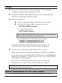
Configuring the I-modem ...........................................................................................6-3
Testing .......................................................................................................................6-8
Special Considerations for AT&T 5ESS Custom ........................................................6-8
If You Have No SPIDS and Only One DN ...............................................................6-9
If You Have One SPID and One DN......................................................................6-10
Chapter 7 Configuring With AT Commands...........................................................7-1
Overview....................................................................................................................7-1
Configuring the I-modem........................................................................................7-1
What You Should Know.............................................................................................7-1
Directory Numbers .................................................................................................7-1
Service Profile Identifiers .......................................................................................7-1
Terminal Endpoint Identifier ..................................................................................7-1
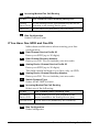
Preparing to Send AT Commands ..............................................................................7-2
Configuring and Testing Your I-modem.....................................................................7-3
Step One: Configuring the I-modem........................................................................7-3
Step Two: Checking the Configuration....................................................................7-6
Step Three: Saving the Configuration .....................................................................7-6
Step Four: Testing the Configuration......................................................................7-7
Special Considerations for AT&T 5ESS Custom ........................................................7-8
If You Have No SPIDs and Only One DN................................................................7-9
If You Have One SPID and One DN......................................................................7-10
Chapter 8 Configuring Your Courier For Windows 95..........................................8-1
Overview....................................................................................................................8-1
What You Need..........................................................................................................8-1
Configuring Your Courier With Plug and Play ...........................................................8-1
Files Needed By Your I-modem..................................................................................8-3
Installing the Latest I-modem Software ......................................................................8-4
Accessing Your Internet Service Provider...................................................................8-4
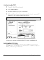
Step One: Determine if Dial-Up Networking is Installed.........................................8-4
Step Two: Installing Dial-Up TCP/IP Support ........................................................8-7
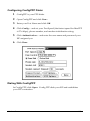
Step Three: Setting Up a Connection to Your ISP ...................................................8-8
Step Four: Customizing the TCP/IP Settings.........................................................8-11
Chapter 9 Configuring Your I-modem For Macintosh...........................................9-1
Handshaking Cable ....................................................................................................9-1
System Configuration .................................................................................................9-1
Accessing the Internet ................................................................................................9-1
Configuring MacTCP .............................................................................................9-2
Installing MacPPP Dialer ......................................................................................9-2
Configuring ConfigPPP Dialer...............................................................................9-3
Dialing With ConfigPPP.........................................................................................9-3
Chapter 10 Configuring Your I-modem for Other Operating Systems ...............10-1
If You Are Using Windows 3.x................................................................................10-1
If You Are Using Windows NT 4.0..........................................................................10-2
What You Need ....................................................................................................10-2
Configuring Your I-modem ..................................................................................10-2
Installing the Latest I-modem Software ................................................................10-2
If You Are Using MS-DOS......................................................................................10-3
If You Are Using OS/2 ............................................................................................10-4
If You Are Using UNIX, Linux, or AIX ..................................................................10-5
Chapter 11 Configuring TurboPPP With AT Commands.....................................11-1
Overview.................................................................................................................11-1
Point to Point Protocol (PPP) / ML-PPP...................................................................11-1
Determining TurboPPP Settings ..........................................................................11-1
Setting PPP/ML-PPP Host and Originate Mode ..................................................11-2
Making Calls With ML-PPP ................................................................................11-2
Dynamic Data Bandwidth Allocation.......................................................................11-4
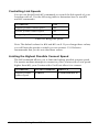
Controlling Dynamic Bandwidth Allocation in ML-PPP ......................................11-4
Setting When the Second Link Comes Up.............................................................11-5
Setting When the Second Link Comes Down.........................................................11-5
Enabling the Tone When the Second Link Comes Up ...........................................11-5
Using Compression in TurboPPP mode ...............................................................11-6
Chapter 12 Configuring Your I-modem With DIP Switches and Jumpers...........12-1
DIP Switches on the External I-modem ....................................................................12-1
Locating DIP Switches..........................................................................................12-1
Default DIP Switches (Model U)...........................................................................12-1
Default DIP Switches (Model U, V.35)..................................................................12-2
Default DIP Switches (Model S/T) ........................................................................12-2
DIP Switches on the Internal I-modem .....................................................................12-3
Locating DIP Switches..........................................................................................12-3
Default DIP Switches............................................................................................12-3
Using DIP Switches to Configure Your I-modem...................................................12-4
Jumpers on the Internal I-modem .............................................................................12-4
Locating Jumpers .................................................................................................12-4
Changing Jumper Settings ....................................................................................12-5
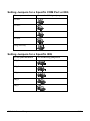
Setting Jumpers for a Specific COM Port .............................................................12-6
Setting Jumpers for a Specific IRQ .......................................................................12-6
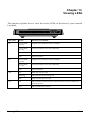
Chapter 13 Viewing LEDs......................................................................................13-1
Chapter 14 Using x2 ...............................................................................................14-1
Enhanced x2 Features..............................................................................................14-1
How to Tell if x2 is Enabled in Your I-modem ........................................................14-2
Obtaining x2 ...........................................................................................................14-2
How x2 Works.........................................................................................................14-3
Controlling x2 .........................................................................................................14-3
x2 Server Mode ...................................................................................................14-3
x2 Symmetric Mode (Host Mode) .........................................................................14-3
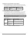
Controlling Link Speeds with &N and &U ..............................................................14-3
Controlling Link Speeds ......................................................................................14-4
Limiting the Highest Possible Connect Speed ......................................................14-4
Limiting the Lowest Possible Connect Speed........................................................14-5
Limiting a Range of Possible Connect Speeds......................................................14-5
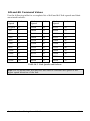
&N and &U Command Values .............................................................................14-6
Troubleshooting x2 Client Connections ...................................................................14-7
New x2 Result Codes...............................................................................................14-8
Appendix A Other I-modem Features..................................................................... A-1
Data Over Voice....................................................................................................... A-1
Protocols Supported by Data Over Voice.............................................................. A-1
Configuring Data Over Voice ............................................................................... A-1
Period Dial Modifier................................................................................................. A-2
PCSDL vs. XMODEM ............................................................................................. A-2
230 kbps DTE Rate Under Windows®...................................................................... A-2
Saving Money With Analog Calls............................................................................. A-3
Appendix B Technical Information......................................................................... B-1
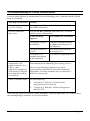
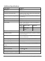
Technical Specifications ........................................................................................... B-1
Standards Compatibility ....................................................................................... B-1
ISDN .................................................................................................................... B-1
Modulation........................................................................................................... B-2
Error Control, Data Compression, Testing, and Dialing....................................... B-3
Fax....................................................................................................................... B-3
Additional Specifications...................................................................................... B-4
Ringer Equivalence .............................................................................................. B-5
Power Consumption ................................................................................................. B-5
Serial Ports............................................................................................................... B-5
The EIA-232 Interface.............................................................................................. B-6
Wiring a DB-25 to DB-9 Cable............................................................................. B-7
Minimum Requirements ........................................................................................ B-7
For Macintosh Computers ........................................................................................ B-8
Serial Ports (Macintosh modem)........................................................................... B-9
Appendix C The Serial Port .................................................................................... C-1
Choosing a Serial Cable ............................................................................................ C-1
Macintosh ................................................................................................................. C-2
Appendix D Warranty............................................................................................. D-1
U.S. Robotics Access Corp. Limited Warranty........................................................... D-1
Terms of the Limited Warranty .............................................................................. D-1
What Is NOT Covered By the Limited Warranty ....................................................... D-3
How To Access Your Warranty Services.................................................................... D-4
Notices ...................................................................................................................... D-7
FCC Registration .................................................................................................. D-7
IC (Industry Canada)............................................................................................. D-8
UL Listed Accessory .............................................................................................. D-9
Chapter 1
Introduction
How to Use this Guide
Use this Getting Started Guide to obtain the information you need to get your
Courier™ I-modem® modem installed, configured, and running correctly.
For more information about advanced commands, view the I-modem
Command Reference, which is on the Connections CD-ROM.
If you understand how ISDN works, you can skip directly to Chapter 3,
Ordering ISDN.
Contacting U.S. Robotics
Please contact U.S. Robotics if you have any questions.
To do this
Contact
Contact U.S. Robotics Technical Support
1.800.231.8770
Use the Fax-on-Demand service
1.800.762.6163
Download updated I-modem x2 code from
the U.S. Robotics Bulletin Board System
847.982.5092 (analog)
Download updated I-modem code
http://totalservice.usr.com
Visit the U.S. Robotics web site
http://www.usr.com
Visit U.S. Robotics on Compuserve
GO USROBOTICS
Visit U.S. Robotics on America Online
Keyword: USROBOTICS
Introduction
847.734.8612 (V.120 ISDN)
1-1
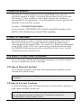
I-modem Features
Dial Security to Control Access to Your System
The Courier’s Dial Security feature allows you to control access at a
modem-to-modem level instead of using software that runs on the host
computer. With Dial Security, you can prevent unauthorized access to a
system through the use of password prompting and dial-back.
Testing
ITU-T V.54 loopback testing is available. The Courier can perform analog,
digital, and remote digital loopback tests to determine if there are
problems with the phone line, the remote device, or your Courier’s
transmitter or receiver.
Flash ROM Upgradability
Courier modems are software-upgradable using XMODEM file transfers
and U.S. Robotics Software Download (SDL) application, allowing you
quick, easy access to updates of your Courier’s technology. The latest
upgrades can be obtained on the U.S. Robotics web site or Bulletin Board
System.
Plug and Play Support for Windows 95
The software for the external and internal Courier has been developed to
support Plug and Play (as defined by the Plug and Play External and
Internal COM Device Specification, Version 1.00). When you connect your
Courier to a computer that uses a Plug and Play operating system, the
computer automatically detects and configure itself to the support your
Courier.
Remote Configuration and Diagnostics
You can remotely configure and test your Courier. If you are a network
administrator supporting remote users, this feature can save you time and
money.
Terminal Adapter Features
ISDN Terminal Adapter
The I-modem is an ISDN terminal adapter; it enables your computer to
1-2
Courier I-modem Getting Started Guide
communicate on the ISDN at speeds of up to 64 kbps.
Optional Built-in NT-1
The I-modems with Integrated NT-1 contain an on-board NT-1, sparing you
the expense and extra cabling associated with an external NT-1.
Optional Analog Device Jack
The I-modem with Integrated NT-1 and Analog Device Jack allows you to plug
in an analog telephone, fax machine, or modem, allowing analog devices
to communicate over an ISDN B-channel. This applies to external units
only.
TurboPPP
TurboPPP is U.S. Robotics’ unique combination of asynchronousto-synchronous PPP conversion, compression, multilink PPP (ML-PPP).
You can use TurboPPP to access the Internet or remote local-area
networks (LANs) at speeds of up to 128 kbps before compression and up
to 512 kbps with compression.
Rate Adaptation
The I-modem’s support of the V.120 and V.110 protocols allows it to map
slower-speed asynchronous data to the 64-kbps B-channel. The
I-modem’s rate adaptation capability spans the range of 300 to 57600 bps.
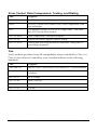
Central Office Switch Compatibility
Works with AT&T 5ESS and Northern Telecom DMS-100 switches that
run either their custom protocols or National ISDN-1, as well as with
other manufacturer’s switches that use National ISDN-1 or National
ISDN-2 call control signaling (ITU-T Q.931/I.451 call control signaling).
Introduction
1-3
Link Diagnostics
After each call, you can display a Link Diagnostics screen (ATI6) containing information about the last call, including the number of data
characters transferred, line statistics, the call's rate, and the reason the call
was disconnected.
Switched-56 Support
The I-modem can communicate to remote devices connected via
Switched-56 circuits.
V.120 and V.110 Connections
V.120 and V.110 are standards for passing asynchronous data over ISDN
B-channels, which are inherently synchronous. To make a connection
using V.120 or V.110, devices at both ends of the connection must support
V.120 or V.110.
Modem and Fax Calls
The I-modem emulates an analog fax/modem, allowing you to connect to
remote analog modems and fax machines using 3.1 kHz audio format.
Voice Calls
If your I-modem has an Analog Device port, you can connect a standard,
analog telephone and use the phone over your ISDN line. Be aware that
the internal I-modem cannot provide ringing voltage through the Analog
Device port, so equipment that autoanswers, such as a fax or answering
machine, will not work correctly.
Integral V.Everything Modem Features
Supports Analog Fax/Modem Calls
The I-modem always makes and receives calls over ISDN. Since there is
no guarantee that the device at the other end of the line is ISDN-capable,
the I-modem can communicate with non-ISDN devices, such as analog
modems and Group III fax.
1-4
Courier I-modem Getting Started Guide
x2 56-kbps Connectivity
If you have enabled x2, your Courier can connect at speeds up to
56 kbps. While line conditions may not always allow for 56 kbps
connections, the new Courier software allows you to achieve the fastest
analog speeds available.
Adaptive Speed Leveling to Adjust to Line Conditions
Adaptive Speed Leveling® (ASL) allows your Courier to monitor line
conditions while connected, and fall back to the next lower speed if
conditions are poor. Couriers also detect improved line conditions and
shift upward to the next higher speed. The transmit and receive channels
adapt independently, each detecting and adjusting to line conditions.
Calls to and from Modems and Fax Machines
When used with fax-capable communications software, your Courier
auto-detects and responds to calls from modems and Group III fax
machines using EIA-standard Class 1 or 2.0 fax software.
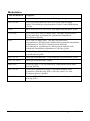
Data Compression
V.42 bis/MNP5
Data compression enables throughput of up to 230.4 kbps on analog
connections. I-modems connecting under V.42 or HST error control use
V.42bis compression. I-modems connecting under MNP error control use
MNP Level 5 compression. Typically, files can be compressed from 2:1 to
4:1.
Error Control
V.42/MNP
Data integrity is ensured when the I-modem connects with remote devices
that use the V.42 (LAPM), HST, or MNP error control protocols. Error
control is available on analog calls at 1200 bps and above.
V.Everything
The Courier provides full support of the x2, V.34 standard, V.Fast Class,
V.32 terbo, and many other modulation schemes, spanning the range of
speeds between 300 bps and 56 kbps.
Introduction
1-5
1-6
Courier I-modem Getting Started Guide
Chapter 2
The I-modem and ISDN
The Courier I-modem with ISDN/V.Everything is an Integrated Services
Digital Network (ISDN) terminal adapter that can perform all the
functions of a Courier V.Everything fax/modem.
Overview
The I-modem is capable of exchanging data over the ISDN at speeds of up
to 128 kbps with ISDN devices or up to 56 kbps with analog devices,
before compression.
Internal I-modem
There are two versions of the internal I-modem:
•
•
The ISDN U-Interface with an analog device jack (Model U)
The ISDN S/T-Interface (Model S/T)
External I-modem
There are two versions of the external I-modem:
•
•
The ISDN U-Interface with an analog device jack (Model U)
The ISDN S/T-Interface (Model S/T)
External I-modem for Macintosh
There is one version of the I-modem for Macintosh. The Courier I-modem
for Macintosh is the same as Model U (ISDN U-Interface with Analog
Device Jack).
The I-modem and ISDN
2-1
What is ISDN?
Integrated Services Digital Network is an application of digital technology
that provides end-to-end digital service over the public communications
network. ISDN was designed to integrate the transmissions from a
variety of devices, (computers, telephones, and fax machines) into one
digital network.
Because ISDN was designed for transmitting digital information, it has
many advantages over the analog telephone network. Digital
transmission is more accurate and reliable, and that helps increase
transmission speeds to up to 64 kbps per channel.
Benefits of ISDN
The benefits of ISDN include:
•
•
•
Increased bandwidth
Fewer errors during data transfer
Quicker call setups and teardowns.
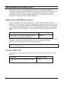
The ISDN Basic Rate Interface
Physical Appearance
The I-modem communicates over an ISDN Basic Rate Interface (BRI) line.
You must order a BRI line from your local telephone company before you
can use your I-modem. Chapter 2, Ordering ISDN Service, explains how to
order ISDN and which services to request.
BRI works over the same wiring that is in place for your analog telephone
lines. The difference is in the equipment you attach and the signaling
used.
RJ45 Connector
RJ45 Jack
RJ11 Connector
RJ11 Jack
Figure 2.4 RJ45 and RJ11 Connectors and Jacks.
2-2
Courier I-modem Getting Started Guide
At your site, the BRI line takes the form of an RJ45 or RJ11 wall jack,
which in ISDN is called the U interface. RJ45 connectors have eight pins
and RJ11s have four or six pins. At the U-interface, you can plug an RJ11
connector into an RJ45 jack, and your line will work correctly.
The telephone company adds a line termination device at their end of the
BRI that adapts the line for ISDN.
B-channels and D-channels
Though BRI signals are transmitted over an ordinary pair of wires, BRI
typically contains three channels. The channels are created by complex
signaling techniques.
BRI is composed of two 64-kbps B-channels and one 16-kbps D-channel:
This
Does this
B-channels
Carries (or “Bears”) data or voice traffic
D-channel
Sets up and tears down calls
Logical View
D-channel (16 Kbps)
B-channel (64 Kbps)
B-channel (64 Kbps)
Physical View
RJ45 Connector
Figure 2.5 ISDN BRI—Three Logical Channels Over One Pair of
Wires.
The I-modem and ISDN
2-3
Required Components
BRI-line signals must be translated into signals your computer can
understand. Several devices must be in place to perform the translation.
This
Is a device
TE2
That does not have built-in ISDN capability.
TE2s require Terminal Adapters (TAs),
such as the I-modem, to communicate over
the ISDN. Example: Computer.
(Terminal Equipment 2)
TA
(Terminal Adapter)
NT-1
(Network Termination
[Unit] -1
That translates between non-ISDN signaling
that TE2s provide (such as EIA-232) and the
S/T-interface signaling that the NT-1
understands.
That ranslates between the short-distance
signaling used at the S/T-interface and the
longer-distance signaling used at the
U-interface. NT-1s also convert from the
two wires used for the phone line to the six
or eight wires needed for the S/T bus.
How Does the I-modem Fit In?
The I-modem needs an NT-1 device to work with ISDN. If you currently
use an NT-1 device, you can use the S/T-interface I-modem.
2-4
This version of I-modem
Allows the I-modem to connect
U-Interface Integrated NT-1
Directly to the U-interface
S/T-Interface
To an external NT-1 device (you must
have an NT-1 device)
Courier I-modem Getting Started Guide
U-Interface with Integrated NT-1
Figure 1–5 illustrates how the I-modems with Integrated NT-1 connect
your computer to the ISDN.
BRI Line
I-modem
ISDN
U
Figure 2.6 A Typical Installation of the I-modem
Once you’ve subscribed to ISDN service (see Chapter 2, Ordering ISDN
Service, for much more detail), your local telephone company will install a
BRI line at your site.
You install the I-modem in your computer and connect a cable between
the I-modem and the phone jack. Then run the I-modem Configuration
Manager or send commands to change a few settings. Before long, you’ll
be making calls on the ISDN.
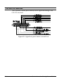
S/T Interface
Figure 2.6 illustrates how the I-modem S/T connects your computer to the
ISDN.
Note: Some NT-1s contain an integrated power supply.
Power
NT-1 Supply AC Power
BRI
ISDN
U
U + Power
S/T
I-modem
Figure 2.7 A Typical Installation of the I-modem S/T.
The I-modem and ISDN
2-5
Setting Up Your I-modem for ISDN
You can get your ISDN service working by following these five easy steps:
Step One: Subscribe to ISDN service.
Step Two: Your local telephone company will install a BRI line at your
site.
Step Three: Install the I-modem in your computer.
Step Four: Purchase and install an NT-1 (if necessary) and connect the
cables.
Step Five: Run the I-modem Configuration Manager and change a few
settings.
How the I-modem Calls a Variety of Devices
When you use the I-modem, all your calls go over one or both ISDN
B-channels. However, you can set the I-modem to make different kinds of
calls over the B-channel:
Internet Access (TurboPPP)
TurboPPP makes the most of your ISDN line in a way that’s transparent
to your computer and the networking applications running on it. You can
use TurboPPP to access the Internet or remote local-area networks (LANs)
at speeds of up to 128 Kbps before compression and up to 512 Kbps with
compression.
TurboPPP is U.S. Robotics’ unique combination of
asynchronous-to-synchronous PPP conversion, compression, multilink
PPP (MP-PPP), and PPP/MP-PPP spoofing.
Asynchronous-to-Synchronous PPP Conversion
Most Internet service providers that allow ISDN connections expect your
data to arrive in synchronous Point-to-Point Protocol (PPP) format. Most
computers, however, can’t deliver synchronous PPP through their serial
ports.
To solve this problem, the I-modem has the ability to convert
asynchronous PPP data to synchronous PPP. This capability allows you
to use networking software that is intended for asynchronous PPP
connections (such as Windows 95 Dial-Up Networking or NetManage
Chameleon) to access the Internet or remote LANs.
2-6
Courier I-modem Getting Started Guide
Compression
The I-modem supports the leading de-facto standards for compression
over ISDN: Stac LZS, Microsoft, and Ascend.
Multilink PPP (MP-PPP)
Multilink PPP support enables the I-modem to use both of the available
B-channels simultaneously. The I-modem uses PPP/MP-PPP spoofing to
mediate between applications running on your computer, which may not
be aware of MP-PPP, and host computers that support MP-PPP. In effect,
the I-modem tricks both ends of the connection, keeping them happy
communicating the way they’re accustomed, while maximizing
throughput.
Universal Connect
When the I-modem is set to Universal Connect, it autosenses V.120, V.110,
or analog fax/modem connections. Use Universal Connect when calling
ISDN or analog Bulletin Board Systems (BBSs), for example. For details,
see Chapter 11, Handshaking, Error Control, Data Compression, and
Throughput, in the I-modem Command Reference manual.
V.110 Connections
V.120 and V.110 are standards for passing asynchronous data over ISDN
B-channels, which are inherently synchronous. To make a connection
using V.120 or V.110, the device at the other end of the connection must
also support V.120 or V.110. A typical application of V.120 is for BBSs.
Modem and Fax Calls
The I-modem emulates an analog fax/modem, allowing you to connect to
remote analog modems and fax machines.
Clear-Channel Synchronous Connections
When you set the I-modem to make clear-channel synchronous
connections, it sets up a 64 Kbps connection with a remote device,
enabling you to exchange any kind of synchronous data. Common
applications of clear-channel synchronous are videoconferencing and
remote access to mini- or mainframe computers.
The I-modem and ISDN
2-7
2-8
Courier I-modem Getting Started Guide
Chapter 3
Ordering ISDN Service
This chapter gives you and your local telephone company all the
information needed to set up the lines correctly.
Overview
To order ISDN service, contact your local telephone company, give them
information about your I-modem, and record information that they give
you, such as your new ISDN telephone numbers, called SPIDs.
If you decide that you would like assistance with the ordering process,
call the U. S. Robotics I-team at (888) USR-ISDN.
The U.S. Robotics I-team
The I-team is a subset of U.S. Robotics’ Customer Support department
that provides assistance with the ISDN ordering and configuring process.
The I-team determines the availability and pricing of ISDN service in your
area, installation costs, lead time for installation, and will coordinate the
configuration of the telephone company’s equipment so your I-modem
will work properly.
Ordering ISDN Service
3-1
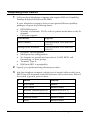
Requesting ISDN Service
1
Call your local telephone company and request Bellcore Capability
Package S (listed in Bellcore SR-3840).
If your telephone company does not recognize Bellcore capability
packages, request the following items:
•
•
ISDN BRI service.
Number of channels: 2B+D, with no packet-mode data on the Dchannel.
Call type support:
•
This channel
Supports
Data B-channel
Circuit-Switched Voice and Data
(CSV/D)
Analog Device B-channel
Circuit-Switched Voice and Data
(CSV/D)
•
•
•
Dynamic TEI assignment.
Multipoint bus configuration.
No features or special services such as CACH EKTS, call
forwarding, or hunt groups.
Terminal Type A.
RJ45 jack (RJ11 is acceptable).
•
•
3-2
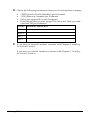
2
Specify your preferred long-distance provider.
3
Ask the telephone company which type of central-office switch your
ISDN line will terminate and which protocol the switch uses. Record
the switch type and protocol here:
ü
Switch
Protocol
r
AT&T 5ESS
Custom
r
AT&T 5ESS
National ISDN-1
r
Northern Telecom DMS-100
Custom (PVC 0 or 1)
r
Northern Telecom DMS-100
National ISDN-1 (PVC 2)
r
Siemens EWSD
National ISDN-1
r
Other
National ISDN-1
Courier I-modem Getting Started Guide
4
Obtain the following information from your local telephone company:
•
•
•
•
1 SPID (Service Profile Identifier) per B-channel.
1 DN (Directory Number) per B-channel.
Call types supported on each B-channel.
If the switch does not auto-assign TEIs (most do), then you need
one fixed TEI per B-channel.
For this
Record the number here
SPID 1
SPID 2
DN 1
DN 2
5
If you have an internal I-modem, continue with Chapter 4, Installing
the Internal I-modem.
If you have an external I-modem, continue with Chapter 5, Installing
the External I-modem.
Ordering ISDN Service
3-3
3-4
Courier I-modem Getting Started Guide
Chapter 4
Installing Your
Internal I-modem
This chapter explains how to:
•
•
•
•
Configure with jumpers
Configure with DIP switches
Insert the internal I-modem
Connect cables to the internal I-modem
Important: Review Chapter 2, The I-modem and ISDN, and Chapter 3,
Ordering ISDN Service, before installing the I-modem.
Requirements
You need the following to install your I-modem:
•
•
•
•
IBM-compatible computer with a free interface card slot
An ISDN Basic Rate Interface line
Communications software
An NT-1 and Power Supply (I-modem S/T only)
Note: An NT-1 is a device that terminates the ISDN line and translates
between the U-interface signaling from the telephone company and the
S/T-interface signaling needed by ISDN terminal devices, such as the
I-modem S/T. Only I-modem S/T’s require an external NT-1.
Configuration Manager Requirements
You need the following to run the U.S. Robotics I-modem Configuration
Manager software:
•
•
•
386SX, or better, CPU.
8 MB, or more, RAM.
DOS 5.0 or higher and Windows 3.1, or higher.
Installing the Internal I-modem
4-1
Package Contents
Your I-modem package contains the following items:
•
•
•
•
•
•
•
4-2
The I-modem
Telephone cable
Quick Reference card
Customer Support card
This Getting Started manual
I-modem Configuration Manager diskette.
The Connections CD-ROM, which contains:
– I-modem Command Reference Guide
– RapidComm communications software and manuals
– Stampede Remote Office Gold software and manuals
– Special offers
– Updated I-modem INF file
Courier I-modem Getting Started Guide
Important!
The I-modem emulates a serial interface card with a 16550 UART. Like
serial interface cards, it must be assigned a unique communications
(COM) port number and a unique interrupt request (IRQ) number.
If you are using a computer with a Plug and Play compliant BIOS and
operating system and you set the I-modem’s jumpers to Plug and Play
(the default), your computer’s operating system will take care of the COM
and IRQ settings for you.
Setting the COM port and IRQ yourself requires a detailed knowledge of
the settings of the other adapter cards in your computer. If other adapter
cards are set to use the same COM port or IRQ, conflicts may occur that
could result in data loss or lockups.
First, determine whether your computer has a Plug and Play ISA bus.
Check your computer’s documentation to be sure. Keep these points
about Plug and Play in mind:
•
•
Your computer’s operating system must support Plug and Play
(examples of those that do: OS/2 Warp, Windows 95, Windows NT),
or your computer’s manufacturer must supply you with Plug and
Play software.
Your computer’s Basic Input/Output System (BIOS) must support
Plug and Play.
Installing the Internal I-modem
4-3
Installing Your Internal I-modem
To install your internal I-modem, do the following:
Step One: Configure your I-modem with jumpers (if necessary)
Step Two: Configure your I-modem with DIPs (if necessary)
Step Three: Insert your I-modem
Step Four: Connect the cables
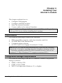
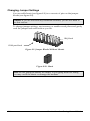
Step One: Configuring with Jumpers
Your I-modem comes configured for Plug and Play, which allows
Windows 95 to automatically configure itself to work with the
I-modem.
Jumpers
Figure 4.1 Jumpers
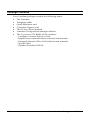
Default Jumper Settings
4-4
Courier I-modem Getting Started Guide
Figure 4.2 Default Jumper Settings
In addition to the shunt shown in Figure 4.2, the I-modem is shipped with
two additional shunts. These shunts do not affect the configuration of
your I-modem because they are attached to only one post; change the
positions of these shunts only if you need to change hardware settings.
Notes:
•
The S/T version has an additional set of jumpers.
•
For most configurations, default settings will work. However, if your
environment has multiple ISDN devices or you are using an NT-1, see
the I-modem Command Reference manual.
Windows 95 Users
If you are using Window 95, you should not need to change the Plug and
Play jumper settings, because Windows 95 automatically detects and
configures your Courier.
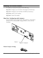
Other IBM-PC Compatible Operating Systems
If you are using an IBM-PC compatible operating system, you may need
to change the jumper settings to a COM port or IRQ setting that is not
already used by your system.
For information about setting jumpers for different COM ports and IRQ
settings, see Chapter 12, Configuring Your Courier With DIP Switches and
Jumpers.
Installing the Internal I-modem
4-5
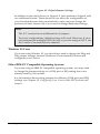
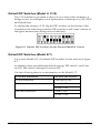
Step Two : Configuring with DIP Switches
You will probably not need to change the DIP switch settings, but review
this section to be sure.
The DIP (Dual Inline Package) switches are located on the bracket of the
I-modem. See Figure 3-7 to learn how to set the switches.
DIP switches
Figure 4.3 Location of the DIP Switches.
4-6
Courier I-modem Getting Started Guide
OFF ON
No effect
No effect
No effect
No effect
Ignore AT commands
Act on AT commands
Load &F0 template
settings on power-on or
reset
Load NVRAM settings
at power-on or reset
Figure 4.4 How to Set the DIP Switches.
For information about AT commands, refer to Chapter 2, Using the AT
Command Set, in the I-modem Command Reference manual.
This DIP
Switch
Position
Does this
ON (Default)
Loads the configuration that is stored
in non-volatile memory (NVRAM)
OFF
Loads the &F0 configuration that is
stored in read-only memory (ROM)
ON (Default)
Acts on AT commands (smart mode)
OFF
Ignores AT commands (dumb mode)
3
OFF
No effect
4
OFF
No effect
1
2
When you power on your computer or reset the I-modem, the DIP switch
settings override the settings you may have made previously using AT
commands.
Note: The following AT commands are not changed by a power-on or
reset and must be changed manually: &Cn, &Dn, En, Qn, Vn, S0=n,
S14=n, and S67=n.
If you change the DIP switch settings while the I-modem is on, you can
avoid powering your computer off to make the new settings take effect.
Just send the I-modem the ATZ or the ATZ! command. (ATZ! is a “hard”
reset, which is just like powering the I-modem off and then on. ATZ is a
“soft” reset, which is like rebooting the I-modem and not removing
power.)
Installing the Internal I-modem
4-7
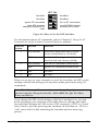
Step Three: Inserting the Modem
Note: The illustrations in this section may not match the appearance of
your computer. For more detail, refer to your computer’s user’s manual.
4-8
1
Turn off the computer’s power and unplug the computer’s power
cord. Ground yourself.
2
Remove the screws that hold on the computer’s cover and slide the
cover off.
3
Find an empty expansion slot that provides enough room to install
your Courier.
4
Remove the screw that holds on the slot cover and remove the slot
cover. Save the screw!
Courier I-modem Getting Started Guide
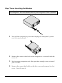
5
Insert your Courier into the slot and press down on the top edge of
your Courier until it is seated firmly.
6
Using the screw you saved in Step 4, secure your Courier in your
computer.
7
Replace the cover of your computer and tighten the screws.
You are now ready to connect the cables.
Installing the Internal I-modem
4-9
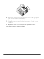
Step Four: Connecting the Cables
I-modems with Integrated NT-1 Model U
1
Connect one end of the U-interface cable to the ISDN BRI jack and the
other end to the I-modem.
2
If your I-modem has an Analog Device port, connect an analog
device, such as a standard telephone, now.
Be aware that the internal I-modem does not provide ringing voltage,
which may prevent normal operation of devices that auto answer
(such as fax or answering machines).
I-modem Model S/T
1
Connect one end of the S/T-interface cable to an S/T port on your
NT-1 and the other end to the I-modem.
NT-1
2
4-10
Install the NT-1 according to the steps listed in its documentation.
Courier I-modem Getting Started Guide
Testing the Installation
To test your Courier, use any communications software package, such as
Windows Terminal, HyperTerminal, Procomm Plus, or RapidComm.
HyperTerminal is used as an example. Every communications program is
different; consult the documentation that came with your communications
program for more information.
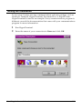
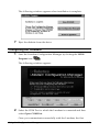
1
Run HyperTerminal.
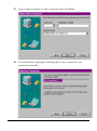
2
Enter the name of your connection in Name and click OK.
Installing the Internal I-modem
4-11
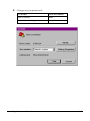
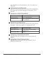
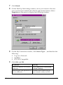
3
4-12
Enter the phone number you want to dial in Phone number and click
OK. If you only want to test your modem, you may enter any
number.
Courier I-modem Getting Started Guide
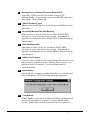
4
Change any properties and:
To do this
Click this button
Dial a number
Dial
Test without dialing a number
Cancel
Installing the Internal I-modem
4-13
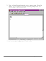
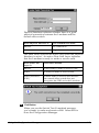
5
When the HyperTerminal terminal window appears, enter AT and hit
<enter>. If your modem is connected and configured properly, you
will see “OK” on the terminal screen.
You are now ready to configure your Courier modem.
4-14
Courier I-modem Getting Started Guide
Installing the Internal I-modem
4-15
Chapter 5
Installing Your
External I-modem
This chapter explains how to:
•
•
•
Connect the serial cable
Connect the ISDN cable
Connect the power cord
What You Need
You need the following to install your Courier I-modem:
•
•
Computer or terminal with a serial port (16650 UART recommended)
ISDN Basic Rate Interface (BRI) line
Package Contents
Your Courier I-modem package contains the following items:
•
•
•
•
•
•
•
Courier I-modem
Power adapter
Telephone cable
Quick Reference card
Customer Support card
This Getting Started manual
The Connections CD-ROM, which contains:
– Courier I-modem Command Reference Guide
– RapidComm communications software and manuals
– Stampede Remote Office Gold software and manuals
– Special offers
– An updated Courier I-modem INF file
Note about serial cables: You need a serial cable to connect your Courier
to your computer. Because there are a variety of connector types that
different computers require, and many users may already have an
existing modem and serial cable, a serial cable is not provided with your
Courier.
Installing the External Courier
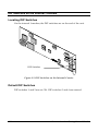
5-1
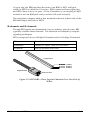
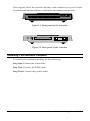
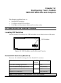
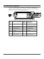
These figures show the controls, displays, and connectors on your Courier
I-modem and indicate where to find more information about each.
B1
B2
AA
CD
NS
RD
SD
DTR
MR
RTS
CTS
SYNC ARQ/
FAX
with ISDN/V.34
Figure 5.1 Front panel of the I-modem
ON/OFF
POWER
DATA
PHONE
U
I/ O
Figure 5.2 Rear panel of the I-modem
Installing Your External I-modem
To install your external I-modem, do the following:
Step One: Connect the serial cable
Step Two: Connect the ISDN cable
Step Three: Connect the power cable
5-2
Courier I-modem Getting Started Guide
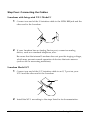
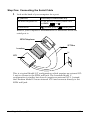
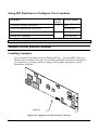
Step One: Connecting the Serial Cable
1
Look at the back of your computer for a port:
If you have
Ports may be labeled this way
An IBM-compatible PC
COM, RS-232, or with symbols such
as IOIOI,
, or .
A Macintosh
(modem port) or
(printer port)
Refer to your computer’s documentation to determine where the
serial port is.
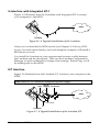
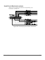
ISDN Telephone
S/T Bus
I-modem
U
NT-1
This is a typical Model S/T configuration, which requires an external NT1 unit to connect to the ISDN wall jack. The I-modem Model U
configuration is similar, but does not require an external NT-1. Instead,
the I-modem Model U has an internal NT-1 and connects directly to the
ISDN wall jack.
Installing the External Courier
5-3
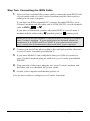
Step Two: Connecting the ISDN Cable
1
After you have selected the correct cable, connect the male DB-25 end
of your serial cable to your Courier I-modem and the other end to a
serial port on your computer.
If you have an IBM-compatible PC, connect the male DB-25 to your
Courier I-modem and the other end to COM, RS-232, or with symbols
, or .
such as IOIOI,
If you have a Macintosh, connect the male DB-25 to your Courier Imodem and the other end to
(modem port) or
(printer port)
Note: Write down the number of the serial port to which you connect
your Courier I-modem. If your serial ports are lettered instead of
numbered, A is COM1 and B is COM2. If you cannot find a serial
port, consult the documentation that came with your computer.
2
Connect one end of the phone cable to the wall jack and the other end
to your Courier I-modem port labeled U.
3
If you have Model U and a telephone that you’d like to connect to
your Courier I-modem, plug its cable into your Courier port labeled
PHONE.
4
Plug one end of the power adapter into your Courier I-modem and
the other end to a standard AC power outlet.
5
Switch your computer and modem power on.
You are now ready to configure your Courier I-modem.
5-4
Courier I-modem Getting Started Guide
Chapter 6
Using the Configuration Manager
This chapter explains how to configure and test the I-modem using the
Configuration Manager software.
If the computer to which you’ve connected the I-modem cannot run
Windows applications, follow the steps in Chapter 7, Configuring With AT
Commands.
Overview
Configuration Manager
The I-modem Configuration Manager is designed to help you make the
ISDN settings to your I-modem and test whether you have a working
connection with the central-office switch.
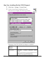
Configuring the I-modem
Before you can make any calls, you need to configure the I-modem to
work on your ISDN line. If you haven’t ordered an ISDN line, see
Chapter 3, Ordering ISDN Service.
Install and run the Windows Configuration Manager software shipped
with the I-modem. The Configuration Manager runs on Windows 3.1,
Windows 95, Windows NT, and Macintosh.
What You Should Know
Directory Numbers
Directory Numbers (DNs) take the form of ordinary seven- or ten-digit
telephone numbers. Be sure to leave off the area code from your DN.
Using the Configuration Manager
6-1
Service Profile Identifiers
Service Profile Identifiers (SPIDs) tell the telephone company about any
special services and features to which you've subscribed. SPIDs can be up
to 20 digits long.
Terminal Endpoint Identifier
The TEI is a one or two digit number that permanently identify a your
connection with the central office switch.
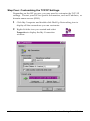
Installing the Configuration Manager
1
Make sure the I-modem is attached to your computer and powered
on.
2
Power-on your computer and start Windows.
3
Insert the Courier I-modem Configuration Manager diskette in drive
A (or drive B).
4
Windows 3.x: From the Program Manager group’s menu bar, select
File, and then Run...
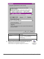
Windows 95: Click Start, and then Run…
5
Enter a:\setup (or b:\setup, depending on the drive into which you
inserted the diskette). The installation program will start.
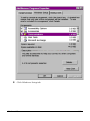
6
When you’re prompted, enter the drive and directory where you
want the Configuration Manager installed. The default is
c:\i-modem.
The installation program installs the software and creates an I-modem
Configuration Manager program group and icons.
6-2
Courier I-modem Getting Started Guide
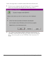
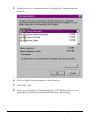
The following window appears when installation is complete.
7
Eject the diskette from the drive.
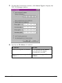
Configuring the I-modem
1
Start the I-modem Configuration Manager by clicking the ISDN
Program icon:
The following window appears:
2
Select the COM Port to which the I-modem is connected and then
select Open COM Port.
Once you communicate successfully with the I-modem, the first
Using the Configuration Manager
6-3
window disappears and the following window appears:
(If you cannot communicate with the I-modem, you may have a COM
port or IRQ conflict. Refer to Chapter 15, Troubleshooting, in the
I-modem Command Reference manual.)
1
10
2
11
3
4
5
12
6
7
13
8
9
14
1
15
16
Data Channel Call Type
Choose one of the following call types for the Data Bchannel. Your choice applies for both incoming and
outgoing calls.
2
This call type
Allows these types of calls
Automatic Service Choice
V.120, then analog fax/modem
V.120 Rate Adaptation
V.120 only
V.110 Rate Adaptation
V.110 only
Analog Modem
Analog fax/modem only
Clear Channel
Clear-channel synchronous
Internet Access
TurboPPP, then analog fax/modem
Data Channel Service Profile ID
Enter the SPID (up to 20 digits) for the Data B-channel.
3
6-4
Data Channel Directory Number
Courier I-modem Getting Started Guide
Enter the DN for the Data B-channel. Do not include your
area code.
4
Data Channel Terminal Endpoint ID
Typically, ISDN service providers assign TEIs automatically.
If you were given a fixed TEI, type it in this blank. If not,
leave 00.
5
6
Analog Device Channel Dialing Method
If you select
The I-modem dials
Standard Analog
Like a standard phone.
All Digits At Once
Like a cellular phone (press # to send
dialed number).
Analog Device Channel Call Type
Choose one of the following call types for the Analog Device
B-channel. Your choice applies to outgoing calls only.
7
If you want to use
Select this call type
Higher quality audio
3.1 kHz audio or speech (Analog
Modem or Fax)
Lower quality audio
Speech
Analog Device Channel Service Profile ID
Enter the SPID (up to 20 digits) for the Analog Device Bchannel.
8
Analog Device Channel Directory Number
Enter the DN for the Analog Device B-channel. Do not
include your area code.
Using the Configuration Manager
6-5
9
Analog Device Channel Terminal Endpoint ID
Typically, ISDN service providers assign TEIs
automatically. If you were given a fixed TEI, type it in
this blank. If not, leave 00.
10
Switch Protocol Type
Choose the switch protocol used by your ISDN service
provider.
11
Incoming Modem/Fax Call Routing
This section is active only if you select AT&T 5ESS
Custom as your switch protocol type. Explained in
Special Considerations for AT&T 5ESS Custom later in
this chapter.
12
Bus Configuration
This field is active only if you select AT&T 5ESS
Custom as your switch protocol type. Explained in
Special Considerations for AT&T 5ESS Custom later in
this chapter.
13
Audio Port Volume
Controls the volume of the sound from the receiver of a
device that’s attached to the Analog Device port. 0 is
quietest and 9 is loudest. 4 is the default and is
recommended.
14
Save Button
Check all the settings to make sure they’re correct, and
then click Save. The following message appears:
15
Test Button
Select Test to reset the I-modem and begin a 90-second
period of attempts to connect to your central office
switch. Watch the Switch Connectivity Test window.
6-6
Courier I-modem Getting Started Guide
Physical Interface indicates whether there is a good
physical connection between the I-modem and the
central-office switch.
If the Physical Interface is
The I-modem has made
Inactive
No connection.
Active
A good connection.
The Data Link Layer can be active only when the Physical
Interface is active. An active Data Link Layer indicates
that the I-modem is ready to make or receive calls.
16
If the Data Link
Layer is
Then the I-modem
Inactive
Is not ready to make or receive calls.
Active
Is ready to make or receive calls.
Active (Incorrect
SPID)
Cannot make or receive calls because
the central office switch does not
recognize the SPID set in the I-modem.
Exit Button
When you see the Switch Test Completed message,
you’re ready to make and receive calls! Select Exit to
close the Configuration Manager.
Using the Configuration Manager
6-7
Testing
1
Start your communications software package. Use a terminal
emulation program, such as HyperTerminal.
2
Change the COM port and IRQ settings in your communications
software to match the I-modem’s setup.
3
Make a test data call.
a
b
Put your communications software in Terminal Mode.
Call the U.S. Robotics BBS. Type the following:
ATDT18477348612 <Enter>
Or, in the 847 area code:
ATDT7348612 <Enter>
Note: When you make ISDN calls, you won’t hear dialing or
training tones when the call is being made.
You should see one of the following messages:
CONNECT 56000/ARQ/DIGITAL/V120
CONNECT 64000/ARQ/DIGITAL/V120
If you don’t see one of these messages, refer to Chapter 15,
Troubleshooting, in the I-modem Command Reference manual.
4
I-modems with Analog Device Jack: Make a test voice call.
When the network connects the call, the B1 or B2 LED should flash.
If you have set up your analog device B-channel to use All Digits At
Once (en-bloc) dialing, you must press the star (*) key after you dial
the number in order to send it.
If you have trouble making analog calls, refer to Chapter 15,
Troubleshooting, in the I-modem Command Reference manual.
Note: Any device attached to the Analog Device port cannot use the line
unless the I-modem is powered on.
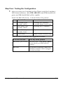
Special Considerations for AT&T 5ESS Custom
If your central-office switch is an AT&T 5ESS that runs the Custom
6-8
Courier I-modem Getting Started Guide
protocol, you can use fewer than two SPIDs/DNs, although this is not
recommended. Lines with fewer than two SPIDs/DNs prevent your
making two analog-based calls at one time.
For example, with fewer than two SPIDs/DNs, you can make a digital call
(such as V.120 or synchronous PPP) and a voice call at the same time, but
not a fax/modem and a voice call simultaneously.
SPIDs
DNs
Bus Configuration
0
1
Point-to-Point
1
1
Multipoint
2
2
Multipoint
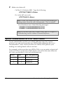
If You Have No SPIDS and Only One DN
Make these modifications when entering your line configuration.
2
Data Channel Service Profile ID
Leave this field blank.
3
Data Channel Directory Number
Enter your DN. Do not include your area code.
7
Analog Device Channel Service Profile ID
Leave this field blank.
8
Analog Device Channel Directory Number
Enter your DN again. Do not include your area code.
10
Switch Protocol Type
Select AT&T 5ESS Custom.
Using the Configuration Manager
6-9
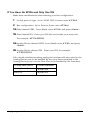
11
Incoming Modem/Fax Call Routing
Select one of the following:
To use
The I-modem routes incoming analog calls
Analog
Device Port
To the Analog Device port (handled by the device
attached to the Analog Device port).
Data Port
To the Data Port (handled by the I-modem).
12
Bus Configuration
Select Point-to-Point.
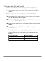
If You Have One SPID and One DN
Make these modifications when entering your line
configuration.
2
Data Channel Service Profile ID
Enter your SPID (up to 20 digits).
3
Data Channel Directory Number
Enter your DN. Do not include your area code.
7
Analog Device Channel Service Profile ID
Enter your SPID (up to 20 digits).
This field should be blank if you have only on SPID.
8
Analog Device Channel Directory Number
10
Switch Protocol Type
Enter your DN. Do not include your area code.
Select AT&T 5ESS Custom.
11
Incoming Modem/Fax Call Routing
Select one of the following:
To use
The I-modem routes incoming calls
To Analog
Device Port
To the Analog Device port (handled by the
device attached to the Analog Device port).
To Data Port
To the Data Port (handled by the I-modem).
12
Bus Configuration
Select Multipoint.
6-10
Courier I-modem Getting Started Guide
Chapter 7
Configuring With
AT Commands
This chapter explains how to configure and test the I-modem using AT
commands and terminal software.
Overview
Configuring the I-modem
Before you can make any calls, you need to configure the I-modem to
work on your ISDN line. If you haven’t ordered an ISDN line, see
Chapter 3, Ordering ISDN Service.
Run your communications software in Terminal mode and then use your
software to send the I-modem AT commands.
What You Should Know
Directory Numbers
Directory Numbers (DNs) take the form of ordinary seven- or ten-digit
telephone numbers. Be sure to leave off the area code from your DN.
Service Profile Identifiers
Service Profile Identifiers (SPIDs) tell the telephone company about any
special services and features to which you've subscribed. SPIDs can be up
to 20 digits long.
Terminal Endpoint Identifier
The TEI is a one or two digit number that permanently identify a your
connection with the central office switch.
Configuring with AT commands
7-1
Preparing to Send AT Commands
1
Get the information from your ISDN service provider that contains
your ISDN phone numbers and central-office switch type.
2
Start your computer and your communications software. Use a
terminal emulation software package, such as HyperTerminal.
3
Put your communications software into Terminal mode.
When your communications software is in Terminal mode, the
commands you type go directly through the serial port to the
I-modem. Refer to the manual for your communications software to
determine how to change to Terminal mode.
4
Set your communications software to use the COM port to which the
I-modem is connected, as well as 8 data bits, no parity, and 1 stop bit.
5
Send the following command (all commands surrounded by angle
brackets, like <Enter>, indicate key presses):
AT <Enter>
If you installed the I-modem and set your communications
software correctly, it sends the following response:
OK
Note: If you don’t get an OK response, refer to Chapter 15,
Troubleshooting, in the I-modem Command Reference.
7-2
Courier I-modem Getting Started Guide
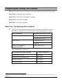
Configuring and Testing Your I-modem
Before you can use your Courier, you must perform the following steps.
Step One: Configure the I-modem
Step Two: Check the I-modem’s settings
Step Three: Save the settings
Step Four: Test the I-modem
Step One: Configuring the I-modem
1
Look over the information you received from your ISDN service
provider to obtain your central-office switch and protocol type.
This switch type
Supports this protocol type
Northern Telecom DMS-100
National ISDN-1 (PVC 2)
Custom (PVC 0 or 1)
AT&T 5ESS
National ISDN-1
Custom∗
Other (for example,
Siemens EWSD)
National ISDN-1
The command is AT*W=n
∗
To set this switch protocol type
Use this command
AT&T 5ESS Custom*
AT*W=0
Northern Telecom DMS-100
AT*W=1
National ISDN-1
AT*W=2
National ISDN-2
AT*W=3
If your switch protocol is AT&T 5ESS Custom, see Special Considerations for AT&T 5ESS Custom on
page 5-7.
Configuring with AT commands
7-3
2
3
Set the appropriate bus configuration.
To set
Use this command
Point to point
AT*M=0
Multipoint
AT*M=1
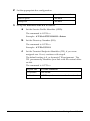
Set up the ANALOG DEVICE B-channel.
a
Set the Service Profile Identifier (SPID).
The command is AT*S1=n
Example: AT*S1=84755511110111 <Enter>
b
Set the Directory Number (DN).
The command is AT*P1=n
Example: AT*P1=5551111
c
Set the Terminal Endpoint Identifier (TEI), if you were
assigned one. If not, continue with step d.
The default setting is 0, or dynamic TEI assignment. The
TEI permanently identifies your link with the central office
switch.
The command is AT*T1=n
7-4
If your TEI
Use this command
Is dynamic
AT*T1=00
Is fixed
AT*T1=n, where n is a number from 1 to 63.
Courier I-modem Getting Started Guide
d
Set the Call Type.
Note: The call type that you choose will apply to outgoing
calls only.
The command is AT*V1=n
4
To set this call type
Use this command
3.1 kHz audio (for modem,
fax, or voice calls)
AT*V1=0
Speech only
AT*V1=1
Set up the DATA B-channel.
a
Set the Service Profile Identifier (SPID).
The command is AT*S2=n
Example: AT*S2=84755511120111
b
Set the Directory Number (DN).
The command is AT*P2=n
Example: AT*P2=5551112
c
Set the Terminal Endpoint Identifier (TEI), if you were
assigned one. If not, continue with step d.
The default setting is 0, or dynamic TEI assignment.
The command is AT*T2=n
If your TEI
Use this command
Is dynamic
AT*T2=00
Is fixed
AT*T2=n, where n is a number from 1
to 63.
Configuring with AT commands
7-5
d
Set the Call Type.
Note: The call type you choose will apply to both
incoming and outgoing calls.
The command is AT*V2=n
To set this call rype
Use this command
Automatic service choice
(Universal Connect)
AT*V2=0
V.120 rate adaption calls only
AT*V2=1
V.110 rate adaption calls only
AT*V2=2
Modem or fax emulation only
AT*V2=3
Clear-channel synchronous calls
only
AT*V2=4
Internet access mode (default)
AT*V2=5
You are done configuring your I-modem.
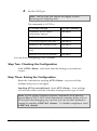
Step Two: Checking the Configuration
Send ATI12 <Enter>, and check that the settings you made are
correct.
Step Three: Saving the Configuration
Reset the I-modem by sending ATZ! <Enter> or power off the
modem and power it on again.
Sending ATZ is not sufficient! Send ATZ! <Enter> Your settings
will not take effect until the I-modem undergoes this type of reset.
Note: If your phone company requires compliance with Bellcore
Special Report NWT 1953, which introduces a random delay of 45 to
65 seconds when bringing up your line, you can set the I-modem to
comply by sending ATS67.4=1 <Enter>. To disable compliance, send
ATS67.4=0 <Enter>.
7-6
Courier I-modem Getting Started Guide
Step Four: Testing the Configuration
1
After you reset your I-modem (in Step Three) watch the I-modem’s
LED status indicators. AA, DTR, MR, RTS, and CTS should be lit
green, and NS should blink yellow rapidly.
Watch the NS LED closely. It should follow this pattern:
Step
The NS LED
Means this
1
Fast blink (8 per
second), Yellow
Searching for U interface
(I-modem Model 1 and 2 only)
2
Slow blink (1 per
second), Yellow
Searching for S/T interface
3
Slow blink (1 per
second), Green
Physical connection active
4
Green solid
Ready to make or receive calls
These are error conditions and suggested solutions:
If NS LED does this
This may be the problem
Red blink (1 per second)
Incorrect SPID. Send ATI12 <Enter>
and re-check your SPID and DN
settings.
Red solid
No physical connection. Make sure
that the U-interface cable is plugged
into the I-modem.
Configuring with AT commands
7-7
2
Make a test data call.
Call the U.S. Robotics BBS. Type the following:
ATDT18477348612 <Enter>
Or, in the 847 area code:
ATDT7348612 <Enter>
Note: When you make ISDN calls, you won’t hear dialing or
training tones when the call is being made. This is normal.
You should see one of the following messages:
CONNECT 56000/ARQ/DIGITAL/V120
CONNECT 64000/ARQ/DIGITAL/V120
Note: If you don’t see one of these codes, refer to Chapter 15,
Troubleshooting, in the I-modem Command Reference.
Special Considerations for AT&T 5ESS Custom
If your central-office switch is an AT&T 5ESS that runs the Custom
protocol, you can use fewer than two SPIDs/DNs, although this is not
recommended. Lines with fewer than two SPIDs/DNs prevent your
making two analog-based calls at one time.
For example, with fewer than two SPIDs/DNs, you can make a digital call
(such as V.120 or synchronous PPP) and a voice call at the same time, but
not a fax/modem and a voice call simultaneously.
SPIDs
7-8
DNs
Bus Configuration
0
1
Point-to-Point
1
1
Multipoint
2
2
Multipoint
Courier I-modem Getting Started Guide
If You Have No SPIDs and Only One DN
Make these modifications when entering your line configuration.
1
Switch protocol type. Set to AT&T 5ESS Custom: enter AT*W=0
2
Bus configuration. Set to Point-to-Point: enter AT*M=0
3a Data channel SPID.
3b Data channel DN.
Leave blank: enter AT*S2= and press <Enter>.
Enter your DN (do not include your area code.
For example, AT*P2=5551111
4a Analog Device channel SPID.
Leave blank: enter AT*S1= and press
<Enter>.
4b Analog Device channel DN.
Enter your DN: for example,
AT*P1=5551111
Also, decide whether incoming analog fax/modem calls are routed to the
Analog Device port (to be handled by the voice device attached to the
Analog Device port) or to the Data Port (to be handled by the I-modem).
To route these calls to
Use this command
Analog Device Port
ATS67.3=0
Data Port
ATS67.3=1
Configuring with AT commands
7-9
If You Have One SPID and One DN
Make these modifications when entering your line configuration.
1
Switch protocol type. Set to AT&T 5ESS Custom: type AT*W=0
<Enter>.
2
Bus configuration. Set to Multipoint: type AT*M=1 <Enter>.
3a Data channel SPID.
Enter your SPID (up to 20 digits): for example,
type AT*S2=84755511110111 <Enter>.
3b Data channel DN.
Enter your DN (do not include your area code.
For example, AT*P2=5551111 <Enter>.
4a Analog Device channel SPID.
Leave blank: enter AT*S1= and press
<Enter>..
4b Analog Device channel DN.
Enter your DN: for example,
AT*P1=5551111 <Enter>.
Also, decide whether incoming analog fax/modem calls are routed to
the Analog Device port (to be handled by the device attached to the
Analog Device port) or to the Data Port (to be handled by the Imodem).
7-10
To route calls to the
Use this command
Analog Device Port
ATS67.3=0
Data Port
ATS67.3=1
Courier I-modem Getting Started Guide
Chapter 8
Configuring Your Courier
For Windows 95
This chapter explains how to:
•
•
•
Configure your I-modem for use with Plug and Play
Obtain and install the latest I-modem files
Configure Dial-Up Networking to access your ISP
Overview
The first time you start Windows 95 after you’ve installed your Courier,
Windows 95 auto-detects your Courier. Since Windows 95 supports Plug
and Play, most installations are trouble-free.
Note for external Courier users: You must power on your
I-modem before you start Windows 95, or Windows 95 will not recognize
your I-modem.
What You Need
You need Windows 95 with Dial-Up Networking installed to configure
your I-modem for Windows 95.
Configuring Your Courier With Plug and Play
Plug and Play mode allows Windows 95 to automatically detect your Imodem and determine which modem configuration file (called an INF
file) to use.
Note for internal Courier users: If you do not want to use the Plug and
Play mode of your operating system, you must manually change the
jumpers on the modem to the desired COM port/ IRQ settings. For
information about setting jumpers for different COM ports and IRQ
settings, see Chapter 12, Configuring Your Courier With DIP Switches and
Jumpers.
Windows 95
8-1
Follow the steps below to install I-modem INF file for Windows 95:
8-2
1
Power on your computer and start Windows 95. Your computer
detects new hardware and displays the following window:
2
Select Driver from disk provided by hardware manufacturer and
click OK to install the INF file that is provided on the root directory
(D:\ or the correct path of your CD-ROM) of the Connections CDROM.
Courier I-modem Getting Started Guide
3
When the following window appears, insert your Connections CDROM, change the default drive (A:\) in “Copy Manufacturer’s files
from” to D:\ (or the correct path of your CD-ROM) and click OK to
install the INF file.
Windows 95 displays the following window asking you to choose
your I-modem type from the list:
4
Select the Courier I-modem with ISDN & V.34 PC (Internal) or
Courier I-modem with ISDN & V.34 (External) from the list and click
OK.
Your I-modem is now ready to use!
Windows 95
8-3
Files Needed By Your I-modem
For your I-modem to work most efficiently,
U.S. Robotics recommends that you use the latest version of the following
two files from the U.S. Robotics web site (http://totalservice.usr.com) or
ISDN (847.734.8612) or analog (847.982.5092) BBS.
8-4
This file
Does this
The I-modem
software
Contains software that contains new feature
updates
The INF file
Helps your computer work more effectively
with your I-modem
Courier I-modem Getting Started Guide
Installing the Latest I-modem Software
See your I-modem Command Reference Manual for information about
upgrading your Courier’s software.
Accessing Your Internet Service Provider
This section explains how to set up your I-modem to access the Internet
using Windows 95 Dial-Up Networking. You can also use Dial-Up
Networking to access Internet Service Providers (ISPs) or remote LANs.
To access your ISP or a remote LAN, you must do the following:
Step One: Determine if Dial-Up Networking is installed.
Step Two: Install Dial-Up TCP/IP support.
Step Three: Set up a connection to your ISP.
Step Four: Customize TCP/IP settings (if necessary).
Step One: Determine if Dial-Up Networking is Installed
1
Click Start | Settings | Control Panel.
2
On the Control Panel, double-click on Network to
display the Network Window.
Windows 95
8-5
3
8-6
If Dial-Up Networking
Do this
Is listed
Go to the section “Installing TCP/IP
Support” to install Dial-Up
Networking.
Is not listed
Go to Step 3.
Return to the Control Panel and double-click on
Add/Remove Programs to open the
Add/Remove Programs Properties window:
Courier I-modem Getting Started Guide
4
Click Windows Setup tab.
Windows 95
8-7
8-8
5
Double-click on Communications to display the Communications
window:
6
Click on Dial-Up Networking to check the box.
7
Click OK | OK.
8
Insert your Windows 95 Setup diskette or CD-ROM when you are
prompted, and Windows 95 installs Dial-Up Networking.
Courier I-modem Getting Started Guide
Step Two: Installing Dial-Up TCP/IP Support
1
Click Start | Settings | Control Panel.
2
On the Control Panel, double-click on the
Network icon to display the following window:
Determine if the TCP/IP Dial-Up Adapter is installed:
IF TCP/IP ->
Dial-Up
Adapter
Do this
Is not listed
Click Add… | Protocol | Microsoft | TCP/IP
| OK.
Insert your Windows 95 Setup diskette or CDROM when you are prompted, and
Windows 95 installs TCP/IP protocol
Windows 95
8-9
support.
Is listed
8-10
Read the section “Customize the TCP/IP
Settings”
Courier I-modem Getting Started Guide
Step Three: Setting Up a Connection to Your ISP
1
Click Start | Programs | Accessories | Dial-Up Networking.
2
Double-click Make New Connection.
3
Select the correct Courier modem, if not already
selected.
4
Type a name for the connection and click Next .
Windows 95
8-11
8-12
5
Type a phone number for the connection and click Next .
6
You should see a message indicating that a new connection was
created successfully.
Courier I-modem Getting Started Guide
7
Click Finish.
8
On the Dial-Up Networking window, move your cursor to the new
icon you have just created and click the right mouse button. Select
Properties on the menu to display the following window:
8
On the My Connection window, click Server Type…, and deselect the
following:
•
•
•
9
Log on to Network
NetBEUI
IPX/SPX Compatible
Click OK, and OK.
Windows 95
If your ISP
Do this
Gives you specific IP or server
addresses
Go to Step Four: Customizing
TCP/IP Settings
Does not give you specific IP or
server addresses
Double-click on the icon you
just created to dial your ISP.
8-13
Step Four: Customizing the TCP/IP Settings
Depending on the ISP you use, you may need to customize the TCP/IP
settings. Contact your ISP for specific information, such as IP address, or
domain name servers (DNS).
8-14
1
Click My Computer and double-click Dial-Up Networking icon to
display all the connections you can customize.
2
Right-click the icon you created and select
Properties to display the My Connection
window.
Courier I-modem Getting Started Guide
3
On the My Connection window, click Server Type to display the
TCP/IP Settings window.
4
Specify an IP address, if needed:
Windows 95
If your ISP
Do this
Gives you a specific IP address
Click Specify an IP address
and enter the IP address
provided by your ISP
Does not give you a specific IP
address
Click Server assigned IP
address
8-15
5
6
8-16
After you specify an IP Address, specify server assigned server
addresses, if needed:
If your ISP
Do this
Gives you specific server
addresses
Click Specify name server
addresses and enter the server
address(es) provided by your
ISP
Does not give you specific
server addresses
Click Server assigned server
address
Double-click your New Connection icon to connect!
Courier I-modem Getting Started Guide
Chapter 9
Configuring Your
I-modem For Macintosh
This chapter explains how to configure your I-modem for use with
Macintosh computers.
Handshaking Cable
Use a hardware handshaking cable to connect your I-modem to the
Macintosh.
System Configuration
Also, if you aren’t using AppleTalk® Remote Access (ARA), set
AppleTalk to Inactive (in Chooser).
The modem initialization string should be AT&F1&D0.
For instructions about how to set up your Macintosh communications
software package, visit the U.S. Robotics Totalservice web site at
http://totalservice.usr.com.
Accessing the Internet
Accessing the Internet through an ISP requires the following software:
•
•
MacTCP or Open Transport (TCP/IP from the Control Panels menu),
which has probably already been installed on your Macintosh
SLIP or PPP dialing software
Note: You can find public domain PPP dialers (such as MacPPP and
FreePPP) on the Internet.
Macintosh
9-1
Configuring MacTCP
1
Open the MacTCP control panel.
2
Click PPP and More…
3
In Obtain Address group box, click Server.
4
In Domain Name Server Information, enter the domain name and IP
address for one or more domain name servers.
Note: If you don’t have domain name server information, contact your
ISP.
When you’re finished configuring MacTCP, restart your Macintosh.
Installing MacPPP Dialer
When you install MacPPP for the first time, a PPP icon appears in the
MacPPP folder. Put the PPP icon in the Extensions Folder, in the System
Folder, and restart your Macintosh.
9-2
Courier I-modem Getting Started Guide
Configuring ConfigPPP Dialer
1
ConfigPPP is your PPP dialer.
2
Open ConfigPPP and click New...
3
Enter your Port Name and click OK.
4
Click Config… and set your Port Speed (the fastest speed for MacPPP
is 57.6 kbps), phone number, and modem initialization string.
5
Click Authentication… and enter the user name and password your
ISP assigned you.
6
Click Done.
Dialing With ConfigPPP
In Config PPP, click Open. Config PPP dials your ISP and establishes
your PPP connection.
Macintosh
9-3
9-4
Courier I-modem Getting Started Guide
Chapter 10
Configuring Your I-modem
for Other Operating Systems
This chapter explains how to configure your I-modem for:
•
•
•
•
•
Windows 3.x
Windows NT
MS-DOS
OS/2
UNIX, Linux, or AIX
If You Are Using Windows 3.x
Windows 3.x comes with a built-in communications software package,
Windows Terminal. You can use Windows Terminal to test your I-modem
or you can install the communications software package that is included
on the Connections CD-ROM.
Because Windows Terminal only supports speeds up to 19200 bps, it is
recommended that you use a third-party communications software
package.
For instructions about how to set up your Windows 3.x communications
software package, visit the U.S. Robotics Totalservice web site at
http://totalservice.usr.com.
Other Operating Systems
10-1
If You Are Using Windows NT 4.0
What You Need
You need Windows NT with Remote Access Service (RAS) installed to
configure your I-modem for Windows NT.
Configuring Your I-modem
To obtain and install the I-modem INF file for Windows NT, follow the
same steps as Windows 95 users.
Installing the Latest I-modem Software
After you obtain the latest I-modem INF file, copy it to the
C:\WINNT\INF subdirectory.
For more information about Windows NT, see the Windows NT
documentation or visit the U.S. Robotics Totalservice web site at
http://totalservice.usr.com.
10-2
Courier I-modem Getting Started Guide
If You Are Using MS-DOS
Because there is no communications software built in to MS-DOS, you
must install and run a third-party communications software package to
operate your I-modem.
RapidComm, which is included on the Connections CD-ROM, contains
MS-DOS and Windows 3.1 versions of RapidComm.
You must choose the COM port to which your I-modem is attached in
whatever communications software package you are using.
For instructions about how to set up your MS-DOS communications
software package, see the software documentation or visit the U.S.
Robotics Totalservice web site at http://totalservice.usr.com.
For Internal Couriers Only
You must choose the COM port, IRQ, and the I/O address within the
communications software that you use. These are the standard I/O
address and IRQ settings for each COM port:
COM Port
I/O Address
IRQ
COM1
03F8
IRQ4
COM2
02F8
IRQ3
COM3
03E8
IRQ4
COM4
02E8
IRQ3
Other Operating Systems
10-3
If You Are Using OS/2
Replace the standard OS/2 serial port drivers COM.SYS and VCOM.SYS
with SIO.SYS and VSIO.SYS. You can get these enhanced drivers from the
U.S. Robotics web site.
For instructions about how to set up your OS/2 communications software
package, visit the U.S. Robotics Totalservice web site at
http://totalservice.usr.com.
For Internal Couriers Only
These are the standard I/O address and IRQ settings for each COM port:
COM Port
I/O Address
IRQ
COM1
03F8
IRQ4
COM2
02F8
IRQ3
COM3
03E8
IRQ4
COM4
02E8
IRQ3
Nonstandard COM/IRQ settings are done by adding switches (command
line parameters) to the COM.SYS (or SIO.SYS) line in CONFIG.SYS.
For example, to select COM3 and IRQ5, enter the following command
line:
\OS2\BOOT\COM.SYS /i5/c3
10-4
Courier I-modem Getting Started Guide
If You Are Using UNIX, Linux, or AIX
Linux has a built-in communications software package called minicom.
You can obtain minicom on the U.S. Robotics FTP site (ftp.usr.com) in the
usr/bin directory.
For instructions about how to set up your UNIX®, Linux, or AIX
communications software package, visit the U.S. Robotics Totalservice
web site at http://totalservice.usr.com.
These are the standard port names and settings:
Outgoing Calls
Incoming Calls
Port
IRQ
I/O Address
/dev/cua0
/dev/ttyS0
COM1
4
03F8
/dev/cua1
/dev/ttyS1
COM2
3
02F8
/dev/cua2
/dev/ttyS2
COM3
4
03E8
/dev/cua3
/dev/ttyS3
COM4
3
02E8
Use the setserial command to tell Linux about any nonstandard
COM/IRQ combinations that you may have set using your Courier’s
jumpers. Setserial also selects serial port speed and I/O port address.
Other Operating Systems
10-5
10-6
Courier I-modem Getting Started Guide
Chapter 11
Configuring TurboPPP
With AT Commands
This chapter explains how to control TurboPPP with AT commands.
Overview
TurboPPP allows your I-modem to use both B-Channels to send and
receive data over the ISDN.
TurboPPP includes the following features:
This feature
Allows the I-modem to
PPP/ML-PPP (Multilink
PPP)
Accept PPP/ML-PPP calls
Dynamic Data Bandwidth
Allocation (DBA)
Save money by only using the second
B-channel when it is need for data
transfers, and then dropping the second
B-channel when it is not needed
Point to Point Protocol (PPP) / ML-PPP
Your Courier I-modem now supports Originate and Host Mode PPP/
ML-PPP. Host Mode ML-PPP allows you to set the I-modem to accept
ML-PPP calls. Originate Mode allows PPP/ML-PPP calls to be made from
the I-modem.
Determining TurboPPP Settings
To do this
Use this command
Obtain an overview of TurboPPP
settings
ATI16
Configuring with AT commands
11-1
Setting PPP/ML-PPP Host and Originate Mode
Use the following *P settings to control PPP/ ML-PPP:
To do this
Use this
setting
Or these settings
Set all PPP-related
default values
*P=0
*V2=5, S68.2=0, S68.3=0,
S68.6=0, S69.1=0, *D1=2,
*D2=24 *D3=90, *D4=44, *K=1
Set Asynchronous to
Synchronous PPP
Set Single Link
TurboPPP
Set ML-PPP
*P=1
S68.2=1
*P=2
S68.2=0, S68.3=1
*P=3
S68.2=0, S68.3=0 (default)
Note: Before you can use this feature you must enable
PPP/ ML-PPP using *V2=5.
Making Calls With ML-PPP
You can make ML-PPP calls with any PPP dialer.
Making an Outgoing ML-PPP Call
When making an outgoing ML-PPP call, enter the number of the host. If
the phone number for two calls is different, you must enter both of them.
They must be separated by an ‘&’ as shown below. If only one phone
number is given, the same number will be dialed for both calls.
Making an Incoming ML-PPP Call to Your I-modem
When someone attempts to call your I-modem using ML-PPP, they must
call the Data number first and the Voice number second.
See the following figures for an example of phone numbers with and
without ML-PPP using Windows 95. These rules apply when using
terminal programs with other operating systems.
11-2
Courier I-modem Getting Started Guide
Regular Connection Without ML-PPP
Connection With ML- PPP
Configuring with AT commands
11-3
Dynamic Data Bandwidth Allocation
Dynamic Data Bandwidth Allocation is a cost savings feature that helps
you save money by only using the second B-channel when it is need for
data transfers, and then dropping the second B-channel when it is not
needed. Dynamic Bandwidth Allocation determines the need for the
second B-channel by measuring the amount of data sent or received
during a set period of time.
Dynamic Data Bandwidth Allocation settings (*D0, *D1, *D2, *D3, and
*D4) determine under which conditions the second link should be brought
up or down.
If you enter a value in
TurboPPP does this
*D3 that is more than the time set in *D1
Brings up the second link
*D4 that is less than the time set in *D2
Brings down the second link
Important: Dynamic Bandwidth Allocation is set on by default. To turn
off Dynamic Bandwidth Allocation, use *D0=1.
Controlling Dynamic Bandwidth Allocation in ML-PPP
Use the following *D0 settings to control Dynamic Bandwidth Allocation:
To do this
Use this setting
Or this setting
Enable Dynamic Bandwidth
Allocation in ML-PPP (default).
*D0=0
S68.6=0
Disable Dynamic Bandwidth
Allocation in ML-PPP
*D0=1
S68.6=1
Use the following settings to control the period of time your
I-modem samples the throughput in order to determine if the second link
needs to be brought up or down:
11-4
To set the period of time your
I-modem samples througput
to determine
Use this setting
Example
If a second link should be
brought up
*D1=n, where n
equals 1-255 five
second units
*D1=2 (ten
seconds)
If a second link should be
brought down
*D2=n, where n
equals 1 -255 five
second units
*D2=10 (50
seconds)
Courier I-modem Getting Started Guide
Setting When the Second Link Comes Up
Use the following *D3 setting to determine when the I-modem should
bring up a second link:
To do this
Use this setting
Example
Determine when the second
link should be brought up,
based on the level of
utilization of the existing link
*D3=n, where n equals
1 -100%
*D3=90
(90%)
Setting When the Second Link Comes Down
Use the following *D4 setting to determine when the I-modem should
bring down a second link:
To do this
Use this setting
Example
Determine when the second
link should be brought
down, based on the level of
utilization of the existing link
*D4=n, where n
equals 1-100%
*D4=44
Enabling the Tone When the Second Link Comes Up
Use the following *T settings to enable the tone when the I-modem brings
up a second link:
To do this
Use this setting
Or this setting
Enable tone when second link
is brought up (default)
*T=0
S69.1=0
Disable tone when second link
is brought up
*T=1
S69.1=1
Configuring with AT commands
11-5
Using Compression in TurboPPP mode
Courier I-modem supports the following three types of compression
modes in TurboPPP.
Pass-through Compression
Pass-through compression allows the terminal applications running on
each PC on both ends of the connection to perform compression. Using
this form of compression, the Courier I-modem does not perform
compression.
Pass-through compression allows for maximum compression by
eliminating the serial port bottleneck.
Auto Mode Compression
Auto Mode Compression allows the I-modem to negotiate compression if
your application cannot negotiate compression. This is the default.
Turbo Mode Compression
Turbo Mode Compression allows the I-modem to negotiate compression
with the remote host and disable compression between the I-modem and
your application.
Setting Modes of Compression
Use the following *K settings to use compression in TurboPPP mode:
Use this mode of compression
Use this setting
Pass-through Mode
*K0
Auto Mode (Default)
*K1
Turbo Mode
*K2
U.S. Robotics recommends that you enable the compression in your
application software and keep compression set to &K1 (default).
Note: Under Auto Mode Compression (&K1), the I-modem allows your
application to negotiate compression. If you have enabled compression in
your application and the application successfully negotiates compression,
then the I-modem switches to Transparent Mode compression and allows
your application do data compression.
11-6
Courier I-modem Getting Started Guide
I-modem supports a 230 kbps DTE rate using ML-PPP.
Configuring with AT commands
11-7
11-8
Courier I-modem Getting Started Guide
Chapter 12
Configuring Your I-modem
With DIP Switches and Jumpers
This chapter explains how to:
•
•
•
Locate DIP switches
Configure with DIP switches
Configure with jumpers (internal I-modem only)
DIP Switches on the External I-modem
Locating DIP Switches
On the external I-modem, the DIP switches are on the bottom of the unit.
DIP Switches
Figure 8.1 DIP Switches on the External Courier
Default DIP Switches (Model U)
Here are the default settings for the Model U I-modem:
To do this
Load &FO settings upon reset
Set DIP
Switch
1
Load NVRAM settings upon reset
Ignore AT commands
Enable AT commands
To this setting
OFF
ON(Default)
2
OFF
ON (Default)
Note: On the Model U, DIP switches 3 and 4 are unused.
DIP Switches and Jumpers
12-1
12-2
Courier I-modem Getting Started Guide
Default DIP Switches (Model U, V.35)
The V.35 interface is provided so that you can connect the I-modem to a
bridge, router, or multiplexer, as a replacement or backup for a CSU/DSU
and leased lines.
To change the setting to V.35, flip the DIP switches on the bottom of the
I-modem to the following positions (DIP switches 1 and 2 aren’t shown in
the figure because their settings are not relevant):
Figure 8.2 Default DIP Switches for the External Model U Courier
Default DIP Switches (Model S/T)
If you have Model S/T, the default DIP switches are the same as in figure
8.2.
In addition, there are additional default settings: DIP switch 1 and 2 are
set ON. DIP switch 3 through 12 are set OFF.
Use the following chart to set termination on the Model S/T.
To set this termination
Set these DIP switches
0 Ohm termination
9 through 12 OFF
50 Ohm termination
9 and 11 OFF
10 and 12 ON
100 Ohm termination
9 and 11 ON
10 and 12 OFF
DIP Switches and Jumpers
12-3
DIP Switches on the Internal I-modem
Locating DIP Switches
On the internal I-modem, the DIP switches are on the end of the unit.
DIP Switches
Figure 8.5 DIP Switches on the Internal Courier
Default DIP Switches
DIP switches 1 and 2 are set ON. DIP switches 3 and 4 are unused.
12-4
Courier I-modem Getting Started Guide
Using DIP Switches to Configure Your I-modem
To do this
Set DIP
Switch
Load &FO settings upon reset
1
Load NVRAM settings upon reset
Ignore AT commands
OFF
ON(Default)
2
Enable AT commands
To this setting
OFF
ON (Default)
Note: DIP switches 3 and 4 are unused.
Jumpers on the Internal I-modem
Locating Jumpers
Your internal I-modem is set to Plug and Play. You shouldn’t have to
change this setting, however, if you have multiple devices connected to
your system, you may need to change the jumper settings to avoid
hardware conflicts.
Jumpers
Figure 8.8 Jumpers on the Internal Courier
DIP Switches and Jumpers
12-5
Changing Jumper Settings
You can add shunts (see figure 8.9) to cover sets of pins on the jumper
blocks (see figure 8.8).
Caution: If you do not have any hardware conflicts, you do not need to
use this section.
To change jumper settings, use tweezers or needle-nosed pliers and gently
rock the jumper back and forth as you lift.
IRQ block
COM port block
Figure 8.9 Jumper Blocks Without Shunts
Figure 8.10 Shunt
Note: Do not grasp the shunts too firmly. If you grasp them too firmly,
you may crush the shunt or damage the modem.
12-6
Courier I-modem Getting Started Guide
Setting Jumpers for a Specific COM Port or IRQ
To set your modem to
To set the COM port jumpers to
COM 1
COM 2
COM 3
COM 4
Plug and Play
Setting Jumpers for a Specific IRQ
To set your modem to
To set the IRQ jumpers to
IRQ 2
IRQ 3
IRQ 4
IRQ 5
IRQ 7
DIP Switches and Jumpers
12-7
Chapter 13
Viewing LEDs
This chapter explains how to view the twelve LEDs on the front of your external
I-modem.
B1
B2
AA
CD
NS
RD
SD
DTR
MR
RTS
CTS
SYNC ARQ/
FAX
with ISDN/V.34
This LED
Status
Means your I-modem
B1
Green blink
(8/sec)
Digital call connected at 64 or 56 kbps.
Green blink
(1/sec)
Analog modem or fax call connected.
Green
Voice call connected.
Off
Not connected.
Green blink
(8/sec)
Digital call connected at 64 or 56 kbps.
Green blink
(1/sec)
Analog modem or fax call connected.
Off
Not connected.
On
Will auto answer calls
Blinking
Has detected an incoming call
Off
Will not auto answer calls
On
Has detected a carrier from a remote device or carrier-detect has
been forced on
Off
Has not detected a carrier
B2
AA
CD
Viewing LEDs
13-1
This LED
Status
Means your I-modem
NS
Green
Line ready
Green blink
(1/sec)
S/T-interface OK, but line not yet ready
Red blink
Incorrect SPID
(1/sec)
RD
SD
DTR
MR
RTS
CTS
SYNC
ARQ/FAX
13-2
Amber blink
(1/sec)
Looking for S/T-interface
Red
U-interface not found (I-modem Model U)
Amber blink
(8/sec)
Looking for U-interface (I-modem Model U)
Off
The I-modem does not have control of the line.
Flashing
Is sending data to your computer
Off
Is idle
Flashing
Is receiving data from your computer
Off
Is idle
On
Has received a Data Terminal Ready (DTR) signal from your
computer
Off
Has not detected DTR
On
Configurable. See Command Reference Manual
Flashing
Is retraining with a remote device or is in Test mode
Off
Configurable. See Command Reference Manual
On
Has detected the Request to Send (RTS) signal from your
computer
Off
Has not detected the RTS signal from your computer
On
Is sending your computer the Clear to Send (CTS)
Off
Is not sending your computer the CTS signal
On
Is in synchronous mode
Blinking
Has activated Dial Security
Off
Is not in synchronous mode/Dial Security not active
On
Is using V.42 bis error correction
Flashing
Is retransmitting data to the remote modem
Blinking
Is in fax mode
Off
Is not using error control, not retransmitting data, and not faxing
Courier I-modem Getting Started Guide
Viewing LEDs
13-3
Chapter 14
Using x2
Use this chapter to:
•
•
Determine if your I-modem has x2 enabled
Use the new features
Enhanced x2 Features
Your I-modem with x2™ has new result codes and the following new
features.
To do this
Use this command
Detemine if x2 is enabled in your modem
ATI7
Disable or enable x2
ATS58
Limit the upper speed limit of an x2
connection
AT&N
Limit the lower speed limit of an x2
connection
AT&U
Note: New x2 features should be transparent to most users. If you are an
advanced user, see the sections ”Controlling x2” and “Controlling Link
Speeds with &N and &U” later in this chapter for detailed information
regarding these features.
14-1
Using x2
How to Tell if x2 is Enabled in Your I-modem
If you aren’t sure whether x2 is enabled in your I-modem, use the ATI7
command to display product configuration information. If x2 is enabled
on your I-modem, the following information displays:
USRobotics I-modem Configuration Profile...
Copyright, 19xx-96, U.S. Robotics. All rights reserved.
Product type
US/Canada External
Options
HST,V32bis,Terbo,VFC,V34+,x2
Fax Options
Class 1,Class 2.0
Clock Freq
{Clock Frequency}
Eprom
256k
Ram
32k
Supervisor date
{Date}
DSP date
{Date}
Supervisor rev
{x.x.x}
DSP rev
{x.x.x}
Serial Number
{serial number}
OK
Note: Dates, serial numbers, revision numbers, and Clock Frequencies
may vary. The most important line is the “Options” line, which lists
support for x2.
Obtaining x2
For information about how x2 works, visit the x2 web site at
http://www.usr.com/x2
Courier I-modem Getting Started Guide
14-2
How x2 Works
For information about how x2 works, visit the x2 web site at
http://www.usr.com/x2
Controlling x2
The I-modem allows you to communicate using x2 Server Mode and x2
Symmetric Mode.
x2 Server Mode
Using x2 Server Mode, you can accept calls from x2 client modems.
Using this mode, the x2 client modem that connects to your I-modem can
receive data at speeds up to 56 kbps and send data at V.34 speeds.
x2 Symmetric Mode (Host Mode)
Using x2 Symmetric Mode, your I-modem can connect at speeds of 56 or
64 kbps in both directions over a 3.1 kHz voice call (*V2=3). For x2
Symmetric Mode to work, our I-modem must connect to a modem using
x2 Symmetric Mode, such as another I-modem.
Note: In some areas, 3.1 kHz voice calls over ISDN are cheaper than data
calls.
Use the following S58 settings to control x2:
To do this
Use this command
Disable x2
S58.0=1
Force A-law mode
S58.2=1
Disable Symmetric Mode
S58.3=1
Note: A-law is required in all countries but the United States, Canada,
Japan, Taiwan, and Hong Kong. If you are using your
I-modem in one of these countries, do not force A-law mode.
Controlling Link Speeds with &N and &U
You can use the &N and &U commands to control link speeds. Couriers
without x2 can still use the &N and &U commands, but can only control
link speeds up to 33.6 kbps.
14-3
Using x2
Controlling Link Speeds
You can use the &N and &U commands to control the link speeds of your
I-modem with x2. Use the following table to determine how to use &N
and &U commands:
To limit the
Use
Highest possible connect speed
&N
Lowest possible connect speed
&U
Range of possible connect speeds
&N and &U
Table 14.1 Using Link Speeds
Note: The default values for &N and &U are 0. If you change these values,
you will limit the speeds at which you can connect. U.S. Robotics
recommends that you do not alter these values.
Limiting the Highest Possible Connect Speed
The &N command allows you to limit the highest possible connect speed.
If a remote modem attempts to connect to your Courier with x2 at a speed
higher than &N, your Courier with x2 will not allow it to connect.
To limit the
Use this command
Where x is
Highest possible
connect speed
AT&N=x
A value from 0 to 32
Courier I-modem Getting Started Guide
14-4
Limiting the Lowest Possible Connect Speed
The &U command allows you to limit the lowest possible connect speed.
If a remote modem attempts to connect to your Courier with x2 at a speed
lower than &U, your Courier with x2 will not allow it to connect.
To limit the
Use this command
Where x is
Lowest possible
connect speed
AT&U=x
A value from 0 to 32
Limiting a Range of Possible Connect Speeds
By setting &N and &U values, you can limit the range of speeds at which
your Courier with x2 connects. If a remote modem does not connect to
your Courier with x2 at a range between the speeds designated by the &N
and &U commands, your Courier with x2 will not allow it to connect.
Note: The link speed associated with the &U argument cannot be greater
than the link speed associated with &N argument.
Use the following table to understand the relationship between &U and
&N commands:
If &U
And &N
Then your modem
Equals
zero
Equals zero
Connects at the highest possible
speed.
Is greater than
zero
Connects at the &N speed only.
Is greater than
zero and greater
than &U
Connects at the highest possible
speed in the range from &U to &N.
Is greater
than zero
Table 14.2 Constraints on Link Speed
14-5
Using x2
&N and &U Command Values
Use the following table for a complete list of &N and &U link speeds and their
associated indexes:
Link
Speed
Index
Link
Speed
Index
Link
Speed
Index
Highest
0
21600
11
45333
22
300
1
24000
12
46666
23
1200
2
26400
13
48000
24
2400
3
28800
14
49333
25
4800
4
31200
15
50666
26
7200
5
33600
16
52000
27
9600
6
33333
17
53333
28
12000
7
37333
18
54666
29
14400
8
41333
19
56000
30
16800
9
42666
20
57333
31
19200
10
44000
21
64000
32
Table 14.3 Link Speeds and Indexes
Note: For x2-mode links, &N and &U are used to constrain the speed of the
higher speed direction of the link.
Courier I-modem Getting Started Guide
14-6
Troubleshooting x2 Client Connections
Use the chart below to understand issues affecting your I-modem with x2 and
how to fix them:
This may be the issue
Do this
x2 may not be enabled
on your Courier.
See the section “How to Tell if x2 is Enabled” (Use
the ATI7 command)
Several conditions
may exist.
Use the ATI11 command and check the “x2 status”
field for more information.
If this message
appears
You cannot use x2 because
“Multiple CODECS
in channel”
There are multiple analogto-digital conversions on
the channel.
“Remote modem is
not x2”
The remote modem does
not support x2.
“Channel is x2capable but feature
is not installed”
You have not purchased x2.
Your Courier may be
connected to the
public network via a
PBX or other
telephone equipment
with analog-to-digital
and digital-to-analog
conversions.
Contact your telephone equipment vendor for
information about obtaining pure analog service.
There is another issue.
Do the following:
Due to extra analog-to-digital conversions
performed by some PBX’s and other telephone
equipment, x2 client modems may not be able to
make x2 connections.
•
Visit the U.S. Robotics x2 Web Site at
http://totalservice.usr.com
•
Contact U.S. Robotics Technical Support at
800.231.8770
This should only be used by client modems (such as Sportster or Courier) that
are attempting to connect to your I-modem.
14-7
Using x2
New x2 Result Codes
Use the following table for a list of all result codes, including new x2
result codes:
Numeric
Alphanumeric
180
CONNECT 33333
181
CONNECT 33333/ARQ
182
CONNECT 33333/x2
183
CONNECT 33333/ARQ/x2
184
CONNECT 37333
185
CONNECT 37333/ARQ
186
CONNECT 37333/x2
187
CONNECT 37333/ARQ/x2
188
CONNECT 41333
189
CONNECT 41333/ARQ
190
CONNECT 41333/x2
191
CONNECT 41333/ARQ/x2
192
CONNECT 42666
193
CONNECT 42666/ARQ
194
CONNECT 42666/x2
195
CONNECT 42666/ARQ/x2
196
CONNECT 44000
197
CONNECT 44000/ARQ
198
CONNECT 44000/x2
199
CONNECT 44000/ARQ/x2
200
CONNECT 45333
201
CONNECT 45333/ARQ
202
CONNECT 45333/x2
203
CONNECT 45333/ARQ/x2
204
CONNECT 46666
205
CONNECT 46666/ARQ
206
CONNECT 46666/x2
Courier I-modem Getting Started Guide
14-8
New x2 Result Codes (Continued)
Numeric
14-9
Alphanumeric
207
CONNECT 46666/ARQ/x2
208
CONNECT 48000
209
CONNECT 48000/ARQ
210
CONNECT 48000/x2
211
CONNECT 48000/ARQ/x2
212
CONNECT 49333
213
CONNECT 49333/ARQ
214
CONNECT 49333/x2
215
CONNECT 49333/ARQ/x2
216
CONNECT 50666
217
CONNECT 50666/ARQ
218
CONNECT 50666/x2
219
CONNECT 50666/ARQ/x2
220
CONNECT 52000
221
CONNECT 52000/ARQ
222
CONNECT 52000/x2
223
CONNECT 52000/ARQ/x2
224
CONNECT 53333
225
CONNECT 53333/ARQ
226
CONNECT 53333/x2
227
CONNECT 53333/ARQ/x2
228
CONNECT 54666
229
CONNECT 54666/ARQ
230
CONNECT 54666/x2
231
CONNECT 54666/ARQ/x2
232
CONNECT 56000
Using x2
New x2 Result Codes (Continued)
Numeric
Alphanumeric
233
CONNECT 56000/ARQ
234
CONNECT 56000/x2
235
CONNECT 56000/ARQ/x2
236
CONNECT 57333
237
CONNECT 57333/ARQ
238
CONNECT 57333/x2
239
CONNECT 57333/ARQ/x2
240
CONNECT 64000
241
CONNECT 64000/ARQ
242
CONNECT 64000/x2
243
CONNECT 64000/ARQ/x2
Table 14.4 New Result Codes
There is a complete list of result codes in your
I-modem Command Reference.
Courier I-modem Getting Started Guide
14-10
Appendix A
Other I-modem Features
This chapter explains how to use new features not covered in the Courier
I-modem Command Reference manual.
Data Over Voice
Data Over Voice (DOV) is a feature that allows the I-modem to make
more cost effective 3.1 kHz analog calls while allowing the I-modem to
send digital data at 56 kbps.
Note: DOV is becoming widely used due to the fact that Regional Bell
Operating Companies usually charge less for analog calls than digital
calls. DOV allows users to pay a lower fee while taking advantage of the
digital transmission.
Protocols Supported by Data Over Voice
You can use Data Over Voice with V.120 and Multilink PPP calls.
Configuring Data Over Voice
Use the following *V2 settings to control Data Over Voice:
To force
Use these commands
V.120 DOV calls
*V2=0 and S69.5=1
Multilink PPP DOV calls
*V2=5 and S69.5=1 and the usual
PPP setting
Incoming analog Multilink PPP
calls through the data port
*V2=5, S69.5=1 and S67.2=1 and
the usual PPP setting
Other I-modem Features
A-1
Period Dial Modifier
The period (‘.’) dial modifier is used to send DTMF tones after the
telephone number is dialed. The period dial modifier can be used with
the comma (',') dial modifier to insert delay between the numbers as
appropriate for the application. A typical application for the period dial
modifier is use with PBX systems.
Example: ATDT18479335200.980234
In this example, 18479335200 will be dialed using ISDN signaling, then
980234 will be dialed using in band DTMF signaling.
PCSDL vs. XMODEM
In certain situations, such as running under a multitasking OS such as
Microsoft Windows 95, you may experience difficulty performing a
software download using PCSDL. As a result, U.S. Robotics recommends
using PCSDL under DOS only or performing software download using
the XMODEM file transfer protocol as described in the Courier I-modem
Command Reference in section 17-2.
230 kbps DTE Rate Under Windows®
If you are using a Windows® 95 terminal program, you will be unable to
set your transmission speed to 230 kbps.
230 kbps in Internal I-modems
The I-modem operates at 230 kbps when appropriate regardless of the
transmission speed setting.
Note: Windows does not display the actual data rate for internal
I-modems.
230 kbps in External I-modems
To take advantage of the 230 kbps data rate, you may need to purchase a
high speed (230 kbps) serial card.
Note: Depending on the serial card you purchase, the actual data rate
may not appear correctly in Windows. Consult the serial card
documentation if this problem occurs.
A-2
Courier I-modem Getting Started Guide
Saving Money With Analog Calls
By default, the I-modem anticipates the rare occasion that telephone
company equipment incorrectly allows a digital connection when you call
a modem or fax machine. In these situations, although the I-modem
proceeds with the call as a standard analog (fax or modem) call, the
telephone company bills the call as digital.
Digital and Analog Billing Structures
Often the billing structure for digital (“data”) calls is different than for
analog (“3.1 kHz audio”) calls. In some areas, telephone companies charge
a flat rate for analog local calls and bill digital calls by usage at a metered
rate. Although all long-distance calls are typically metered, long-distance
digital calls tend to be slightly more expensive than long-distance analog
calls.
To do this
Use this setting
Prevent the I-modem from behaving like a
fax/modem over digital connections
S68.0=1
When you use this setting, and the I-modem detects an analog device over
a digital connection, it ends the call. If you check the call status
information by sending I6 , the I-modem reports:
Disconnect Reason is Analog Destination Over a Digital
Network Connection.
Forcing Analog Calls
If your calls to analog devices fail and you can’t figure out why, you can
always:
To do this
Use this setting
Force analog calls (and be billed at analog
rates)
*V2=3
Other I-modem Features
A-3
A-4
Courier I-modem Getting Started Guide
Appendix B
Technical Information
This chapter describes technical and serial port information.
Technical Specifications
Standards Compatibility
Your I-modem uses multiple standard data communications protocols and is
also compatible with many nonstandard schemes. The following schemes are
supported:
ISDN
This standard
Supports
ITU-T Q.921
ISDN data link layer
ITU-T Q.931/I.451
ISDN call control signaling variants:
•
AT&T 5ESS Custom
•
Northern Telecom DMS-100
•
National ISDN-1
•
National ISDN-2
ITU-T V.120/I.463
Encapsulates asynchronous or synchronous data for
transmission over the ISDN at 56 or 64 kbps.
ITU-T V.110/I.462
Encapsulates asychronous or synchronous data for
transmission over the ISDN at 56 or 64 kbps.
Technical Information
B-1
Modulation
This modulation
Supports
x2
Up to 56 kbps downstream and V.34 speeds upstream
ITU-T V.34
33.6/31.2/28.8/26.4/24/21.6/19.2/16.8/14.4/12 kbps;
9600/7200/4800 bps asynchronous Trellis Coded Modulation
(TCM)
V.FC
28.8/26.4/24/21.6/19.2/16.8/14.4 kbps asynchronous TCM
V.32 terbo
21.6/19.2/16.8/14.4/12 kbps; 9600/7200 bps asynchronous
TCM; 4800 bps asynchronous Quadrature Amplitude
Modulation (QAM)
HST
16.8/14.4/12 kbps; 9600/7200 bps asynchronous,
asymmetrical, 450 bps back channel with automatic handshake
adjustment to 300 bps TCM and QAM; 4800 bps
asynchronous, asymmetrical, 450 bps back channel with
automatic handshake adjustment to 300 bps QAM.
ITU-T V.32 bis
14.4/12 kbps; 9600/7200 bps asynchronous TCM; 4800 bps
asynchronous QAM
ITU-T V.32
9600 bps asynchronous, TCM; 4800 bps asynchronous, QAM
ITU-T V.22 bis
2400 bps asynchronous, QAM
Bell 212A
1200 bps (also V.22) asynchronous, Differential Phase Shift
Keying (DPSK)
ITU-T V.23
1200 bps asymmetrical with 75 bps back channel with
Frequency Shift Keying (FSK), used by some U.K. and
European phone systems.
Bell 103
300 bps (ITU-T V.21 optional) asynchronous, Frequency Shift
Keying (FSK)
B-2
Courier I-modem Getting Started Guide
Error Control, Data Compression, Testing, and Dialing
This
Supports
ITU-T V.42
LAPM error control, 1200 bps and higher
MNP
Levels 2, 3 and 4 error control, level 5 data compression, 1200
bps and higher
HST
Asymmetrical mode, at 16.8/14.4/12 kbps; 9600/ 7200/4800
bps, 450/300 bps back channel
ITU-T V.42 bis
Data compression, 1200 bps and higher
ITU-T V.54
Digital and remote digital loopback testing
ITU-T V.25 bis
Dialing and answering method for automatic calling and/or
answering equipment
Fax
Your I-modem provides Group III-compatibility when controlled by Class 1 or
Class 2.0 fax software. In addition, your I-modem adheres to the following
standards:
This
Supports
TIA/EIA-578
Service Class 1 Asynchronous Facsimile DCE Control Standard
TIA/EIA-592
Service Class 2.0 Asynchronous Facsimile DCE Control
Standard
ITU-T V.17
14.4/12 kbps
ITU-T V.29
9600/7200 bps
ITU-T V.27 ter
4800/2400 bps
ITU-T V.21
300 bps
Technical Information
B-3
Additional Specifications
This feature
Supports
Serial port
DB-25
Serial interfaces
EIA RS-232
Supported serial port rates
230400, 115200, 57600, 38400, 19200, 9600, 4800,
2400, 1200, and 300 bps
Adaptive Speed Leveling (ASL)
21600, 19200, 16800, 14400, 12000, 9600, 7200,
and 4800 bps
ISDN physical interface
RJ45 jack
Communications channel
ISDN B-channels
Data format
Binary, serial; defaults to 8-bit word length, no
parity, and 1 stop bit.
Word
Length
Parity (1 Bit)
Stop Bits
7
Even, Odd
1
8
None
1
Flow Control Buffers
Variable sizes
Command Buffer
56 characters, excluding the AT prefix, Carriage
Return, and spaces
Test Options
Remote digital loopback, digital loopback, test
pattern, and dial test
Failed Call Timeout
60 second default, programmable 2-255 sec.
Answer Tone Timeout
60 seconds
Answer Tone Detector
2080-2120 Hz
Loss of Carrier (Disconnect
Timer)
0.7 second default, programmable 0.2-25.5 sec.
Equalization
Adaptive
Receive Sensitivity
- 44 dBm + 2 dBm
Transmit Level
- 9 dBm maximum
Transmitter Frequency Tolerance
.01%
B-4
Courier I-modem Getting Started Guide
This feature
Supports
Certification
FCC Part 68 and Part 15, Class B Domestic; IC
(Canada) CS-03, UL listed
Ringer Equivalence
Ringer Equivalence Number: 3
Ringer equivalence is defined as the maximum sum of the REN values for
all the analog devices that are attached to the I-modem. Because a typical
telephone has a REN value of 0.6, the I-modem can support up to five
phones connected through the Analog Device port over short loops.
Power Consumption
At
Normal
Peak
+5 V
800 mA
1500 mA
+12 V
250 mA
350 mA
-12 V
20 mA
50 mA
Serial Ports
Most computers provide a DB-25 or DB-9 port that conforms to the
EIA-232 standard. If you are connecting your I-modem to a Macintosh
computer, see the section For Macintosh Computers.
Technical Information
B-5
The EIA-232 Interface
The I-modem’s serial port is factory set to signal according to the
EIA-232 standard:
Figure B.1 Signals at your Courier's Serial Port.
B-6
Courier I-modem Getting Started Guide
Wiring a DB-25 to DB-9 Cable
DB-9 connectors for PCs should be wired at the computer end of the
cable as shown below.
Figure B.2 Wiring a DB-25 Cable
Minimum Requirements
Some computer/terminal equipment supports only a few of your Imodem’s EIA-232 signals. The minimum required for your I-modem
to operate asynchronously follows:
DB-25
DB-9
Supports this signal
Pin
Pin
Function
2
3
Transmitted Data
3
2
Received Data
7
5
Signal Ground
20
4
Data Terminal Ready
Flow Control Requirements
If your computer and software support Clear to Send and you wish
to use Transmit Data hardware flow control (&H1), Pin 5 (DB-25) or
Pin 8 (DB-9) is required.
If your computer and software support Request to Send and you
wish to use Received Data hardware flow control (&R2), Pin 4
(DB-25) or Pin 7 (DB-9) is required.
Technical Information
B-7
For Macintosh Computers
If you’re connecting your I-modem to a Macintosh computer, we
strongly recommend that you purchase a hardware handshaking
cable to get the most reliable performance.
Figure B.3 Macintosh Computer Cable Pinout
B-8
Mac
Pin
Mac Pin Description
Mode
m Pin
Modem Pin
Description
1
Output Handshake
4, 20
Request-to-Send and
Data Terminal Ready
2
Input Handshake
5
Clear-to-Send
3
Transmit Data -
2
Transmit Data
4
Ground
7
Ground
4, 8
Ground to Received
Data
5
Received Data -
3
Received Data
Courier I-modem Getting Started Guide
Serial Ports (Macintosh modem)
These are the signals generated or accepted by your
I-modem’s serial port:
Figure B.4 Pinouts for your Courier's Serial Port
Technical Information
B-9
B-10
Courier I-modem Getting Started Guide
Appendix C
The Serial Port
Serial Port
ON/OFF
POWER
DATA
PHONE
U
I/ O
Figure C-1. Location of the Serial Port.
Choosing a Serial Cable
Obtain a serial cable. Use the chart below to determine what type of
cable to purchase:
If you have a serial connector
in the back of your computer
that looks like this
You need to purchase this type
of shielded serial connector
DB-25 female connector to DB25 female connector
DB-25 female connector to DB-9
female connector
Notes for Macintosh Users
For top performance, your serial port should support speeds of 115.2
kbps. Most Macintosh serial ports support 57.6 kbps. To make your
Serial Ports
C-1
serial port operate faster, you may need to install a high-speed serial card
designed for the Macintosh, such as a NuBus card.
Notes for Mainframe Users
If you plan to connect your Courier I-modem to a mainframe computer or
use your Courier to dial in to a mainframe computer, refer to
Synchronous Applications in your Courier I-modem Command Reference
manual.
Macintosh
These are the signals generated or accepted by the I-modem’s serial
port:
Figure C-2. Pinouts for the Courier's Serial Port.
C-2
Courier V.Everything Getting Started Guide
Appendix D
Warranty
U.S. Robotics Access Corp. Limited Warranty
Terms of the Limited Warranty
Your U.S. Robotics product is covered by a Limited Warranty.
U.S. Robotics warrants that the product that you have purchased from U.S.
Robotics or from a U.S. Robotics authorized reseller is free from defects in
materials or workmanship during the Limited Warranty period, identified in the
chart below, which is effective on the date of purchase.
During the Limited Warranty period, U.S. Robotics will repair or replace the
product with the same or a similar model, which may be a remanufactured unit,
at U.S. Robotics option, without charge for either parts or labor. Replacement
parts assume the remaining warranty of the parts they replace. This Limited
Warranty extends only to the original purchaser and is non-transferable.
Warranty
D-1
The chart below identifies the terms of the factory repair/replacement warranty,
as well as software/firmware updates and telephone support services included
with the U.S. Robotics Limited Warranty.
LANLinker
Product Family
Total Control
Product
Family
TOTALswitch
Product
Family
Allegra*,
Modem Pool
and NETServer
Product
Families
Allegra*,
Courier and
DataBurst
Product
Families
Free Telephone
Support
For 90 days,
effective upon
purchase
For 90 days,
effective upon
purchase
For 90 days,
effective upon
purchase
For 90 days,
effective upon
purchase
Free Software/
Firmware Updates
For 90 days, effective
upon purchase
For 90 days,
effective upon
purchase
For 90 days, effective
upon purchase
For 90 days, effective
upon purchase
For 90 days, effective
upon purchase
For 90 days, effective
upon purchase
Hardware Support
1 year
Factory Repair/
Replacement
2 years
Factory Repair/
Replacement
3 years
Factory Repair/
Replacement
2 years
Factory Repair/
Replacement
5 years
Factory Repair/
Replacement
* The Allegra T1 for Windows NT, Allegra T1 for NetWare, Allegra PRI for
Windows NT and Allegra PRI for NetWare are covered under a 2-year
warranty. All other Allegra products carry a 5-year warranty.
D-2
Courier I-modem Getting Started Guide
What Is NOT Covered By the Limited Warranty
Items not covered by the Limited Warranty include, but are not limited to, the
following:
•
•
•
•
•
Product installation support
A product purchased from anyone other than U.S. Robotics or a
U.S. Robotics authorized reseller
Routine cleaning, or normal cosmetic and mechanical wear
A product that is modified, tampered with, misused or subjected to
abnormal working conditions, including, but not limited to, lightning and
water damage
Damage from repair or replacement of warranteed parts by anyone other
than U.S. Robotics or a U.S. Robotics authorized service provider
THIS LIMITED WARRANTY DOES NOT GUARANTEE YOU
UNINTERRUPTED SERVICE. REPAIR OR REPLACEMENT AS PROVIDED
UNDER THIS LIMITED WARRANTY IS THE EXCLUSIVE REMEDY OF THE
PURCHASER. THIS LIMITED WARRANTY IS IN LIEU OF ALL OTHER
WARRANTIES, EXPRESS OR IMPLIED, INCLUDING, BUT NOT LIMITED
TO, ANY IMPLIED WARRANT OF MERCHANTABILITY OR FITNESS FOR A
PARTICULAR USE OR PURPOSE. U.S. ROBOTICS SHALL IN NO EVENT BE
LIABLE FOR ANY SPECIAL, INDIRECT, INCIDENTAL, PUNITIVE OR
CONSEQUENTIAL DAMAGES OF ANY KIND OR CHARACTER,
INCLUDING, WITHOUT LIMITATION, LOSS OF REVENUE OR PROFITS,
FAILURE TO REALIZE SAVINGS OR OTHER BENEFITS, LOSS OF DATA OR
USE, DAMAGE TO EQUIPMENT AND CLAIMS AGAINST THE
PURCHASER BY ANY THIRD PERSON, EVEN IF U.S. ROBOTICS HAS BEEN
ADVISED OF THE POSSIBILITY OF SUCH DAMAGES.
Warranty
D-3
Jurisdiction Laws
This Limited Warranty gives you specific legal rights. You may have others,
which vary from jurisdiction to jurisdiction. Some jurisdictions do not allow
limitations on duration of an implied warranty, or the exclusion or limitation of
incidental or consequential damages, so the above exclusion or limitation may
not apply to you.
1997 U.S. Robotics. All rights reserved. U.S. Robotics and the
U.S. Robotics logo are registered trademarks of U.S. Robotics.
Total Control, TOTALswitch, Allegra, Courier and DataBurst are trademarks of
U.S. Robotics. Microsoft and Windows NT are registered trademarks of
Microsoft Corporation. Novell and NetWare are registered trademarks of
Novell, Inc.
How To Access Your Warranty Services
Telephone Support
Warranty
For 90 days, effective upon product purchase, you will have access to our
technical support analysts. To obtain telephone support under the conditions of
this Limited Warranty, call the appropriate U.S. Robotics number.
North America
1-800-231-8770 (toll free)
Monday - Friday
7. a.m. - 8 p.m.
Central Standard Time
Europe, Middle East, Africa
353-1-205-7700
Monday - Friday
9 a.m. - 7 p.m
Central European Time
All Other Locations
1-847-797-6600
Monday - Friday
7 a.m. - 8 p.m.
Central Standard Time
What Information Should I Have Ready Before Calling For Support?
To enable U.S. Robotics to respond to your inquiry as efficiently and effectively
as possible, please have available as much of the following general and productspecific information as possible before calling for support.
D-4
Courier I-modem Getting Started Guide
General Information
√
√
√
Serial number and part number
(both are contained within the barcode affixed to the unit)
Product model name and number
Detailed, specific questions
Product-Specific Information
√
√
√
√
Applicable error messages
Add-on boards or hardware
Third-party hardware or software
Operating system type and revision level
Telephone Support Options
Customers who require telephone support beyond 90 days from the purchase
date will be referred to a U.S. Robotics sales representative to establish a service
contract, if desired.
Software/Firmware Updates
Warranty
For 90 days, effective upon product purchase, you will have access to U.S.
Robotics’ Systems Software/Firmware Updates from the U.S. Robotics’
Network Systems Division web site: http://totalservice.usr.com
Software/Firmware Update Options
Customers who require Software/Firmware updates beyond 90 days from the
purchase date will be referred to a U.S. Robotics sales representative to establish
a service contract, if desired.
Hardware Support
Warranty
During the applicable Limited Warranty period, if U.S. Robotics determines
your product requires servicing, you will be given a Service Repair Order (SRO)
number to help us track your Limited Warranty request. Once you have
received your SRO number, mail the product, postage prepaid and insured, to
the below-listed shipping address. Please make sure your SRO number is
clearly visible on the outside of the package and be sure to pack your unit
securely.
Call the appropriate U.S. Robotics number, listed below, for Hardware Support
of your product.
Warranty
D-5
North America
1-800-231-8770 (toll free)
Monday - Friday
7. a.m. - 8 p.m.
Central Standard Time
Europe, Middle East, Africa
353-1-205-7700
Monday - Friday
9 a.m. - 7 p.m
Central European Time
All Other Locations
1-847-797-6600
Monday - Friday
7 a.m. - 8 p.m.
Central Standard Time
Shipping Checklist - Did You Include:
√
Your Name
√
Your Company’s Name
√
Return Shipping Address
√
A Contact Telephone Number
√
Serial Number and Part Number (both are contained within the barcode
attached to the unit)
√
Brief Problem Description
D-6
Courier I-modem Getting Started Guide
Shipping Address
North America and Locations Outside of Europe, Middle East, Africa
U.S. Robotics
ATTN: SRO Receiving
1800 W. Central Rd.
Mt. Prospect, IL 60056-2293
Europe, Middle East, Africa
U.S. Robotics Services, Ltd.
ATTN: RMA Department
5 Richview Office Park
Clonskeagh, Dublin 14
SRO#Ireland
Hardware Support Options
Customers who require out-of-warranty hardware support will be referred to a
U.S. Robotics sales representative to establish a service contract, if desired.
Notices
FCC Registration
FCC15: CJE-0263
FCC 68: CJEUSA-73130-FA-E
Connecting to the Telephone Company’s Lines
The telephone company may request the telephone number(s) to which your
Courier is connected and the FCC information printed above.
If your Courier is malfunctioning, it may affect the telephone lines. In this case,
disconnect your Courier until the source of the difficulty is traced.
FCC Notice: Radio and Television Interference
This equipment has been tested and found to comply with the limits for a Class
B digital device, pursuant to Part 15 of the FCC Rules. These limits are designed
to provide reasonable protection against harmful interference in a residential
installation. This equipment generates, uses, and can radiate radio frequency
energy and, if not installed and used in accordance with the instructions, may
cause harmful interference to radio communications. However, there is no
guarantee that interference does not occur in a particular installation. If this
equipment does cause harmful interference to radio or television reception,
which can be determined by turning the equipment off and on, the user is
Warranty
D-7
encouraged to try to correct the interference by one or more of the following
measures:
•
•
•
•
Reorient or relocate the receiving antenna.
Increase the separation between the equipment and receiver.
Connect the equipment into an outlet on a circuit different from that
to which the receiver is connected.
Consult the dealer or an experienced radio/TV technician for help.
IC (Industry Canada)
This digital apparatus does not exceed the Class B limits for radio noise
emissions from digital apparatus set out in the radio interference regulations of
Industry Canada (formerly Canadian Department of Communications).
Le présent appareil numérique n'émet pas de bruits radio-électriques dépassant
les limites applicables aux appareils numériques de la classe B prescrites dans le
Règlement sur le brouillage radioélectrique édicté par Industrie Canada
(antérieurement le ministère des Communications du Canada).
The Industry Canada (formerly DOC) label identifies certified equipment. This
certification means that the equipment meets certain telecommunications
network protective, operational, and safety requirements. The department does
not guarantee the equipment will operate to a user's satisfaction.
Before installing this equipment, make sure you are permitted to connect it to
the facilities of the local telecommunications company. You must also install the
equipment using an acceptable method of connection. In some cases, you may
also extend the company's inside wiring for single line individual service by
means of a certified connector assembly (telephone extension cord). You should
be aware, however, that compliance with the above conditions may not prevent
degradation of service in some situations.
Repairs to certified equipment should be made by an authorized Canadian
maintenance facility designated by the supplier. Any repairs or alterations made
by a user to this equipment, or equipment malfunctions, may give the
telecommunications company cause to request the user to disconnect the
equipment.
For your own protection, make sure that the electrical ground connections of the
power utility, telephone lines, and internal metallic water pipe system, if
present, are connected together. This precaution may be particularly important
in rural areas.
Warning: Do not attempt to make such connections yourself; contact the
appropriate electric inspection authority or electrician.
D-8
Courier I-modem Getting Started Guide
UL Listed Accessory
Your internal Courier modem is a UL listed accessory. It must be used with a
UL listed computer.
Warranty
D-9
D-10
Courier I-modem Getting Started Guide
Appendix E
Index
&
&F0, 4-7
&N, 14-1, 14-4
&U, 14-1, 14-5
5
B
Basic Rate Interface, 2-2
Bellcore capability packages, 3-2
Bellcore SR-NWT 1953, 7-6
BRI, 2-2
BRI-line signals, 2-4
bus configuration, 6-6
56 kbps, 1-5
C
A
AA LED blinking, 13-1
AA LED off, 13-1
AA LED on, 13-1
Adaptive Speed Leveling, 1-5
advanced commands, 1-1
AIX, 10-1
All Digits At Once dialing method, 6-5
Analog Device Channel
call type, 6-5
dialing method, 6-5
DN, 7-4
SPID, 6-5, 7-4
TEI, 6-6, 7-4
Analog Device port, 1-4
Analog Modem or Fax call type, 6-5
AppleTalk Remote Access (ARA), 9-1
ARQ/FAX LED blinking, 13-2
ARQ/FAX LED flashing, 13-2
ARQ/FAX LED off, 13-2
ARQ/FAX LED on, 13-2
Ascend compression, 2-7
ASL, 1-5
asynchronous-to-synchronous PPP
conversion, 2-6
AT&T 5ESS Custom, 6-8
ATI7 screen, 14-2
audio port volume, 6-6
authentication, 9-3
Automatic Service Choice, 2-7, 6-4
cable
DB-25 to DB-9, B-7
hardware handshaking, B-8
serial, 5-1
call routing, incoming modem/fax, 6-6, 7-9
call type
Analog Device Channel, 6-5
Data Channel, 6-4, 7-6
CD LED off, 13-1, 13-2
CD LED on, 13-1, 13-2
central office switch protocol, 6-6, 7-3
central-office switch, 3-2
clear-channel synchronous, 2-8, 6-4
clock frequency, 14-2
COM port
names for Linux, 10-5
requirement, 4-3
standard settings, 10-4
Command Reference Guide, 4-2, 5-1
compression, 2-7
compression protocols, B-3
ConfigPPP, 9-3
Configuration Manager
installing, 6-2
using, 6-3
configuring ConfigPPP dialer, 9-3
configuring MacTCP, 9-2
configuring the I-modem
using Configuration Manager, 6-1
Index
Connections CD-ROM, 1-1, 4-2, 5-1, 8-2,
10-3
contacting U.S. Robotics, 1-1
contents of package, 4-2, 5-1
Control Panel, 8-4, 8-5, 8-7
controlling link speeds, 14-4
controlling x2, 14-3
CSU/DSU, 12-2
Custom, AT&T 5ESS, 6-8
D
Data Channel
call type, 6-4, 7-6
DN, 7-5
SPID, 6-2, 6-4, 7-1
TEI, 6-5
data compression, 1-5
data compression protocols, B-3
DB-25, 5-4, B-5, B-7, C-1
DB-9, B-5, B-7, C-1
DB-9 connector, B-7
default DIP switches, internal, 12-3
default jumper settings, 12-6
dial security, 1-2
dialing methods for the Analog Device
Channel, 6-5
dialing protocols, B-3
dialing with ConfigPPP, 9-3
Dial-Up Networking, 8-4
DUN, 8-1, 8-4, 8-5, 8-6, 8-8, 8-9, 8-11
digital telephone lines, 5-1
DIP Switches, external modem, 12-1
DIP switches, internal modem, 12-3
Directory Number, 3-3
DN, 3-3
Analog Device Channel, 7-4
Data Channel, 6-4, 7-5
domain name server, 9-2
DUN, 8-4
dynamic TEI assignment, 3-2
E
EIA-232, B-6
error control protocols, B-3
Exit button, 6-7
expansion slot, 4-8
Courier I-modem Getting Started Guide
F
fax, 1-5
protocols, B-3
fax-on-demand service, 1-1
FCC notice, D-7
flash memory, 1-2
flow control, B-7
Free PPP, 9-1
H
hardware handshaking cable, 9-1, B-8
highest possible connect speed, 14-4
how to tell if x2 is enabled in your modem,
14-2
how to use this guide, 1-1
I
I11, 14-7
I7, 14-1
IC notices, D-8
incoming modem/fax call routing, 6-6
incorrect SPID, 6-7
INF file, 4-2, 5-1, 8-2, 8-3, 10-2
inserting the modem, 4-8
installation procedure, 5-4
installation, external Courier, 5-1
installing dial-up TCP/IP support, 8-7
installing external Courier, 5-1
installing INF in Windows NT, 10-2
installing MacPPP Dialer, 9-2
installing the Configuration Manager, 6-2
installing the latest software, 8-4
installing your Courier, 4-8
Integrated Services Digital Network, 2-1
Internet access, 9-1
IPX/SPX Compatible, 8-10
IRQ
requirement, 4-3
ISDN
benefits of, 2-2
defined, 2-2
ISDN BRI service, 3-2
ISDN service provider, 3-2
ISP, 8-1, 8-4, 8-8, 8-11, 8-12, 8-13, 9-1, 92, 9-3
I-team, 3-1
J
JACK, external modem, 5-4
jumper settings, default, 12-6
L
LEDs, 5-2, 7-7
Link Diagnostics screen, 1-4
Linux, 10-1, 10-5
loopback testing, 1-2
lowest possible connect speed, 14-5
M
Mac OS, 9-1
Macintosh computers
cabling, B-8
communications, 9-1
Macintosh modem initialization string, 9-1
MacPPP, 9-1
MacTCP, 9-1
Microsoft compression, 2-7
minicom, 10-5
MNP error control, 1-5
MNP Level 5 compression, 1-5
modem port, 5-3, 5-4
MP-PPP, 2-7
MR LED flashing, 13-2
MR LED on, 13-2
MS-DOS, 10-1, 10-3
multilink PPP, 2-7
multipoint bus configuration, 3-2, 6-9, 7-8
N
NetBEUI, 8-10
notices, D-7
NuBus, C-2
NWT 1953, 7-6
O
OS/2, 10-1, 10-4
P
package contents, 4-2, 5-1
PHONE, external modem, 5-4
pinouts for serial port, B-9, C-2
Plug and Play, 1-2, 4-3, 8-1, 12-4
point-to-point bus configuration, 6-9, 7-8
Point-to-Point Protocol (PPP), 9-1
possible connect speeds, 14-5
power consumption, B-5
PPP dialer, 9-1
PPP/MP-PPP spoofing, 2-7
printer port, 5-3, 5-4
protocols, B-1
R
RapidComm, 4-2, 5-1, 10-3
RD LED flashing, 13-2
RD LED off, 13-2
remote configuration, 1-2
REN, B-5
Ringer Equivalence, B-5
routing incoming modem calls, 7-9
RS LED off, 13-2
RS LED on, 13-2
S
S58, 14-1
Save button, 6-6
SD LED flashing, 13-2
SD LED off, 13-2
security features, 1-2
serial cable, 5-1
Serial Line Internet Protocol (SLIP), 9-1
serial port
pinouts for, C-2
serial port, pinouts for, B-9
Service Profile Identifier, 3-3
set a specific COM Port, 12-6
set a specific IRQ, 12-6
setserial command for Linux, 10-5
Speech call type, 6-5
SPID, 3-3
Analog Device Channel, 6-5, 7-4
Data Channel, 6-2, 6-4, 7-1
spoofing, PPP/MP-PPP, 2-7
Stac LZS compression, 2-7
Standard Analog dialing method, 6-5
standard COM port settings, 10-4
standards compatibility, B-1
status indicators, 5-2, 7-7
switch protocol type, 6-6, 7-3
Index
SYN LED blinking, 13-2
SYN LED off, 13-2
SYN LED on, 13-2
T
TCP/IP, 8-4, 8-5, 8-7, 8-10, 8-11, 8-12
Technical Support, 1-1
TEI
Analog Device Channel, 6-6, 7-4
Data Channel, 6-5
terminal mode, 6-8, 7-2
Test button, 6-6
test call, 6-8
testing, 6-8, 7-6
testing your Courier, 1-2, 4-11
TR LED off, 13-2
troubleshooting x2 connections, 14-7
TurboPPP, 2-6, 6-4
U
U.S. Robotics BBS, 1-1
U.S. Robotics I-team, 3-1
U.S. Robotics on Compuserve, 1-1
U.S. Robotics web site, 1-1
UART, 4-3
Universal Connect, 2-7, 6-4
UNIX, 10-1
using DIP switches, 12-4
using MS-DOS, 10-3
using this guide, 1-1
Courier I-modem Getting Started Guide
V
V. protocols, B-1
V.110 rate adaptation, 2-7, 6-4
V.120 rate adaptation, 2-7, 6-4
V.34, B-2
V.42bis compression, 1-5
V.Everything, defined, 1-5
verifying operation, 4-11
Viewing LEDs, 13-1
Voice/Data switch, 5-2
volume control, 5-2
volume of audio port, 6-6
W
Warp, 10-4
Windows, 10-1
3.1, 10-1
3.11, 10-1
95, 8-1
for Workgroups, 10-1
Windows 3.x, 10-1
Windows 95, 1-2, 8-1, 8-2, 8-3, 8-4, 8-6, 87
Windows 95 Dial-Up Networking, 8-4
Windows NT, 10-1
X
x2, 1-5, B-2
x2 result codes, 14-8
Index