1
Tower Dryer
12', 16', 24' and 30' Diameter Dryer Models
Operation and Service Manual - 2010
PNEG-526
Date: 06-17-10
PNEG-526
THIS PRODUCT IS PROTECTED UNDER ONE OR MORE
OF
THE FOLLOWING U.S. PATENTS:
6233843, 6189235, 6141886, 6101742, 6098305, 6088929,
6076276,
6073367, 6073364, 5570521, 6457256, 6035544, 5860221,
5653043,
5651193, 5604996,5566470, 5400525
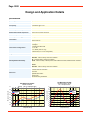
Tower Dryer Operations & Service
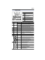
TABLE OF CONTENTS
DRYER OPERATION
SafetyFirst .......................................................................................................... 7
SafetyPrecautions .............................................................................................9
Installation Requirements ...............................................................................10
Dryer Control Panel........................................................................................... 11
Dryer Start Up.................................................................................................. 13
Dryer Shutdown................................................................................................ 17
Viewing Temperature/Moisture History........................................................... . 17
Viewing Burner/Fuel Train Status.................................................................... 17
Viewing Grain Flow Status............................................................................... 17
Setting the BPH Correction Factor................................................................... 17
TRI-POINT MOISTURE CONTROLLER
Main Screen...................................................................................................... 19
Set-Up of the Controller.................................................................................... 20
Operation Procedure......................................................................................... 21
How the Controller Works................................................................................ 22
Alarms............................................................................................................... 23
Access Drying History...................................................................................... 24
WARRANTY......................................................................................................... 191
MAINTENANCE
Pre-Seasonal Inspection And Service............................................................... 31
Seasonal Inspection And Service......................................................................32
End Of Season Service.....................................................................................32
Lubrication Table..............................................................................................33
Pre-Season/End of Season Checklist................................................................35
TROUBLE SHOOTING
Drying Issues.....................................................................................................39
Burner................................................................................................................39
General..............................................................................................................40
OIU (Screen) Messages.....................................................................................41
PARTS LIST
Commercial Tower Dryer Common Service Parts............................................46
Commercial Tower Dryer Sidewall Sheets.......................................................51
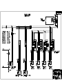
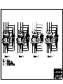
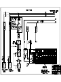
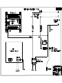
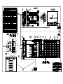
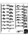
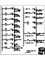
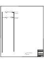
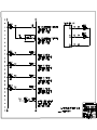
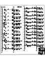
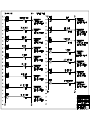
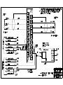
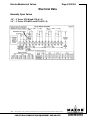
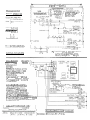
ELECTRICAL DIAGRAMS
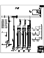
Tower Dryer Control Panel Wiring Diagrams...................................................53
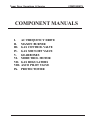
COMPONENT MANUALS
Allen-Bradley Variable Frequency Drive
Maxon "NP-LE" Burner
Maxon "CV" Gas Control Valve
Maxon "808" Gas Shut-Off Valve
Nord Gear Reduction Gear Unit
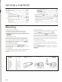
Sumitomo Cyclo-Drive Gear Unit
Honeywell Modutrol IV Motor Actuator
Invensys 121 Gas Regulator
ASCO Solenoid Valves
Protection Controls Protectofier Service Manual
DRYER
OPERATIONS
Tower Dryer Operations & Service
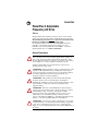
SAFETY FIRST
SAFETY GUIDELINES
This manual contains information that is important for you, the owner/operator, to know and
understand. This information relates to protecting personal safety and preventing
equipment problems. It is the responsibility of the owner/operator to inform anyone
operating or working in the area of this equipment of these safety guidlines.To help you
recognize this information, we use the symbols that are defined below.
Please read the manual and pay attention to these sections. Failure to read this manual
and it’s safety instructions is a misuse of the equipment and may lead to serious injury or death.
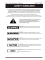
This is the safety alert symbol. It is used to alert you
to potential personal injury hazards. Obey all
safety messages that follow this symbol to avoid
possible injury or death.
DANGER indicates an imminently hazardous situation
which, if not avoided, will result in death or serious injury.
WARNING indicates a potentially hazardous situation
which, if not avoided, could result in death or serious injury.
CAUTION indicates a potentially hazardous situation which,
if not avoided, may result in minor or moderate injury.
CAUTION used without the safety alert symbol indicates a
potentially hazardous situation which, if not avoided, may
result in property damage.
NOTE indicates information about the equipment that you
should pay special attention to.
1
SAFETY FIRST
The GSI Group Inc.'s principle
concern is your safety and the
safety of others associated with
grain handling equipment. This
manual was written with that
thought in mind. We want to
keep you as a customer by
helping you understand
Tower Dryer Operations & Service
safe operating procedures, and
some of the problems that may
be encountered by the dryer
operator or other personnel.
As owner and/or operator, it is
your responsibility to know
what requirements, hazards and
precautions exist, and to inform
all personnel associated with
the equipment or who are in the
dryer area. Avoid any alterations to the equipment. Such
alterations may produce a very
dangerous situation, where
serious injury or death may
occur.
The GSI Group, Inc. recommends you contact
your local power company and have a representative
survey your dryer installation, so your wiring will be
compatible with their system and you will have adequate power supplied to your unit.
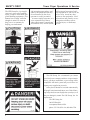
Safety decals should be read and understood by
all people in and around the dryer area. If the following safety decals are not displayed on your dryer, or if
they are damaged, contact The GSI Group, Inc. for
replacement:
The GSI Group, Inc.
1004 E. Illinois St.
Assumption, Illinois 62510
phone: 217-226-4421 • fax: 800-800-5329
2
Tower Dryer Operations & Service
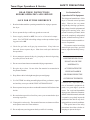
READ THESE INSTRUCTIONS
BEFORE OPERATION AND SERVICE
SAFETY PRECAUTIONS
Use Caution In The
Operation Of This Equipment
4. Check for gas leaks at all gas pipe connections. If any leaks are
detected, do not operate dryer. Shut down and repair before further operation.
The design and manufacture of this
dryer is directed toward operator
safety. However, the very nature
of a grain dryer having a gas burner,
high voltage electrical equipment and
high speed rotating parts, does
present a hazard to personnel, which
can not be completely safeguarded
against, without interfering with efficient operation and reasonable access to components.
Use extreme caution in working
around high speed fans, gas-fired
heaters, augers and auxiliary conveyors.
5. Never attempt to operate the dryer by jumping or otherwise bypassing
any safety devices on the unit.
KEEP THE DRYER CLEAN
SAVE FOR FUTURE REFERENCE
1. Read and understand the operating manual before trying to operate
the dryer.
2. Never operate the dryer while any guards are removed.
3. Power supply should be OFF for service of electrical components. Use CAUTION in checking voltage or other procedures requiring power to be ON.
DO NOT ALLOW FINE
6. Do not exceed maximum recommended drying temperatures.
7. Keep the dryer clean. Do not allow fine material to accumulate in
the plenum chamber.
8. Keep blower drive belts tight enough to prevent slippage.
MATERIAL TO
ACCUMULATE IN THE
PLENUM CHAMBER
OR SURROUNDING THE
OUTSIDE OF THE DRYER
9. Use CAUTION in working around high speed fans, gas burners, augers
and auxiliary conveyors which START AUTOMATICALLY.
10. Do not operate in any area where combustible material will be drawn into
the fan.
11. Be certain that capacities of auxiliary conveyors are matched to dryer
metering capacities.
12. Clean grain is easier to dry. Fine material increases resistance to airflow
and requires removal of extra moisture.
13. Do not adjust any moving part on the dryer while it is running.
Continued safe, dependable operation of automatic equipment depends, to a great degree, upon the
owner. For a safe and dependable
drying system, follow the recommendations within this manual, and make
it a practice to regularly inspect the
operation of the unit for any developing problems or unsafe conditions.
Take special note of the safety
precautions listed above before attempting to operate the dryer.
3
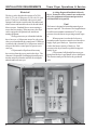
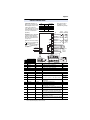
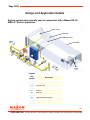
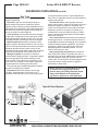
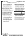
INSTALLATION REQUIREMENTS
Electrical
The dryer can be furnished to operate off of 240,
480, or 575 volt, 60 Hz power or 380 volt, 50 cycle
power. The dryer is furnished with a power panel
equipped with a main circuit breaker disconnect and
motor starters and branch breakers for the individual
blower motors. Standard blower motor starting is
across-the-line starting. When necessary, the dryer
can be equipped with optional soft-start motor
starting equipment.
No dry grain conveyor is furnished with the
dryer, however, a 10 hp motor starter for a dry grain
conveyor is furnished in the control panel. If the dryer
is ordered with a demand fill, a 10 hp motor starter is
also provided in the control panel to operate a wet
conveyor.
GSI personnel will perform all necessary
dryer wiring from the power panel to the dryer. The
customer is responsible for bringing electrical power
into the main circuit breaker and also for wiring the
unload (and load) conveyor.
Tower Dryer Operations & Service
A wiring diagram is furnished with each
dryer. Extensive safety controls are used on the
dryer for equipment and personnel protection
and should not be bypassed.
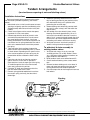
Fuel
The burner is designed to burn either natural gas or
propane vapor fuel. The volume of fuel supplied must
be sufficient to maintain a minimum of 7 to 10 psi
pressure when the burner is operating at rated capacity.
When propane is used as the fuel source,
external propane vaporizers must be used in order to
supply vapor gas to the dryer. Vaporizers must be
sized to the burner capacity of the dryer. Fuel
pressure to the dryer must be regulated to approximately 10 psi.
GSI personnel will plumb all necessary gas
piping from the dryer's gas shutoff valve to the burner.
The customer must provide fuel to the gas shutoff
valve.
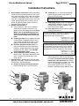
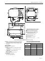
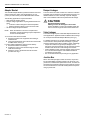
The electrical box on the GSI Tower Dryer.
4
Tower Dryer Operations & Service
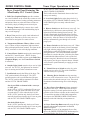
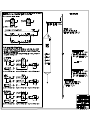
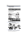
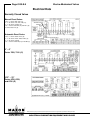
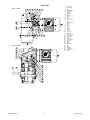
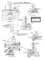
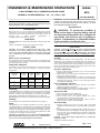
DRYER CONTROL PANEL
1
2
3
4
C
D
E
F
7
11
5
13
14
6
8
9
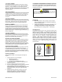
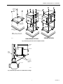
Figure 1:
10
12
The grain dryer control panel with full color touch screen control.
5
DRYER CONTROL PANEL
Dryer Control Panel Featuring The
Allen-Bradley PLC Control System
1. Full Color Graphical Display provides continuous visual feedback on the current dryer status as well
as a convenient means of setting operating parameters
and options. Most set points and status screens are
accessed by simply touching an on-screen object.
2. Message Center displays current dryer conditions and alarm messages with toubleshooting tips in
easy to read language.
3. Dryer View provides a quick visual indication of
primary dryer functions as well as easy access to
current burner and grain flow status screens.
4. Temperature/Moisture History Chart records
up to 32 hours of dryer temperature and/or moisture
data (with optional moisture control). The chart can be
easily "rewound" to view earlier drying conditions.
5. Control Power Switch energizes the control panel
and the PLC Control System. (NOTE: It takes
approximately 60 seconds to power up the Full Color
Graphical Display once the Control Power Switch
is turned on).
6. Outside Light Switch turns the dryer service light
on or off. On "AUTO", the light turns on when the
dryer is running and off when a shutdown occurs.
7. Load Switch controls the filling of the dryer. The
"ON" position initially fills the dryer. The "OFF"
position turns the conveyor off/shuts the slide gate.
The "AUTO" position enables automatic fill control
and the OUT OF GRAIN TIMER.
On dryers filled on demand with a conveyor
or slide gate:
In the "ON" or "AUTO" position the fill conveyor
turns on / slide gate opens when the dryer is low
on grain and off / closes when the dryer is full.
In the "AUTO" position only, the dryer will automatically shut down when the dryer is low on grain
and the OUT OF GRAIN TIMER expires.
On choke filled dryers:
In the "AUTO" position only, the dryer will automatically shut down when the dryer is low on grain
and the OUT OF GRAIN TIMER expires.
6
Tower Dryer Operations & Service
In the "ON" or "OFF" position the OUT OF
GRAIN TIMER IS DISABLED.
The LOAD switch is illuminated whenever the load
conveyor is running.
8. Low Grain Light flashes when the grain level is
low and the OUT OF GRAIN TIMER is running. The
LOW GRAIN light is on steady when the timer
expires.
9. Blowers Switch turns the blower(s) on or off. On
multifan dryers, the blowers start sequentially. The
lighted switch flashes during blower start-up. The
switch is illuminated when all of the blower airflow
switches close indicating that the blowers are operating correctly. After the closure of all of the airflow,
the dryer automatically goes through a 30 second
purge cycle.
10. Burner Switch turns the burner on or off. When
the switch is turned on, the burner pilot will automatically light, after the purging cycle is completed. The
lighted burner switch will flash during the 15 second
pilot ignition time. The switch illuminates when the
pilot flame is sensed at the pilot. After the pilot flame
is established the Maxon shut-off valves in the fuel
train are energized. Motorized valves will automatically open to provide gas to the main burner. Manual
valves must be opened manually to supply gas to the
main burner.
11. Unload Conveyor Switch turns the dry grain
unload conveyor on or off. The switch illuminates
when the conveyor is operating.
12. Metering Device Switch turns the metering
device on or off in forward or reverse. The device will
not run unless the unload conveyor is on. The switch
illuminates when the metering device is discharging
grain.
13. Dryer Power Start Button initiates automatic
operation of the dryer. When depressed, the dryer
begins the startup cycle and operates based on the
positions of the selector switches on the control panel.
To control the operation of individual components,
first depress the DRYER POWER START button,
then turn on the individual dryer components as
desired.
14. Dryer Power Stop Button manually stops all dryer
functions and automatic equipment in a controlled
shutdown sequence.
Important: In case of an automatic dryer shutdown, the DRYER POWER STOP button must be
depressed before the dryer can be restarted.
Tower Dryer Operations & Service
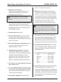
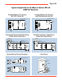
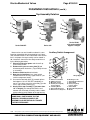
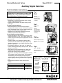
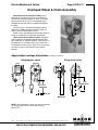
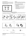
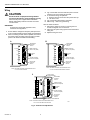
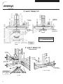
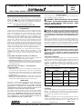
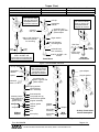
DRYER START UP
dryer. (ie. wet legs, conveyors, etc.)
1. Prepare dryer for start up
Perform preseason inspection and service as
outlined in the Maintenance Section before
attempting to operate the dryer.
The dryer must have all Pre-Season and
Post-Season maintenance to ensure reliable
operation
Make sure all discharge doors, grain exchanger
cleanout doors, heat section door, louvered
cooling section doors, etc. are closed. Make sure
that all personnel are clear of the dryer and any
grain handling machinery.
2. Open main gas valve to dryer.
3. Switch on main breaker to provide electrical
power to the dryer by placing the main circuit
breaker handle located on the dryer power panel
to the "ON" position.
4. Pull out both Emergency Stop Buttons located
on the side of the control and power box to
enable the main PLC circuit.
5.1 Switch on the control panel by turning the
CONTROL POWER selector switch to the
"ON" position. The switch will illuminate indicating that the control panel has power and is
operating correctly. After a short series of selfdiagnostic tests, the LCD display screen will
display a copyright message and a start button.
5.2 Press the on-screen Start button to enter the
dryer status screen.
6. Press the DRYER POWER "START" button
to activate the LOAD, BLOWERS, BURNER,
UNLOAD and METERING DEVICE selector
switches on the control panel.
7. Start auxiliary equipment needed for filling
8. Fill the dryer by turning the LOAD selector
switch to the "ON" position. On a demand fill
dryer, the wet conveyor will turn on / slide gate
will open and the dryer will start filling with grain.
Once the dryer is full, a horn will sound and the
wet conveyor will stop / slide gate will shut. Turn
the LOAD selector switch to the "AUTO"
position to silence the alarm and begin normal
The burner should be covered before filling
the dryer to prevent accumulation of foreign
material on the Ignitor, Flame Sensor, and Burner
Ports. Foreign material may interfere with burner
operation.
dryer operation. In the "AUTO" position, the
dryer automatically controls the conveyor / slide
gate and the OUT OF GRAIN TIMER is enabled, allowing automatic shutdown if the dryer
remains low on grain after a preset period of time.
9. Set drying / plenum temperature by touching
the P.L. Temp box on the LCD display. On the
pop-up keypad that is displayed, enter the new
drying temperature.
Recommended Drying Temperatures
Corn..............................180o to 210oF
Soybeans......................140o to 160oF
Wheat...........................140o to 160oF
Milo..............................160o to 180oF
Barley...........................140o to 160oF
Oats..............................140o to 160oF
10. Start the blower(s) by turning the BLOWERS
selector switch to the "ON" position. The
blower(s) will automatically start. On multiblower
units the PLC will automatically, start the blowers
sequentially. Once the blower(s) are up to speed
the airswitches will close and the blower switch
light will illuminate.
7
Tower Dryer Operations & Service
DRYER START UP
5.1
8
10
11
14
14
5.2
9
15
NOTE:
8
PRESS TO ENTER NEW TEMP.
OR UNLOAD RATE
6
Tower Dryer Operations & Service
11. Start the burner by turning the BURNER
selector switch to the "ON" position. The dryer
automatically goes through a 30 second purge
period once the blowers are started. The amount
of time remaining on the purge cycle will be
displayed on the LCD display screen. After the
purge period the burner pilot will automatically
light. Once the flame control circuit on the dryer
senses flame, the light in the BURNER selector
switch will illuminate. If the pilot fails to light in 15
seconds the burner will lock out and must be
restarted by turning the BURNER switch "OFF"
then back "ON".
12. Cock and open the Maxon valves. After the
pilot is ignited, the main burner can be lit by
cocking and opening the two Maxon gas shutoff
valves. These valves will automatically open on
dryers equipped with motorized Maxon Valves.
The main burner will light and the dryer's plenum
temperature will be automatically controlled by
the modulating motor and maintained at the
selected temperature.
12.1 Open firing valve (Canadian dryers only)
13. Let plenum come up to temperature and
begin drying. Depending upon ambient conditions, the dryer may take 10 minutes or more to
reach the drying temperature.
14. Start unload system. Before discharging grain
from the dryer, first make sure all dry legs and conveyors are operating ahead of the dryer. Turn the
UNLOAD CONVEYOR selector switch to the
The metering device will not run unless the unload conveyor is also running.
"ON" position to operate the dry grain conveyor
leading from the dryer. Turn the METERING DEVICE selector switch to the "FORWARD" position
to start discharging grain from the dryer.
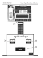
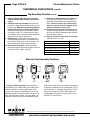
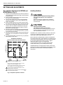
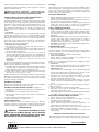
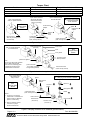
DRYER START UP
15. Set Unload Rate/Moisture Control Temperature manually. While operating the dryer in
manual mode, set the unload rate by touching the
U.L. Rate box on the LCD display. On the popup keypad, enter the new unload rate and press
return.
16. Check discharge moisture content after 10
minutes. Take five small samples from the discharge and mix before taking a moisture reading.
17. Switch over to Automatic Moisture Control.
When the discharge moisture content has stabilized at the desired amount for 20 to 30 minutes,
the dryer may be switched over to Automatic
Moisture Control.
17.1 Press the MOISTURE CONTROL button at
the bottom of the LCD screen.
17.2 On the Moisture Control Setup screen, set the
upper and lower limits by touching the corresponding box and using the pop-up keypad.
These values prevent the unload from moving too
fast or too slow should the incoming moisture be
significantly greater or less than anticipated.
17.3 Press the CONTROL MODE box to toggle
between Manual and Automatic moisture control.
Note that the current and target grain tempertures
are displayed next to the Temperature History
Chart.
If the discharge moisture content is consistently too high or too low, adjust the target grain
temperature as follows:
5oF increase = 1 moisture point decrease
5oF decrease = 1 moisture point increase
Allow 30 minutes between adjustments.
9
Tower Dryer Operations & Service
DRYER START UP
17.1
17.2
17.2
17.3
10
Tower Dryer Operations & Service
18. Shutdown dryer. The dryer will likely have to be
shutdown from time to time. The steps used to
shut it down will depend upon the duration of the
shutdown. If the dryer will be shutdown for 4
hours or less, follow the Short Shutdown procedure. For longer shutdowns, such as overnight,
follow the Extended Shutdown procedure
Short Shutdowns - Less than 4 hours
For short shutdown periods, the dryer can be
shutdown by pushing the DRYER POWER
STOP button. To restart the dryer, push the
DRYER POWER START button. The PLC will
restart the dryer automatically based on selector switch settings.
Extended Shutdowns - 4 hours or more
1. Shut off the burner. Turn the BURNER selector switch to the "OFF" position. All gas
valves will immediately close and the burner
will extinguish.
2. Cool down grain. PLC will continue to operate blowers to cool grain. To avoid overdried
grain upon restarting the dryer, continue to
move grain through the dryer during the cooling off period.
DRYER SHUTDOWN
8. Inspect the inside of the dryer after operation to insure against the possibility of hot spots
or fires.
Viewing Temperature/Moisture
History
Press the left and right arrows above the Temperature/Moisture History Chart to move backward and
forward through the graph.
Viewing Burner/Fuel Train Status
Press the Burner region in the Dryer View portion of
the LCD display to switch to the Fuel Train Status
screen. This screen displays the open/closed state of
all valves as well as the modulating valve control
value.
Viewing Grain Flow Status
Press the Unload region in the Dryer View portion
of the LCD display to switch to the Grain Flow
Status screen. This screen displays therunning status
of all controlled/interlocked equipment in the grain
flow path.
Modifying the Bushel Per Hour Factor
3. Shut off unload equipment. Turn METERING DEVICE and UNLOAD CONVEYOR
selector switches to "OFF" position.
4. Shut off blowers. Turn BLOWER selector
switch to "OFF" position.
5. Shut off control panel. Turn the CONTROL
POWER selector switch to the "OFF" position.
6. Turn off main circuit breaker located on
the power panel.
The bushel per hour reading given by the PLC is a
calculated value based on metering device speed.
Due to variations in grain test weight and unload
system settings, the correction factor may need to
be calibrated so that the calculated and actual grain
flow rates agree. The bushel per hour factor is
normally set at 1.0. If, for example, the actual grain
flow rate is 5 percent higher than displayed, change
the bushel per hour factor to 1.05. To adjust the
correction factor, press the DRYER SETUP button,
then the BUSHEL COUNTER button. Press the
CORRECTION FACTOR box to adjust the value.
7. Close main gas valve to the dryer.
11
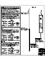
TRI-POINT MOISTURE CONTROLLER Tower Dryer Operations & Service
Optional Tri-Point
Moisture
Controller
Operation Manual
12
Tower Dryer Operations & Service TRI-POINT MOISTURE CONTROLLER
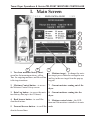
I. Main Screen
9
8
7
6
5
1
2
3
4
1. Two-hour moisture history chart green line for incoming moisture; yellow
line for outgoing moisture; and the red line
is the target moisture.
6. Moisture target - To change the moisture target, press within the rectangular area
and key in the new target from the pop-up
keypad.
2. Moisture Control button - to access
the Moisture Control Set-up screen.
7. Current moisture coming out of the
dryer.
3. Data Log button - to access the moisture history data (up to last 30 hours).
8. Current moisture coming into the
dryer.
4. Back browse button - to scroll the
chart back in time.
9. Moisture control status - the LED
turns on if the moisture controller is in auto
5. Forward browse button - to scroll the mode
chart in forward time
13
TRI-POINT MOISTURE CONTROLLER Tower Dryer Operations & Service
II. Set-Up of the Controller
*Press the “MOIST CONTROL” button from the main screen to access the moisture set-up
screen:
1
6
2
5
1.
Unload upper limit - the maximum
unloading rate (%) in which dryer can be
run without plugging any unloading conveyors.
2.
Current column grain temperature - measured from the RTD sensor at
the end of the drying section (it is not the
temperatureof the grain coming out of the
dryer).
3.
Unload lower limit - the minimum
unloading speed that can maintain the sampling box of the dry sensor full of grain. It
is essential to have the sensor fully covered
14
3
4
by grain to get an accurate reading of
the grain moisture.
4.
Calibration button - to access
sensor calibration screen (see Section III,
Step 3).
5.
Control Mode button - toggle the
control mode between MANUAL and
AUTO by pressing the button.
6.
Moisture Control Diagnosis
button - to access the diagnostic screen for
factory trouble shooting.
Tower Dryer Operations & Service TRI-POINT MOISTURE CONTROLLER
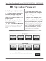
III. Operation Procedure
1. Start the dryer; set the dryer unload at a
desired speed from the dryer control panel.
2. Let the dryer run under manual mode
for warming up until the column grain
temperature has stabilized and the moisture
coming out of the dryer is within ± 2% of
the target moisture.
3. During the start-up period, calibrate
both the wet and dry sensors against a
bench meter as follows:
a) Press “SENSOR CALIBRATION”
button from the moisture control set-up
screen to open the sensor calibration
screen.
b) Take grain samples from the dryer,
measure the moisture with a bench meter
and then compare to the sensor reading
during the sampling period.
Change the sensor offset if the sensor
reading does not match the bench measurement. For example, if the offset was 1.0%,
and the sensor reading is 0.5% lower than
the bench meter, then change the offset to
1.5% to match the sensor to the bench
meter. Likewise, if the sensor reading is
higher than the bench meter, the offset
should be decreased accordingly.
15
TRI-POINT MOISTURE CONTROLLER Tower Dryer Operations & Service
The sensor should be calibrated 2-3 times a
day. At the same time check and clean the sensor
and sensor sampling box to make sure that there is
no debris blocking the grain flow around the
sensor.
4. Check or change the target moisture
from the main screen.
5. Press “MOIST CONTROL” to access the moisture control set-up screen.
Check upper/lower unloading limits and
change them if needed.
6. Press the “CONTROL MODE”
button from the moisture control set-up
screen and set the mode to AUTO. The
moisture controller will start adjusting the
unload rate between the upper and lower
limits of the unload speed to maintain the
moisture coming out of the dryer.
IV. How the Controller Works
The controller continuously monitors the
slows down the dryer gradually so that the
moisture coming in and out of the dryer,
grain currently in the dryer will not be
and the column grain temperature at the end overdried too much.
of the drying section. The control action is
mainly based on the dry sensor at the outlet In the first pass after the dryer started, the
of the dryer. If the moisture coming out of controller does not have enough informathe dryer is not right at the target, the controller will speed up or slow down the
unload device accordingly. The wet sensor
tion of the grain in the dryer. It controls the
dryer by using the manual speed setting as a
starting point. In other words, the manual
and the column grain temperature sensor are speed setting is most responsible for the
intended to detect moisture spikes coming first pass of drying. Therefore, set the
into the dryer so that the moisture controller manual unloading speed as close as it
can react ahead of time. For example, if the should be for the grain currently in the dryer
before switching to AUTO control mode.
wet sensor detects a jump of moisture
coming into the dryer, the controller will
start slowing down the unload speed right
away. However, the controller does not act
to the full scale immediately. Instead, it
16
The manual speed setting does not have to
be adjusted after the controller is switched
into AUTO mode.
Tower Dryer Operations & Service TRI-POINT MOISTURE CONTROLLER
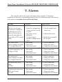
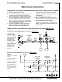
V. Alarms
The controller checks the sensors and control status regularly. If abnormal
conditions are detected, a corresponding alarm will go off, an alarm message will come up
on the main screen and the dryer will be shut down.
ALARM
CAUSES
SOLUTION
Moisture out of range the moisture coming out
of the dryer was 2.5%
above or below the setpoint for more than one
hour under AUTO control
mode
• Sensor box plugged and
sensor was not covered
by grain
• Dry sensor out of
calibration
• Too big swing of
moisture coming into the
dryer
• Clear the sampler and
sensor box
Dry sensor error sensor reading is less than
6% or higher than 40%
• Bad wiring
• Bad sensor
• Bad circuit board
• Check connection
• Change the sensor
• Change the circuit board
Dry grain temperature out
of range (0-300F)
• Bad wiring
• Bad sensor
• Bad circuit board
• Check connection
• Change the sensor
• Change the circuit board
Wet sensor error sensor readng is less than
6% or higher than 40%
• Bad wiring
• Bad sensor
• Bad circuit board
• Check connection
• Change the sensor
• Change the circuit board
Wet grain temp. out of
range
(0-300F)
• Bad wiring
• Bad sensor
• Bad circuit board
• Check connection
• Change the sensor
• Change the circuit board
Column grain temperature
RTD out of range
(0-300F)
• Bad wiring
• Bad sensor
• Bad circuit board
• Check connection
• Change the sensor
• Change the circuit board
• Calibrate the sensor
• Run the dryer manually
for one pass
17
TRI-POINT MOISTURE CONTROLLER Tower Dryer Operations & Service
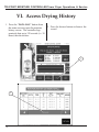
VI. Access Drying History
1. Press the “DATA LOG” button from
the main screen to open the moisture
history screen. The controller logs
quarterly data up to 120 records (i.e. 30
hours) into the archive.
2. Press the browse buttons to browse the
record.
1
2
18
Tower Dryer Operations & Service
NOTES
______________________________________________________________________________________________________
_______________________________________________________________________________________________________
______________________________________________________________________________________________________
__________________________________________________________________________________________________________
___________________________________________________________________________________________________________
__________________________________________________________________________________________________________
________________________________________________________________________________________________________
__________________________________________________________________________________________________________
_________________________________________________________________________________________________________
_______________________________________________________________________________________________________
_________________________________________________________________________________________________________
_______________________________________________________________________________________________________
__________________________________________________________________________________________________
___________________________________________________________________________________________________
_____________________________________________________________________________________________________
____________________________________________________________________________________________________
________________________________________________________________________________________________________
_______________________________________________________________________________________________________
________________________________________________________________________________________________________
_________________________________________________________________________________________________________
________________________________________________________________________________________________________
______________________________________________________________________________________________________
________________________________________________________________________________________________________
____________________________________________________________________________________________________
_______________________________________________________________________________________________________
______________________________________________________________________________________________________
___________________________________________________________________________________________________________
19
NOTES
Tower Dryer Operations & Service
______________________________________________________________________________________________________
_______________________________________________________________________________________________________
______________________________________________________________________________________________________
__________________________________________________________________________________________________________
___________________________________________________________________________________________________________
__________________________________________________________________________________________________________
________________________________________________________________________________________________________
__________________________________________________________________________________________________________
_________________________________________________________________________________________________________
_______________________________________________________________________________________________________
_________________________________________________________________________________________________________
_______________________________________________________________________________________________________
__________________________________________________________________________________________________
___________________________________________________________________________________________________
_____________________________________________________________________________________________________
____________________________________________________________________________________________________
________________________________________________________________________________________________________
_______________________________________________________________________________________________________
________________________________________________________________________________________________________
_________________________________________________________________________________________________________
________________________________________________________________________________________________________
______________________________________________________________________________________________________
________________________________________________________________________________________________________
____________________________________________________________________________________________________
_______________________________________________________________________________________________________
______________________________________________________________________________________________________
20
Tower Dryer Operations & Service
NOTES
______________________________________________________________________________________________________
_______________________________________________________________________________________________________
______________________________________________________________________________________________________
__________________________________________________________________________________________________________
___________________________________________________________________________________________________________
__________________________________________________________________________________________________________
________________________________________________________________________________________________________
__________________________________________________________________________________________________________
_________________________________________________________________________________________________________
_______________________________________________________________________________________________________
_________________________________________________________________________________________________________
_______________________________________________________________________________________________________
__________________________________________________________________________________________________
___________________________________________________________________________________________________
_____________________________________________________________________________________________________
____________________________________________________________________________________________________
________________________________________________________________________________________________________
_______________________________________________________________________________________________________
________________________________________________________________________________________________________
_________________________________________________________________________________________________________
________________________________________________________________________________________________________
______________________________________________________________________________________________________
________________________________________________________________________________________________________
____________________________________________________________________________________________________
_______________________________________________________________________________________________________
______________________________________________________________________________________________________
___________________________________________________________________________________________________________
21
NOTES
Tower Dryer Operations & Service
______________________________________________________________________________________________________
_______________________________________________________________________________________________________
______________________________________________________________________________________________________
__________________________________________________________________________________________________________
___________________________________________________________________________________________________________
__________________________________________________________________________________________________________
________________________________________________________________________________________________________
__________________________________________________________________________________________________________
_________________________________________________________________________________________________________
_______________________________________________________________________________________________________
_________________________________________________________________________________________________________
_______________________________________________________________________________________________________
__________________________________________________________________________________________________
___________________________________________________________________________________________________
_____________________________________________________________________________________________________
____________________________________________________________________________________________________
________________________________________________________________________________________________________
_______________________________________________________________________________________________________
________________________________________________________________________________________________________
_________________________________________________________________________________________________________
________________________________________________________________________________________________________
______________________________________________________________________________________________________
________________________________________________________________________________________________________
____________________________________________________________________________________________________
_______________________________________________________________________________________________________
______________________________________________________________________________________________________
20
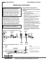
MAINTENANCE
MAINTENANCE
Tower Dryer Operations & Service
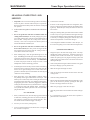
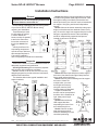
PRE-SEASONAL INSPECTION AND
SERVICE
The dryer is made of weather resistant material, and is
designed to require minimum service. However, each
season we recommend the following items be checked
before the unit is used, and any damaged or questionable parts replaced. These checks will help eliminate
possible failures, and assure dependable operation of
the equipment.
1. Shut off electrical power. Open power box and
control box, and inspect for moisture, rodent damage or accumulated foreign material present. Inspect and tighten any loose terminal connections.
Replace any damaged or deteriorated wiring.
2. Lubricate the blowers, motors, and metering system as outlined in the Lubrication Table below.
3. Check blower belts for proper tension.
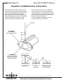
4. Inspect and clean the burner. Visually check that
no holes in the stainless steel air mixing plates are
plugged. If burner ports are plugged, clear them
with a piece of wire or a drill bit. After a period of
several years, it may become necessary to drill
out the burner ports to clear away accumulated
rust. Use a #43 drill bit to return burner ports to
their original diameter. (See burner drilling procedure in the Maxon Burner area of the COMPONENT MANUALS section of this book.)
(NOTE: Pre-2002 model dryers require a #47
drill bit.)
5. Check electrical connections at both the flame rod
and spark plug. Clean spark ignitor and flame
rod. Replace if necessary.
6. Check drain valve on gas train to insure that there
is no water in the gas train. Valve should always
be open when the dryer is not being used. Insure
that drain valve is closed prior to dryer operation.
7. Lubricate linkage on gas modulating valve.
24
8. On Zimmerman Dryers equipped with the
Accutrol sweep unload metering system, check
the discharge area to insure that the area is cleaned
of stalks and old grain. Inspect the sweeps for
excessive wear.
9. On GSI Dryers equipped with the hoppered
metering system, check the hopper area and the
area around the metering drum to insure that they
are cleaned of stalks and old grain. Check the
edges of the metering drum for excessive wear.
10. Important!! The covers to the discharge
sections on both the Zimmerman and GSI Tower
dryers must be in place and clamped down at all
times when the dryer is in operation. If the cover
is off during operation, the vacuum created by the
blowers will suck foreign matter from the
discharge area and deposit it in the heat section of
the dryer plugging the inside screens of the dryer
also creating a fire hazzard.
SEE PRE-SEASON CHECKLIST AT
THE END OF THIS SECTION
MAINTENANCE
Tower Dryer Operations & Service
SEASONAL INSPECTION AND
SERVICE
1.
2.
3.
4.
5.
6.
7.
Important! The covers to the metering system access door(s) 4.
must be in place at all times when the dryer is in operation.
Before turning blowers always make sure this door is clamped 5.
into position.
Follow lubrication guides as outlined in the Lubrication
Table.
6.
Do not let grain fines and dust accumulate inside the
cooling section of the dryer. Bi-weekly if drying most products or daily if drying milo, clean the cooling chamber floor of
fines and dust. Sweep down the cooling section sheets if
necessary. Fines can be swept into the unload systems on
7.
both the Zimmerman and GSI dryers.
Do not let grain fines and dust accumulate inside the
heat section of the dryer. Daily check the hopper divider
that separates the heat section from the cooling section to
insure that it remains clean and open.
1.
When cleaning dryer, check the grain discharge area on the
dryer. On GSI hopper bottom dryers check around the metering drum to insure that grain is flowing freely from each column and that there is no trash build-up. On Zimmerman
Accutrol sweep dryers check the sweeps for trash or stalk
buildups that could be obstructing grain flow.
2.
If undried grain is left in the dryer for more than a week during
the drying season, inspect the plenum roof to make sure that 3.
there is no wet grain sticking to the roof that could restrict
grain flow. When the dryer is restarted make sure that all grain 4.
columns are evenly unloading.
When drying dirty corn in high humidity conditions, sludge
5.
may build up in the upper outside sheets of the dryer. This
build up can be removed by either washing the sheets down
6.
with a high pressure water hose, or by shutting incoming grain,
dropping the grain level to below the plugged area, and then
running the fans and burner to dry the affected area. Tapping
or sweeping the sheets will dislodge debris. Attempting to
7.
sweep off the sheet build-up while it is still wet will usually
plug the sheet more.
8.
IN CASE OF FIRE
1.
When you first detect a fire, the entire drying operation should
be shut down, including grain flow into and out of the dryer.
The emergency controls may have already done this. Also,
shut off the electrical and fuel supply to the dryer.
2.
Do not try to cool a fire by running fan(s).
3.
Never run grain from the dryer into the elevator or storage if a
fire is known or suspected.
26
9.
Locate the area of the fire.
If the fire can be extinguished with a fire extinguisher, water
hose or by removing the burning material, this should be done
right away. Watch the dryer closely for another fire after one
has occurred.
Emergency discharge slide gates at the bottom of each column
as well as easy access gates located near the hopper discharge
area permit fast dumping of each individual grain column. If it
is necessary to emergency dump grain from the dryer, wait
until the fire department is onsite before doing so.
A fire extinguisher should be located at or near the dryer, if a
fire seems to be getting out of control call the fire department.
END OF SEASON SERVICE
Empty the dryer at the end of the drying season. The dryer
should not be used for grain storage. Grain left in there for an
extended period of time can become wet, swell and spoil.
Chunks of spoiled grain can plug the metering system and
swelled grain places undue stress on the interior and exterior
sheeting of the dryer.
Clean out the plenum roof grain cushion and remove any grain
that may be hanging up on the plenum roof.
Make sure the grain exchangers are clean.
Clean out the hopper that divides the heat section from the
cooling section.
Clean the cooling chamber floor.
Remove all grain and trash from the metering drum floor. This
grain can be raked out by hand by opening the slide gates
located in the hopper bottom of the dryer.
Make sure gas supply is shut off to the dryer.
Open the gas train drain valve located on the bottom of the gas
train.
It is a good practice to cover the burner with a tarpaulin or
plastic to insure a clean burner.
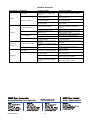
MAINTENANCE
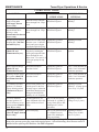
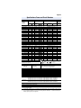
LOCATION
Tower Dryer Operations & Service
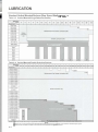
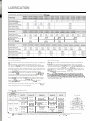
LUBRICATION TABLE
INSTRUCTIONS
TYPE OF
LUBRICATION
LUBRICATION
INTERVAL
Metering drum drive
shaft bearing (On
GSI hopper bottom
dryers only).
Accutrol (sweep unload)
top and bottom drive
bearings. (On
Zimmerman flat bottom
dryers only).
Lubricate slowly until lube
shows through seal. Wipe
clean.
High quality; grade #2
lithium based grease.
Beginning of season
(annually).
Lubricate slowly until lube
shows through seal. Wipe
clean.
High quality; grade #2
lithium based grease.
Beginning of season
(annually).
Accutrol (sweep unload)
coupling hub. (On Zimmerman Dryers).
Remove the two lube plugs High quality; grade #2
from the cover. Lubricate lithium based grease.
slowly until grease begins
seeping through relief plug.
High quality, grade #2
Lubricate bottom bearing
lithium based grease.
plug slowly counting the
grease gun pump until lube
shows through the seal.
Wipe clean. Use same # of
grease gun pumps for top
bearing.
Beginning of season
(annually).
Blower motor bearings
(Both GSI and
Zimmerman Dryers)
See motor lubrication
procedure below 1
High quality, grade #2
lithium based grease
Every 2 years (Normal operation, ever 8-10 months
continuous operation).
Metering variable speed
drive motor (Both GSI
and Zimmerman Dry
ers)
See motor lubrication
procedure below 1
High quality, grade #2
lithium based grease
Every 2 years (Normal operation, ever 8-10 months
continuous operation).
12’ Diameter Accutrol
gearbox (12’ diameter
sweep unload gearbox)
(Zimmerman Dryers
only)
Grease filled gearbox. Re- High quality, grade #2
plenish grease to the first
lithium based grease
1st stage (upper) reduction
mechanism through grease
fitting provided (typically
quantity= 0.3 oz. of grease
18’ & 24’ Diameter
Accutrol gearbox (18’
and 24’ diameter sweep
unload gearbox Zimmerman Dryers only).
Oil filled gearbox w/ oil
pump. Maintain oil level to
upper red line on oil level
gauge.
Blower shaft bearings.
(Both GSI and
Zimmerman Dryers).
Metering drum gearbox. Fill to check plug.
(On GSI hopper bottom
dryers only)
Every 4 weeks of dryer
operation.
Beginning of season
(annually). (Change grease
in box every 3-5 years)
ISO VG 100 to 150 minBeginning of season.
eral-based oil. AGMA Vi- (Change every 2 years).
scosity Grade 3EP to 4EP.
(Mobilgear 627, 629 or
equivalent).
ISO VG 220 mineral-based Beginning of season.
oil. AGMA Viscos-ity
(Change every 10,000
Grade 5EP. (Mobilgear
hours or 2 years).
630 or equivalent).
Lubrication of motors - Operate motor for 20 minutes. Clean grease fitting. Remove grease relief plug and
using a low pressure grease gun, pump in the required grease. After relubricating, allow motor to run for 10
minutes before replacing relief hardware. Do NOT overgrease!
1
26
MAINTENANCE
26
Tower Dryer Operations & Service
MAINTENANCE
Tower Dryer Operations & Service
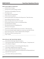
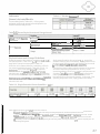
PRE-SEASON SERVICE CHECKLIST
_____ Lubricate blower bearings.
_____ Lubricate blower motor bearings, if needed.
_____ Check blower belts and adjust if necessary.
_____ Clean burner ports.
_____ Inspect flame rod and spark ignitor.
_____ Check oil levels in gearboxes.
_____ Inspect divider hopper between heat and cooling section. Clean if necessary.
_____ Inspect Bindicator grain level switches.
_____ Inspect metering system access door cover seals.
_____ Lube metering system access door cover hold down latches.
_____ Lube Modutrol motor linkage.
_____ Check butterfly operation in modulating valve.
_____ Check gas pressure gauges.
_____ Check interior of Maxon shutoff valves for corrosion. Clean if necessary.
_____ Clean control and power panels, tighten loose connections, and check for leaks.
_____ Inspect metering systems. Clean accumulated stalks and old grain.
_____ Start up dryer and check operating controls.
_____ Other: Itemize____________________________________________________
END OF SEASON SHUT-DOWN PROCEDURE
______ Start unload and and empty all grain from dryers.
______ Clean out grain cushion (on plenum roof under fill spout). Clean plenum roof.
______ Clean off grain exchangers.
______ Clean out divider hopper, between heating and cooling section.
______ Clean inside cooling sheets and cooling floor.
______ Remove all grain and trash from unload section of dryer.
______ Open emergency grain discharge doors (and drain doors in Zimmerman dryers).
______ Open drain valve in gas train.
______ Cover burner with a tarp or plastic sheeting.
28
TROUBLE
SHOOTING
TROUBLESHOOTING
Tower Dryer Operations & Service
The GSI & Zimmerman Tower dryers are designed to be self diagnosing. Most electrical or operating problems are
displayed on the screen of the operator interface and the problem area is graphically high lighted. Always insure that either
240 or 480 volt 3 phase power is being provided to the dryer. All motor starters coils and the burner circuitry operate at 120v
AC. All of the safety circuit on the dryer operates at 24v DC.
Listed below are potential trouble shooting issues associated with the dryer and possible solutions to the problems.
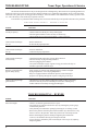
TROUBLESHOOTING – DRYING ISSUES
Problem
What to do
Low dryer capacity.
- Check to make sure the dryer is always full of grain.
- Check all grain columns to make sure they are all moving.
- Check outside dryer screen for dirt build up. Clean if necessary.
Grain moisture discharges
too wet.
- Reduce unload rate.
- Or increase drying temperature.
Grain moisture discharges
too dry.
- Increase unload rate.
- Or decrease drying temperature.
Grain moisture discharges
inconsistently.
- Check that plenum temperature is being held consistent.
- Check for widely varying incoming moistures.
- Check for plugged grain columns.
- Verify that an adequate supply of grain is being provided to the dryer to
maintain a grain seal within the dryer.
Burnt or scorched kernels
appear during drying.
- Some varieties of grain or frost damaged grain are sensitive to higher
drying temperatures. Lower drying temperatures.
- If dryer is equipped with an external LP vaporizer, insure that liquid
propane is not passing through the vaporizer and going to the dryer.
Grain not moving through
grain columns.
- Check the dryer for fines build up within the column. Empty if necessary.
- Do not leave the dryer full for extended periods of time or during rainy
weather without occasionally moving grain through it.
TROUBLESHOOTING – BURNER
Problem
What to do
Pilot will not light.
- Check to see that the gas shutoff valve is open.
- Verify that gas is being provided to the dryer by checking the presure gauge
located in the pilot line.
- Verify that the pilot solenoid is opening by listening for a “clicking” sound.
- Remove the pilot line from the pilot solenoid with the dryer turned off to verify
that no water is in the pilot line. Blow the pilot line out with compressed air.
- Before reattaching the pilot line attempt to light the pilot with the line
removed. Gas should be flowing from the pilot solenoid.
- If gas is flowing, reattach the pilot line and adjust of flow of gas by adjusting
the pilot regulator.
30
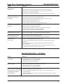
Tower Dryer Operations & Service
Problem
Pilot will not light.
(Continued)
TROUBLESHOOTING
What to do
- If pilot still doesn’t light, check pilot area on burner. Clean if necessary.
- If pilot area is hot indicating that the pilot was lighting, replace flame rod.
- If pilot area is cold, replace spark plug.
- If pilot still doesn’t light, check the Protectofier components in the control box.
Pilot lights but main burner
will not light
- Check for water in gas train by opening drain valve.
- Maxon valve should offer some resistance when opening. If it doesn’t,
check latching solenoid inside Maxon valve.
- Check for broken or bent butterfly valve.
- Check to make sure burner ports around the pilot are clean.
Dryer will not reach operating
temperature.
- Increase gas pressure on main gas regulator.
- Make sure dryer is completely full of grain.
- Gas ports on burner need to be drilled. Clean by using a #43 drill bit.
- Check to make sure butterfly valve is fully opening.
- Check for water in gas train by opening drain valve.
Plenum temperature fluctuates.
- Gas pressure is to high. Lower gas pressure on main gas regulator.
Dryer loses flame at regular
intervals while running.
- Loose or dirty flame rod. Clean and/or tighten.
- Defective Protectofier SS3CP transformer in control box. Replace.
Modulating Valve
does not open.
- Check to see that Maxon shutoff valves are open.
- Check to see that the plenum setpoint temperature is higher than the ambient
temperature.
- Check to see that 120VAC is being provided to the black and white wires in
the modutrol motor.
- Check the operation of the modutrol motor be momentary jumping the “F” and
“-“ terminals in the motor to see if the motor will open.
TROUBLESHOOTING – GENERAL
Problem
Control power switch
will not light.
What to do
- Check to see that main circuit breaker in power box is on.
- Check fuses “F1”, “F2”, “F3” in power box.
- Check circuit breaker “CB-04” in power box.
- Check MicroLogix PLC in control box.
OIU fails to light.
- Check to see that main circuit breaker in power box is on.
- Check fuses “F1”, “F2”, “F3” in power box.
- Check circuit breaker “CB-04” in power box.
Dryer shuts down, red light lights - Check for possible fire in heat section of dryer.
and horn sounds, display shows: - Make sure the plenum high limit control is set at least 30° above the desired
“OVERHEAT AT PLENUM”
drying temperature.
“POSSIBLE FIRE”
- Check for a malfunctioning gas train component that could be causing excessive
plenum temperatures.
31
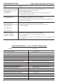
TROUBLESHOOTING
Tower Dryer Operations & Service
Problem
What to do
Dryer shuts down, red light lights
and horn sounds, display shows:
“OVERHEAT AT _________”
“POSSIBLE FIRE”
- Check for possible fire in dryer at location indicated in message.
- Check for a plugged or slow moving grain column.
- Check for a plugged grain turner.
- Check to insure that the dryer is full of grain and is continually being kept full.
- Check for a defective high limit sensor.
OIU displays message:
“UNLOAD DRIVE FAULT”
- Indicates that the metering system inverter drive has tripped.
- Check for plugged metering drum or Accutrol metering system.
- Reset drive by turning off the main circuit breaker for 15 seconds, or by pressing the
“STOP” button on the inverter.
OIU displays message:
- Indicates that any overload has occurred in the item indicated.
“CONTACT FAILED TO CLOSE” - Reset the overload of the starter indicated in the power panel and fix the
“DRY CONVEYOR”
overloaded conditions.
-or“WET CONVEYOR”
-orany auxiliary starter
OIU displays message:
“OVERLOAD TRIPPED”
“BLOWER __ STARTER”
- Indicates that overload has occurred in the blower indicated.
- Reset the overload of the starter of the blower indicated and fix the
overload conditions.
- Blower overload can be caused by overly tightened blower belts or inadequately greased
blower bearings.
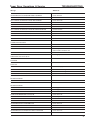
TROUBLESHOOTING – OIU (SCREEN) MESSAGES
Message
What to do
LOST COMM. TO MICRO
OVERHEAT AT TOP LEFT POSSIBLE FIRE!!!
Cycle the power
Check overheat condition and Term. 101
OVERHEAT AT TOP RIGHT POSSIBLE FIRE!!!
OVERHEAT AT MID. LEFT POSSIBLE FIRE!!!
Check overheat condition and Term. 102
Check overheat condition and Term. 103
OVERHEAT AT MID. RIGHT POSSIBLE FIRE!!!
OVERHEAT AT LOWER LEFT POSSIBLE FIRE!!!
Check overheat condition and Term. 104
Check overheat condition and Term. 105
OVERHEAT AT LOWER RIGHT POSSIBLE FIRE!!!
OVERHEAT AT INSIDE LEFT POSSIBLE FIRE!!!
Check overheat condition and Term. 106
Check overheat condition and Term. 107
OVERHEAT AT INSIDE RIGHT POSSIBLE FIRE!!!
OVERHEAT AT PLENUM POSSIBLE FIRE!!!
Check overheat condition and Term. 108
Check overheat condition and Term. 109
OVERLOAD TRIPPED TRI-STARTER
OVERLOAD TRIPPED BLOWER 1 STARTER
Check Term. 300
Check Term. 301
OVERLOAD TRIPPED BLOWER 2 STARTER
OVERLOAD TRIPPED BLOWER 3 STARTER
Check Term. 302
Check Term. 303
OVERLOAD TRIPPED BLOWER 4 STARTER
AUXILIARY STUCK CLOSED TRI-STARTER
Check Term. 304
Check Term. 200
AUXILIARY STUCK CLOSED BLOWER 1 STARTER
AUXILIARY STUCK CLOSED BLOWER 2 STARTER
Check Term. 201
Check Term. 202
32
Tower Dryer Operations & Service
TROUBLESHOOTING
Message
What to do
AUXILIARY STUCK CLOSED BLOWER 3 STARTER
Check Term 203
AUXILIARY STUCK CLOSED BLOWER 4 STARTER
AUX. CONTACT FAILED TO CLOSE TRI-STARTER
Check Term. 204
Check Term. 200
AUX. CONTACT FAILED TO CLOSE BLOWER 1 STARTER
AUX. CONTACT FAILED TO CLOSE BLOWER 2 STARTER
Check Term. 201
Check Term. 202
AUX. CONTACT FAILED TO CLOSE BLOWER 3 STARTER
AUX. CONTACT FAILED TO CLOSE BLOWER 4 STARTER
Check Term. 203
Check Term. 204
SWITCH OPEN AIR PRESSURE SWITCH 1
SWITCH OPEN AIR PRESSURE SWITCH 2
Check Term. 205
Check Term. 206
SWITCH OPEN AIR PRESSURE SWITCH 3
SWITCH OPEN AIR PRESSURE SWITCH 4
SWITCH OPEN AIR PRESSURE SWITCH OF
COMBUSTION BLOWER
LOST FLAME
Check Term. 207
Check Term. 306
Check Term. 115
SWITCH STUCK CLOSED MAXON VALVE
FLAME DETECTED WHILE BURNER IS OFF
Check Term. 113
Check if pilot or Maxon valves stuck open and check
flame rod, BCU and Term. 114
Check Term. 111
Check gas pressure and Term. 110
HI. GAS PRESSURE SWITCH OPEN
LOW GAS PRESSURE SWITCH OPEN MAKE
SURE MAIN GAS VALVE IS ON
HI. GAS PRESSURE SWITCH OPEN GAS PRESSURE
TOO HIGH
LOW GAS PRESSURE SWITCH OPEN GAS PRESSURE
TOO LOW
Check BCU and Term. 114
Check Term. 111
Check Term. 110
MAXON VALVES NOT TURN ON
PL. TEMPERATUR RTD CIRCUIT OPEN OR SHORTED
Reset and try again
Check the RTD wiring
GRAIN TEMPERATUR RTD CIRCUIT OPEN OR SHORTED
AUXILIARY STUCK CLOSED OIL PUMP STARTER
Check the RTD wiring
Check Term. 307
AUXILIARY STUCK CLOSED COMBUSTION
BLOWER STARTER
Check Term. 308
AUX. CONTACT FAILED TO CLOSE OIL PUMP STARTER
AUX. CONTACT FAILED TO CLOSE COMBUSTION
Check Term. 307
Check Term. 308
BLOWER STARTER
PLUG SWITCH OPEN DRY PATH PLUGGED
Clear dry path and check Term. 309
PLUG SWITCH OPEN HOPPER PLUGGED
UNLOAD DRIVE FAULT
Clear hopper and check Term. 310
Check the drive and Term. 208
OVERLOAD TRIPPED DRY CONVEYOR
PLUG SWITCH OPEN WET PATH PLUGGED
Check Term. 305
Clear wet path and check Term. 311
AUXILIARY STUCK CLOSED DRY CONVEYOR
AUXILIARY STUCK CLOSEDAUX. DRY CONVEYOR
Check Term. 209
Check Term. 210
AUXILIARY STUCK CLOSED DRY LEG
AUXILIARY STUCK CLOSED TOP DRY CONVEYOR
Check Term. 211
Check Term. 212
UNLOAD MONITOR PROXIMITY SWITCH OPEN
AUXILIARY STUCK CLOSED AUX. WET CONVEYOR
Check the unload device and Term. 313
Check Term. 215
AUXILIARY STUCK CLOSED WET LEG
Check Term. 214
33
TROUBLESHOOTING
Tower Dryer Operations & Service
Message
What to do
AUXILIARY STUCK CLOSED TOP WET CONVEYOR
Check Term. 213
CONTACT FAILED TO CLOSE DRY CONVEYOR
CONTACT FAILED TO CLOSE AUX. DRY CONVEYOR
Check Term. 209
Check Term. 210
CONTACT FAILED TO CLOSE DRY LEG
CONTACT FAILED TO CLOSE TOP DRY CONVEYOR
Check Term. 211
Check Term. 212
CONTACT FAILED TO CLOSE AUX. WET CONVEYOR
CONTACT FAILED TO CLOSE WET LEG
Check Term. 215
Check Term. 214
CONTACT FAILED TO CLOSE TOP WET CONVEYOR
BINDICATOR ERROR UBS closed while LBS still open
Check Term. 213
Check Term. 314 & 315
SHUT DOWN OUT OF GRAIN Occurred at ——
DRY SENSOR ERROR MOISTURE SIGNAL OUT OF RANGE
Check the sensor wiring
DRY SENSOR ERROR GRAIN TEMP. SIGNAL OUT OF RANGE
WET SENSOR ERROR MOISTURE SIGNAL OUT OF RANGE
Check the sensor wiring
Check the sensor wiring
WET SENSOR ERROR GRAIN TEMP. SIGNAL OUT OF RANGE
COLUMN GRAIN RTD SENSOR ERROR RTD OUT OF RANGE
SHUT DOWN BY MOISTURE CONTROLLER
FAILED TO MAINTAIN TO THE TARGET
READY TO START
Check the sensor wiring
Check the sensor wiring
Try again w/ close supervision
READY TO START BLOWER
READY TO START BURNER
Turn blower switch to ON to start
Turn burner switch to ON to start
OUT OF GRAIN
START UNLOAD NOW
DRYER COOLING OFF Current grain temp. = ____
Will shut down in ___ seconds
Or will shut down ___ seconds
Blower will shut down in ____ secs/*N:5
or turn the blower switch off to shut down now.
Turn load switch to MAN or AUTO to start
Please wait...
Press control STOP button to reset alarm Then press
control START button to restart
Please wait...
Pull E-STOP button out and check Term
100 for 24VDC
WET PATH NOT ON
FILLING THE DRYER
DRYER IS FULL
EMPTYING THE DRYER
NO POWER TO SLC
Press the dryer control START
START CHECKING Please wait ___ seconds left
TRI-START ON ___ seconds left
STARTING BLOWER 1
STARTING BLOWER 2
STARTING BLOWER 3
STARTING BLOWER 4
PURGING ____ seconds left
OPEN MAIN FUEL VALVES or will shut down in ____ seconds
IGNITION TRIAL ____ seconds left
FIRING VALVE LIMIT SWITCH OPEN OPEN THE FIRING VALVE
INTERLOCKED START DRY CONVEYOR FIRST
INTERLOCKED START AUX. DRY CONVEYOR FIRST
INTERLOCKED START DRY LEG FIRST
34
Check Term. 112
Tower Dryer Operations & Service
TROUBLESHOOTING
Message
What to do
INTERLOCKED START TOP DRY CONVEYOR FIRST
Check Term. 112
INTERLOCKED START AUX. WET CONVEYOR FIRST
INTERLOCKED START WET LEG FIRST
INTERLOCKED START TOP WET CONVEYOR FIRST
35
Tower Dryer Operations & Service
PARTS LIST
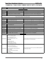
COMMERCIAL TOWER DRYER COMMON SERVICE PARTS
Part #
Description
Where Used
Bindicator
GT3-0036
Bindicator RA4
Low Grain Indicator Located on Upper Sidewall of Dryer
815-1700-5
Bindicator RA6
High Grain Indicator Located on Dryer Roof
756-1150-9
Bindicator Micro-Switch
Replacement Switch for Either Bindicator
769-1225-2
Bindicator Paddle
Replacement Paddle for Either Bindicator
756-1148-3
Bindicator Motor A-H9A-K-HD
Replacement Motor for Either Bindicator
S-8896
Screw, MS #4-40 x 1" SHCS
Connects Extension Shaft or Paddle to Bindicator
S-9100
Nut, Nylock #4-40 ZN GR2
Connects Extension Shaft or Paddle to Bindicator
769-1038-9
Bindicator Cover Gasket
Replacement Gasket for Either Bindicator
GT1-1119
Bindicator Ext. Rod 12"
Standard Extension Rod for RA6 Bindicator
GT1-1473
Bindicator Ext. Shaft 18"
Special Length Extension Rod for RA6 Bindicator
GT1-1120
Bindicator Ext. Rod Shield
Standard Length Rod Shield (Conduit) for RA6 Bindicator
GT1-1474
Bindicator Ext. Shield 18"
Special Length Rod Shield (Conduit) for RA6 Bindicator
806-1667-5
Bindicator Conduit Cap
Rod ShieldCap for RA6 Bindicator
769-1039-7
Bindicator Mounting Plate
Replacement Mounting Plate for RA4 Bindicator
Hi-Limits (Fixed and Adjustible)
GT3-0004
Hi-Limit, Fixed 210° 36' Fixed
Replacement Hi-Limit for Outside or Inside Overheats
756-1026-1
Therm ostat, Hi-Lim it Honeywell T675A 1102 160
to 260D Adjustible
Adjustable Plenum Hi-Limit that Monitors the Burner
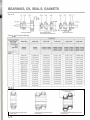
RTD, Thermowells, Probes, Moisture Sensors
756-1865-2
Probe 12"
Temperature Based Moisture Probe Mounted in Outside Sidewall
About 1/3 the Way Up the Dryer
756-1866-0
Therm owell 12"
Therm owell to Protect Moisture Probe
815-1383-0
RTD Probe Mount Weldm ent
Mount for Above Therm owell and Probe
GT3-0090
Sensor, Platinum RTD Honeywell
Temperature Sensor for Burner Mounted on Inside Wall Across
From the Burner
GT3-0139
Wire, 18/2 Shielded
Cable Used for Either Probe Above - Sold Per Foot
602E020-CAT5
Moisture Sensor-Standard Assy (Wide)
W/WR-CAT5E-SH
Top or Bottom Sensor for Tri-Moisture System
WR-CAT5E-SH
Cable, Wire CAT5E Shielded
Cable Used for Tri-Moisture Sensor - Sold per Foot
815-1935-9
Moisture Sensor Housing Assy
Sample Chute Mounted Below Discharge Hopper and Houses
Tri-Moisture Sensor
GT1-1534
Gate, Slide 2-1/4" - Moisture Sensor
Replacement Slide Gate for Moisture Sensor Housing
801-2143-7
Gate, Slide 2-1/2" - Moisture Sensor Box
Replacement Slide Gate for Moisture Sensor Housing
801-2144-5
Gate, Slide 2-3/4" - Moisture Sensor Box
Replacement Slide Gate for Moisture Sensor Housing
801-2101-5
Gate, Slide 3" - Moisture Sensor Box
Replacement Slide Gate for Moisture Sensor Housing
36
Tower Dryer Operations & Service
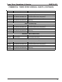
PARTS LIST
COMMERCIAL TOWER DRYER COMMON SERVICE PARTS (CONTINUED)
Part #
Description
Where Used
Burner Control/Maintenance
756-1009-7
Flame Rod
Senses Flame in Burner (Natural Gas or LP)
GT3-0091
Ignitor I-31-1 Spark
Spark Plug for Burner (Natural Gas or LP)
WR-7MM
Wire, 7mm Silicone Ignitor
Wire for Spark Plug - Sold per Foot
GT3-0609
Ignitor Plug Oil (Maxon GP18110/Auburn I-101)
Spark Plug for Burner (Fuel Oil Only)
756-1484-2
Connector, Flame Rod and Ignitor
Connector for Spark Plug or Flam e Rod
756-1485-9
Boot, Flame Rod and Ignitor
Rubber Boot to Cover Connector on Spark Plug or Flame Rod
801-2078-5
Pilot Hood
Mounts on Burner Above Pilot Area to Prevent Flame From
"Dancing" Around
145-1351-9
5/64" x 6" Burner Bit LongBoy
Used to Drill Out Clogged Burner (Natural Gas or LP Only)
Protection Controls Parts
GT3-0134
Flame Pac
Component on Burner Board
GT3-0136
Relay ACF
Component on Burner Board
KD-PEC0020 Transformer SS3CP
Component on Burner Board
GT3-0016
Protectofier Chassis 6642-VA
Complete Burner Board
769-1378-9
Component Tester
Tester for Burner Board Com ponents
GT3-0535
Scanner UV PCII W - Straight
Senses Flame in Burner - Straight (Fuel Oil Only)
GT3-0450
UV Scanner PCII WRA - Right Angle
Senses Flame in Burner - Right Angle (Fuel Oil Only)
GT3-0448
Brown Fiber Nipple
Fuel Oil Burner
769-1029-8
Black 2" Nipple
Fuel Oil Burner
Honeywell
GT3-0083
Motor Modutrol M7284A-1012
756-1002-2
Modutrol Motor Linkage
Mounted at End of Gas Train on Top of CV Valve Controls Gas Flow to Burner
Links Modutrol Motor to CV Valve
Gearboxes and Parts
GSI Only
GT3-1038
Gearbox, Sum itom o C6145Y 90:1 Ratio
Runs Metering Drum
GT3-0138
Motor 5HP 184TC Inverter Duty
Runs Metering Drum
GT1-0670
Plate, Metering Drum Sweep - SS
Leading Edge Plate for Metering Drum
GT1-0671
Clip, Metring Drum Sweep
Clip to Connect Leading Edge to Metering Drum
Zimmerman Only
717-1493-5
Gearbox, Sum itom o 6145 731:1 Ratio
Runs Metering System (12' Dia. Dryers Only)
702-1069-5
Motor, 1HP 3PH 1725 @ 60HZ Super E
Runs Metering System (12' Dia. Dryers Only)
717-1371-3
Gearbox, Sum itom o CVVJ6185DBY 1003:1 Ratio
Runs Metering System (18' Dia. Dryers Only)
702-1068-7
Motor, 1-1/2HP 3PH 1725 @ 60HZ Super E
Runs Metering System (18' Dia. Dryers Only)
717-1440-6
Gearbox, Sum itom o CVVJ6195DBY 1505:1 Ratio
Runs Metering System (24' Dia. Dryers Only)
702-1067-9
Motor, 2HP 3PH 1725 @ 60HZ Super E
Runs Metering System (24' Dia. Dryers Only)
GT3-1024
Gearbox, Sum itom o CVVJ6205DAY 1247:1 Ratio
Runs Metering System (30' Dia. Dryers Only)
702-1047-1
Motor, 3HP 3PH 1725 @ 60HZ Super E
Runs Metering System (30' Dia. Dryers Only)
GT1-1458
Agitator Weldment
Mounts to Back of Sweep to Agitate Grain Under Column
37
Tower Dryer Operations & Service
PARTS LIST
COMMERCIAL TOWER DRYER COMMON SERVICE PARTS (CONTINUED)
Part #
Description
Where Used
Manual Shut-Off Valves
GT3-0014
Valve, DeZurich 2"
Used at Beginning of Gas Train - Size Specific
GT3-0198
Valve, DeZurich 3"
Used at Beginning of Gas Train - Size Specific
707-1141-1
O-Ring 2" Dezurich
Replacem ent Part for 2" DeZurich Valve
707-1140-3
O-Ring 3" Dezurich
Replacem ent Part for 3" DeZurich Valve
D02-0084
Brass Ball Valve 1/4
Used in Return Line Back to Regulator as Balancing Valve
007-1048-3
Brass Ball Valve 3/4
Used in Gas Train (LP Dryers)
TFC-0093
Valve, 1" NPT Bronze Ball - CGA Approved
Used in Gas Train (LP Dryers)
GT3-0034
Valve, Asco 3/8 NC 120V/60HZ (Pilot)
Gas Train Pilot Solenoid
GT3-0719
Solenoid 1-1/4"
Gas Train Solenoid Between Dual Maxons
TF-1536
Solenoid 1-1/2"
Gas Train Solenoid Between Dual Maxons
TF-1296
Solenoid 3/4 Liquid (LP)
Asco Solenoids
Gas Train Solenoid (LP Oil Only)
Pressure Gauges
707-1694-9
Pressure Gauge 30 oz.
Used in Gas Train After CV Valve
GT3-0131
Pressure Gauge 20 oz.
Used in Gas Train After CV Valve
HH-2984
Pressure Gauge 30 lb.
Used in Gas Train for Incom ing Pressure
D02-0103
Pressure Gauge 8-100 lb.
Used in Gas Train (LP Dryers Only)
GT3-0671
Gauge Pressure 2 1/2 Liquid Filled 200 PSI
Used in Gas Train (LP Dryers Only)
007-1829-6
Pressure Gauge 400 lb. (glycerin-filled)
Used in Gas Train (LP Dryers Only)
Regulators and Parts
Rockwell
GT3-0169
Regulator, Gas Equimeter 3" 12112-12
Main Gas Regulator - Size Specific
GT3-0012
Regulator, Gas Equimeter 2.5" 12112-10
Main Gas Regulator - Size Specific
GT3-0471
Regulator, Gas Equimeter 2" 12112-8
Main Gas Regulator - Size Specific
707-1587-5
Regulator Spring Black Rockwell
Standard Spring for Above Regulators
707-1560-2
Regulator Spring Gold Rockwell (cadmium)
Heavier Spring for Above Regulators
Pilot Regulator (All GSI and Zimmerman)
GT3-0033
Regulator Fisher 1/2" (Pilot)
Regulates Gas to the Pilot
Gas Pressure Switches
KD-PES0049 Switch, Low Gas Pressure Honeywell #C6097A1053
Detects Low Gas Pressure in Gas Train
KD-PES0048 Switch, High Gas Pressure Honeywell #C6097B1101
Detects High Gas Pressure in Gas Train
Maxon Shut-Off Valves, Switches and Solenoids
Manual 808 Valves
GT3-0624
Valve, Maxon 2" 808
Used in Gas Train (Switches Separate) - Size Specific
GT3-0206
Valve, Maxon 3" 808-CP
Used in Gas Train (Switches Separate) - Size Specific
GT3-0213
Valve, Maxon 4" F 808-CP
Used in Gas Train (Switches Separate) - Size Specific
GT3-1025
Valve, Maxon 6" 808 VLV
Used in Gas Train (Switches Separate) - Size Specific
Motorized Valves
707-1582-6
Valve, Maxon 2" Motorized 5000 Series
Used in Gas Train (Switches Separate) - Size Specific
GT3-0823
Valve, Maxon 3" Motorized 5000 Series W/VCS-2 Switch
Used in Gas Train - Size Specific
707-1441-5
Valve, Maxon 4" Motorized 5000 Series
Used in Gas Train (Switches Separate) - Size Specific
GT3-1107
Valve, Maxon 6" Motorized 7000 Series
Used in Gas Train (Switches Separate) - Size Specific
38
Tower Dryer Operations & Service
PARTS LIST
COMMERCIAL TOWER DRYER COMMON SERVICE PARTS (CONTINUED)
Part #
Description
Where Used
Single Switch
GT3-0620
GT3-0623
Switch Set VCS-1 (SOV) Maxon VOS-1 #14-23433
Switch Set VCS-1 (VOS-1) Maxon #14-18428
Double Switch
Maxon Switch 3" Valve and Up
Maxon Switch 2" Valve and Below
GT3-0619
GT3-0622
KD-PVA0005
769-1028-0
Switch Set VCS-2 (SOV) Maxon VOS-2 (STO) #14-23434
Double Maxon Switch 3" Valve and up
Switch Set VCS-2 (VOS-2) Maxon #14-18429
Double Maxon Switch 2" Valve and Below
Solenoid 22055
Solenoid 2" and 3" Non-Motorized Maxon
Solenoid 23243
Solenoid 4" Non-Motorized Maxon
CV Valves and Components
GT3-0515
GT3-0132
GT3-0214
CV Valve 2"
Valve, 3" CV Series
Valve, Maxon 4" F CV
Controls Flow of Gas to Burner - Size Specific
Controls Flow of Gas to Burner - Size Specific
Controls Flow of Gas to Burner - Size Specific
GT3-0724
GT3-0726
769-1024-9
769-1197-3
Valve Disc for 2" Maxon CV
Valve Shaft for 2" Maxon CV
Butterfly Shaft 4"
O-Ring 2" Shaft
769-1335-9
Adaptor Bushing MR Valve Arm
Replacem ent Part for 2" CV Valve
Replacem ent Part for 2" CV Valve
Replacem ent Part for 4" CV Valve
Replacem ent Part for 2" CV Valve
Round to Square Bushing in 4" Valve Arm That
Connects Arm to Modutrol Motor
PLC and OIU Parts
PLC Parts
756-1534-4
Filter, Line Active 120V AC 2.5A
Protects PLC from Spikes and Reduces Noise to PLC
756-2159-9
756-1795-1
756-1796-9
PLC, AB Rack 10 Slot
Power Supply, PLC Abradley SLC
PLC, AB SLC 503 CPU 1747-L532
756-1797-7
PLC, AB SLC Memory Module - Programming Required
756-1799-3
756-2161-5
PLC, AB SLC Mix AI/O 2 x 2 Card 1746-NI041
PLC, AB RTD Temperture Module
Back Plane for PLC Cards
Power Suply for PLC 120V AC to 24VDC
PLC Card - CPU (Has Power, Fault, DH485 Lights)
Installs in CPU Card - Memory Module That
Holds Program
First Card to Right of CPU
Second Card to Right of CPU
756-1801-7
GT3-0944
GT3-0810
756-1807-4
PLC, AB DOX16 Card 1746-OW16
PLC, AB IOUTX8 Relay 1746-OX8
PLC, AB DIX16 24VDC 1746-IB16
PLC, AB Slot Cover
16 Point Output Card
8 Point Output Card
16 Point Input Card
Blank - Slot Cover
GT3-1105
Battery, for AB SLC 500 PLC CPU 1747-BA
OIU Parts
Installs in CPU Card - Battery for Back Up
GT3-0945
GT3-0947
OIU, AB PV+ 2711P-RDT10C
OIU, AB Antiglare 2711P-RG10 Film
GT3-0946
Module, OIU AB PV+ LOG. MOD. 2711P-RP
GT3-0974
GT3-0990
GT3-0991
GT3-0973
Module, OIU AB PV+ COMM. MOD. 2711P-RN6
OIU, AB 32MB CF Card 2711-PRW1 - Programming Required
OIU, 64MB RAM 2711-PRR64
IC, PLC AB Micro 1200 24DCIN 16Out 1762-L40BWA
Touchscreen in Control Panel
Antiglare Film for Touchscreen
1st Module Attached to Back of Touchscreen Contains RAM and Compact Flash Card
Stacked on Back of 1st Module
Inserted into 1st Module
Inserted into 1st Module
Micro Processor Located Inside Control Panel
056-2323-6
PLC, AB Advanced Interface Module 1761-NET-AIC
Located Inside of Control Panel - Links PLC
to Micro Processor
756-2163-1
PLC, AB Isolated Link Coupler 1747-AIC-DH485
Located inside of Power Panel - Links PPLC
to Micro Processor
39
Tower Dryer Operations & Service
PARTS LIST
COMMERCIAL TOWER DRYER COMMON SERVICE PARTS (CONTINUED)
Part #
Description
Where Used
Inverters and Line Reactors
Inverters
GT3-0955
Allen Bradley Inverter, VFD AB PF4 2HP/230V
Variable Speed Drive for Unload - Size and Voltage Specific
GT3-0954
Allen Bradley Inverter, VFD AB PF4 2HP/460V
Variable Speed Drive for Unload - Size and Voltage Specific
GT3-0953
Allen Bradley Inverter, VFD AB PF4 5HP/230V
Variable Speed Drive for Unload - Size and Voltage Specific
GT3-0952
Allen Bradley Inverter, VFD AB PF4 5HP/460V
Variable Speed Drive for Unload - Size and Voltage Specific
NOTE: If dryer is equipped with add on Dryer Master ab ove inverters must b e Power Flex40.
Add an A to end of ab ove part num b er for PF40.
Line Reactors
GT3-0975
Reactor, Line 2HP 230V 7.5 Am p
Protects Inverter From Voltage Spikes - Size and Voltage Specific
GT3-0976
Reactor, Line 2HP 460V 3.4 Am p
Protects Inverter From Voltage Spikes - Size and Voltage Specific
GT3-0482
Reactor, Line 5HP 230V 15.2 Am p
Protects Inverter From Voltage Spikes - Size and Voltage Specific
GT3-0129
Reactor, Line 5HP 460V 7.6 Am p
TD-100077
Horn 120 Weatherproof
Alarms When Dryer Shutsdown for Any Reason
756-1213-5
Air Switch Differential JD2-BLUE
Mounted in Power Panel - Prove Blower is Running
815-1783-3
Start/Stop/Pilot Kit
Complete Start/Stop Switch Kit - Used to Control Legs, Conveyors
Protects Inverter From Voltage Spikes - Size and Voltage Specific
Useful/Miscellaneous
GT3-0099
Contact Block for PushButton 1 N.O. CR104PXC1
Replacement N.O. Contact Block for Start Button
756-1415-6
Button, Push-Recess Head GE CR104PB-GOOU3
Replacement Green Start Button (Button Only)
GT3-0100
Contact Block for PushButton 1 N.C. CR104PXCO1
Replacement N.C. Contact Block for Stop Button
756-1414-9
Button, Push-Extended Head GE CR104PB-GOOU2
Replacement Red Stop Button (Button Only)
815-1849-0
Selector Switch, 2POS, 1 N.O./1 N.C.
Complete With 1 N.O./1 N.C. Contact Block
Service Parts Kits
Service Parts Kit Standard
Includes The Following Parts:
1 - Igniter (Natural Gas or LP)
1 - Flam e Rod (Natural Gas or LP)
GT4-SRVSCH1 1 - ACF Relay
1 - Flam e Pac
This Kit Contains essential parts that cannot be bypassed and will
prevent the dryer from running if they fail.
1 - SS3CP Transformer
1 - Adjustible Plenum Hi-Limit
2 - 36' Overheat (Fixed Hi-Limit)
Service Parts Kit Expanded
Includes the Following Parts:
1 - Com plete Kit 1 (GT4-SRVSCH1)
GT4-SRVSCH2 1 - Honeywell Modutrol Motor M7284A 1012
1 - Ounce Gauge
This kit contains all parts in kit 1 plus som e additonal parts that
should be kept on hand.
1 - Sensor, Platinum RTD Honeywell
1 - Air Switch
6 - Burner Drill Bits
40
Tower Dryer Operations & Service
PARTS LIST
COMMERCIAL TOWER DRYER SIDEWALL SHEETS
Part #
Description
Where Used
GSI and ZIMMERMAN Inside Galvanized Sheets
Inside 12' Diameter Dryer
GT1-0405
Sheet, Wall Inside Top 12'
Top Ring
GT1-0406
Sheet, Wall Inside Heat 12'
Heat Section
GT1-0407
Sheet, Wall Inside Cleanout 12'
Inside at Grain Inveter
GT1-0408
Sheet, Wall Inside Cool 12'
Cooling Section
GT1-0409
Sheet, Wall Inside Bottom 12'
Bottom Ring
Inside 18' Diameter Dryer
GT1-0195
Sheet, Wall Inside Top 18'
Top Ring
GT1-0193
Sheet, Wall Inside Heat 18'
Heat Section
GT1-0229
Sheet, Wall Inside Cleanout 18'
Inside at Grain Inveter
GT1-0194
Sheet, Wall Inside Cool 18'
Cooling Section
GT1-0177
Sheet, Wall Inside Bottom 18'
Bottom Ring
GT1-0381
Sheet, Wall Inside Top 24'
Top Ring
GT1-0289
Sheet, Wall Inside Heat 24'
Heat Section
GT1-0382
Sheet, Wall Inside Cleanout 24'
Inside at Grain Inveter
GT1-0383
Sheet, Wall Inside Cool 24'
Cooling Section
GT1-0384
Sheet, Wall Inside Bottom 24'
Bottom Ring
Inside 24' Diameter Dryer
Inside 30' Diameter Dryer
GT1-0706
Sheet, Wall Inside Top 30'
Top Ring
GT1-0707
Sheet, Wall Inside Heat 30'
Heat Section
GT1-0710
Sheet, Wall Inside Bottom 30'
Bottom Ring
Rolled Channel for Above Sheets
GT1-0505
Rolled Plenum Channel - 12'
Horizontal Channel that Stiffeners Inside Sheets
GT1-0008
Rolled Plenum Channel - 18'
Horizontal Channel that Stiffeners Inside Sheets
GT1-0447
Rolled Plenum Channel - 24'
Horizontal Channel that Stiffeners Inside Sheets
GT1-0779
Rolled Plenum Channel - 30'
Horizontal Channel that Stiffeners Inside Sheets
GT1-0011
Splice, Plenum Rolled Channel
Splice Clip for all Rolled Channel
GSI ONLY - Outside Stainless Sheets
Outside 12' Diameter Dryer
GT1-0590-12 Sheet, Wall Punched Blank Solid
Top Rings, Ring Below Grain Inverter, Ring Above Bottom Ring
GT1-0591-12 Sheet, Wall Punched Blank .078
Above Grain Inverter and In Cooling Section
GT1-0592-12 Sheet, Wall Punched Blank .063
Below Grain Inverter but above Cooling Section
GT1-0593-12 Sheet, Wall Punched Blank BTM
Bottom Ring
GT1-1177-12 Sheet, Wall W/Dual Cleanouts
Grain Inverter
Outside 18' Diameter Dryer
GT1-0590-18 Sheet, Wall Punched Blank Solid
Top Rings, Ring Below Grain Inverter, Ring Above Bottom Ring
GT1-0591-18 Sheet, Wall Punched Blank .078
Above Grain Inverter and In Cooling Section
GT1-0592-18 Sheet, Wall Punched Blank .063
Below Grain Inverter but above Cooling Section
GT1-0593-18 Sheet, Wall Punched Blank BTM
Bottom Ring
GT1-1177-18 Sheet, Wall W/Dual Cleanouts
Grain Inverter
41
Tower Dryer Operations & Service
PARTS LIST
COMMERCIAL TOWER DRYER SIDEWALL SHEETS (CONTINUED)
Part #
Description
Where Used
Outside 24' Diameter Dryer
GT1-0590-24 Sheet, Wall Punched Blank Solid
Top Rings, Ring Below Grain Inverter, Ring Above Bottom Ring
GT1-0591-24 Sheet, Wall Punched Blank .078
Above Grain Inverter and In Cooling Section
GT1-0592-24 Sheet, Wall Punched Blank .063
Below Grain Inverter but above Cooling Section
GT1-0593-24 Sheet, Wall Punched Blank BTM
Bottom Ring
GT1-1177-24 Sheet, Wall W/Dual Cleanouts
Grain Inverter
Outside 30' Diameter Dryer
GT1-0590-30 Sheet, Wall Punched Blank Solid
Top Rings, Ring Below Grain Inverter, Ring Above Bottom Ring
GT1-0591-30 Sheet, Wall Punched Blank .078
Above Grain Inverter and In Cooling Section
GT1-0592-30 Sheet, Wall Punched Blank .063
Below Grain Inverter but above Cooling Section
GT1-0593-30 Sheet, Wall Punched Blank BTM
Bottom Ring
GT1-1177-30 Sheet, Wall W/Dual Cleanouts
Grain Inverter
Slide Gates for Above and Below Sheets
GT1-0074
Port, Discharge
Slide Gate Frames at Bottom Ring and at Grain Inverters
GT1-0075
Plate, Discharge
Gates For Slide Gate Frames
ZIMMERMAN Only - Outside Stainless Sheets
Outside 12', 18', 24' and 30' Diameter Dryer
GT1-0590
Sheet, Wall Punched Blank Solid
Top Rings, Ring Below Grain Inverter, Ring Above Bottom Ring
GT1-0591
Sheet, Wall Punched Blank .078
Above Grain Inverter and In Cooling Section
GT1-0592
Sheet, Wall Punched Blank .063
Below Grain Inverter but above Cooling Section
GT1-0593
Sheet, Wall Punched Blank BTM
Bottom Ring
GT1-1177
Sheet, Wall W/Dual Cleanouts
Grain Inverter
42
ELECTRICAL
DIAGRAMS
C
DS1
N.O.
000
I:4.0/00
ACK: DOOR SWITCH 1
LOC: POWER PANEL
C
DS2
N.O.
001
I:4.0/01
ACK: DOOR SWITCH 2
LOC: POWER PANEL
LIMITS UNLESS OTHERWISE SPECIFIED
.0= ±.0625 .00= ±.0312 .000= ±.0156 ANGLES= ±1°
PART NO.
THE GSI GROUP
TERMINALS IN POWER PANEL
FIELD WIRING
1004 E. ILLINOIS ST. ASSUMPTION, IL 62510
TITLE
TOWER DRYER CONTROL PANEL
WIRING DIAGRAM
P/N
MAT'L DESC.
DWG BY
DATE
SCALE
SHEET
HF
DWG NO.
09-9-09
07
OF
18
2010XX-07DS
COMPONENT
MANUALS
Tower Dryer Operations & Service
COMPONENTS
COMPONENT MANUALS
I.
II.
III.
IV.
V.
VI.
VII.
VIII.
IX.
AC FREQUENCY DRIVE
MAXON BURNER
GAS CONTROL VALVE
GAS SHUT-OFF VALVE
GEARBOXES
MODUTROL MOTOR
GAS REGULATORS
ASCO PILOT VALVE
PROTECTOFIER
Tower Dryer Operations & Service
COMPONENTS
I
COMPONENT MANUALS AC FREQUENCY DRIVE
Quick Start
PowerFlex 4 Adjustable
Frequency AC Drive
FRN 3.xx
This Quick Start guide summarizes the basic steps needed to install,
start-up and program the PowerFlex 4 Adjustable Frequency AC Drive.
The information provided Does Not replace the User Manual and is
intended for qualified drive service personnel only.
For detailed PowerFlex 4 information including EMC instructions,
application considerations and related precautions refer to the
PowerFlex 4 User Manual, Publication 22A-UM001… on the CD
supplied with the drive or at www.ab.com/manuals/dr.
General Precautions
!
ATTENTION: The drive contains high voltage capacitors which take
time to discharge after removal of mains supply. Before working on
drive, ensure isolation of mains supply from line inputs [R, S, T (L1,
L2, L3)]. Wait three minutes for capacitors to discharge to safe voltage
levels. Failure to do so may result in personal injury or death.
Darkened display LEDs is not an indication that capacitors have
discharged to safe voltage levels.
!
!
!
!
ATTENTION: Equipment damage and/or personal injury may result
if parameter A092 [Auto Rstrt Tries] or A094 [Start At PowerUp] is
used in an inappropriate application. Do not use this function without
considering applicable local, national and international codes,
standards, regulations or industry guidelines.
ATTENTION: Only qualified personnel familiar with adjustable
frequency AC drives and associated machinery should plan or
implement the installation, start-up and subsequent maintenance of the
system. Failure to comply may result in personal injury and/or
equipment damage.
ATTENTION: This drive contains ESD (Electrostatic Discharge)
sensitive parts and assemblies. Static control precautions are required
when installing, testing, servicing or repairing this assembly.
Component damage may result if ESD control procedures are not
followed. If you are not familiar with static control procedures,
reference A-B publication 8000-4.5.2, “Guarding Against Electrostatic
Damage” or any other applicable ESD protection handbook.
ATTENTION: An incorrectly applied or installed drive can result in
component damage or a reduction in product life. Wiring or application
errors, such as, undersizing the motor, incorrect or inadequate AC
supply, or excessive ambient temperatures may result in malfunction of
the system.
English-2
Mounting Considerations
•
Mount the drive upright on a flat, vertical and level surface.
– Install on 35 mm DIN Rail.
or
– Install with screws.
Minimum Panel Thickness
1.9 mm (0.0747 in.)
•
•
•
Screw Size
M4 (#8-32)
Mounting Torque
1.56-1.96 N-m (14-17 lb.-in.)
Protect the cooling fan by avoiding dust or metallic particles.
Do not expose to a corrosive atmosphere.
Protect from moisture and direct sunlight.
Minimum Mounting Clearances
See page 12 for mounting dimensions.
25 mm
(1.0 in.)
120 mm
(4.7 in.)
120 mm
(4.7 in.)
Mounting Option A
No clearance required
between drives.
Mounting Option B
120 mm
(4.7 in.)
120 mm
(4.7 in.)
Ambient Operating Temperatures
Ambient Temperature
Minimum
Maximum
-10°C (14°F)
(1)
Enclosure Rating
Minimum Mounting
Clearances
IP 20/Open Type
Use Mounting Option A
IP 30/NEMA 1/UL Type 1(1) Use Mounting Option B
Use Mounting Option B
50°C (122°F) IP 20/Open Type
40°C (104°F)
Rating requires installation of the PowerFlex 4 IP 30/NEMA 1/UL Type 1 option kit.
General Grounding Requirements
Important: Remove the MOV to ground jumper if the
drive is installed on an ungrounded distribution system.
Tighten screw after jumper removal.
Jumper
Location
R/L1
S/L2
T/L3
U/T1
V/T2
W/T3
SHLD
CE Conformity
Refer to the PowerFlex 4 User Manual on the CD supplied with the
drive for details on how to comply with the Low Voltage (LV) and
Electromagnetic Compatibility (EMC) Directives.
English-3
Specifications, Fuses and Circuit Breakers
Drive Ratings
Voltage
kW (HP) Amps Range
kVA Amps Fuses
100 - 120V AC (±10%) – 1-Phase Input, 0 - 230V 3-Phase Output
140M Motor
Protectors (2)
Power
Dissipation
IP20 Open
Contactors Watts
22A-V1P5N104
22A-V2P3N104
22A-V4P5N104
22A-V6P0N104
140M-C2E-C10
140M-C2E-C16
140M-D8E-C20
140M-D8E-C25
100-C09
100-C12
100-C23
100-C37
25
30
50
70
140M-C2E-B40
140M-C2E-B63
140M-C2E-C16
140M-C2E-C16
140M-D8E-C25
100-C09
100-C09
100-C12
100-C16
100-C23
25
30
50
75
100
140M-C2E-B63
140M-C2E-B63
140M-C2E-C16
140M-D8E-C20
100-C09
100-C09
100-C12
100-C23
25
30
50
80
140M-C2E-B25
140M-C2E-B40
140M-C2E-C10
140M-C2E-C16
140M-C2E-C16
140M-F8E-C25
100-C09
100-C09
100-C09
100-C12
100-C16
100-C23
25
30
50
80
115
165
140M-C2E-B25
140M-C2E-B40
140M-C2E-B63
140M-C2E-C10
140M-C2E-C16
100-C09
100-C09
100-C09
100-C09
100-C16
30
40
60
90
145
Catalog
Number
Output Ratings
0.2 (0.25)
0.4 (0.5)
0.75 (1.0)
1.1 (1.5)
1.5
2.3
4.5
6.0
Input Ratings
90-126
90-126
90-126
90-126
0.75
1.15
2.25
3.0
Branch Circuit Protection
6.0
9.0
18.0
24.0
10
15
30
40
200 - 240V AC (±10%) – 1-Phase(1) Input, 0 - 230V 3-Phase Output, NO BRAKE
22A-A1P4N103
22A-A2P1N103
22A-A3P6N103
22A-A6P8N103
22A-A9P6N103
0.2 (0.25)
0.4 (0.5)
0.75 (1.0)
1.5 (2.0)
2.2 (3.0)
1.4
2.1
3.6
6.8
9.6
180-265
180-265
180-265
180-265
180-265
0.7
1.05
1.8
3.4
4.8
3.2
5.3
9.2
14.2
19.6
6
10
15
25
30
200 - 240V AC (±10%) – 1-Phase(1) Input, 0 - 230V 3-Phase Output
22A-A1P5N104
22A-A2P3N104
22A-A4P5N104
22A-A8P0N104
0.2 (0.25)
0.4 (0.5)
0.75 (1.0)
1.5 (2.0)
1.5
2.3
4.5
8.0
180-265
180-265
180-265
180-265
0.75
1.15
2.25
4.0
5.0
6.0
10.0
18.0
10
10
15
30
200 - 240V AC (±10%) – 3-Phase Input, 0 - 230V 3-Phase Output
22A-B1P5N104
22A-B2P3N104
22A-B4P5N104
22A-B8P0N104
22A-B012N104
22A-B017N104
0.2 (0.25)
0.4 (0.5)
0.75 (1.0)
1.5 (2.0)
2.2 (3.0)
3.7 (5.0)
1.5
2.3
4.5
8.0
12.0
17.5
180-265
180-265
180-265
180-265
180-265
180-265
0.75
1.15
2.25
4.0
5.5
8.6
1.8
2.5
5.2
9.5
15.5
21.0
3
6
10
15
25
35
380 - 480V AC (±10%) – 3-Phase Input, 0 - 460V 3-Phase Output
22A-D1P4N104
22A-D2P3N104
22A-D4P0N104
22A-D6P0N104
22A-D8P7N104
0.4 (0.5)
0.75 (1.0)
1.5 (2.0)
2.2 (3.0)
3.7 (5.0)
1.4
2.3
4.0
6.0
8.7
340-528
340-528
340-528
340-528
340-528
1.4
2.3
4.0
5.9
8.6
1.8
3.2
5.7
7.5
9.0
Approvals
Input/Output Ratings
Output Frequency: 0-240 Hz (Programmable)
Efficiency: 97.5% (Typical)
Digital Control Inputs (Input Current = 6mA)
SRC (Source) Mode:
18-24V = ON
0-6V = OFF
3
6
10
15
15
SNK (Sink) Mode:
0-6V = ON
18-24V = OFF
C
UL
®
UL508C
CSA 22.2
US No. 14
EMC Directive 89/336/EEC, LV Dir. 73/23/EEC
LV: EN 50178
EMC: EN 61800-3
Analog Control Inputs
4-20mA Analog: 250 ohm input impedance
0-10V DC Analog: 100k ohm input impedance
External Pot: 1-10k ohms, 2 Watt minimum
Control Output (Programmable Output, form C relay)
Resistive Rating: 3.0A at 30V DC, 125V AC and 240V AC
Inductive Rating: 0.5A at 30V DC, 125V AC, and 240V AC
Recommended Fuses and Circuit Breakers
Fuse: UL Class J, CC, T or Type BS88; 600V (550V) or equivalent. Circuit Breakers: HMCP or Bulletin 140U or equivalent.
Protective Features
Motor Protection: I2t overload protection - 150% for 60 Secs, 200% for 3 Secs (Provides Class 10 protection)
Overcurrent: 200% hardware limit, 300% instantaneous fault
Over Voltage:
100-120V AC Input – Trip occurs at 405V DC bus voltage (equivalent to 150V AC incoming line)
200-240V AC Input – Trip occurs at 405V DC bus voltage (equivalent to 290V AC incoming line)
380-460V AC Input – Trip occurs at 810V DC bus voltage (equivalent to 575V AC incoming line)
Under Voltage: 100-120V AC Input – Trip occurs at 210V DC bus voltage (equivalent to 75V AC incoming line)
200-240V AC Input – Trip occurs at 210V DC bus voltage (equivalent to 150V AC incoming line)
380-480V AC Input – Trip occurs at 390V DC bus voltage (equivalent to 275V AC incoming line)
Control Ride Through: Minimum ride through is 0.5 Secs - typical value 2 Secs
Faultless Power Ride Through: 100 milliseconds
Dynamic Braking
Internal brake IGBT included with all ratings except No Brake versions. Refer to Appendix B of the PowerFlex 4 User Manual
on CD for ordering information.
(1)
(2)
200-240V AC - 1-Phase drives are also available with an integral EMC filter. Catalog suffix changes from N103 to N113
and N104 to N114.
Refer to the Bulletin 140M Motor Protectors Selection Guide, publication 140M-SG001… to determine the frame and
breaking capacity required for your application.
English-4
Power Wiring
Power Wire Rating
Recommended Copper Wire
Unshielded 600V, 75°C (167°F) THHN/THWN
15 Mils insulated, dry location
Shielded 600V, 75°C or 90°C (167°F or 194°F) RHH/RHW-2
Belden 29501-29507 or equivalent
Shielded Tray rated 600V, 75°C or 90°C (167°F or 194°F) RHH/RHW-2
Shawflex 2ACD/3ACD or equivalent
Power Terminal Block (A Frame Shown)
Terminal
R/L1 S/L2 T/L3 U/T1 V/T2 W/T3
Description
R/L1, S/L2
1-Phase Input
R/L1, S/L2, T/L3
3-Phase Input
U/T1
To Motor U/T1
V/T2
To Motor V/T2
W/T3
To Motor W/T3
BR+, BR-
Dynamic Brake Resistor Connection [0.75 kW (1 HP) ratings and higher]
BR+ BR-
Switch any two motor leads to
change forward direction.
=
Safety Ground - PE
Power Terminal Block Specifications
Frame
Maximum Wire Size (1)
Minimum Wire Size (1)
A
3.3 mm2 (12 AWG)
0.8 mm2 (18 AWG)
B
5.3 mm2 (10 AWG)
1.3 mm2 (16 AWG)
(1)
Torque
1.7-2.2 N-m (16-19 lb.-in.)
Maximum/minimum sizes that the terminal block will accept - these are not recommendations.
Input Power Conditions
Input Power Condition
Corrective Action
Low Line Impedance (less than 1% line reactance)
•
•
Install Line Reactor(2)
or Isolation Transformer
•
•
Remove MOV jumper to ground.
or Install Isolation Transformer with
grounded secondary if necessary.
Greater than 120 kVA supply transformer
Line has power factor correction capacitors
Line has frequent power interruptions
Line has intermittent noise spikes in excess of 6000V (lightning)
Phase to ground voltage exceeds 125% of normal line to line voltage
Ungrounded Distribution System
(2)
Refer to Appendix B of the PowerFlex 4 User Manual on CD for accessory ordering information.
I/O Wiring Recommendations(3)
Wire Type(s)
Description
Belden 8760/9460
(or equiv.)
0.8 mm2 (18AWG), twisted pair, 100% shield with
drain.
Minimum Insulation Rating
300V
60 degrees C
Belden 8770
0.8 mm2 (18AWG), 3 conductor, shielded for
(140 degrees F)
(or equiv.)
remote pot only.
(3) If the wires are short and contained within a cabinet which has no sensitive circuits, the use of shielded wire may not be
necessary, but is always recommended.
I/O Terminal Block Specifications
Maximum Wire Size (4)
Minimum Wire Size (4)
Torque
2
1.3 mm (16 AWG)
0.13 mm2 (26 AWG)
0.5-0.8 N-m (4.4-7 lb.-in.)
(4) Maximum / minimum that the terminal block will accept - these are not recommendations.
Refer to the PowerFlex 4 User Manual on CD for maximum power and
control cable length recommendations
English-5
Control Terminal Block
(1) Important: I/O Terminal 01 is
always a coast to stop input except
when P036 [Start Source] is set to
“3-Wire” control. In three wire
control, I/O Terminal 01 is controlled
by P037 [Stop Mode]. All other stop
sources are controlled by P037
[Stop Mode].
P036
[Start Source]
Keypad
Per P037
Coast
3-Wire
Per P037
Per P037
2-Wire
Per P037
Coast
RS485 Port
Per P037
Coast
Important: The drive is shipped with
a jumper installed between I/O
Terminals 01 and 11. Remove this
jumper when using I/O Terminal 01
as a stop input.
01
(2) Two wire control shown. For three
05
wire control use a momentary input
on I/O Terminal 02 to
command a start. Use a maintained
input
for I/O Terminal 03 to
change direction.
Relay N.O.
Relay Common
Relay N.C.
Refer to the PowerFlex 4
User Manual on CD for
detailed I/O wiring examples.
I/O Terminal 01
Stop
Stop
02
03
04
06
+24V
+10V
11
12
13
R1
14
R2
15
R3
16
Stop (1)
Typical
Typical
SRC Wiring SNK Wiring
Start/Run FWD (2)
Dir/Run REV
Digital Common
Digital Input 1
Digital Input 2
+24V DC
+10V DC
0-10V In
Analog Common
Potentiometer
must be
1-10k ohm
2 Watt Min.
4-20mA In
RS485 Shield
01 02 03 04 05 06
R1 R2 R3
30V DC 125V AC 240V AC
Resistive
3.0A
3.0A
3.0A
Inductive
0.5A
0.5A
0.5A
SNK
SRC
11
12 13 14 15 16
RS485
(DSI)
(1)
81
No. Signal
Default
Description
Param.
R1
R2
R3
Fault
–
Fault
Normally open contact for output relay.
Common for output relay.
Normally closed contact for output relay.
A055
Source (SRC)
Inputs can be wired as Sink (SNK) or Source (SRC) via DIP Switch
setting.
The factory installed jumper or a normally closed input
must be present for the drive to start.
Relay N.O.
Relay Common
Relay N.C.
Sink/Source DIP Switch
01
Stop(1)
Coast
02
Start/Run FWD
Not Active
03
Direction/Run REV
Not Active
04
Digital Common
–
05
06
Digital Input 1
Digital Input 2
Preset Freq
Preset Freq
11
+24V DC
–
12
+10V DC
–
13
0-10V In(3)
Not Active
14
Analog Common
–
15
4-20mA In(3)
Not Active
16
RS485 (DSI) Shield
–
(3)
A055
P036(1)
P036, P037
Command comes from the integral keypad by default. To
disable reverse operation, see A095 [Reverse Disable]. P036, P037,
A095
For digital inputs. Electronically isolated with digital inputs
from analog I/O.
Program with A051 [Digital In1 Sel].
A051
Program with A052 [Digital In2 Sel].
A052
Drive supplied power for digital inputs.
Maximum output current is 100mA.
Drive supplied power for 0-10V external potentiometer.
P038
Maximum output current is 15mA.
For external 0-10V input supply
P038
(input impedance = 100k ohm) or potentiometer wiper.
For 0-10V In or 4-20mA In. Electronically isolated with
analog inputs from digital I/O.
For external 4-20mA input supply
P038
(input impedance = 250 ohm).
Terminal should be connected to safety ground - PE when
using the RS485 (DSI) communications port.
Only one analog frequency source may be connected at a time. If more than one reference is connected at the same
time, an undetermined frequency reference will result.
English-6
Prepare For Drive Start-Up
!
ATTENTION: Power must be applied to the drive to perform the
following start-up procedures. Some of the voltages present are at
incoming line potential. To avoid electric shock hazard or damage to
equipment, only qualified service personnel should perform the
following procedure. Thoroughly read and understand the procedure
before beginning. If an event does not occur while performing this
procedure, Do Not Proceed . Remove All Power including user
supplied control voltages. User supplied voltages may exist even when
main AC power is not applied to the drive. Correct the malfunction
before continuing.
Before Applying Power to the Drive
❏ 1. Confirm that all inputs are connected to the correct terminals and are
secure.
❏ 2. Verify that AC line power at the disconnect device is within the rated
value of the drive.
❏ 3. Verify that any digital control power is 24 volts.
❏ 4. Verify that the Sink (SNK)/Source (SRC) Setup DIP Switch is set to
match your control wiring scheme. See page 5 for location.
Important: The default control scheme is Source (SRC). The Stop
terminal is jumpered (I/O Terminals 01 and 11) to allow
starting from the keypad. If the control scheme is changed
to Sink (SNK), the jumper must be removed from I/O
Terminals 01 and 11 and installed between I/O Terminals
01 and 04.
❏ 5. Verify that the Stop input is present or the drive will not start.
Important: If I/O Terminal 01 is used as a stop input, the jumper
between I/O Terminals 01 and 11 must be removed.
Applying Power to the Drive
❏ 6. Apply AC power and control voltages to the drive.
❏ 7. Familiarize yourself with the integral keypad features (see next page)
before setting any Program Group parameters.
Start, Stop, Direction and Speed Control
Factory default parameter values allow the drive to be controlled from
the integral keypad. No programming is required to start, stop, change
direction and control speed directly from the integral keypad.
Important: To disable reverse operation, see A095 [Reverse Disable].
If a fault appears on power up, refer to page 11 for an explanation of the
fault code. For complete troubleshooting information, refer to the
PowerFlex 4 User Manual on the CD supplied with the drive.
English-7
Integral Keypad
➋
➊
➌
RUN
FWD
REV
PROGRAM
➍
➏
Menu
VOLTS
AMPS
HERTZ
FAULT
➎
Basic Program Group
Consists of most commonly used
programmable functions.
➑
➐
Description
Display Group (View Only)
Consists of commonly viewed drive operating
conditions.
➒
Advanced Program Group
Consists of remaining programmable functions.
Fault Designator
Consists of list of codes for specific fault
conditions. Displayed only when fault is present.
No. LED
➊ Run/Direction
Status
LED State
Steady Red
Flashing Red
➋
Alphanumeric
Display
Steady Red
Flashing Red
➌
➍
➎
➏
➐
Displayed Units
Steady Red
Description
Indicates drive is running and commanded motor direction.
Drive has been commanded to change direction. Indicates
actual motor direction while decelerating to zero.
Indicates parameter number, parameter value, or fault code.
Single digit flashing indicates that digit can be edited.
All digits flashing indicates a fault condition.
Indicates the units of the parameter value being displayed.
Program Status
Steady Red
Indicates parameter value can be changed.
Fault Status
Flashing Red
Indicates drive is faulted.
Pot Status
Steady Green
Start Key Status Steady Green
No. Key
➑
Name
Escape
Select
Up Arrow
Down Arrow
Enter
➒
Potentiometer
Start
Reverse
Stop
Indicates potentiometer on Integral Keypad is active.
Indicates Start key on Integral Keypad is active.
The Reverse key is also active unless disabled by A095
[Reverse Disable].
Description
Back one step in programming menu.
Cancel a change to a parameter value and exit Program
Mode.
Advance one step in programming menu.
Select a digit when viewing parameter value.
Scroll through groups and parameters.
Increase/decrease the value of a flashing digit.
Advance one step in programming menu.
Save a change to a parameter value.
Used to control speed of drive. Default is active.
Controlled by parameter P038.
Used to start the drive. Default is active.
Controlled by parameter P036.
Used to reverse direction of the drive. Default is active.
Controlled by parameters P036 and A095.
Used to stop the drive or clear a fault.
This key is always active.
Controlled by parameter P037.
English-8
Viewing and Editing Parameters
The last user-selected Display Group parameter is saved when power is removed and is
displayed by default when power is reapplied.
The following is an example of basic integral keypad and display functions. This example
provides basic navigation instructions and illustrates how to program the first Program
Group parameter.
Example Displays
Step
Key(s)
1. When power is applied, the last user-selected
VOLTS
AMPS
Display Group parameter number is briefly
HERTZ
displayed with flashing characters. The display
PROGRAM
FAULT
then defaults to that parameter’s current value.
(Example shows the value of d001 [Output
Freq] with the drive stopped.)
2. Press Esc once to display the Display Group
parameter number shown on power-up. The
parameter number will flash.
VOLTS
AMPS
HERTZ
PROGRAM
FAULT
3. Press Esc again to enter the group menu. The
group menu letter will flash.
VOLTS
AMPS
HERTZ
4. Press the Up Arrow or Down Arrow to scroll
through the group menu (d, P and A).
or
5. Press Enter or Sel to enter a group. The right
digit of the last viewed parameter in that group
will flash.
or
6. Press the Up Arrow or Down Arrow to scroll
through the parameters that are in the group.
or
7. Press Enter or Sel to view the value of a
parameter. If you do not want to edit the value,
press Esc to return to the parameter number.
or
8. Press Enter or Sel to enter program mode to
edit the parameter value. The right digit will
flash and the Program LED will illuminate if the
parameter can be edited.
or
9. Press the Up Arrow or Down Arrow to change
the parameter value. If desired, press Sel to
move from digit to digit or bit to bit. The digit or
bit that you can change will flash.
or
PROGRAM
FAULT
VOLTS
AMPS
HERTZ
PROGRAM
FAULT
VOLTS
AMPS
HERTZ
PROGRAM
FAULT
VOLTS
AMPS
HERTZ
PROGRAM
FAULT
10. Press Esc to cancel a change. The digit will
stop flashing, the previous value is restored and
the Program LED will turn off.
Or
Press Enter to save a change. The digit will stop
flashing and the Program LED will turn off.
VOLTS
AMPS
HERTZ
PROGRAM
11. Press Esc to return to the parameter list.
Continue to press Esc to back out of the
programming menu.
If pressing Esc does not change the display,
then d001 [Output Frequency] is displayed.
Press Enter or Sel to enter the group menu.
FAULT
VOLTS
AMPS
HERTZ
PROGRAM
FAULT
English-9
See the PowerFlex 4 User Manual on CD for more information on parameters.
Display Group Parameters
No.
Parameter
Min/Max
Display/Options
d001
d002
d003
d004
d005
d006
[Output Freq]
[Commanded Freq]
[Output Current]
[Output Voltage]
[DC Bus Voltage]
[Drive Status]
0.0/[Maximum Freq]
0.0/[Maximum Freq]
0.00/(Drive Amps × 2)
0/Drive Rated Volts
Based on Drive Rating
0/1 (1 = Condition True)
0.1 Hz
0.1 Hz
0.01 Amps
1 VAC
1 VDC
Bit 3
Decelerating
F1
d007- [Fault x Code]
d009
d010 [Process Display]
d012 [Control Source]
F2/F122
d013 [Contrl In Status]
0/1 (1 = Input Present)
d014 [Dig In Status]
0/1 (1 = Input Present)
d015 [Comm Status]
0/1 (1 = Condition True)
d016
d017
d018
d019
d020
d021
d024
1.00/99.99
1001/9999
0/9999 Hrs
0/FFFF
0.0/100.0%
0.0/100.0%
0/120 degC
[Control SW Ver]
[Drive Type]
[Elapsed Run Time]
[Testpoint Data]
[Analog In 0-10V]
[Analog In 4-20mA]
[Drive Temp]
0.00/9999
0/9
Bit 2
Accelerating
0.01 – 1
Digit 1 = Speed Command
(See P038; 9 = “Jog Freq”)
Bit 3
Bit 2
Reserved
Stop Input
Bit 3
Bit 2
Reserved
Reserved
Bit 3
Bit 2
Fault Occurred RS485 Option
0.01
1
1 = 10 Hrs
1 Hex
0.1%
0.1%
1 degC
Bit 1
Forward
Bit 0
Running
Digit 0 = Start Command
(See P036; 9 = “Jog”)
Bit 1
Bit 0
Dir/Run REV
Start/Run FWD
Bit 1
Bit 0
Digital In2 Sel Digital In1 Sel
Bit 1
Bit 0
Transmitting
Receiving
Smart Start-Up with Basic Program Group Parameters
The Program Group contains the most commonly used parameters.
= Stop drive before changing this parameter.
No.
Parameter
Min/Max
Display/Options
Default
P031 [Motor NP Volts]
20/Drive Rated Volts
1 VAC
Based on Drive Rating
Set to the motor nameplate rated volts.
P032 [Motor NP Hertz]
10/240 Hz
1 Hz
60 Hz
Set to the motor nameplate rated frequency.
P033 [Motor OL Current] 0.0/(Drive Rated Amps×2) 0.1 Amps
Based on Drive Rating
Set to the maximum allowable motor current.
P034 [Minimum Freq]
0.0/240.0 Hz
0.1 Hz
0.0 Hz
Sets the lowest frequency the drive will output continuously.
P035 [Maximum Freq]
0/240 Hz
1 Hz
60 Hz
Sets the highest frequency the drive will output.
3 = “2-W Lvl Sens” 0
P036 [Start Source]
0/5
0 = “Keypad”(1)
4 = “2-W Hi Speed”
Sets the control scheme used to start the drive. 1 = “3-Wire”
5 = “Comm Port”
2 = “2-Wire”
(1)
When active, the Reverse key is also active unless disabled by A095 [Reverse Disable].
0
4 = “Ramp”
P037 [Stop Mode]
0/7
0 = “Ramp, CF”(1)
(1)
Active stop mode for all stop sources [e.g. keypad, 1 = “Coast, CF” (1) 5 = “Coast”
6
=
“DC
Brake”
2
=
“DC
Brake,
CF”
run forward (I/O Terminal 02), run reverse (I/O
(1)
Terminal 03), RS485 port] except as noted below. 3 = “DCBrkAuto,CF” 7 = “DC BrakeAuto”
Important: I/O Terminal 01 is always a coast to stop input except when P036 [Start Source] is set for “3-Wire” control.
When in three wire control, I/O Terminal 01 is controlled by P037 [Stop Mode].
(1) Stop input also clears active fault.
3 = “4-20mA Input” 0
P038 [Speed Reference] 0/5
0 = “Drive Pot”
4 = “Preset Freq”
1 = “InternalFreq”
Sets the source of the speed reference to the
2
=
“0-10V
Input”
5 = “Comm Port”
drive.
Important: When A051 or A052 [Digital Inx Sel] is set to option 2, 4, 5, 6, 13 or 14, and the digital input is active, A051
or A052 will override the speed reference commanded by this parameter. Refer to Chapter 1 of the PowerFlex 4 User
Manual on CD for details.
P039 [Accel Time 1]
0.0/600.0 Secs
0.1 Secs
10.0 Secs
Sets the rate of accel for all speed increases.
P040 [Decel Time 1]
0.1/600.0 Secs
0.1 Secs
10.0 Secs
Sets the rate of decel for all speed decreases.
P041 [Reset To Defalts]
0/1
0 = “Idle State”
0
Resets all parameter values to factory defaults. 1 = “Reset Defaults”
English-10
See the PowerFlex 4 User Manual on CD for more information on parameters.
Advanced Group Parameters
No.
Min/Max
Display/Options
A051 [Digital In1 Sel]
I/O Terminal 05
A052 [Digital In2 Sel]
I/O Terminal 06
0/26
A055 [Relay Out Sel]
0/21
0 = “Not Used”
1 = “Acc 2 & Dec 2”
2 = “Jog”
3 = “Aux Fault”
4 = “Preset Freq”
5 = “Local”
6 = “Comm Port”
7 = “Clear Fault”
0 = “Ready/Fault”
1 = “At Frequency”
2 = “MotorRunning”
3 = “Reverse”
4 = “Motor Overld”
5 = “Ramp Reg”
A056
A067
A068
A069
A070
A071
A072
A073
Parameter
Default
8 = “RampStop,CF”
9 = “CoastStop,CF”
10 = “DCInjStop,CF”
11 = “Jog Forward”
12 = “Jog Reverse”
13 = “10V In Ctrl”
14 = “20mA In Ctrl”
26 = “Anlg Invert”
6 = “Above Freq”
7 = “Above Cur”
8 = “Above DCVolt”
9 = “Retries Exst”
10 = “Above Anlg V”
20 = “ParamControl”
21 = “NonRec Fault”
[Relay Out Level]
0.0/9999
0.1
[Accel Time 2]
0.0/600.0 Secs
0.1 Secs
[Decel Time 2]
0.1/600.0 Secs
0.1 Secs
[Internal Freq]
0.0/240.0 Hz
0.1 Hz
[Preset Freq 0](1)
0.0/240.0 Hz
0.1 Hz
[Preset Freq 1]
[Preset Freq 2]
[Preset Freq 3]
(1) To activate [Preset Freq 0] set P038 [Speed Reference] to option 4.
4
0
0.0
20.0 Secs
20.0 Secs
60.0 Hz
0.0 Hz
5.0 Hz
10.0 Hz
20.0 Hz
(2)
Input State of Digital In 1
Input State of Digital In 2
Frequency Source
Accel / Decel Parameter Used
(I/O Terminal 05)
(I/O Terminal 06)
0
0
[Preset Freq 0]
[Accel Time 1] / [Decel Time 1]
1
0
[Preset Freq 1]
[Accel Time 1] / [Decel Time 1]
0
1
[Preset Freq 2]
[Accel Time 2] / [Decel Time 2]
1
1
[Preset Freq 3]
[Accel Time 2] / [Decel Time 2]
(2)
When a Digital Input is set to “Accel 2 & Decel 2”, and the input is active, that input overrides the settings in this table.
A078
A079
A080
A081
A082
[Jog Frequency]
[Jog Accel/Decel]
[DC Brake Time]
[DC Brake Level]
[DB Resistor Sel]
0.0/[Maximum Freq]
0.1/600.0 Secs
0.0/90.0 Secs
0.0/(Drive Amps × 1.8)
0/99
0.1 Hz
0.1 Secs
0.1 Secs
0.1 Amps
0 = Disabled
1 = Normal RA Res
2 = NoProtection
3-99 = % of Duty Cycle
10.0 Hz
10.0 Secs
0.0 Secs
Amps × 0.05
0
A083 [S Curve %]
0/100%
A084 [Start Boost]
1/14
Only active when A125 [Torque Perf Mode] is
set to 0 “V/Hz”.
A088 [Maximum Voltage]
A089 [Current Limit]
A090 [Motor OL Select]
A091
A092
A093
A094
[PWM Frequency]
[Auto Rstrt Tries]
[Auto Rstrt Delay]
[Start At PowerUp]
1%
0% (Disabled)
Settings in % of base voltage.
8
7 (5 HP Drives)
0 = “Custom V/Hz”
Variable Torque Constant Torque
1 = “30.0, VT”
5 = “0.0, no IR”
10 = “10.0, CT”
2 = “35.0, VT”
6 = “0.0”
11 = “12.5, CT”
3 = “40.0, VT”
7 = “2.5, CT”
12 = “15.0, CT”
4 = “45.0, VT”
8 = “5.0, CT”
13 = “17.5, CT”
9 = “7.5, CT”
14 = “20.0, CT”
20/Rated Volts
1 VAC
Rated Volts
0.1/(Drive Amps × 1.8) 0.1 Amps
Amps × 1.5
0/2
0 = “No Derate”
1 = “Min Derate”
0
2 = “Max Derate”
2.0/16.0 kHz
0.1 kHz
4.0 kHz
0/9
1
0
0.0/300.0 Secs
0.1 Secs
1.0 Secs
0/1
0 = “Disabled”
1 = “Enabled”
0
A095 [Reverse Disable]
0/1
0 = “Rev Enabled”
1 = “Rev Disabled”
0
A096 [Flying Start En]
A097 [Compensation]
0/1
0/3
1 = “Enabled”
2 = “Mechanical”
3 = “Both”
0
1
A098 [SW Current Trip]
A099 [Process Factor]
A100 [Fault Clear]
0.0/(Drive Amps × 2)
0.1/999.9
0/2
0 = “Disabled”
0 = “Disabled”
1 = “Electrical”
0.1 Amps
0.1
0 = “Ready/Idle”
A101 [Program Lock]
0/1
0 = “Unlocked”
1 = “Reset Fault”
2 = “Clear Buffer”
1 = “Locked”
0.0 (Disabled)
30.0
0
0
English-11
See the PowerFlex 4 User Manual on CD for more information on parameters.
No.
Parameter
Min/Max
0/FFFF
A102 [Testpoint Sel]
A103 [Comm Data Rate](3) 0/5
Display/Options
Default
400
3
A106 [Comm Loss Time]
A107 [Comm Format](3)
0.1/60.0
0/5
A110 [Anlg In 0-10V Lo]
0.0/100.0%
1 Hex
0 = “1200”
1 = “2400”
2 = “4800”
1
0 = “Fault”
1 = “Coast to Stop”
0.1
0 = “RTU 8-N-1”
1 = “RTU 8-E-1”
2 = “RTU 8-O-1”
0.1%
A111 [Anlg In 0-10V Hi]
0.0/100.0%
0.1%
100.0%
A112 [Anlg In4-20mA Lo]
0.0/100.0%
0.1%
0.0%
A113 [Anlg In4-20mA Hi]
0.0/100.0%
0.1%
100.0%
A104 [Comm Node Addr](3) 1/247
A105 [Comm Loss Action] 0/3
3 = “9600”
4 = “19.2K”
5 = “38.4K”
2 = “Stop”
3 = “Continu Last”
3 = “RTU 8-N-2”
4 = “RTU 8-E-2”
5 = “RTU 8-O-2”
A114 [Slip Hertz @ FLA] 0.0/10.0 Hz
0.1 Hz
A115 [Process Time Lo]
0.00/99.99
0.01
A116 [Process Time Hi]
0.00/99.99
0.01
(3)
Power to drive must be cycled before any changes will affect drive operation.
100
0
5.0
0
0.0%
2.0 Hz
0.00
0.00
Fault Codes
To clear a fault, press the Stop key, cycle power or set A100 [Fault Clear] to 1 or 2.
No.
Fault
Description
F2
F3
F4
F5
Auxiliary Input(1)
Power Loss
UnderVoltage(1)
OverVoltage(1)
F6
Motor Stalled(1)
F7
Motor Overload(1)
F8
Heatsink OvrTmp(1)
F12
HW OverCurrent(1)
F13
F33
F38
F39
F40
F41
F42
F43
F48
Ground Fault
Auto Rstrt Tries
Phase U to Gnd
Phase V to Gnd
Phase W to Gnd
Phase UV Short
Phase UW Short
Phase VW Short
Params Defaulted
Check remote wiring.
Monitor the incoming AC line for low voltage or line power interruption.
Monitor the incoming AC line for low voltage or line power interruption.
Monitor the AC line for high line voltage or transient conditions. Bus overvoltage can also be
caused by motor regeneration. Extend the decel time or install dynamic brake option.
Increase [Accel Time x] or reduce load so drive output current does not exceed the current set
by parameter A089 [Current Limit].
An excessive motor load exists. Reduce load so drive output current does not exceed the
current set by parameter P033 [Motor OL Current].
Check for blocked or dirty heat sink fins. Verify that ambient temperature has not exceeded
40°C (104°F) for IP 30/NEMA 1/UL Type 1 installations or 50°C (122°F) for Open type installations.
Check fan.
Check programming. Check for excess load, improper DC boost setting, DC brake volts set too
high or other causes of excess current.
Check the motor and external wiring to the drive output terminals for a grounded condition.
Correct the cause of the fault and manually clear.
Check the wiring between the drive and motor. Check motor for grounded phase.
Replace drive if fault cannot be cleared.
Check the motor and drive output terminal wiring for a shorted condition.
Replace drive if fault cannot be cleared.
The drive was commanded to write default values to EEPROM. Clear the fault or cycle power to
the drive. Program the drive parameters as needed.
F63
Check load requirements and A098 [SW Current Trip] setting.
F64 Drive Overload
Reduce load or extend Accel Time.
F70 Power Unit
Cycle power. Replace drive if fault cannot be cleared.
F81 Comm Loss
If adapter was not intentionally disconnected, check wiring to the port. Replace wiring, port
expander, adapters or complete drive as required. Check connection. An adapter was
intentionally disconnected. Turn off using A105 [Comm Loss Action].
F100 Parameter Checksum Restore factory defaults.
F122 I/O Board Fail
Cycle power. Replace drive if fault cannot be cleared.
SW OverCurrent(1)
(1)
Auto-Reset/Run type fault. Configure with parameters A092 and A093.
Tower Dryer Operations & Service
COMPONENTS
II
COMPONENT MANUALS
MAXON BURNER
Bulletin 5550
Series NP-LE AIRFLO® Burners
• Designed for direct-fired make-up air and process applications
• Improved emissions performance over Maxon's standard NP AIRFLO® Burner, with
significantly lower levels of CO and NO2
• Higher capacity - up to 1,000,000 Btu/hr/ft
• Shorter flame length
• Easily meets ANSI/CSA standards
• Available in low pressure version and corrosion-resistant materials
m
CORPORATION
201 East 18th Street, P.O. Box 2068, Muncie, Indiana, 47307-0068. Phone: (765) 284-3304. Fax (765) 286-8394
Page 5552
Design and Application Details
Specifications
Input Rating
Up to 1,000,000 Btu/hr/ft
Airstream Profile Differential Pressure
0.3 to 1.0 "wc
Pilot Capacity
25,000 Btu/hr @ 4"-6" wc
Burner Turndown
30:1
Maximum Upstream Temperature
600°F cast iron; 450°F aluminum
Maximum Downstream Temperature
1000°F cast iron; 850°F aluminum
Maximum Temperature Rise
760°F
Minimum Upstream Oxygen
18% O2
Burner Bodies
NP1-LE Cast iron and aluminum
NP2-LE Cast iron
Burner Section Configurations
6" Straight
12" Straight
12" Straight with Back Inlet
6" x 12" Tee
6" x 6" Elbow (cast iron only)
36" Back Inlet (12" x 12" H-configuration)
Mixing Plates
430 Stainless Steel
Assembly Material Availability
NP1-LE:
- Standard - Cast Iron Body, Cast Iron End Plates
- AL - Aluminum Body, Cast Iron End Plates
- ALSS - Aluminum Body & Back-up Bars, Nickle Plated End Plates, Stainless Steel Fasteners
NP2-LE:
- Standard - Cast Iron Body, Cast Iron End Plates
Spark Ignitor
UV Flame Scanner Connection
Flame Rod
Adjustable Pilot Orifice
Division Plate
External Mounting Assemblies
Accessories
CO Emissions Profile
NO2 Emissions Profile
Nominal Conditions NP1-LE
CO vs. Temperature Rise
Nominal Conditions
NP1-LE
NO2 vs. Temperature Rise
0.70
5.0
4.5
4.0
Natural Gas
0.50
CO ppm (as measured)
NO2 ppm (as measured)
0.60
Propane
0.40
0.30
0.20
Natural
Gas
Propane
3.5
3.0
2.5
2.0
1.5
1.0
0.10
0.5
0.00
0.0
0
20
40
60
80
100
120
Temperature Rise (F)
140
160
180
200
0
20
40
60
80
100
120
Temperature Rise (F)
140
160
180
200
Page 5553
Typical Applications for Maxon Series NP-LE
AIRFLO® Burners
Packaged Make-up Air Systems
with 100% Outside Air
Packaged Make-up Air Systems
with Partially Recirculated Air
NP-LE AIRFLO® Burner
NP-LE AIRFLO® Burner
Fan
Fan
Fresh
Air
Fresh
Air
Return
Air
Supply
Air
Supply
Air
Single-stage Burner Heated Paint Spray
Booths with Re-heat Option
Humidity Controlled, 2-stage Burner
Heated Paint Spray Booths
Air Intake
Air Intake
Preheat
NP-LE AIRFLO® Burner
Reheat
NP-LE AIRFLO® Burner
(If Required)
Staged
NP-LE AIRFLO® Burner
Fan
Fan
Bag
Filters
Supply
Air
Humidifier
Drying, Baking & Curing Operations
Bag
Filters
Supply
Air
Humidifier
Grain Dryers
NP-LE AIRFLO® Burner
Filter
Fan
Grain Bin
Fresh
Air
Heated
Air
Hot Air
Chamber
NP-LE
AIRFLO® Burner
NP-LE AIRFLO® Burner
Filter
Fan
Fresh
Air
Fan
Heated
Air
Cooling
Chamber
Intake
Air
Page 5554
Design and Application Details
System components normally used in conjunction with a Maxon NP-LE
AIRFLO® Burner application
Intake Louvers
Profile Plate
NP-LE AIRFLO® Burner
1
Duct Walls
2
4
3
10
Bl
oc
k&
Bl
ee
dM
ain
n
Ga
sT
rai
ot
Pil
n
s
Ga
i
Tra
7
8
5
6
9
Main
Volume
Fan
Legend:
Item
Number
m
CORPORATION
Description
1
Outside ther mostat
2
Intake high temperature limit switch
3
Control valve
4
Vent valve
5
Strainer
6
Dr ip leg
7
Differential air switch
8
High temperature switch
9
Discharge air ther mostat
10
Sequencing Control Panel
1/01
201 East 18th Street, P.O. Box 2068, Muncie, Indiana, 47307-0068. Phone: (765) 284-3304. Fax (765) 286-8394
Page 5550-S-1
Series NP-LE AIRFLO® Burners
Installation Instructions
General
Important: Do not discard packing material until
all loose items are accounted for.
Avoid bending or damaging the steel mixing plates
of your Series NP-LE AIRFLO® Burner during
uncrating and installation.
These burners are used
for the heating of fresh air
in motion. Mount the
burners so they fire parallel
to and in the same direction as the movement of
the air (see sketch 1 at
right).
Velocity and flow of air
at operating temperature
must be uniform. Minimum
silhouette profile plates of
6" should be installed in
duct to completely surround burner assembly.
Sketch 2 shows the burner suspended from a strap
iron frame using Maxon USB support brackets. Note
that rigid mounting is avoided by the bracket hole
which slips loosely over a bolt or steel rod attached to
the support. Gas piping would need independent
support.
Sketch 3 shows the burner assembly resting upon
angle iron brackets and not attached to them in any
way. Be sure the angle iron supports allow the burner
flanges to expand and contract. Gas manifolding
would be independently supported and prevent
forward movement of the burner.
Supports
Series NP-LE AIRFLO® Burner assemblies must be
adequately supported and positioned.
Avoid rigid mounting. Burner assembly expands
and contracts with temperature variations.
Maintain smooth, even air flow over the burner by
designing supports to provide minimum interference,
deflection and turbulence.
The sketches below show typical installation and
support methods:
Strap Iron
Frame
Maxon
Support
Brackets
Air
Movement
Allow Space
for Burner
Expansion
2
Air
Movement
3
Sketch 4 shows simple strap iron used to support
the burner. Note that narrow edge of strap faces air
flow to avoid undue turbulence.
Sketch 5 shows gas manifolding used to support
the burner. If there are
multiple inlets, you must
avoid rigid connection by
Angle
Iron
using the oversize U-bolt
Support
(loosely drawn up) illustrated.
Rod
Support for down-fired
burners can be accomplished
Support
as shown in the illustration at
Brackets
3/4"
right. Always avoid rigid
Hole
mounting.
Sketch 6 shows Maxon
Air
Air
Movement
Movement
USB support brackets
suspending the burner from
an overhead angle iron.
Sketch 7 shows an alternate arrangement which
offers the advantage of more
controlled positioning.
6
Bolt or Rod
Long enough to permit
brackets to move with
burner expansion
6/03
Strap Iron
Frame
Angle Iron
Support
Maxon practices a policy of continuous product improvement. It reserves the right to alter specifications without prior notice.
INDUSTRIAL COMBUSTION EQUIPMENT AND VALVES
m
CORPORATION
MUNCIE, INDIANA, USA
Series NP-LE AIRFLO® Burners
Page 5550-S-2
Installation Instructions (cont'd.)
Gas Train
See piping layout below to identify various typical
system components.
Pipe size of gas line must be large enough to
assure ample fuel pressure at maximum system
capacity. Burner capacity is totally dependent on fuel
differential being maintained. (See capacity/specification data for the actual fuel pressure required at the
burner to achieve its rated capacity.)
Clean fuel lines are essential to prevent blockage
of pipe train components or burner gas ports. All dirt,
scale and pipe dope should be blown out of any gas
line before actually connecting to the burner system.
Main shut-off cock should be upstream of both
system regulator and pilot line take-off. Use it to shut
off fuel to both pilot and main burner during extended
shutdown periods. Maxon Control Valves are not
intended for tight shutoff. Main system shut-off should
always be accomplished with a manual fuel cock.
Main gas regulator is essential to maintain a
uniform system supply pressure. A separate regulator
should be provided in the branch leading to each
burner system if more than one is served by a common main. Size regulator for full system capacity at
required pressure, including pipe train losses.
The gas train piping illustrated should be installed
as close to the burner as possible.
Pilot take-off should be upsteam of main gas
regulator, but downstream of main gas cock. It
normally includes pilot shut-off cock, pilot gas regula-
tor and pilot solenoid valves. For pilot adjustment, a
fixed orifice, or adjustable orifice is recommended at or
near the pilot gas inlet.
Fuel shut-off valves, when properly wired to a
safety control system, shuts the fuel supply off when a
hazardous operating condition is sensed by your
control circuit. Manual reset valves require operator
attendence each time the system is started up (or
restarted after a trip-out). Motorized shut-off valves
permit automatic start/restart when used with appropriate control system.
Fuel control valve controls burner heat release by
throttling gas flow to it. It should include provision for
an adjustable minimum and throttling over a turndown
range that matches burner capabilities. The illustration shows a Series "CV" Flow Control Valve; but
adjustable gradient SYNCHRO® and/or "Q" Flow
Control Valves may be used.
Gas pressure test connections are provided in
most Series NP-LE Burner end plate sets, but it is
also helpful to provide an additional test connection in
the piping between main gas regulator and fuel
control valve. All connections must be plugged unless
an actual pressure measuring device (gauge or
manometer) is being used.
Maxon assumes no responsibility for the use
or misuse of the piping layouts shown.
Specific piping and wiring diagrams should
always be submitted to the appropriate
agencies for approval on each application.
Typical Piloted System
Strap Iron
Frame
Support
Brackets
Air
Movement
Air
Movement
7
m
CORPORATION
MUNCIE, INDIANA, USA
Maxon practices a policy of continuous product improvement. It reserves the right to alter specifications without prior notice.
INDUSTRIAL COMBUSTION EQUIPMENT AND VALVES
Series NP-LE AIRFLO® Burners
Page 5550-S-3
Start-Up Instructions
Read complete instructions before proceeding, and
familiarize yourself with all the system's equipment
components. Verify that your equipment has been
installed in accordance with the original manufacturer's current instructions.
CAUTION: Initial adjustment and light-off should
be undertaken only by trained and experienced
personnel familiar with combustion systems,
with control/safety circuitry and with knowledge
of the overall installation. Instructions provided
by the company and/or individuals responsible
for the manufacture and/or overall installation of
complete system incorporating Maxon burners
take precedence over these provided by Maxon.
If Maxon instructions conflict with any codes or
regulations, contact Maxon Corporation before
attempting start-up.
6.
For initial system start-up:
1.
Close all burner fuel valves and/or cocks. Make
preliminary adjustments to fuel regulators.
Check all electric circuitry. Verify that all safety
devices and interlocks are operable and functioning within their respective settings/ranges.
Be sure all manifolds are tight and that test ports
are plugged if not being used.
Check that all duct and chamber dampers are
properly positioned and locked into operating
positions.
Start main volume air fan. Check for proper
motor rotation and impeller direction. Verify all
safety interlocks are working. Allow air handling
equipment to run adequate purge of manifold
and combustion chamber plenums. Verify air
volume and velocity across burner element to be
within burner operating specifications.
2.
3.
4.
CAUTION: Do not by-pass control panel timers
typically controlling sequential operations.
5.
6/03
Disconnect the automatic control motor linkage
from your Maxon Control Valve by loosening the
control motor's connecting rod from the valve's
toggle linkage. Initial start-up adjustment should
only be accomplished during a "manual" control
mode. Manually set and secure control valve in
its "minimum" position.
7.
8.
To light and adjust gas pilot: Pilot gas regulator
should initially be set at 2-5” wc. With pilot gas
solenoid valves closed, open main fuel gas and
pilot gas cock. Energize spark ignitor and open
pilot gas solenoid. Turn adjustable orifice screw
out (counter-clockwise) several turns from its
fully seated position or adjust regulator pressure
when fixed orifice is used. Observe pilot ignition
through a sight port and/or by viewing micro-amp
signal metered from flame safeguard relay circuit.
Refine pilot setting for a hard blue flame (and/or
strongest micro-amp signal) by adjusting gas
flow through pilot orifice and/or pilot regulator.
Prepare to ignite main burner by adjusting main
gas regulator to approximately midpoint of its
adjustment range. Linkage arrangement for the
use of Series "CV" Gas Control Valve is illustrated above for a typical control motor. Arrange
accordingly.
With control valve at "minimum," ignite main
burner by opening main fuel shut-off valves.
Adjust main gas regulator to give the desired
outlet pressure. Refine pilot adjustment if it has
been affected. Adjust burner "minimum" by
turning in on the minimum stop screw of the gas
control valve until stable flame appears in the
narrow zipper channel at the base of burner
mixing plates.
Maxon practices a policy of continuous product improvement. It reserves the right to alter specifications without prior notice.
INDUSTRIAL COMBUSTION EQUIPMENT AND VALVES
m
CORPORATION
MUNCIE, INDIANA, USA
Series NP-LE AIRFLO® Burners
Page 5550-S-4
Start-Up Instructions (cont'd.)
A good minimum fire should provide uniform
flame across the entire burner face, contained
within the zipper flame channel at the base of
burner mixing plates. Any thin spots or gaps
indicate uneven air velocity over the burner
which must be corrected or a higher minimum
fire established by continuing to turn in on the
minimum stop screw. (See drawing on page
5550-S-2.)
NOTE: If your Maxon NP-LE AIRFLO® Burner
was furnished with an adjustable gradient type
Series "Q" or SYNCHRO® Control Valve
instead of a Series "CV" Valve, refer to step
8A through 8I for specific instructions and
differences in adjustment procedures.
For Series “CV” Valves, skip to step 9.
Adj. Screws
(under cover)
Handle for
Manual
Operation
Position
Indicator
Pointer
Locking Screw
for manual
operation
A. From step #5, the automatic control motor
linkage has already been disconnected from
your adjustable gradient type control valve
and the valve is at its "minimum" position.
B. Open fuel supply and begin adjustment of
appropriate adjustable gradient valve by
turning in minimum (or lowest numbered)
screw until desired flame is achieved. (Main
fuel regulator may need adjusted at this
point.)
C. Once your flame is established and refined
at this position, and without advancing the
screw carrier quadrant higher, screw all
remaining screws down to at least the same
level as your first adjusted screw.
NOTE: A preliminary setting can be established with all the remaining adjusting
screws. Generally, each succeeding screw
needs to be screwed in approximately one
full turn deeper than its preceeding screw. A
smooth "stair-step" gradient pre-set at this
point from low to high will simplify the
m
CORPORATION
MUNCIE, INDIANA, USA
9.
remaining adjustment steps.
D. Without advancing the SYNCHRO® Valve
quadrant, screw down on #2 screw (one or
two turns). Then slowly advance the
SYNCHRO® Valve quadrant to the #2
position. Refine flame appearance at this
new position #2.
E. Turn all higher-numbered screws in at least
as far as the one just adjusted, then turn
next one in as necessary to achieve desired
flame while rotating valve mechanism to that
position on indicator strip.
F. Repeat for each remaining screw.
NOTE: To avoid possible damage to cam
strips, always turn all higher-numbered
screws in as far as the last one adjusted.
G. Refine adjustment as needed, always
turning valve so that position indicator
matches screw being adjusted.
For more fuel, turn screw in (clockwise). for
less fuel, turn screw out (counter-clockwise).
If screws must be turned in flush with carrier
casting, increase fuel pressure and readjust
by starting at minimum over again.
H. Cycle system off and on, and through all
firing rates until satisfied with performance.
I. Reconnect control motor linkage and check
that operator does not "bind" and that all
interlocks are performing properly.
Adjust burner "high fire" by slowly rotating fuel
control valve crank arm towards its maximum.
Observe flame characteristics carefully. Flame
should remain a bright blue color with a length
beyond the mixing plates as indicated in capacity/specification data. If flame becomes long and
yellow, gas pressure is too high and/or air
velocity is too low.
NOTE: Dust and/or chemicals entrained into
passing air stream may effect physical color of
flame. In this case, adjust burner for stable flame
shape and geometry.
To measure gas pressure, connect water
column (manometer) to the test connection in
burner's end plate. To determine air velocity, use
a velometer at the profile opening. Correct
velocities by increasing or decreasing profile
opening size.
If flame is too short, gas pressure may be too
low and should be increased or velocities are
too high and may need to be decreased. Note
that air velocities should be measured only
when the fan is handling air at the desired
control temperature.
Maxon practices a policy of continuous product improvement. It reserves the right to alter specifications without prior notice.
INDUSTRIAL COMBUSTION EQUIPMENT AND VALVES
Series NP-LE AIRFLO® Burners
Page 5550-S-5
Start-Up Instructions (cont'd.)
The desired maximum capacity may be
achieved with less than full control valve opening. Mark with a pencil or scribe the point on
valve crank arm where the desired maximum is
obtained, then return crank arm to low position
and shut system off.
10. If using Maxon Series “CV” Valve, reconnect
control motor linkage (with control motor in low
or minimum position) by loosening toggle clamp
screw 1 and moving toggle clamp 2 along the
connecting linkage to a point where toggle
clamp bolt 3 can be placed at the outermost
position of control motor crank slot. Then tighten
toggle clamp screw 1, thus fixing clamp to
linkage.
Allowing toggle clamp bolt 3 to slide in the crank
arm slot, cycle control motor towards its maximum position and move fuel control valve crank
4 to the previously-determined maximum firing
rate position. Tighten toggle clamp bolt 3, thus
fixing clamp to motor crank.
Cycle control motor back to minimum, watching
carefully that it does not bind before reaching
minimum.
If it is stopped or if minimum is not reached,
loosen toggle clamp screw 1 and move toggle
clamp along the connecting linkage so both
motor and valve can assume their minimum
positions. Then retighten toggle clamp screw 1.
Refine adjustment by cycling several times
between low and high control motor position
while readjusting toggle clamp bolt 3 as necessary until control motor travels through its full
cycle while moving control valve crank arm from
its minimum only up to the desired maximum
previously determined.
1/01
11. Relight burner and cycle control system from
low to high fire several times to observe performance. Refine adjustments of pilot and main
burner minimum if necessary.
Warning: Test every UV Flame Sensor
System for dangerous spark excitation from
ignitors and other burners, as well as other
possible sources of direct or reflected UV
radiation.
12. Check carefully that all interlocks and limits are
in full operating condition. Before system is
placed into full service, instruct operator personnel on proper start-up, operation and shut-down
of system. Establish written instructions for
reference.
Maxon practices a policy of continuous product improvement. It reserves the right to alter specifications without prior notice.
INDUSTRIAL COMBUSTION EQUIPMENT AND VALVES
m
CORPORATION
MUNCIE, INDIANA, USA
Series NP-LE AIRFLO® Burners
Page 5550-S-6
Maintenance and Component Identification/Spare Parts
NP-1-LE
6
4
2
8
3
9
10
see
note
below
see
7 note
below
5
1
17
see 7
note
below
5
11
1
To order replacement parts:
1.
2.
3.
4.
See burner nameplate and indicate burner type.
Sketch burner arrangement (as viewed from casting side).
Specify replacement items required from diagrams above.
Specify quantity of each and assembly numbers from table below:
Item
No.
Quantity Required for Indicated Section
1
18" Str.
12" x 6" 6" x 6"
12"
36"
6" Str.
12" Str. 1050373 24" Str.
Tee
Elbow
B.I.
B.I.
1050373 1050376
+
1050376
1050387 1050389 1050385 1050390
1050376
2
2
4
6
8
3
2
2
2
1
4
2
4
6
8
Burner Body
Asby. No.
4
1049073
Mixing Plate
4
1052004
Mixing Plate: Inside Corner
1
4
5
Part Description
1049075
4
18049
Mixing Plate: Wedge
Back Up Bar
6
2
2
2
4
1
2
2
4
1049071
Gasket/Shim (Metal)
7
4
20
24
48
18
20
20
48
1051567
M5 K-Nut Plated
12
12
24
6
12
12
24
1051583
M5 x 10 ISO 4017 Plated Hex Bolt
8
12
16
8
8
12
8
24
1051570
M5 x 45 ISO 4017 Plated Hex Bolt
10
2
2
4
1050679
Outside Corner Back Up Bar
11
4
2
8
1050672
Inside Corner Back Up Bar
9
4
NOTE: These items included with fastener kits. See pages 5567 & 5568 for fastener kit details.
m
CORPORATION
MUNCIE, INDIANA, USA
Maxon practices a policy of continuous product improvement. It reserves the right to alter specifications without prior notice.
INDUSTRIAL COMBUSTION EQUIPMENT AND VALVES
Series NP-LE AIRFLO® Burners
Page 5550-S-7
Maintenance and Component Identification/Spare Parts
NP-1-LE-AL
6
4
2
8
3
9
10
see
note
below
see
7 note
below
5
1
17
11
see 7
note
below
5
1
To order replacement parts:
1.
2.
3.
4.
See burner nameplate and indicate burner type.
Sketch burner arrangement (as viewed from casting side).
Specify replacement items required from diagrams above.
Specify quantity of each and assembly numbers from table below:
Item
No.
1
2
Quantity Required for Indicated Section
6" Str.
12" Str.
1050375 1050384
2
4
12" x 6"
Tee
1050388
2
6" x 6"
12"
36"
Elbow
B.I.
B.I.
Burner Body
--1050386 1050391 Asby. No.
4
2
3
Part Description
4
1049073
Mixing Plate
4
1052004
Mixing Plate: Inside Corner
1049075
4
5
2
4
6
2
2
1
2
7
4
20
18
12
6
8
12
8
9
4
4
18049
Mixing Plate: Wedge
Back Up Bar
4
1049071
Gasket/Shim (Metal)
20
48
1051567
M5 K-Nut Plated
12
24
1051583
M5 x 10 ISO 4017 Plated Hex Bolt
8
24
1051570
M5 x 45 ISO 4017 Plated Hex Bolt
10
2
4
1050679
Outside Corner Back Up Bar
11
4
8
1050672
Inside Corner Back Up Bar
NOTE: These items included with fastener kits. See pages 5567 & 5568 for fastener kit details.
1/01
Maxon practices a policy of continuous product improvement. It reserves the right to alter specifications without prior notice.
INDUSTRIAL COMBUSTION EQUIPMENT AND VALVES
m
CORPORATION
MUNCIE, INDIANA, USA
Series NP-LE AIRFLO® Burners
Page 5550-S-8
Maintenance and Component Identification/Spare Parts
NP-1-LE-AL-SS
6
4
8
2
3
9
10
7
5
see
note
below
see
note
below
17
12
1
see 7
note
below
11
1
To order replacement parts:
1.
2.
3.
4.
See burner nameplate and indicate burner type.
Sketch burner arrangement (as viewed from casting side).
Specify replacement items required from diagrams above.
Specify quantity of each and assembly numbers from table below:
Item
No.
1
2
Quantity Required for Indicated Section
Part Description
12" x 6" 6" x 6"
12"
36"
6" Str.
12" Str.
Tee
Elbow
B.I.
B.I.
Burner Body
1050375 1050384
1050388 1050389 1050386 1050391 Asby. No.
2
4
2
4
2
3
4
1049073
Mixing Plate
4
1052004
Mixing Plate: Inside Corner
1049075
4
5
2
4
4
45613
Mixing Plate: Wedge
Back Up Bar (Aluminum)
6
2
2
1
2
4
1049071
Gasket/Shim (Metal)
7
4
20
18
20
48
1051566
M5 Nut Stainless Steel
12
6
12
24
54619
M5 x 10 ISO 4017 Hex Head Screw (Stainless Steel)
8
12
8
M5 x 45 Hex Head Screw Class A (Stainless Steel)
8
24
1051569
10
2
4
1050680
Outside Corner Back Up Bar (Aluminum)
11
4
8
1050673
Inside Corner Back Up Bar (Aluminum)
48
1051853
M5 Stainless Steel Lockwasher
9
12
4
4
20
18
20
NOTE: These items included with fastener kits. See pages 5567 & 5568 for fastener kit details.
m
CORPORATION
MUNCIE, INDIANA, USA
Maxon practices a policy of continuous product improvement. It reserves the right to alter specifications without prior notice.
INDUSTRIAL COMBUSTION EQUIPMENT AND VALVES
Series NP-LE AIRFLO® Burners
Page 5550-S-9
Maintenance and Component Identification/Spare Parts
NP-2-LE
6
4
2
8
3
9
10
see
note
below
see
7 note
below
5
1
17
see 7
note
below
5
11
1
To order replacement parts:
1.
2.
3.
4.
See burner nameplate and indicate burner type.
Sketch burner arrangement (as viewed from casting side).
Specify replacement items required from diagrams above.
Specify quantity of each and assembly numbers from table below:
Item
No.
Quantity Required for Indicated Section
1
18" Str.
24" Str. 12" x 6" 6" x 6"
12"
36"
6" Str.
12" Str. 1051634
1051636
Tee
Elbow
B.I.
B.I.
1051634 1051636
+
(qty. 2) 1051640 1051644 1051638 1051642
1051636
2
2
4
6
8
3
2
2
2
1
4
2
4
6
8
Burner Body
Asby. No.
4
1049073
Mixing Plate
4
1052004
Mixing Plate: Inside Corner
1
4
5
Part Description
1049075
4
18049
Mixing Plate: Wedge
Back Up Bar
6
2
2
2
4
1
2
2
4
1049071
Gasket/Shim (Metal)
7
4
20
24
40
18
20
20
48
1051567
M5 K-Nut Plated
12
12
24
6
12
12
24
1051583
M5 x 10 ISO 4017 Plated Hex Bolt
8
12
16
8
M5 x 45 ISO 4017 Plated Hex Bolt
8
12
8
24
1051570
10
2
2
4
1050679
Outside Corner Back Up Bar
11
4
2
8
1050672
Inside Corner Back Up Bar
9
4
NOTE: These items included with fastener kits. See pages 5567 & 5568 for fastener kit details.
9/03
Maxon practices a policy of continuous product improvement. It reserves the right to alter specifications without prior notice.
INDUSTRIAL COMBUSTION EQUIPMENT AND VALVES
m
CORPORATION
MUNCIE, INDIANA, USA
Series NP-LE AIRFLO® Burners
Page 5550-S-10
Maintenance and Component Identification/Spare Parts
Fastener Kits
End Plate Fastener Kit
Body to Body Fastener Kit
End Plate
Gasket
Shim
Gasket
Shim
Gasket
M5 x 10
Hex Head Screw
M5 Nut
M5 x 20
Hex Head Screw
M5 Lock Washer
(SS only)
M5 Lock Washer
(SS only)
M5 K-Nut
M10 x 1.5
Hex Nut
M10 x 1.5
Hex Nut
M10 Lock Washer
Body Gasket
M10 x 40
Hex Head Screw
Body Gasket
M10 Lock Washer
Body Gasket
Assembly Numbers
Replacement Items
NP1LE
NP1LEAL
NP1LEALSS
NP2LE
Flange to Flange Fastener Kit (includes gaskets)
1051879
1051879
1051880
1051879
End Plate to Flange Fastener Kit (includes gaskets)
1051881
1051881
1051882
1051881
Body Gasket
1050424
1050424
1050424
1050424
Metal Shim Gasket
1049071
1049071
1049071
1049071
Metal End Plate Gasket
1050423
1050423
1050423
1050423
LT Plain End Plate to Flange Gasket Kit
1057896
1057896
N/A
1057896
LT Pilot End Plate to Flange Gasket Kit
1057893
1057893
N/A
1057893
LT - Metal End Plate Gasket - Pilot
1056603
1056603
N/A
1056603
LT - Metal End Plate Gasket - Plain
1056604
1056604
N/ A
1056604
m
CORPORATION
MUNCIE, INDIANA, USA
Maxon practices a policy of continuous product improvement. It reserves the right to alter specifications without prior notice.
INDUSTRIAL COMBUSTION EQUIPMENT AND VALVES
Series NP-LE AIRFLO® Burners
Page 5550-S-11
Maintenance Instructions
Periodic maintenance will insure continued troublefree operation of your Series NP-LE AIRFLO® Burner
system.
At least a yearly inspection is recommended for
make-up air heating installations and more frequently
for process applications in year-round operation. Your
own experience is the best guide in determining
frequency of inspection. As a minimum, the following
procedure should be followed:
1. Shut the system down totally. Disconnect or lock
out power supply so there can be no accidental
start-up during inspection.
2. Inspect the burners carefully, including upstream
and downstream sides of mixing plates as well as
burner body face. Any accumulation of scale or
foreign material on either side of the mixing plates
should be removed with a wire brush. Check
visually that no holes in the mixing plates are
blocked. See next page (5550-S-12) for inspection and maintenance instructions for gas ports.
WARNING: Do not enlarge burner ports or
performance may be drastically affected.
If any mixing plates are loose or missing fasteners,
tighten/replace as necessary. Always use zinc plated
or stainless metric fasteners.
3. Put system back into operation and, if possible,
view from downstream side while cycling burner
through full firing range. This will give a visual
check for blocked burner ports.
4. Observe flame pattern and, if necessary, take
steps to correct velocity and/ or air distribution
problems.
Repair / Replacement Procedures
If adverse operating conditions or accidental
damage make it necessary to replace either individual
mixing plates or complete burner sections, follow this
procedure:
1. Identify necessary replacement parts from
component identification drawings on preceding
pages, then order required quantities of each.
Consider carefully the economics of installing a
complete replacement burner instead of replacing
individual parts. Once exposed to actual flame
temperatures, burner castings harden and the
removal and replacing of fasteners can be time
consuming and difficult. Accessibility may also be
severely limited requiring removal of complete
assembly in any case.
2. When necessary parts have been received,
remove damaged mixing plates or burner sections, taking care not to damage remaining
portion of burner. If new burner bodies are being
installed, place body gasket on the mating
flanges of loose cast iron bodies. (This is necessary to provide a gas-tight seal after assembly.)
Insert new section into place, making sure that
both flanges are square and flush, then bolt
sections together.
1/01
3. Install new mixing plates, back up bars and plate
support brackets to the new body castings.
4. If end plate sets must be installed, put in position
between mixing plates and insert fasteners
loosely. Do not tighten at this time.
5. Tighten burner body bolts making sure that
mating cast iron flanges remain square and flush.
6. Align mixing plates and check that body gaskets
are in position and properly aligned. Tighten all
mixing plate mounting screws and bolts.
7. Double check that all fasteners are secure.
8. Return burner to operation, observing flame
carefully at all firing rates.
Maxon practices a policy of continuous product improvement. It reserves the right to alter specifications without prior notice.
INDUSTRIAL COMBUSTION EQUIPMENT AND VALVES
m
CORPORATION
MUNCIE, INDIANA, USA
Series NP-LE AIRFLO® Burners
Page 5550-S-12
Inspection and Maintenance of Gas Ports
– Conduct initial inspection within the first month
after commissioning. Visually check the gas ports
of new burner assemblies for any piping scale or
debris. Use Pin Vise with drill bit to remove.
– Annual inspections are normally adequate once
the initial piping debris is removed. The operating
conditions of the burner will determine how
frequently maintenance is actually required.
– Use of an electric drill motor is not suggested
unless both Pin Vise and Drill (as shown below)
can be chucked up in a vari-speed drill unit. Use
caution, because it is easy to snap the bits off in a
port when using a drill motor. Removal of broken
bits from the gas ports is difficult.
– Contact your Maxon representative to answer
questions or address any problems.
Pin Vise
NP-LE AIRFLO®
Burner Body
(Mixing Plates Not Shown)
1 inch
Gas Ports
All are #43 Drill Size
(Exception is several #47
holes at the intersection of
12x6 tee's and 36 BI's)
#47
Holes
Here
36" BI Sections
m
CORPORATION
MUNCIE, INDIANA, USA
#43
Holes
12" x 6"
Tee Sections
All Straight Sections
6", 12", 18" & 24"
Maxon practices a policy of continuous product improvement. It reserves the right to alter specifications without prior notice.
INDUSTRIAL COMBUSTION EQUIPMENT AND VALVES
Tower Dryer Operations & Service
COMPONENTS
III
COMPONENT MANUALS
GAS CONTROL VALVE
Page 7002
Flow Control Valves
Series “Q” Gas Control Valves provide the high
capacity and low pressure drop benefits of a butterfly
valve construction, plus an adjustable gradient feature
for accurate fuel flow control.
They are used independently for throttling of fuel
gases and with PREMIX® Blower Mixers and
AIRFLO® Mixers for stand-by fuel systems, where
they allow change-over to alternate fuels without readjustment.
Series “Q” Valves are UL (Underwriters
Laboratories) listed for use with air, natural gas and
liquefied petroleum gases.
3" Series “Q” Valve
Series “CV” Control Valves incorporate a fullflow, fixed gradient butterfly valve design for high
capacities at low pressure drops, using minimum
operating torque.
This economical assembly includes a minimum
stop screw and can be supplied with connecting base
and linkage assembly to mount your electric control
operator.
Versions available with UL (Underwriters
Laboratories) listing for air, natural gas and liquefied
petroleum gas service.
Series “BV” Balancing Valves are used to
balance gas or air flows in multiple-burner systems
fed by a common manifold. They feature a full-flow
butterfly design with provision for locking in any
position.
2" Series “CV” Valve with
optional connecting base
and linkage assembly
2-1/2" Series
“BV” Valve
Air Control Valves permit throttling control of air to
burners. They feature a fixed gradient butterfly valve
design with an adjustable minimum stop, friction
brake screw and provision for manual or automatic
operation. Air control valves are offered in 1-1/2"
through 18" pipe sizes.
A complete system using Maxon Flow Control
Valves will typically include burner, gas and/or oil pipe
trains, mixing equipment, pressure blower and a
control panel. Your Maxon representative can help
you choose from the broad range available.
M-6" Manual Air
Control Valve with
optional Low Fire
Start Switch
11/90
CORPORATION
201 East 18th Street, P.O. Box 2068, Muncie, Indiana, 47307-0068. Phone: (765) 284-3304. FAX (765) 286-8394
Flow Control Valves
Page 7000-S-1
Installation Instructions
– Support weight of piping independently. Do not
place any Maxon Flow Control Valve in a piping
bind. Provide pipe hangers and/or special support
for related manifolds.
– Maxon connecting base and linkage assemblies
are designed to locate and/or position the
control operator for its interaction with the Flow
Control Valve assembly. They are not intended to
support the weight of the control motor. Special
provisions will be required to support the weight of
the control operators.
– Use of pipe heavier than schedule #40 can
cause interference with butterfly-type Flow Control
Valves and restrict the valve from full opening.
– Flow Control Valves provide the means to
adjust fluid and/or gas flows. They should be
installed with at least four pipe diameter lengths of
straight pipe before and after the valve. This
lessens the chance of internal flow turbulence being
set-up in the piping manifolds and control valve.
– Check fluid flow direction through “-P” and “-O”
poppet-type valves. It must flow only in direction
matching the arrow cast into valve body. If necessary, valve body may be rotated per instructions
given on page 7016.
– Install flow control valves carefully and maintain
adequate dimensional clearance to allow full
stroke and travel of the valve’s control linkage.
Internal drive mechanisms within a control motor
may be damaged if linkage is restricted as to cause
binding in high or low flow position.
CAUTION: All Flow Control Valves are designed
for throttling service only and are not intended
for tight shut-off.
– Main system shut-off should always use a
manual “leak-tight” upstream fuel cock.
Mounting Instructions for motor operator on Series “CV” Flow Control Valves
For those Series “CV” Valve assemblies furnished with
connecting base and linkage, the accompanying diagrams
illustrate mounting procedures relative to each specific type
operator.
First, mount your control motor to connecting base in
accordance with diagrams at right.
Secondly, determine if your electric operator travels
through 90° or 180° rotations. Then arrange connecting
linkage and motor crank arm as shown below for your
specific operator.
Honeywell
#M644, M744,
M941 or M944
(7616BR Crank)
Mount with four short bolts
and nuts at indicated holes.
Crank & Linkage Side
Barber-Colman
EA50
Mount with three short bolts
and nuts at indicated holes.
Crank & Linkage Side
Penn/Johnson
M80, M81
(MD3-600 Crank)
90° Control Motor
11/90
160° – 180° Control Motor
m
Mount with two short bolts
and nuts and long bolt
screwed into operator base
through slotted hole.
Maxon practices a policy of continuous product improvement. It reserves the right to alter specifications without prior notice.
INDUSTRIAL COMBUSTION EQUIPMENT AND VALVES
Crank & Linkage Side
CORPORATION
MUNCIE, INDIANA, USA
Page 7000-S-2
Flow Control Valves
Adjusting Instructions
Notice: Only generalized instructions can be provided
here. Detailed adjusting instructions are provided with
each individual Maxon burner and/or mixer system.
General Instructions
Important: Do not discard packing materials
until all loose items are accounted for.
To prevent damage in transit, some connecting
base and linkage components may be packed
separately and shipped loose with your new Maxon
Flow Control Valve.
The Flow Control Valve is normally only a part of
your complete combustion system. Additional pipe
train accessories and control components may be
required for a complete system installation.
Read complete instructions before proceeding,
and familiarize yourself with all the system’s
equipment components. Verify that your equipment
has been installed in accordance with the original
manufacturer’s current instructions.
CAUTION: Initial adjustment and light-off of
burner systems should be undertaken only by
trained and experienced personnel familiar with
combustion systems, with control/safety
circuitry, and with knowledge of the overall
installation. Instructions provided by the
company and/or individuals responsible for the
manufacture and/or overall installation of
complete system incorporating Maxon burners
take precedence over these provided by Maxon.
If Maxon instructions conflict with any codes or
regulations, contact Maxon Corporation before
attempting start-up.
For initial adjustment and/or burner start-up:
1. Close all burner fuel valves and cocks. Make
preliminary adjustments to fuel gas regulators.
2. Check all electric circuitry. Verify that all
control devices and interlocks are operable and
functioning within their respective settings/
ranges. Be sure all air and fuel manifolds are
tight and that test ports are plugged if not being
used.
m
CORPORATION
MUNCIE, INDIANA, USA
3. Check that any air handling dampers are
properly positioned and locked into operating
positions.
4. Disconnect the automatic control motor’s
linkage from your control valve’s operating crank
arm by loosening the control motor’s connecting
rod from the burner’s toggle linkage.
Initial adjustment should only be
accomplished during a “manual” control
mode.
5. Start all system-related fans and blowers.
Check for proper motor rotation and impeller
direction. Verify that all control interlocks are
working. Allow air handling equipment to run for
adequate purge of your manifolds.
CAUTION: Do not by-pass control panel timers
typically controlling sequential operations.
6. With MICRO-RATIO® Valve combinations of
air and fuel valves, the minimum differential
pressure setting is initially established with
the air valve only.
A. By disconnecting the linkage between the air
butterfly valve and interconnected fuel
valve(s), the minimum and maximum limits of
travel on the air valve may be determined.
For example, a combustion system may
need the air valve to be 15° open for the
“minimum” setting and the “maximum”
requirements are satisfied with the air valve
open to 60°. By marking these points on the
air valve’s indicating strip, you are ready to
reconnect the SYNCHRO Fuel Valve’s
linkage to the air valve.
B. The next step involves adjusting the
connecting linkage between the air valve
and the fuel valve(s) so that each fuel valve
travels its full quadrant range (i.e. from
minimum to maximum), while the air valve
swings from its pre-determined minimum and
maximum positions.
C. With Series “CV” Valves and Series “Q”
adjustable-gradient Flow Control Valves,
the minimum flow position is set by their
minimum stop screw. This adjustable stop is
located on the side of the screw carrier of
Series “Q” Valves and at the base of crank
arm of Series “CV” Valves. Screwing “in” on
the minimum stop screw produces a physical
stop on the quadrant’s travel that prohibits
valve from being completely closed off.
Maxon practices a policy of continuous product improvement. It reserves the right to alter specifications without prior notice.
INDUSTRIAL COMBUSTION EQUIPMENT AND VALVES
Tower Dryer Operations & Service
COMPONENTS
IV
COMPONENT MANUALS
GAS SHUT-OFF VALVE
Page 6102
Normally open or normally closed valves
4" Series 5000-SCP
position “L”
1.5" Series STO-M
position “L”
• Sanctioned service valve approvals:
–
–
–
–
–
4" Series 7000
position “L”
FM (Factory Mutual) sanctioned
UL (Underwriters Laboratories) sanctioned
CGA (Canadian Gas Association) sanctioned
IRI (Industrial Risk Insurers) approvable for block/bleed/vent systems
Contact your Maxon sales representative for international sanctions information
• Handles flowing fluid temperatures:
– Rising stem bodies from -20°F (-28°C) to +140°F (+60°C)
– Swinging gate bodies from -20°F (-28°C) to +550°F (+288°C)
– Any ambient temperature from -20°F (-28°C) to +140°F (+60°C)
• Valve body connections designed to ANSI (American National Standards Institute)
standards. ISO (International Standards Organization) standards also available.
• Various application requirements met with manual reset or automatic reset
motorized operators.
• Minimize line pressure drops with straight-through flow swinging gate or rising stem
(guillotine action) valve bodies
Electro-Mechanical Valves
Page 6100-S-1
Installation Instructions
1. Read complete instructions before proceeding
and do not discard packing materials until any/all
loose items are located. Also, make sure that the
installation of the Maxon valves will be in compliance with all applicable governmental, insurance
and/or agency requirements or codes, such as
NFPA-70, National Electric Code, CSA C22.1,
Canadian Electric Code, etc.
2. General considerations:
A. Prior to shipment, each valve is operated
electrically and cycled at rated and 1-1/2
rated pressure while being leak tested. Every
Maxon valve is operationally tested and
meets the requirements of ANSI B16.104
Class VI Seat Leakage when it leaves our
plant.
B. Inspect your valve for any shipping damage.
Contact Maxon Corporation with the valve’s
serial number (printed on the valve's nameplate) for replacement and/or repair parts.
C. Read the nameplate on your valve. This
gives the maximum pressure, temperature
limitation, voltage requirements and service
conditions of your specific valve. DO NOT
exceed nameplate ratings.
D. Select mounting location carefully. Your
Maxon valve is designed to operate for many
years if installed in a location that is cool,
clean and dry.
3. Pipe the valve in the direction of the flow arrow
[3] on the valve body. The Maxon valve body can
shut off flow in one direction only.
A. Remove all thread and flange protectors
before installing valve in your service line.
B. Teflon tape acts as a lubricant and greatly
reduces the pipe wrench turning force required to seal the threads.
Take care not to overtighten threads as
this can damage the valve.
C. Good piping practice dictates that piping be
independently supported, so that valve bodies
are not placed in a bind. In addition, large
valves may require support.
D. Clean pipe lines of foreign materials before
installing valve into line.
For new installations, a gas filter or strainer shall be
installed in the fuel gas piping to protect the
downstream safety shut-off valves.
per NFPA 86-4-2.4.3 (1999)
NFPA 86C-4-2.4.3 (1999)
NFPA 86D-4-2.4-3 (1999)
If normal inlet pressure to the fuel pressure regulator immediately upstream from the valve exceeds
the valve’s pressure rating, a relief valve shall be
provided and it shall be vented to a safe location.
per NFPA 86-5-7.1.7 (1999)
NFPA 86C-5-7.1.7 (1999)
NFPA 86D-5-7.1.7 (1999)
E. Mount valve so that open/shut window
indicator [1] will be visible to your operating
personnel. The open/shut window indicator
should never face downward. With Maxon
electro-mechanical top assemblies, the motor
access side plate [2] should always be
vertical to the ground. Valves are usually
installed in horizontal piping; however, other
1
1
2
2
5
2
5
1
5
4
4
4
3
1/00
Maxon practices a policy of continuous product improvement. It reserves the right to alter specifications without prior notice.
INDUSTRIAL COMBUSTION EQUIPMENT AND VALVES
m
CORPORATION
MUNCIE, INDIANA, USA
Page 6100-S-2
Electro-Mechanical Valves
Installation Instructions (cont'd.)
orientations are acceptable, subject to the
above limitations. The top assemblies of all
Maxon valves are field rotatable to allow
installations involving conflicts with these
mounting restrictions.
F. Main system shut-off should always use a
manual leak-tight upstream fuel cock.
G. Time lag between valve action and fluid flow
(or flame response) is reduced if valve is
located near the burner (or outlet).
4. Wire the valve in accordance with all applicable
codes and standards. Supply voltages must agree
with valve’s nameplate voltage within -15%/+10%
AC or DC for proper operation. For electrical
wiring schematics, refer to appropriate Maxon
catalog literature and/or the wiring schematic
diagram affixed inside your valve’s access cover
plate or in the terminal block cover housing.
A. The Maxon valve must be electrically
interlocked with your safety-limit devices in
accordance with all applicable codes, standards, and the authority having jurisdiction
over the safety requirements for your overall
system installation. Normally, Maxon valves
are electrically wired in series with all of your
safety-limit devices. Therefore, any one
device can cause the valve to react. Each
valve was production tested when manufactured. If it now appears inoperative, make
sure it is being powered properly from and
through your control circuit.
m
CORPORATION
MUNCIE, INDIANA, USA
B. Maintain integrity of Maxon top assembly
enclosure by using dust and water-tight
electrical connectors. Use cable-sealing grips
and strain-relief loops for any cord or cable.
Use internal sealing materials on all conduit
connections. Moisture can have a harmful
effect on valve internals if permitted to enter
through wiring connectors. Make sure that all
access cover plates are in place and securely
fastened. All cover screws should be tightened using an alternate cross corner tightening pattern to the values shown below.
Cover
Torque (in-lbs)
#10-24 Operator Cover
25
.25"-20 All other access covers
50
.25"-20 Extended Access Cover Plate
96
While all covers are torqued at time of production testing, torque should be rechecked
periodically to ensure adequate sealing
protection.
5. Pre-operational exercising:
Prior to initial fluid flow start-up and with upstream
manual cock still closed, operate the valve
electrically for 10-15 cycles. This not only provides an electrical check, but also wipes valve
body disc and seat free of accumulated foreign
matter.
Maxon practices a policy of continuous product improvement. It reserves the right to alter specifications without prior notice.
INDUSTRIAL COMBUSTION EQUIPMENT AND VALVES
Electro-Mechanical Valves
Page 6100-S-3
Installation Instructions (cont'd.)
Top Assembly Rotation
1
1
2
2
2
5
5
5
1
4
4
4
3
Series 5000-CP
Series 808
Maxon valves can and should be ordered in a configuration compatible with planned piping, but if open/
shut indicator window is not visible and/or valve orientation is not proper, the top assembly can be rotated in
90° increments around the valve body centerline axis
by the following procedure:
1. Shut off all electrical power and close off upstream manual cock.
2. Remove wiring access cover plate [2] and
disconnect power lead wires. (Tag carefully for later
re-assembly.)
3. Remove conduit and electrical leads.
4. Note physical position of any signal switch
actuator wands on auxiliary signal switches (see
switch arrangement sketch).
5. Unscrew the two body bolts [4] screwed up from
the bottom to 1/4 inch. DO NOT completely remove. These bolts secure the valve body [3] to the
valve’s top assembly housing [5].
6. Gently lift the top assembly [5] (not more than
1/4" in height); just enough to break the seal
between the valve body assembly and the rubber
gasket adhering to the bottom of the top housing.
Auxiliary Switch Arrangement
Wiring Diagram
A– Number Coded Wires
B– Rubber Grommet
C– Mounting Screws
D– Normal (de-energized)
Position Switch
E– Insulating Barrier
F– Bracket Mounting Pad
G– Drive Pin & Locating Hole
WARNING: LIFTING TOO FAR MAY DISLODGE
SOME SMALL PARTS INSIDE THE TOP
HOUSING, REQUIRING COMPLEX REASSEMBLY AND RETESTING BY TRAINED
FACTORY PERSONNEL.
1/99
Series 25300
with socket welded
nipples & flanges
Maxon practices a policy of continuous product improvement. It reserves the right to alter specifications without prior notice.
INDUSTRIAL COMBUSTION EQUIPMENT AND VALVES
H– Mounting Screws
I – Spring Retainer Extension
J– Switch Wand
K– Actual (energized)
Position Switch
L– Switch Wand
M– Switch Mounting Bracket
N– Gasket
m
CORPORATION
MUNCIE, INDIANA, USA
Page 6100-S-4
Electro-Mechanical Valves
Installation Instructions (cont'd.)
Top Assembly Rotation (cont'd.)
7. Remove the two body bolts [4] screwed up
from the bottom (were partially unscrewed in
step 5).
8. Carefully rotate top assembly to the desired
position in a plane parallel to the top of the valve
body casting. Rotate the top housing about 30°
beyond this position, and then rotate it back.
Reposition the top housing back down onto the
valve body casting. This should align the open/
shut indicator with its window and provide proper
alignment of the internal mechanism.
9. Realign holes in valve body casting with the
corresponding tapped holes in the bottom of the
top assembly housing. Be sure the gasket is still
in place between the body and top housing.
10. Reinsert the body bolts up from the bottom
through the body and carefully engage threads of
the top assembly. Tighten securely.
11. Reconnect conduit and electrical leads, then
check that signal switch wands are properly
positioned and that open/shut indicator moves
freely. Failure to correct any such misalignment can result in extensive damage to the
internal mechanism of your valve.
12. Energize valve and cycle several times from
closed to full open position. Also electrically trip
the valve in a partially opened position to prove
valve operates properly.
13. Replace and secure side cover access plate
and place valve in service.
Cover
Torque
#10-24 Operator Cover
25 in/lbs
.25"-20 All other access covers
50 in/lbs
.25"-20 Extended Access Cover Plate
96 in/lbs
.31" Body Bolts
15 ft/lbs
.38" Body Bolts
40 tl/lbs
Alternate Top Assembly Positions
“R”
“L”
Four top assembly positions are available for
most Maxon valves. When looking at the open/shut
window indicator of an electro-mechanical valve
assembly, the motor (for motorized version), or the
operating handle (for manual version), will be on the
right side of the top assembly. The valve body is on
the bottom. From this view, the unidirectional valve
m
CORPORATION
MUNCIE, INDIANA, USA
“AW”
“TO”
body and the arrow on the valve body casting points
in direction of fluid flow: to the right (position "R"), to
the left (position "L"), towards you (position "TO") or
away from you (position "AW"). With smaller size
swinging gate valve bodies, only position "R" and
position "TO" may be used.
Maxon practices a policy of continuous product improvement. It reserves the right to alter specifications without prior notice.
INDUSTRIAL COMBUSTION EQUIPMENT AND VALVES
Electro-Mechanical Valves
Page 6100-S-5
Operating Instructions
Refer to appropriate catalog bulletin and specification page for operating sequence applying to your
specific valve. Never operate valve until all essential allied equipment is operative and any necessary purges completed. Failure of electro-mechanically operated valve to operate normally indicates that
it is not powered. Check this first! Then check
internal holding solenoid and/or motor operator.
Main system shut-off should always be accomplished with an upstream leak-tight manual fuel
cock.
All Maxon valves react within a fraction of a
second when de-energized (can drop out if electrical
power is interrupted for less than 1/2 cycle [8 ms]).
All electro-mechanical manual reset valves may
be operated manually when solenoid is electrically
energized, but electrical tripping is recommended
for normal shut-downs.
Electro-mechanical manual reset valves require
two positive actions to open: a half rotation of
handle to latch internal mechanism, and a reversed
half rotation of handle to open valve. This refers to
normally closed valves. With normally open valves,
the procedure is the same, but the valve body position
(i.e., open or closed) is opposite to the normally
closed version.
Remotely located manual reset valves may be
equipped with wheel-and-chain assembly. Instructions
to operate the valve are on hand grip. Locate counterweight overhead at pipe level and hand grip can be
brought down to convenient operating personnel
height.
Normally closed motorized valves begin opening cycle immediately upon being powered; motor
runs only until full open position is reached. Normally
open valves begin to close immediately, and motor
runs until fully closed position is reached.
Operator should be aware of and observe characteristic opening/closing action of the valve. Should operation
ever become sluggish, remove valve from service and contact Maxon for recommendations.
Address inquiries to: Maxon Corporation, P.O. Box 2068, Muncie, IN 47307
Phone (765) 284-3304
FAX (765) 286-8394
www.maxoncorp.com
Always include valve serial number and nameplate information to insure positive identification.
1/99
Maxon practices a policy of continuous product improvement. It reserves the right to alter specifications without prior notice.
INDUSTRIAL COMBUSTION EQUIPMENT AND VALVES
m
CORPORATION
MUNCIE, INDIANA, USA
Page 6100-S-6
Electro-Mechanical Valves
Maintenance Instructions
Maxon valves are endurance tested far in excess of
the most stringent requirements of the various approval agencies. They are designed for long life even
if frequently cycled, and to be as maintenance-free
and trouble-free as possible.
Every Maxon valve is operationally tested and
meets the requirements of ANSI B16.104 Class VI
Seat Leakage when it leaves our plant.
Top assembly components require no field
lubrication and should never be oiled.
Auxiliary switches, motors and solenoids, may be
replaced in the field.
WARNING: Do not attempt field repair of valve
body, top assembly or motor drive unit. Any
alterations void all warranties.
Valve leak test, performed with valve in line as
prescribed by jurisdictional authorities, is strongly
encouraged and should be done on a regularly
scheduled basis. In rare instances where valve shows
leakage, perform Pre-Operational Exercising (see
below) and retest. If leakage does not stop, remove
valve from service.
Pre-operational exercising: Prior to initial fluid
flow start-up and with upstream manual cock still
closed, operate the valve electrically for 10-15 cycles.
This not only provides an electrical check, but also
wipes valve body disc and seat free of accumulated
foreign matter.
Insurance authorities agree . . .
. . . that the safety of any industrial fuel burning
installation is dependent upon well-trained
operators who are able to follow instructions and
to react properly in cases of emergency. Their
knowledge of, and training on, the specific
installation are both vital to safe operation.
Safety controls may get out of order without the
operator becoming aware of it unless shutdowns
result. Production-minded operators have been
known to bypass faulty controls without reporting
the trouble.
Continued safe operation of any installation is
then assured only if the plant management
carefully develops an exact schedule for regular
periodic inspection of all safety controls, insisting
that it then be rigidly adhered to.
A main gas shut-off cock should be located
upstream from all other fuel train piping components and used to shut off all flow of fuel for
servicing and other shutdowns.
All safety devices should be tested at least
monthly* and more often if deemed advisable.
Periodic testing for tightness of manual or motorized shut-off valve closure is equally essential.
*per NFPA 86-Appendix B-4 (1995)
Maxon valves are designed to be used with
clean fluids. If foreign material is present in the
fuel line, it will be necessary to inspect the
valve to make certain it is operating properly. If
abnormal opening or closing is observed, the
valve should be removed from service. Contact
your Maxon representative for instructions.
Operator should be aware of and observe characteristic opening/closing action of the valve. Should operation
ever become sluggish, remove valve from service and contact Maxon for recommendations.
Address inquiries to: Maxon Corporation, P.O. Box 2068, Muncie, IN 47307
Phone (765) 284-3304
FAX (765) 286-8394
www.maxoncorp.com
m
Always include valve serial number and nameplate information to insure positive identification.
CORPORATION
MUNCIE, INDIANA, USA
Maxon practices a policy of continuous product improvement. It reserves the right to alter specifications without prior notice.
INDUSTRIAL COMBUSTION EQUIPMENT AND VALVES
Electro-Mechanical Valves
Page 6100-S-7
Auxiliary Signal Switches
Field Installation Instructions
NOTE: Instructions below are written for normally
closed valves. For normally open versions (STOM, STO-A, Fig. 1 & 2), reverse switch nomenclature. (VOS becomes VCS and vice versa.)
General: Shut off fuel supply upstream of valve, then
de-energize valve electrically.
– Remove top or side cover to provide access, being
careful not to damage gasket.
– Compare with illustrations at right to identify YOUR
valve type.
To replace existing switches:
– Note wand position and mounting hole location
carefully, then remove 2 screws and lift existing switch.
– Install replacement switch in same mounting holes on
bracket and verify correct wand position.
– Replace existing wiring one connection at a time,
following original route and placement.
To add switches to existing valve:
– Check illustrations at right. If your valve uses a switch
mounting bracket as in Fig. 1 & 2, mount switches to
bracket using the mounting holes appropriate for valve
type and size.
– Position bracket so VCS wand just touches top of
actuator, then move downward slightly, depressing
wand until switch clicks, then tighten mounting screws
to hold this position.
– Pin bracket by drilling 1/8" dia. holes 1/4" deep into
bracket mounting pad through drive pin holes, then tap
drive pin in until flush.
– Route wires to wiring compartment as shown, then
complete wiring connections and clean out metal
drilling chips from previous procedure.
– Cycle valve, checking switch actuation points carefully.
(VCS actuates at top of stem stroke, VOS at bottom.)
Simultaneously the valve body must be tested for
switch continuity and seat leakage. Bend VOS switch
wands slightly if necessary to insure valve is opening
fully.
– Replace gasket and cover, then return valve to
service.
Cover
Fig. 1
.75" – 3"
non-CP
Remove
side cover plate.
Switches mount
on bracket. (See
"A" below)
Fig. 2
2.5" – 4" -CP
6" 808
Remove
side cover plate.
Switches mount
on bracket. (See
"B" below)
Fig. 3
25
.25"-20 All other access covers
50
.25"-20 Extended Access Cover Plate
96
Remove 2-piece top cover.
Switches mount on support
stand.
11
10
9
8
7
6
5
4
3
2
1
#1 BLACK TO
COM
TERMINAL #1
NC
NO
BLACK TO MOTOR
#3 BLACK TO
TERMINAL #3
Fig. 4
.375" – .75" 8700
SHUT
Remove top cover.
Switches mount on actuator
frame
Wand Position
VOS switch wand
should be actuated
from above.
VCS switch wand
should be actuated
from below.
Mounting Brackets
For 1", 1.25" C.I.
& 2", 3" non-CP
VCS switch mounts
on back of bracket
Oil SOV &
2"-6" Gas
1-1/2"
1-1/4"
3/4", 1"
VOS switch
on front
A
Drive
Pins
Maxon practices a policy of continuous product improvement. It reserves the right to alter specifications without prior notice.
INDUSTRIAL COMBUSTION EQUIPMENT AND VALVES
3",4",6"(-2)
3",4",6"(-2)
2-1/2"(-2)
2-1/2"(-1)
VCS Switch
on back
B
VOS switch
on front
m
Bracket
Mounting
Slots
1/00
1
2
12
Torque (ft-lbs)
#10-24 Operator Cover
TO CLUTCH
4" – 6" 7000
Bracket
Mounting
Holes
CORPORATION
MUNCIE, INDIANA, USA
Page 6100-S-8
Electro-Mechanical Valves
Electrical Data
Normally Closed Valves
Manual Reset Series:
.375" – 3" Series 808, 818 (-S);
1" – 1.25" Series 730, 760, 790 (-S);
1" – 1.25" Series 33790 (-S):
2.5" – 4" Series 808-CP (-S); 818-CP (-S);
6" Series 808, 818 (-S)
Automatic Reset Series:
.375" – 3" Series 5000, 5100 (-S);
1" – 1.25" Series 4730, 4760, 4790 (-S);
1" – 1.25" Series 33479;
2.5" – 4" Series 5000-CP(-S); 5100-CP(-S)
4" – 6"
Series 7000, 7100 (-S)
.375" – .75"
Series 8730, 8760,
and 8790 (-S)
m
CORPORATION
MUNCIE, INDIANA, USA
Maxon practices a policy of continuous product improvement. It reserves the right to alter specifications without prior notice.
INDUSTRIAL COMBUSTION EQUIPMENT AND VALVES
Electro-Mechanical Valves
Page 6100-S-9
Electrical Data
Normally Open Valves
.75" – 2" Series STO-M and STO-A (-S)
2.5" – 4" Series STO-MCP and STO-ACP (-S)
1/99
Maxon practices a policy of continuous product improvement. It reserves the right to alter specifications without prior notice.
INDUSTRIAL COMBUSTION EQUIPMENT AND VALVES
m
CORPORATION
MUNCIE, INDIANA, USA
Page 6100-S-10
Electro-Mechanical Valves
Tandem Arrangements
(for simultaneous opening of main and blocking valves)
Installation Instructions
Review and comply with all general valve installation instructions provided separately. (See sketch
below.)
1. Mount both valves in fuel line with center to center
spacing as originally specified, and blocking valve
(without handle) downstream of main valve (with
handle).
2. Check valve alignment to be certain that operating wheels lie in the same plane.
3. Remove tape from the wheel of the main valve
and unwind the attached chain. Do not remove
the screw holding chain to wheel; it has been
factory positioned to assure correct alignment. Do
not remove tension spring attached to one end of
chain or the wooden block insert which preloads
the spring.
4. Take free end of chain and loop it around the
wheels of both main and blocking valve as shown
in sketch below. Depending on the specific valve
series and arrangement, tension spring may be
located either above or below the wheel centerline.
5. Draw free end of chain and tension spring together so that as much slack as possible is
eliminated, then insert the open eye of the spring
"S" hook through the link in the chain that will
most nearly maintain this position.
6. Crimp the "S" hook shut around the chain link,
then cut and discard excess chain.
7. Remove spring preload wood block insert from
the tension spring, and verify that the chain is
drawn tight.
8. Rotate the operating handle of the main valve
fully to latching position for your particular valve,
then hold handle firmly in this position while
performing the next few steps.
9. Rotate blocking valve wheel fully counter-clockwise until it strikes a stop (it will slide within the
loop of chain).
10. Still holding main valve wheel in place, move
blocking valve wheel approximately 1/4 to 1/2
inch back in the clockwise direction. Insert the
#10-24 X 1/2" screw (furnished) through the chain
link that lines up with the tapped hole on bottom
of blocking valve wheel, then fasten securely.
11. Verify that the valves are wired in parallel as
shown in wiring schematic on page 6121.
To add wheel & chain assembly to
existing tandem valves:
1. Verify that both valves are in the same top
assembly position (TO or AW). Rotate if necessary. (See top assembly rotation instructions on
pages 6100-S-3 and 6100-S-4.)
2. Bend handle of main valve outward about 25°.
3. Cut off handle of blocking valve at outer wheel
face.
4. Remove hardware holding main valve wheel in
place and mount new wheel and spacer to the
existing wheel with new hardware provided.
5. Cut chain loop to the desired length and secure to
both wheels.
Blocking
Valve
Tension
Spring
Flow
m
CORPORATION
MUNCIE, INDIANA, USA
Piping by others
Maxon practices a policy of continuous product improvement. It reserves the right to alter specifications without prior notice.
INDUSTRIAL COMBUSTION EQUIPMENT AND VALVES
Electro-Mechanical Valves
Page 6100-S-11
Overhead Wheel & Chain Assembly
Overhead wheel and chain assembly allows
operation of a manual reset valve in an otherwise
inaccessible overhead location. A wheel is mounted
onto the handle of the valve. The attached chain is
weighted on one end and has a paddle handgrip on
the other.
Once the valve is electrically energized, pulling
down on the paddle will open normally closed versions or close normally open versions.
Maxon valve's free-handle design permits valve to
trip to its rest position on any power interruption.
Wheel and chain assembly includes a length of
chain to position the paddle handgrip slightly below
pipe centerline. A standard length of 7 feet of chain is
included with CP and larger valve sizes and 5 feet is
included with all other valves. Extra chain (in one foot
increments) may be specified to fit your specific
location.
Approximate envelope dimensions (nominal, in inches)
Rising stem valves
Swinging gate valves
6.94
12.19
Maximum
12.19
Maximum
2.31 dia.
7.25
5.25
Maximum
NOTE: Overhead wheel & chain can only be mounted
on swinging gate valves with the top assembly
position TO.
2/00
Maxon practices a policy of continuous product improvement. It reserves the right to alter specifications without prior notice.
INDUSTRIAL COMBUSTION EQUIPMENT AND VALVES
4.06
m
CORPORATION
MUNCIE, INDIANA, USA
Page 6100-S-12
Electro-Mechanical Valves
Maintenance Instructions
CAUTION: Valve leak testing should be undertaken only by trained and experienced personnel.
Instructions provided by the company and/or
individuals responsible for the manufacture and/or
overall installation of complete system incorporating Maxon valves take precedence over these
provided by Maxon. If Maxon instructions conflict
with any codes or regulations, contact Maxon
Corporation before attempting this procedure.
Valve leak test should be performed on a
quarterly basis to assure continued safe and
reliable operation. Each valve should be checked
with available line pressure. Absolute zero leakage
may not be obtained in the field. Any valve that
exceeds the allowable leakage, as set forth by your
local codes or insurance requirements (15 bubbles
per minute), should be removed from service and
your Maxon representative should be contacted.
Every Maxon valve is operationally tested and
meets the requirements of ANSI B16.104 Class
VI seat leakage when it leaves our plant.
Example of a gas piping diagram for leak test
Shut-off
Valve
#1
Gas Pressure
Regulator
Manual
Valve
A
Suggested leak test procedure for
double-blocking shut-off valves (without
vent line)
(a) Shut down combustion system per manufacturer’s
recommended procedure.
(b) Close manual valves A and B.
(c) Visually inspect to verify that shut-off valves #1
and #2 are closed.
(d) Remove the 1/4” pipe plug from downstream side
of shut-off valve #1. Install leak test apparatus.
Safely vent any trapped gas pressure.
(e) Open manual shut-off valve A, then close leak
test apparatus. Insert tube into a container of
water just below the surface.
(f) Open test apparatus and test valve for leakage.
As a guideline, valve should be tested for 2
minutes per inch of pipe diameter. Large diameter
pipes or long piping runs between shut-off valves
may need additional testing time.
(g) If valve testing indicates leakage exceeding 15
bubbles per minute, perform pre-operational
exercising as outlined on Page 6100-S-2 and
retest the valve. If valve continues to exceed
allowable leakage limit, remove from service and
contact Maxon.
Shut-off
Valve
#2
LGP
Switch
HGP
Switch
Manual
Valve
B
Strainer
To Combustion
System
Drip
Leg
Example of a wiring diagram for leak test
Hot
From Flame
Safeguard
Neutral
Momentary Leak
Test Push Button
m
LS-SV
CORPORATION
MUNCIE, INDIANA, USA
NOTES:
Push button must be tamper resistant.
Shut-off
Valve #1
Shut-off
Valve #2
LS-SV – Closes when Shut-off Valve #1
is fully open.
The “From Flame Safeguard” line is
energized only when all conditions for
safe operation have been satisfied.
Maxon practices a policy of continuous product improvement. It reserves the right to alter specifications without prior notice.
INDUSTRIAL COMBUSTION EQUIPMENT AND VALVES
Electro-Mechanical Valves
Page 6100-S-13
Maintenance Instructions
Suggested leak test procedure for double-blocking shut-off valves (without vent line) - continued
(h) Secure test apparatus on valve #1.
(i) Remove the 1/4” pipe plug from downstream side
of shut-off valve #2. Install leak test apparatus.
(j) With an auxiliary power supply connected to valve
#1, open test apparatus and test valve for leakage. As a guideline, valve should be tested for 2
minutes per inch of pipe diameter. Large diameter
pipes or long piping runs between shut-off valves
may need additional testing time.
(k) If valve testing indicates leakage exceeding 15
bubbles per minute, perform pre-operational
exercising as outlined on Page 6100-S-2 and
retest the valve. If valve continues to exceed
allowable leakage limit, remove from service and
contact Maxon.
(l) Secure test apparatus on valve #2.
(m) Upon completion of valve leak testing, test all
other safety interlocks per manufacturer’s instructions and verify they are operational.
(n) Restore combustion system to operational
condition. Be sure to remove all auxiliary power
supplies and jumpers that may have been used
during testing.
Suggested leak test procedure for double-blocking shut-off valves with vent line
Example of a gas piping diagram for leak test with vent line
If vent valve is
present, use auxiliary power supply to
power vent valve to
closed position
during this test
procedure. Follow
test instructions
above. Once test is
complete, be sure
vent valve is restored to normal
operation.
Manual
Valve
A
Vent
Valve
Shut-off
Valve
#1
Gas Pressure
Regulator
LGP
Switch
Shut-off Valve #2
HGP
Switch
Strainer
Manual
Valve
B
To Combustion
System
Drip
Leg
Example of a wiring diagram for leak test with vent line
NOTES:
Hot
From Flame
Safeguard
Neutral
Push button must be tamper
resistant.
Shut-off Valve #2
Momentary Leak
Test Push Button
LS-VV – Closes when Vent
Valve is fully closed
Shut-off Valve #1
Momentary Leak
Test Push Button
Vent
Valve
LS-SV – Closes when Shutoff Valve #1 is fully open.
The “From Flame Safeguard” line is energized only
when sall conditions for
safe operation have been
satisfied.
LS-VV
LS-SV
2/00
Maxon practices a policy of continuous product improvement. It reserves the right to alter specifications without prior notice.
INDUSTRIAL COMBUSTION EQUIPMENT AND VALVES
Shut-off
Valve #1
m
Shut-off
Valve #2
CORPORATION
MUNCIE, INDIANA, USA
Tower Dryer Operations & Service
COMPONENTS
V
COMPONENT MANUALS
GEARBOXES
All GSI Hopper Bottom Dryers — Nord #SK5382
All Zimmerman 12’ Diameter Dryers — Sumitomo #6145DB
All Zimmerman 18’ Diameter Dryers — Sumitomo #6185DB
All Zimmerman 24’ Diameter Dryers — Sumitomo #6195DB
UNICASE® Shaft Mount Gearboxes
BIM 1020
Installation and Maintenance Instructions
USA
Retain These Safety Instructions For Future Use
CDN
INSPECTION OF UNIT
Thoroughly inspect the equipment for any shipping and handling damage before accepting shipment from the freight company. If any of the
goods called for in the bill of lading or express receipt are damaged or the quantity is short, do not accept until the freight or express agent
makes an appropriate notation on your freight bill or express receipt. If any concealed loss or damage is discovered later, notify your freight
carrier or express agent at once and request him to make an inspection. We will be very happy to assist you in collecting claims for loss or
damage during shipment; however, this willingness on our part does not remove the transportation company’s responsibility in reimbursing
you for collection of claims or replacement of material. Claims for loss or damage in shipment must not be deducted from the NORD Gear
invoice, nor should payment of the NORD Gear invoice be withheld awaiting adjustment of such claims, as the carrier guarantees safe
delivery.
If considerable damage has been incurred and the situation is urgent, contact the nearest NORD Gear Sales Office for assistance. Please
keep a written record of all communications.
RECORD NAMEPLATE DATA
Locate the gear reducer nameplate and record all nameplate data for future reference.
SK ________________________________________________________ S/N _________________________________
RATIO ______________ MAX TORQUE ____________________ RPM ______________ MTG. POS ______________
STORAGE
PROPER HANDLING OF THE UNIT
Exercise care to prevent damage to the unit when moving. Lift
onIy at designed Iifting points. Do not attach other machinery and
lift by the unit lifting points. The lifting points are to be used to lift
the unit only. Insure that adequate safety measures are taken to
protect personneI during transportation. Protect the mounting
surface from damage.
PROPER STORAGE UNTIL INSTALLED
Keep unit in a dry, temperature controlled area. If stored other
than said, long term storage methods must be applied to the unit
including complete fill with lubricant. Protect machined surfaces
and rotate shafts periodically. Prior to putting unit into service,
drain lubricant and refill to proper level as determined by the
mounting position.
BIM 1020/2005/03
1
www.nord.com
INSTALLATION OF UNIT
To ensure Iong service and dependabIe performance, an encIosed gear drive must be rigidIy supported and the shafts accurateIy aIigned.
The foIIowing describes the minimum precautions required to accompIish this end.
! 50 d 80 = +0.000/-0.019
! 80 d 120 = +0.000/-0.022
! 120 d 180 = +0.000/-0.025
FOUNDATION
The responsibiIity for the design and construction of the
foundation Iies with the user. The foundation must be adequate
to withstand normaI operating Ioads and possibIe overIoads whiIe
maintaining aIignment to attached system components under
such Ioads.
Inch
d 0.750 = +0.0000/-0.0004
! 0.750 d 1.125 = +0.0000/-0.0005
! 1.125 d 2.000 = +0.0000/-0.0006
! 2.000 d 3.000 = +0.0000/-0.0007
! 3.000 d 4.750 = +0.0000/-0.0008
! 4.750 d 7.000 = +0.0000/-0.0010
Shaft finish to be 125 micro inches or smoother.
MOUNTING POSITION
UnIess a unit is specificaIIy ordered for incIined mounting, the
foundation must be IeveI and fIat. The Iubrication system may
not operate properIy if the unit is not mounted in the position for
which it is designed. It may be desirabIe to eIevate the
foundation to faciIitate oiI drainage.
Customer shaft diameter toIerance with Shrink Disc fit f6
(Iooser fit)
Metric (mm)
d 18 = -0.016/-0.024
! 18 d 30 = -0.020/-0.029
! 30 d 50 = -0.025/-0.036
! 50 d 80 = -0.030/-0.043
! 80 d 120 = -0.036/-0.051
! 120 d 180 = -0.043/-0.061
Inch
d 0.750 = -0.0006/-0.0011
! 0.750 d 1.125 = -0.0008/-0.0013
! 1.125 d 2.000 = -0.0010/-0.0016
! 2.000 d 3.000 = -0.0012/-0.0019
! 3.000 d 4.750 = -0.0014/-0.0023
! 4.750 d 7.000 = -0.0017/-0.0027
Shaft finish to be 125 micro inches or smoother
CONCRETE FOUNDATION
If a concrete foundation is used, steeI mounting pads and boIts of
sufficient size to distribute the stress into the concrete shouId be
grouted into the foundation.
STEEL FOUNDATION
If a structuraI steeI foundation is used (i.e. wide fIange beams or
channeIs), a base pIate or soIe pIate of suitabIe thickness shouId
be used and shouId extend under the entire unit.
FOOT MOUNTED UNITS
Use shims under the feet of the unit to aIign the output shaft to
the driven equipment. Make sure that aII feet are supported so
that the housing wiII not distort when it is boIted down. Improper
shimming wiII reduce the Iife of the unit and may cause faiIure.
DoweI pins may be instaIIed to prevent misaIignment and ensure
proper reaIignment if removed for service.
FLANGE MOUNTED UNITS
If a structuraI steeI foundation is used (i.e. wide fIange beams or
channeIs), a base pIate or soIe pIate of suitabIe thickness shouId
be used and shouId extend under the entire unit. If a buIk head
pIate is used it shouId be of proper strength to minimize buckIing
distortions.
SHAFT MOUNTED UNITS
Shaft mounted drives should be mounted as close to the driven
equipment bearing support as possible to minimize bearing loads
due to overhung load. Design of the joint connection between the
torque reaction arm and the foundation is the user’s responsibility.
HoIIow Shaft Diameter toIerance
Metric (mm)
d 18 = +0.018/-0.000
! 18 d 30 = +0.021/-0.000
! 30 d 50 = +0.025/-0.000
! 50 d 80 = +0.030/-0.000
! 80 d 120 = +0.035/-0.000
! 120 d 180 = +0.040/-0.000
Inch
d 4.375 = +0.0010 / -0.0000
! 4.375 = +0.0015 / -0.0000
FIange PiIot ‘AK’ or ‘AK1’ toIerance
Metric (mm)
! 50 d 80 = +0.012/-0.007
! 80 d 120 = +0.013/-0.009
! 120 d 180 = +0.014/-0.011
! 180 d 230 = +0.016/-0.013
! 230 d 315 = +0.000-0.032
! 315 d 400 = +0.000/-0.036
! 400 d 500 = +0.000/-0.040
Inch
! 1.969 d 3.150 = +0.005/-0.0003
! 3.150 d 4.724 = +0.005/-0.0004
! 4.724 d 7.087 = +0.006/-0.0004
! 7.087 d 9.055 = +0.006/-0.0005
! 9.055 d 12.402 = +0.000/-0.0013
! 12.402 d 15.748 = +0.000/-0.0014
! 15.748 d 19.685 = +0.000/-0.0016
Customer shaft diameter toIerances with keyed hoIIow shafts
Metric (mm)
d 18 = +0.000/-0.011
! 18 d 30 = +0.000/-0.013
! 30 d 50 = +0.000/-0.016
! 50 d 80 = +0.000/-0.019
! 80 d 120 = +0.000/-0.022
! 120 d 180 = +0.000/-0.025
Inch
d 1.500 = +0.000/-0.002
! 1.500 d 2.500 = +0.000/-0.003
! 2.500 d 7.000 = +0.000/-0.004
Shaft finish to be 125 micro inches or smoother.
BOLT STRENGTH
BoIt size, strength and quantity shouId be verified to insure proper
torque reaction capacity whatever the mounting arrangement.
LUBRICATE SHAFTS
Both the hollow shaft and the driven shaft should be liberally
lubricated before assembly. The unit must slide freely onto the
driven shaft. Do not hammer or force the unit into place. For
shrink disc, follow instructions below.
Customer shaft diameter toIerance with Shrink Disc fit h6
Metric (mm)
d 18 = +0.000/-0.011
! 18 d 30 = +0.000/-0.013
! 30 d 50 = +0.000/-0.016
BIM 1020/2005/03
2
www.nord.com
AXIAL RETENTION
Each drive shaft must be retained in place relative to the gear
reducer. Or each gear reducer must be retained in place relative
to the drive shaft. Either way NORD recommends the use of
shaft shoulders, locking collars or FIXING ELEMENTS to axially
retain the shaft or gear reducer in position.
Output and Input shaft Diameter toIerance
Metric (mm)
d 18 = +0.012/+0.001
! 18 d 30 = +0.015/+0.002
! 30 d 50 = +0.018/+0.002
! 50 d 80 = +0.030/+0.011
! 80 d 120 = +0.035/+0.013
! 120 d 180 = +0.040/+0.015
Inch
d 1.750 = +0.0000/-0.0005
! 1.750 = +0.0000/-0.0010
SET SCREWS
If set screws are used for axial retention, they should be tightened
evenly. Flats may be filed on the driven shaft and a threadlocking adhesive used for more position retention.
SNAP RING RETENTION
Placing external snap rings on drive shafts must be performed
with caution. The groove, which the snap ring fits into, may
weaken the drive shaft causing premature failure. NORD does
not recommend this type of shaft retention.
Output and Input shaft DriII and tap shaft end
Metric (mm)
d 16 = M5
! 16 d 21 = M6
! 21 d 24 = M8
! 24 d 30 = M10
! 30 d 38 = M12
! 38 d 50 = M16
! 50 d 85 = M20
! 85 d 130 = M24
Inch
d 0.438 = #10-24 x 0.4 deep
! 0.438 d 0.813 = 1/4-20 x 0.6 deep
! 0.813 d 0.938 = 5/16-18 x 0.7 deep
! 0.938 d 1.125 = 3/8-16 x 0.9 deep
! 1.125 d 1.375 = 1/2-13 x 1.1 deep
! 1.375 d 1.875 = 5/8-11 x 1.4 deep
! 1.875 d 3.250 = 3/4-10 x 1.7 deep
! 3.250
= 1-8 x 2.2 deep
THRUST PLATE
In applications, which are subject to high vibratory loads, a thrust
plate will provide greater resistance to axial movement. Follow
the manufacturer’s recommendations for assembly.
SHRINK DISC
If a shrink disc is used to secure a reducer hollow shaft to the
driven shaft, follow this assembly procedure. Start with the shrink
disc mounted onto the extension of the hollow shaft disc locking
bolts loosened.
1. Clean reducer bore and mating solid shaft to be free of any
lubricants or dirt.
2. Slide reducer onto the solid shaft until it is about half way
through.
3. Lubricate the remaining portion of the solid shaft with a #2
grease or similar lubricant. This part will be located under
the bronze bushing. Do not install grease under the
shrink disc gripping area. Finish installing the solid shaft
into the reducer hollow bore.
4. Finger tighten all shrink disc bolts. Now, moving a circular
pattern, tighten each shrink disc locking bolt 1/4 to 1/2 turn.
Do not use criss cross pattern. Continue tightening in the
same circular direction with 1/4 or 1/2 turn increments until
all bolts reach the specified bolt tightening torque. Bolt
tightening torque is shown on the shrink disc label for the
particular unit.
5. Run unit for 24 hours, then retighten shrink disc locking bolts
to the proper bolt torque as indicated above.
Outboard pinion and sprocket fits shouId be as recommended by
the pin sprockets with interference fits shouId be heated
according to the manufacturer’s recommendations, generaIIy
250qF to 300qF, (120qC to 150q C) before assembIing to the shaft.
LOCATION
CoupIing hubs shouId be mounted fIush with the shaft ends,
unIess specificaIIy ordered for overhung mounting. Pinions,
TORQUE REACTION ARM
On the shaft mount ‘Clincher’, torque is reacted through the
integral torque tab, which is part of the casting. Commonly,
NORD’s optional RUBBER BUFFER bushings are installed on
each side of the integral torque tab to dampen torque shocks and
allow for mis-alignment received from the machinery during
operation.
Torque arm connection fabrications should always be mounted
perpendicular to a line through the output shaft center and the
point at attachment of the torque arm to the unit housing. In this
position the minimum load on the attachment structure arm will be
experienced. The attachment structure must be rigid and may not
deflect under any load. Doing so will place extra loads on the
output bearings of the reducer.
PRIME MOVER MOUNTING
AIign the prime mover to the reducer-input shaft using shims
under the feet. Make sure that the feet are supported. DoweI the
prime mover to its foundation.
sprockets and sheaves shouId be mounted as cIose as possibIe
to the unit housing to minimize bearing Ioads and shaft
defIections.
SHAFT CONNECTIONS
When connecting shafts to either the input or output of the
reducer, consider the foIIowing instructions.
FITS
CIearance or interference fits for coupIing hubs shouId be in
accordance with ANSI/AGMA 9002-A86 or as follows.
BIM 1020/2005/03
3
www.nord.com
COUPLING ALIGNMENT
Shaft coupIings shouId be instaIIed according to the coupIing
manufacturer’s recommendations for gap, anguIar and paraIIeI
aIignment. In many instaIIations, it is necessary to aIIow for
thermaI and mechanicaI shaft movement when determining shaft
aIignment. The coupIing manufacturer’s recommendations
shouId be foIIowed.
CHANGES IN PERFORMANCE SPECIFICATIONS
AXIAL DISPLACEMENT
The gap between shaft ends shouId be the same as the specified
coupIing gap unIess overhung mounting of the coupIing hub is
specified. The coupIing gap and shaft gap must be sufficient to
accommodate any anticipated thermaI or mechanicaI axiaI
movement.
LOCK OUT POWER before any maintenance is performed.
Make absolutely sure that no voltage is applied while work is
being done on the gearbox.
Owner has the responsibiIity to consult with NORD GEAR if such
items such as applied Ioads, operating speeds or other operating
conditions have changed.
WARNING:
ANGULAR ALIGNMENT
Insert a spacer or shim stock equaI to the required coupIing gap
between the coupIing hub faces and measure the cIearance using
feeIer gauges. Repeat this at the same depth at 90-degree
intervaIs to determine the amount of anguIar misaIignment.
START-UP
1.
2.
PARALLEL ALIGNMENT
Mount a diaI indicator to one coupIing hub, and rotate this hub,
sweeping the outside diameter of the other hub. The paraIIeI
misaIignment is equaI to one-haIf of the totaI indicator reading.
Another method is to rest a straight edge squareIy on the outside
diameter of the hubs at 90-degree intervaIs and measure any
gaps with feeIer gauges. The maximum gap measurement is the
paraIIeI misaIignment.
Ensure that switches, aIarms, heaters, coolers and other
safety and protection devices are instaIIed and operational
for their intended purpose.
Verify that the installed mounting position is the same as the
nametag mounting position. If not, adjust the oil level
accordingly and relocate the vent plug, fill plug and drain
plug according to the mounting position. See following.
AUTOVENT PLUG
The Autovent plug is brass in color and will be located at the
highest point on the gearbox. It operates like a check-valve to
allow the reducer to relieve internal pressure while preventing
lubricant contamination during cooling. A spring presses a ball or
plunger against a machined orifice until pressure exceeds 2 psi.
Above 2 psi the air is allowed to escape depressurizing the
gearcase. When internal pressure drops below 2 psi, the
autovent re-seals closing the unit to the outside environment.
After shutdown, the reducer cools along with the air inside the
reducer. The unit will temporarily maintain a slight vacuum until
normalization occurs. NORD Gear supplies an Autovent as a
standard feature.
CHECKING ALIGNMENT
After both anguIar and paraIIeI aIignments are within specified
Iimits, tighten aII foundation boIts secureIy and repeat the above
procedure to check aIignment. If any of the specified Iimits for
aIignment are exceeded, reaIign the coupIing.
SPROCKET OR SHEAVE ALIGNMENT
AIign the sheaves or sprockets square and paraIIeI by pIacing a
straight edge across their faces. AIignment of bushed sheaves
and sprockets shouId be checked after bushings have been
tightened. Check horizontaI shaft aIignment by pIacing a IeveI
verticaIIy against the face of the sheave or sprocket. Adjust beIt
or chain tension per the manufacturer’s specified procedure.
OUTBOARD PINION ALIGNMENT
AIign the pinion by adjusting the gear tooth cIearance according
to the manufacturer’s recommendations and checking for
acceptabIe outboard pinion tooth contact. The foundation boIts
may have to be Ioosened and the unit moved sIightIy to obtain
this contact. When the unit is moved to correct tooth contact, the
prime mover shouId be reaIigned.
RECHECK ALIGNMENT
After a period of operation, recheck aIignment and adjust as
required.
1.
2.
3.
4.
5.
The Autovent releases built-up air pressure from
inside the gearbox (Max. pressure 2 psi).
Properly install unit on a rigid foundation
x
adequateIy supported
x
secureIy boIted into pIace
x
IeveIed so as not to distort the gear case
Properly install couplings suitabIe for the application and
connected equipment.
Ensure accurate aIignment with other equipment.
Furnish and install adequate machinery guards as needed to
protect operating personneI and as required by the
appIicabIe standards of the OccupationaI Safety and HeaIth
Administration (OSHA), and by other appIicabIe safety
reguIations;
Ensure that driving equipment is running in the correct
direction before coupling to reducers with backstops
(designed to operate onIy in a specific direction) or
machinery designed to operate only in one direction.
BIM 1020/2005/03
4
www.nord.com
FILL LEVEL & DRAIN PLUGS
The drain plugs are metric socket head cap screws. They will be
located at the lowest part of the gearbox for ease of draining. The
fill level plug is a hex head cap screw. It will be located between
the Autovent and drain plug. Both types of plugs will have gaskets
included to prevent oil from leaking.
LUBRICANT
AII NORD reducers are shipped from the factory properIy fiIIed
with Iubricant and all plugs are installed according to the mounting
position given on the reducer nametag. Acceptable oil fill level is
within ½ inch of the bottom of the fill plug threads.
OPERATION AND MAINTENANCE CHECKLIST
1. Operate the equipment as it was intended to be operated
2. Do not overIoad.
3. Run at correct speed.
4. Maintain Iubricant in good condition and at proper IeveI.
5. Dispose of used Iubricant in accordance with appIicabIe
Iaws and reguIations.
6. AppIy proper maintenance to attached equipment at
prescribed intervaIs recommended by the manufacturer.
7. Perform periodic maintenance of the gear drive as
recommended by NORD.
Two types of plugs for maintenance
MOUNTING POSITIONS
These charts detail the mounting positions for horizontal and vertical mounting. The Autovent, oil fill plug and drain plug are indicated on each
mounting position picture. The factory set mounting position and plug locations match that shown on the gearbox nametag. For mounting
orientations other than shown consult NORD Gear.
Horizontal position
SK 6282 - SK 11282
SK 6282 - SK 11282
SK 6382 - SK 12382
SK 6382 - SK 12382
SK 1282 - SK 5282
SK 6382 - SK 12382
SK 1282 - SK 5282
SK 1282 - SK 5282
H2
H1
SK 2382 - SK 5382
SK 2382 - SK 5382
H3
H4
Vertical position
H5*
Symbols:
Vent plug
H6
Oil level
Drain plug
* Mounting position H5 with lubricant
expansion unit recommended
SK0182NB & SK1382NB have no vent or drain plugs. They are filled with synthetic oil so the units are
“Lubed for Life”.
BIM 1020/2005/03
5
www.nord.com
MAINTENANCE
Mineral lubricant should be changed every 10,000 service hours or after two years. For synthetic oils, the lube should be changed every
20,000 service hours or after four years. In case of extreme operating (e.g. high humidity, aggressive environment or large temperature
variations), shorter intervals between changes are recommended.
OIL SPECIFICATIONS
NORD supplies aII reducers fiIIed with oiI from the factory. Consult the sticker adjacent to the fill plug to determine the type of lubricant
installed at the factory. Standard lubricant is ISO VG220 mineral-based oil. However, some units have special lubricants designed to operate
in certain environments or to extend the service life of the lubricant. If in doubt about which lubricant is needed, contact NORD Gear.
STANDARD OIL – ISO VG220
Ambient Temperature
20 to 104qF (-5 to 40qC)
FormuIation
MineraI
TYPICAL OILS
Viscosity
ISO NLGI
Formulation
Service
Temperature
Range
Conventional 20qC to +50qC
Mineral
68F to +122qF
VG 460
Synthetic
-30qC to +80qC
PAO
-22qF to +176qF
Conventional
0qC to +30qC
Mineral
32qF to +86qF
VG 320
Synthetic
-35qC to +80qC
PAO
-31qF to +176qF
Conventional
-5qC to +40qC
Mineral
+20qF to +104qF
VG 220
Synthetic
-34qC to +80qC
PAO
-30qF to +176qF
Conventional -15qC to +25qC
VG 150
Mineral
5qF to +77qF
&
Synthetic
-37qC to +10qC
VG 100
PAO
-35qF to +50qF
Conventional -15qC to +25qC
Mineral
5qF to +77F
VG 68
Synthetic
-40qC to +10qC
PAO
-40qF to +50F
Synthetic
-40qC to +10qC
VG 32
PAO
-40qF to +50qF
PAO = Poly Alpha Olefin
Shell
Mobilgear
634
Mobil
SHC 634
Mobilgear
632
Mobil
SHC 632
Mobilgear
630
Mobil
SHC 630
Mobilgear
629
Mobil
SHC 629
Mobilgear
626
Mobil
SHC 626
Mobil
SHC 624
Omala
460
Omala
460 HD
Omala
320
Omala
320 HD
Omala
220
Omala
220 HD
Omala
100
Omala
150 HD
Omala
68
N/A
N/A
Castrol
7EP
Isolube
EP 460
6EP
Isolube
EP 460
5EP
Isolube
EP 220
4EP
Isolube
EP 150
2EP
Klüberoil
GEM 1-460
Klübersynth
EG 4-460
Klüberoil
GEM 1-320
Klübersynth
EG 4-320
Klüberoil
GEM 1-220
Klübersynth
EG 4-220
Klüberoil
GEM 1-150
Klübersynth
EG 4-150
Klüberoil
GEM 1-68
Energol
Tribol
GR-XP 460 1100/460
Tribol
N/A
1510/460
Energol
Tribol
GR-XP 320 1100/320
Tribol
N/A
1510/320
Energol
Tribol
GR-XP 220 1100/220
Tribol
N/A
1510/220
Energol
Tribol
GR-XP 100 1100/100
N/A
N/A
Energol
GR-XP 68
Tribol
1100/68
Isolube
EP 68
N/A
N/A
N/A
N/A
Klüber-Summit
HySyn FG-32
N/A
N/A
SPECIAL PURPOSE LUBRICANTS
Ambient Temperature
20 to 104qF (-5 to 40qC)
20 to 104qF (-5 to 40qC)
5 to 125qF (-20 to 50qC)
-30 to 140qF (-35 to 60qC)
-30 to 140qF (-35 to 60qC)
FormuIation
Food Grade Oil - Synthetic
Food Grade Oil - Synthetic
FIuid Grease
FIuid Grease - Synthetic
FIuid Grease - Synthetic
Manufacturer
Chevron
OilJAX
MobiI
MobiI
SheII
Oil Brand Name
FM ISO 220
MagnapIate 85W140-FG
MobiIux EP023
MobiIith SHC 007
Albida LC
Manufacturer
SheII
LubripIate
Grease Brand Name
AerosheII 6
SFL1
STANDARD BEARING GREASE – NLGI 2EP Lithium
Ambient Temperature
-20 to 140qF (-30 to 60qC)
FormuIation
MineraI
OPTIONAL BEARING GREASES
Ambient Temperature
-40 to 230qF (-40 to 110qC)
-40 to 230qF (-40 to 110qC)
BIM 1020/2005/03
FormuIation
Synthetic
Food Grade - Synthetic
6
www.nord.com
LUBRICANT CAPACITY
Each reducer has the oil level and oil quantity adjusted according to the mounting position shown in the tables. When replacing the oil, consult
the tables below to determine the proper amount of oil to be installed according to the reducer size and mounting position. Note that this is
approximate and the final level will be adjusted when the reducer is installed. Acceptable oil fill level is within ½ inch of the bottom of the fill
plug threads.
LUBRICATION CAPACITY - SHAFT MOUNT 'CLINCHER' GEARBOXES
MOUNTING POSITION
Horizontal
H1
H2
MOUNTING POSITION
Vertical
H3
H4
H5
Horizontal
H6
H1
SK 0182NB quarts 0.42 0.63 0.53 0.53 0.58 0.58
liters
quarts 0.74 0.85 0.95 0.95 1.16 1.06
SK 1282
quarts 0.95 0.95 1.00 1.00 1.27 1.37
liters
SK 3282
quarts 3.33 3.44 3.33 3.33 4.33 4.33
liters
liters
SK 4282
liters
SK 5282
liters
SK 6282
SK 7282
SK 8282
SK 2382
quarts
1.80
2.01 1.59 1.59
3.28
2.75
liters
1.70
1.90 1.50 1.50
3.10
2.60
SK 3382
quarts
4.33
3.49 3.49 3.49
5.92
4.33
liters
4.10
3.30 3.30 3.30
5.60
4.10
SK 4382
quarts
6.24
5.18 5.18 5.18
8.77
7.19
liters
5.90
4.90 4.90 4.90
8.30
6.80
SK 5382
quarts 13.21 7.08 8.77 8.77 14.80 12.68
SK 6382
SK 7382
7.50 7.50 7.20 7.20 8.80 8.80
SK 8382
17.0 12.0 14.0 10.0 17.5 14.0
SK 9382
25
20
21
16
27
21
SK 10382
quarts 39.1 31.7 32.8 32.8 43.3 34.9
liters
2.43
2.30
4.70 4.75 4.70 4.70 5.40 6.10
quarts 26.4 21.1 22.2 16.9 28.5 22.2
liters
2.22
2.10
liters
quarts 18.0 12.7 14.8 10.6 18.5 14.8
liters
1.48 2.01 2.11
3.15 3.25 3.15 3.15 4.10 4.10
quarts 7.93 7.93 7.61 7.61 9.30 9.30
37
30
31
31
41
quarts 78.2 58.1 62.4 72.9 76.1 74.0
liters
74
55
59
69
72
70
SK 10282
quarts
95
42
87
63
95
95
liters
90
40
82
60
90
90
SK 11282
quarts
174
153
148
106
206
169
liters
165
145
140
100
195
160
12.50 6.70 8.30 8.30 14.00 12.00
quarts
17.4
10.1 13.2 14.8
19.0
liters
16.5
9.6
12.5 14.0
18.0
13.0
quarts
23.3
16.9 20.1 24.3
26.4
21.1
liters
22
25
20
quarts
35.9
40.2
33.8
liters
34
quarts
77.2
liters
73
16
19
23
26.4 31.7 37.0
25
30
35
47.6 63.4 68.7
45
13.7
38
32
78.2
74.0
60
65
74
70
93
quarts
90
77
85
85
93
liters
85
73
80
80
88
88
SK 11382
quarts
169
148
143
164
222
164
liters
160
140
135
155
210
155
SK 12382
quarts
169
148
143
164
222
164
liters
160
140
135
155
210
155
33
SK 9282
H6
1.40 1.90 2.00
1.65 1.90 1.80 1.80 2.00 2.40
quarts 4.97 5.02 4.97 4.97 5.71 6.45
H5
1.37
0.90 0.90 0.95 0.95 1.20 1.30
quarts 1.74 2.01 1.90 1.90 2.11 2.54
H4
1.30
0.70 0.80 0.90 0.90 1.10 1.00
SK 2282
Vertical
H3
liters
0.40 0.60 0.50 0.50 0.55 0.55
SK0282NB
liters
SK 1382NB quarts
H2
Note: Filling quantities are approximate figures. Oil level must be checked according to oil level plug after final installtion.
Acceptable oil fill level is within 1/2 inch of the bottom of the fill plug threads. For mounting angles not shown, consult factory.
BIM 1020/2005/03
7
www.nord.com
PARTS LIST
5
27
28
29
30
SK 1382 - SK 5382
45
46
48
52
53
54
55
56
57
58
59
60
61
62
63
203
204
206
207
208
223
229
234
235
244
245
246
247
248
249
250
254
SK 6382 - SK 11382
BIM 1020/2005/03
9
Driving gear
Hexagon screw
Seal
Supporting disc
Third reduction
gearcase
Ball bearing
Key
Ball bearing
Circlip
Key
Circlip
Intermediate shaft,
plain
Intermediate shaft,
gearcut
Circlip
Circlip
Shim
Circlip
Circlip
Drain plug
Seal
Driving gea
Pinion shaft
SK 6382 - SK 9382
Driving pinion
Output shaft
Key
Locking cap
Supporting disc
Drain plug
Seal
Circlip
Ball bearing
Key
Shim
Ball bearing
Supporting disc
Locking cap
Spacer
www.nord.com
TROUBLE SHOOTING
PROBLEM WITH THE REDUCER
Overloading
POSSIBLE CAUSES
Load exceeds the capacity of the
reducer
Insufficient lubrication
Runs Hot
Improper lubrication
Excessive lubrication
Wrong lubrication
Loose foundation bolts
Runs Noisy
Worn RV Disc
Failure of Bearings
Insufficient Lubricant
Output Shaft
Does Not Turn
Internal parts are broken
Weak mounting structure
Loose hold down bolts
Overloading unit may result in
damage to disc
May be due to lack of lubricant
Overload
Level of lubricant in the reducer not
properly maintained.
Overloading of reducer can cause
damage.
Key missing or sheared off on input
shaft.
Coupling loose or disconnected.
Worn Seals
Caused by dirt or grit entering seal.
Overfilled reducer.
Oil Leakage
Autovent clogged.
Improper mounting position, such as
wall or ceiling mount of horizontal
reducer.
BIM 1020/2005/03
12
SUGGESTED REMEDY
Check rated capacity of reducer, replace
with unit of sufficient capacity or reduce
load
Check lubricant level and adjust up to
recommended levels
Check lubricant level and adjust down to
recommended levels
Flush out and refill with correct lubricant as
recommended
Inspect mounting of reducer. Tighten loose
bolts and/ or reinforce mounting and
structure
Tighten bolts
Disassemble and replace disc. Recheck
rated capacity of reducer.
Replace bearing. Clean and flush reducer
and fill with recommended lubricant.
Check rated capacity of reducer.
Check lubricant level and adjust to factory
recommended level.
Replace broken parts. Check rated capacity
of reducer.
Replace key.
Properly align reducer and coupling.
Tighten coupling.
Replace seals. Autovent may be clogged.
Replace or clean.
Check lubricant level and adjust to
recommended level.
Clean or replace, being sure to prevent any
dirt from falling into the reducer.
Check mounting position. Name tag & verify
with mounting chart in manual.
SM-CYCLOB
SPEED REDUCERS
SECTION A CONTENTS
Mounting . . . . . . . . . . . . . . . . . . . . . . . . . . . . . . . A-2
.
General Construction . . . . . . . . . . . . . . . . . . . .A-3,4
Lubrication . . . . . . . . . . . . . . . . . . . . . . . . . . . .A-5-10
Grease Units . . . . . . . . . . . . . . . . . . . . . . . . .A-7,8
Designated Greases .................. A-7
Grease Replenishment & Change . . . . . . .A-7
Quantities of Grease . . . . . . . . . . . . . . . .A-7,8
Oil Units . . . . . . . . . . . . . . . . . . . . . . . . . .A-8 10
Oil Fill Procedure, Oil Gauge . . . . . . . . . . . A-8
Standard Oils . . . . . . . . . . . . . . . . . . . . . . .A-8
Oil Quantities . . . . . . . . . . . . . . . . . . . . . . . A-9
.
-
Allowable Oil Viscosity . . . . . . . . . . . . . . . . A-9
Oilchange . . . . . . . . . . . . . . . . . . . . . . . . A-9
.
Forced Lubrication . . . . . . . . . . . . . . . . . . .A-9
Oil Level Dimensions . . . . . . . . . . . . . . . . A-10
Bearings, Oil Seals & Gaskets . . . . . . . . . . .A-11-13
Dissassembly, Assembly . . . . . . . . . . . . . . .A-14,15
Daily Inspection . . . . . . . . . . . . . . . . . . . . . . . . .A-16
Ordering Correct Replacement Units & Parts . . . A-16
Storage &Operation After Storage . . . . . . . . . .A-16
Trouble Shooting . . . . . . . . . . . . . . . . . . . . . . . .A-17
.
Notes . . . . . . . . . . . . . . . . . . . . . . . . . . . . . . . . . .A-18
Mounting
1. Mounting on Exact Planes
The Horizontal Type oil-lubricated units must be
mounted on horizontal surfaces. Where they are
mounted on inclined surfaces, some modifications may
be necessaly. Specify mounting plane inclination at time
of ordering.
2. Accurate Alignment
Where the reducer is connected to the motor and the
driven machine through couplings, align the shafts
accuratelv. Where the reducer is connected through V
pulleys o i sprockets, insure that the belts or chains are
neither too tight nor too slack.
3. Overhung Load Positions
Overhung loads should be located as close to the
bearing as possible. (See the SM-CYCLP 6000 Series
Catalog page E-8.)
4. Foundations
Foundations must be rugged enough to withstand shock
and stress applied from the load side through the
reducer.
Comct
Incorrect
Reducer Wall
Reducer Wall
Square And Parallel
5. Secure Housing
Where the reduction units are operated under conditions
of vibration and/or frequent starts and stops, it is
recommended to secure them on their mounting
surfaces by inserting dowel plns into the knock-holes
provided on the foot of the casing. This will insure that
bending or shearing forces are reduced on the mounting
bolts. Pins must be securely inserted, particularly when
the units are to be operated under conditions of severe
recurrent peak loads.
6. Mounting Accessibility
The reduction units must be mounted in locations with
easy accessibility for lubrication maintenance purposes.
7. Ventilation
When the SM-CYCLOBSpeed Reducer is mounted in a
SeDarate enclosure, be sure that adeauate ventilation is
provided.
Correct Method
Incorrect MeUlod
GENERAL CONSTRUCTION
Fig. A-1 Speed Reducer - Horizontal Foot Mount, Single Reduction
Fig. A-2 Speed Reducer - Vertical Base Mount, Single Reduction
Note: For details of oil seals, bearings or gaskets, refer to A-1 1 - 13.
tRefer to Table A-I6 on Pg. A-9 for units which require a positive displacement pump.
'Pt. No. 58 -frame sizes 6195-6275 only; Pt. No. 5 9 -frame sizes 6205-6275 only.
"See Fig. A-3, Page A-4; See Fig. A-4, Page A-4.
+
Table A-1. Speed Reducer
Main Parts
GENERAL CONSTRUCTION
Fig. A-3 Speed ReducerlSingleDisc
Type (Frame Size 6060-6095)
Speed Reducer - Single Disc
SM-CYCLOasingle reduction, Models No. 6060-6095,
employ the use of a single planetary gear (Cycloid
Disc) and a balance weight.
Fig. A-4 Speed Reducermouble Reduction
Multiple Reduction Reducers
Multiple reduction SM-CYCLP Reducers are a combination of standard reduction mechanism assemblies
connected using an intermediate shafl (Part No. 5-01)
and intermediate cover (Part No. 55) between them.
Table A-2. Frame Sizes and Ratio Combination of Double Reduction Models
Frame Size Comblnation
Reduction Ratio Cornbinatlon
Note: [I] For frame sizes 6205DA, DB or DC -.6265DA, D8 or
DC, second stage ratio is 59 and firs1t stage ratio is 87
LUBRICATION
Standard Type Mounted Reducer (Slow Speed Shaft Horizontal)wl
Table A-3. Horizontal Mounted Single Reduction Reducers
Table A-4. Horizontal Mounted Double Reduction Reducers
.-,
.
.
.
. . -.i..E--.~--,.--I,r
.. ,.,;
. . ..
.?
. . ..ii... .r....ry.
..yr,:7;
.....
.. . . .s . . . ...
.i,.', ...
*,
; ;;
:
r "
.. aa. , , : - .., , ' , : ,
. : . ". ' . ;
:, , ,
,,;-:
.........".
...........
:
,
..
.. \ ....;.y,..:.
. .:.-~'.'.
. . . . +.,.>'r... , .. : . .
.;'.:-'-.:. ,:;:;* 6:. .,..A .... 2.:. . . .
. . :.'
. .
. . . . . . . ,*,.: i
..'....
,,+.,*
.;. . : :..<<
...<;;,.
y;?
<%,<. "..\;.2::,;v.,3+.:;.: -.';'
:. .
. .. . . . . .
.
. ..;. .,.<,..: <..; ............ p.t:.:::..
.>."
. 3 - . *:;i%';.
- .
..'!' .<. :*: " :,.;:,
. . . . > . .,l'..,:
>.................
,4*.
... h. .
.......<...
.........
.
.
.
.
.:.;:'?.
5+*-.
.: ...... .
: : ....... .
_..........
*.
>:
?, >:a".
:.<.:*,
&..? .., ...... . : : ...........,.&
,;.
.... :..,,
.>...
..........; . . . .,;-;,..'.. . . :., .
y. h.,c,,.I ..'..5,'..j
,,!L. .!-. ,:.*>. .d .; .,!,*. ;
.:.$'. j';*'"
.2..:
.
. ... .+,. . :. ':
......
< , .. ;-. ;. .:. .
.
.
.
.
.
.
; ,
...
: . . .. . ,,*. .': ,:.;
,:{.-. . . .
.
,
:
*
.
. ? . , , .........
.>..;<..-, .
. ' :,:: . > % ' .. .. . .;.. ;,.:,.$,
;;;,~?.~i
;;j,
.;
:$;~!>;~;;:':~:;,~~;~.<;,;:,<..:;?,
. . .;. .::. . . .
T
., ,. ~
.--.,.;,
- ..*. .3~.'2-~.. ........:,.::.;i'<:..:,-,,
'.7'.
.
&
P~,;T,Y.T,..--
...
- - . ..
6.
.
0
6235DA 623500
6245DA 6245DB
6255DA 625506
.
.
.....
m>
...
L1.
I"..
,
:''i::?
-.
:;:
;,. : :,.,.,~-.;,,:
,+
.l , \ .., . r ;
. . ~.. ,..~r:,
~
'
+,
;:.
";.
. . . . ...,
.
'
- ,*.:$:.,.p2
,*: \..
.,:,:,:,,
_..'
,
i
:
,,
~
::;.:,
.. .. .. .. . .., .
.
...;.J:.
:.i::;.,
.
.
;
;
%:
.
:,
.
t.:,:;::.
:.. . . . .
.:
1:.
Notes: 111 Tables A-3 and A-4 show the standard 1ubrlcat;on method when tne Cyclo drive Is driven at the standard Input speed.
I21Rat 0s shown in whtte in Taoles A-3 and A-4 are ~navailablefor the gven unlt sues.
-
LUBRICATION
Standard Vertical Mounted Reducer (Slow Speed Shaft
Table A-5. Vertical Mounted Single Reduction Reducer
Fr:n:ed O!! iubr'cnt~on(Pi
Table A-6. Vertical Mounted Double Reduction Reducer
Notes: [I]Please consult the factory for applications where the slow speed shaft is up.
[Z]Tables A-5 and A-6 show the standard lubrication method when the Cyclo drive is driven at the standard input speed.
[3]Ratios shown in white in Tables A-5 and A-6 are unavailable for the given unit sizes.
A-6
Lubricants
Table A-7. Standard Greases[lI
Grease Lubricated Models
-
Those models listed in Tables A-3 A-6 as grease
lubricated are filled with grease before shipment to the
customer and are ready for use.
Table A-8. Grease Replenishment and Change Interval
I
I
I
Slngle and Double Reducbon
Mahtenance Free Type
I ''-r'-'''-'''
'-
..- . ..---. .--
'.
1 0verhaul[~1
1
Every 20,000 Hours or
Every 4 5 Years
L s s Than l o Hours Per Day
Operation
1 10 24 Hours Per Day Operation
-
Replen~shment
Double ReductLon
-
I Evely 500
I S n a e d Redtcfir Meohanism Hmh I
Monms
-
1M)O
Replenishment and Change Guidelines
Replenish grease to the reduction mechanism 113 to 112 of
the quantity listed in Table A-9 or A-10 for the first reduction
stage at the interval recommended in Table A-8.
When the unit is disassembled for overhauling, refill with
the grease quantities indicated in Table A-9 or A-10. Or
altefnatively,80% of the space around the reduction
mechanism and slow s ~ e e d
shall bearinqs of sinale
reduction units, and 50% around the rediction mechanism
of both the first and second stage of double reduction units.
Slightly larger quantities may be supplied to lower
ratio units, and somewhat smaller auantities for hiah
reduction ratio units.
Table A-9. Single Reduction Grease Quantities
ISbw Speed Shaft Bearing I
1.2 (35)
Apply grease liberally to the central pan (i.e., around the
eccentric bearings) of the mechanism. Apply grease to both
the slow speed and high speed shaft bearings as you would
Ordinary bearings at the time Of re-assemblb'.
If excessive grease is added, agitation heating of the grease
will raise theoperating temperature of the unit. Avoidexcessive areasina. but do not suoolv an insufficient amount
of grease. -when [he grease is ins~iffkient,it will raise the
unit's operating temperature due to breakdown of the
lubrication films on the eccentric bearing. In this case, if the
operating temperature rises, supply grease immediately.
- oz. (g.)
1
2.5 (70)
1
3.5 (100)
1
3.2 (90)
1
4.2, (120)
Notes: 111Avoid the use of arease other than shown in Table A.7.
i2jconsult the fact06 when the drives are used under widely fluctuating temperatures, ambient temperatures other than those listed in
Table A-7. ,.
or -..,
an" other soecinl
.-.. conditions
.
[3]&gie reduction frame sizes 6060 - 612H ana dobble red~ctionframe sizes 6060DA - 6125DB are malntenance free units. Grease
repfenlshmentis not necessary. Wnere longer life of the ar ve is expected or if re- Jbrcat~ngis prelerrea before the recommendea
interval, refer to Tables A-7, A-8. A-9 and A-10.
[4] Overhauling consists of disassembling the unit, replacing the seals and gaskets, cleaning the internal palis and then repacking the unit
with designated grease.
I
LUBRICATION
Table A-10. Double Reduction Grease Quantities
- oz. fa.)
.-.
Mechanism (1st Stage)
~echanism(2nd Stage)
Slow Speed Shaft
Bearing (2nd Stage)
I
(750)
10.6
(300)
(1100)
21.2
(600)
(1000)
17.6
(500)
(1500)
24.7
(700)
Oil Lubricated Models
Oil Fill Procedure
011
lubricated models are not filled with oil prior to shipping.
Before start-up, remove the oil fill plug (See Pg. A-3,
Fig. A-2, Part #28) and fill the reducer with recommended
oil. Refer to Tables A-11-A-14 for standard oil, allowable
viscosity, quantity, and change interval. The oil level must
be to the upper red line on the oil level gauge while the unit
is not o~eratina.and above the lower red line durina
operation. If tco much oil is supplied, the unit's o Gating
temperature will rise due to the churning heat of tEe oil, or
oil will leak across the high speed shaft oil seal.
Before fillin a vertical base pe unit with oil, remove the
vent plug (8g. A-3, Fig. A-2, {att #14). After filling, apply
teflon sealina
- taDe
. to threads of the vent .olua before
installing.
When draining oil, remove drain plug (Fig. A-5, Part #46) or
lower side plug of the oil level gauge.
-
Oil Level Gauge
The auge must be replaced when it becomes difficult to
checi the oil level due to discoloration of the vinyl hose.
Use the standard vinyl oil auge for a reducer operatin in
ambient temperature -4"Qto 100°F (-20% to 40°C). &here
the reducer is used at ambient temperatures greater than
100°F (40°C) or less than -4°F (-2O0C), a glass gauge set
or a di~stickis recommended.
The oi; level gauge can be attached on either side of the
casing
on horizontalunits, Attach on the side that is most
convenient for checking the oil level. (The oil level gauge IS
usually attached on the right side when viewed from the
slow speed shaft end.)
Table A-1 1. Standard Oils
Fig. A-5
EP Lubricant
HD 68
Spartan'
EP 68
MobilgeaP626
(IS0 VG 66)
EP Lubr~cant
HD 100
HD 150
Spartan'
EP
~p 150
MobllgeaP 627,629
(IS0 VG 100.150)
EP Lubricant
HD 220
HD 320
HD 460
I
1
Spartan"
EP 220
EP 320
EP46O
I
1
MobilaeaP
630,632
633,634
IISOVG220-460,
OmalaeOil
68
Energor
GR-XP 68
Energole
GR.XP
Omalae011
100,150
I
( j ~ . ~
750
p
I
Eneraola
GR-XP 460
I
I
I
Notes: [ I ] Use the lower viscosity oil specified for each ambient temperature range for use in winter or relatively low ambient temperatures,
[21Please consult the factory for consistent use in ambient temperatures other than 32°F 104°F (OQC- 40°C).
~
-
A-8
~
Table A-12. Oil Fill Quantities[ll
( )with tmchoid pump
Table A-13. Allowable 011 Viscositv
Table A-14. Oil Change Interval
Forced Lubrication For Vertical Units
Table A-15. Plunger Pump Type
Plunger Pump Lubrication
The plunger pump (Fig. A-2, Part #42) is automatically
operated by a cam (Fig. A-2, Part #40) fitted on the slow
speed shaft (Fig. A-2, Palt #I-01). The number of pumping
cam teeth required is in direct relation to the reduction ratio
and frame size. Please consult the factoly for input speeds
other than standard.
Table A-16. Positive Displacement (Trochotd) Pump Type
Positive Displacement (Trochoid) Pump Lubrication
Forced oil lubrication is accomplished by using a positive
disolacement D U ~ and
D
motor that reauires an additional
electric power'sou~ce.It is recommended that the main
motor be interlocked with the pump motor to avoid operation
without lubrication. The D U ~ must
D
be started 30 seconds
or longer before the main motor is operated.
holes [ I ] Please consu t the factory for 011 quantlrles when the reducer/gearmotor 6 mounted in any other poslllon or angle
[2]Cons~ltthe factory when Lsng an Inverter
[3] A rel~efvalve, pressure set at 42.7 p s (3 kgl~crnz).15a standara anacnment on the tmhold pump
BEARINGS, OIL SEALS, GASKETS
Fig. A-9
18 1-02
1-03
Slow Speed Shafi
Table A-20. Slow Speed Shaft Bearing
Table A-21. High Speed Shaft Bearing
3-02
3-04
3-03 19
High Speed Shafl
BEARINGS, OIL SEALS, GASKETS
Fig. A-10
-Retaining
Slow Speed Shaft
Table A-22. Eccentric Bearing
Intermediate Shaft
(For Double Reduction Units)
Ring
High Speed Shaft
Fip. A-11
Eccentric Bearing Single Type
Frame Sizes
A-12
Eccentric Bearing Double Type
Frame Sizes
Eccentric And Bearings For Eccentric
Frame Sizes
Table A-23. Intermediate Shaft Bearing
120x.155~16
Note: [I]D indicates lip (dust proof and seal lip) type.
Disassembly
SM-CYCLOmReducers aredesigned to provide
maximum ease when disassembing and reassembling;
they require no special maintenance skills.
1. Remove the complete SM-CYCLO' Reducer with
adaptor (motorized type) from the driven machine.
2. Remove the plug at the bottom of the oil gauge to
drain all oil from the unit.
3. Remove the cooling fan cover and fan from those
Speed Reducers (not motorized) equipped with a
cooling fan, and stand the unit on a solid base with its
high speed shaft side down. Remove the through bolts
for the high speed end shield, ring gear housing, and
lift the slow speed side, thus separating the unit into
two parts so that the inner mechanism can be removed
(Figs. A-12 A17).
Note: If the reducer is motorized (C-adaptor and
coupling) remove the motor and coupling before
following the procedure outlined above. As a final step,
remove the adaptor and cooling fan.
4. If the unit will not separate easily, gently drive a
wedge at the line X shown in Fig. A-1 on page A-3 (if
this produces a burr, be sure to remove it before
reassembly).
5. To lift the slow speed side, attach an eyebolt to the
tapped hole on the end of the slow speed shaft and
use a hoist or chain block (Fig. A-12).
6. Take out the slow speed shaft rollers, item 1-06,
page A-3 (Fig. A-13). Check the slow speed shaft pins
(1-01) to see whether any rollers have adhered to
them.
7. Using both hands, lift out the top cycioid disc (2-04)
on the slow speed side (Fig. A-14).
-
8. Remove the spacer ring (2-05).
9. The eccentric (3-04) can be removed from the
input shaft (3-01) after taking out the retaining ring
(3-10) and the inner bearing raceway (Figs. A-15,
A-16).
Note: In certain sizes, the eccentric bearings are
roller bearings without a retainer. Remove bearings of
the top disc before proceeding with the next step.
10. Take out the second disc located on the motor
side. (Also remove second disc bearings and
eccentric with inner bearing raceway if required.)
11. Remove the ring gear housing (2-01).
12. Follow these steps to remove the slow speed
shaft (1-01) with its bearings from the casing (26): (a)
Remove the horizontal oil seal housing (25). (b) With
a wooden or hard rubber mallet, rap the inner end of
the slow speed shaft to expose the retaining ring*
from the outer raceway of the bearing. (c) Remove
the retaining rina. Id)
. . RaD the outer end of the slow
speed shafwith a wooden or hard rubber mallet, and
remove it from the casing.
13. The high speed shaft (3-01) with bearings is
removed from the high speed shaft end shield (8) by
tapping the shaft end after first taking off the retaining
ring (3-1 1).
14. The cvcloid disc is made from heat-treated
bearing sieel and the spacer ring is cast iron. Take
care not to strike them together while handling.
The above instructions cover complete disassembly.
In ordinary cases, however, only the removal of the
cycloid discs and the eccentric, and removal of the
slow speed shaft from the slow speed end cap is
necessary.
*Note: Retaining ring is part of bearing A
(Part No. 1-02).
-
Assembly
SM-CYCLP Reducers are reassembled by reversing
the disassembly procedure. Care must be taken to
exclude dust or foreign matter from the moving parts,
and to see tnat aaskets are oro~erlv
. .olaced to make the
assembly oil-tight.
. .
Following are some helpful points to remember when
assembling SM-CYCLO" Reducers.
1. Set the ring gear housing and insert the ring gear
pins and rollers; then test-rotate the pins and rollers by
hand. (Apply grease liberally to the ring gear pins and
rollers before they are inserted in grease lubricated
SM-CYCLP Reducers.)
2. Cycloid discs are a matched pair. Each carries the
same number stamped on one side of the disc.
3. Set the cycloid disc with the stamped number face up
as shown in Fig. A-17.
4. lnsert the spacer (3-07) and then insert the
eccentric w~thbearlngs by rapplng wtth a wooden or
hard rubber mallet (Fig. A-16).
5. lnsert the other spacer and the inner bearing
raceway. Secure them with the retaining ring
(Fig. A-15).
6. Set the spacer ring in place.
7. lnsert top disc in such a way that the mark is
180" opposed to the mark on the bottom disc
(Fig. A-1 3).
8. lnsert slow speed shaft rollers (Fig. A-13).
9. Put the slow speed shaft pins into the rollers (Fig.
A-12). The above instructions are for eccentric
bearings with retainer. Following are the instructions
suggested for roller bearings without retainer.
a. First insert the eccentric with inner raceways of
bearings by rapping with a wooden or hard rubber
mallet.
,
&
Fig. A-12
i
I
I
I
Flg. A-16
-
.
rl
;
I
I
kv
e
.
-,
4
!
Note:
number
examInsen
Ifadng
Wm
opposedto
slowdspeed
discnumber
with
side.
v
b. Apply grease to the raceway of the eccentric on the
disc. Fix the rollers and set disc in place.
c. Insert the spacer ring and set second disc in such a
way that mark is 180' opposed to mark on the bottom
disc.
Eccentric Bearing Replacement Pre~autlonS
The eccentric bearings are specially designed for'installation on SM-CYCLO. Reducers. They are special
roller bearings without outer raceways (refer to the list
of bearings on pages A-12 A-13).
It is necessary to insert replacement bearings with
numbered surfaces of the inner raceways facing
outward. Note that incorrect insertion of the bearings
(i.e., insertion of bearings with numbered surfaces
inside) causes trouble.
Disassembly and Assembly of Skee 60608095
SM-CYCLtY Reducers
Small sizes 6060-6095 have a single disc system, so
they differ in construction from larger sizes in the
following ways:
1. A balance weight is provided in lieu of the two-disc
system. Refer to figure A-18.
2. The balance weight must be positioned exactly 180"
as opposed to that of the eccentric.
3. There are no end plates on either side of the
eccentnc. In all other respects, 6060-6095 have
exactly the same construction as the larger sizes.
Follow the instructions given under "Disassembly and
Assembly".
Disassembly Of Output Side (6060812H)
1. With casing supported, tap output shaft until it is
disengaged from casing.
2. Remove bearing "A" by using pulling tool.
3. Replace all bearings, gaskets and seals when
reassembling. (Pages A-1 1 A-13).
-
i
w
-
Assembly Of Output Slde (6080812H)
1. Assemble the "B"bearing (Part No. 1-03) on the slow
speed shaft (Part No. 1-01). Heating of '6" bearing is
recommended for easter assembly.
Note. Do not exceed temperature of 200°F.
2. Assemble Me casing (Part No. 26) over the slow speed
shaft (Part No. 1-01), being sure to maintain "X" (Fig. A-18).
3. Carefully tap bearing 'A" (Part No. 1-02) onto the slow
speed shaft (Part No. 1-01) until the bearing is flush with the
shoulder of the casing.
4. Place the collar (Part No. 1-04H) onto the slow
speed shaft (Part No. 1-01). Heating Me collar is
recommendedfor easier assembly.
5. Insert the oil seal (Part No. 18), lip in, into the casing
(Palt No. 26).
Note: Measure for dimension "X" preferablyin 3 places to
insure proper spacing.
Fig. A 1 8
DAILY INSPECTION
fluctuation is small. If temperature rises rapidly from a
stable condition, add the recommended oil or grease
(Tables A-7 and A-1 1). A rapid temperature rise may
be caused from a lack of lubrication.
1. Visually check the oil level gauge on the vertical
unit, forced-lubricated type. Check lubrication flow by
viewing piping set and oil signal (Part No. 41). Faulty
operation is caused by a lack of lubrication oil,
damage to the plunger pump (Part No. 42) or the
positive displacement pump (Part No. 43) or the
clogging of pipes, etc. In case of faulty operation, stop
and inspect the unit immediately.
If after lubricating unit, the problem persists, stop
operation and consult factory.
3. When an abnormal sound is heard from inside the
unit, stop operation and inspect the unit.
2. A temperature rise of approximately 105°F (40.6%)
above ambient on the surface of the ring gear housing
(Part No. 2-01) is allowable if the temperature
4. If the lubrication oil leaks, replace the damaged or
worn part with a new one. (Refer to Part No. 1-04H,
Page A-3.)
Ordering Correct Replacement Units Or Parts
Name Plate on SM-CYCLO'
The SM-CYCLOeis fully standardized to offer maximum
part interchangeability among models of the same frame
lr S-..-CYCLO"
I
size. However, there are many frame sizes, models and
types in the production range of SM-CYCLO? Therefore
to get correct replacement units or parts, proper
information to identifv the meed reducer in auestion is
essential. The name'plate, which is secured'to the body
of the drive, provides this identifying data.
Please give the full description shown on the name plate
to your distributor. Be sure to include the SERIAL
NUMBER and MODEL NUMBER. This information,
along with our production records, will enable us to
provide you with the correct replacement unit or parts.
CHESAPEAKE, VIRGINIA
MUUtL
RATIO
i
@'
SERVICE FACTOR
INPUT
HP
OUTPUT TORQUE
RPM
IN-LB
SERIAL NO.
SUMITOMO~%;~".'".EY~=~,~
Storage And Operation After Storage
Storage 6 Months-1 Year
Operation After Storage 6 Months-1 Year
Oil-Lubricated
Oil-Lubricated
1. Completely fill unit@)with a rust-preventive oil
(NP20 or equivalent) or a circulating oil (Shell VSI No.
100 or equivalent).
1. Completely drain the rust preventive, or circulating
oil from unit.
2. At approximately 3 month intervals, rotate the input
shaft a sufficient number of times to insure all internal
components remain coated. (The higher the ratio, the
greater the amount of rotations needed for proper
lubrication.)
Grease-Lubricated
Grease-lubricated models do not require any special
attention during storage. (Inspect unit before
operation.)
Note: For both the Oil-Lubricatedand GreaseLubricated models, if units are to be stored for a
period exceeding 1 year, consult factory.
2. Flush unit with the recommended operating oil as
shown in Table A-11.
3. After flushing, fill the unit to the proper oil level with
the recommended lubricating oil.
Grease-Lubricated
Add %of the recommended quantity of new grease as
shown in Table A-10.
Note: Consult the factory before operating units stored
for periods greater than 1 year.
TROUBLESHOOTING AND REPAIR
This troubleshooting guide is to help you identify and overcome common problems of reducers. If you have a problem
not listed below, please consult factory.
nsufficient lubrication.
Loose hold do
disc. Recheck rated
Tower Dryer Operations & Service
COMPONENTS
VI
COMPONENT MANUALS
MODUTROL MOTOR
Series 72
Modutrol IV™ Motors
PRODUCT DATA
FEATURES
• Replaces M744S,T,Y and M745S,T,Y Motors.
• M7261, M7274, M7281, M7284, and M7294 are
non-spring return motors; M7272, M7282, M7285,
and M7286 are spring return motors.
• Oil immersed motor and gear train for reliable
performance and long life.
• Wiring box provides NEMA 3 weather protection.
• Actuator motor and circuitry operate from 24 Vac.
Models available with factory installed transformer
or an internal transformer can be field added.
• Quick connect terminals standard—screw terminal
adapter available.
• Adapter bracket for matching shaft height of older
motors is standard with replacement motors.
• Nominal timing of 30 seconds for 90° stroke and
60 seconds for 160° stroke.
APPLICATION
The Series 72 Modutrol IV Motors are used to control
dampers and valves. The motors accept a current or voltage
signal from an electronic controller to position a damper or
valve at any point between open and closed.
• Valve and damper linkages, explosion-proof housing,
and auxiliary switches available as accessories.
• Spring return motors are rated for 25 lb.-in. and
60 lb.-in torque.
• Non-spring return motors are rated for 35 lb.-in.,
75 lb.-in., 150 lb.-in., and 300 lb.-in. torque.
• Models available with adjustable start (zero) and span.
• Models available with 4 to 20 mA input signal.
• Models available with 2 to 10 Vdc input signal.
• Die-cast aluminum housing.
Contents
Application ........................................................................ 1
Features ........................................................................... 1
Specifications ................................................................... 2
Ordering Information ........................................................ 2
Installation ........................................................................ 5
Settings and Adjustments ................................................. 10
Operation and Checkout .................................................. 12
® U.S. Registered Trademark
Copyright © 2000 Honeywell • All Rights Reserved
®
63- 2202- 4
SERIES 72 MODUTROL IV™ MOTORS
SPECIFICATIONS
Models: TRADELINE models are selected and packaged to
provide ease of stocking, ease of handling and maximum
replacement value. TRADELINE model specifications are the
same as those of standard models unless specified otherwise.
TRADELINE models have auxiliary switch cams.
NOTE: Auxiliary switches can only be added to motors that
include auxiliary switch cams. (These cams cannot
be field-added.)
IMPORTANT
The specifications given in this publication do not
include normal manufacturing tolerances. Therefore,
an individual unit may not exactly match the listed
specifications. Also, this product is tested and
calibrated under closely controlled conditions and
some minor differences in performance can be
expected if those conditions are changed.
Modutrol IV Order Number Guide: See Table 1.
Dimensions: See Fig. 1.
Table 1. Modutrol IV Order Number Guide.
M
Motor
72
4-20 mA or 2-10 Vdc Controla
6
—
35 lb-in. Non-Spring Return
7
25 lb-in. Spring Return 75 lb-in. Non-Spring Return
8
60 lb-in. Spring Return 150 lb-in. Non-Spring Return
9
—
300 lb-in. Non-Spring Return
1
Single-ended shaft
Non-Spring Return
2
Normally Closedb Spring Return
4
5
Dual-ended shaft
Normally Closedb Spring Return
6
M
61
8
4
Non-Spring Return
A
B
C
D
F
G
L
Q
0 Auxiliary Switches
1 Auxiliary Switch
2 Auxiliary Switches
0 Auxiliary Switch
2 Auxiliary Switches
0 Auxiliary Switch
1 Auxiliary Switch
2 Auxiliary Switches
A
XXXX
Normally Openc Spring Return
Fixed Stroke
Normally Closedb
Adjustable Stroke
Fixed Stroke
Adjustable Stroke
Fixed Stroke
Normally Openc
Normally Closedb
See Catalog for Complete O.S. Number
a
Adjustable zero and span.
Electrically normally closed. Shaft rotates clockwise (viewed from the power end) with increase in control signal. Motor drives to
normally closed position when powered with control wiring not connected.
c
Electrically normally open. Shaft rotates counterclockwise (viewed from the power end) with increase in control signal. Motor
drives to normally open position when powered with control wiring not connected.
b
ORDERING INFORMATION
When purchasing replacement and modernization products from your TRADELINE® wholesaler or distributor, refer to the
TRADELINE® Catalog or price sheets for complete ordering number.
If you have additional questions, need further information, or would like to comment on our products or services, please write or
phone:
1. Your local Home and Building Control Sales Office (check white pages of your phone directory).
2. Home and Building Control Customer Relations
Honeywell, 1885 Douglas Drive North
Minneapolis, Minnesota 55422-4386
In Canada—Honeywell Limited/Honeywell Limitée, 35 Dynamic Drive, Scarborough, Ontario M1V 4Z9.
International Sales and Service Offices in all principal cities of the world. Manufacturing in Australia, Canada, Finland, France,
Germany, Japan, Mexico, Netherlands, Spain, Taiwan, United Kingdom, U.S.A.
63-2202—4
2
SERIES 72 MODUTROL IV™ MOTORS
TOP VIEW
TOP VIEW OF BRACKET
4-7/8
(124)
4-1/4
(107)
4-5/8
(116)
5-13/16
(148)
5-1/2
(140)
2-5/16
(58)
11/16
(17)
1/4
(7)
POWER END
13/16
(20)
3
4-1/16 (103)
1/4 (7)
1-1/2 (37)
4
5
4-7/8 (124)
4-1/16 (103)
5-9/16 (141)
4-1/16 (103)
1-1/2 (37)
WIRING
BOX
3/4
(19)
MOTOR
6-7/16
(164)
1
AUXILARY
END
POWER
END
5-3/8
(137)
2-9/16
(66)
9/16 (15)
2
SPRING RETURN MODEL SHOWN
1
SOME MODELS DO NOT HAVE AN AUXILIARY
SHAFT. ALL OTHER DIMENSIONS ARE THE SAME.
2
FOR HIGH TORQUE (60 LB-IN.) SPRING RETURN
MODELS 8-3/4 (222); FOR LOW TORQUE (25 LB-IN.)
SPRING RETURN MODELS 8-1/4 (210);
NON-SPRING RETURN MODELS 7-5/16 (185).
3
FOR HIGH TORQUE (60 LB-IN.) SPRING
RETURN MODELS (SHOWN).
4
FOR LOW TORQUE (25 LB-IN.) SPRING
RETURN MODELS.
5
FOR NON-SPRING RETURN MODELS.
3/4
(19)
ADAPTER
BRACKET
M17089BB
Fig. 1. Series 72 Modutrol IV Motor dimensions in in. (mm).
Controller: These motors can be used with any electronic
controller that provides a stable noise-free proportional
current output as specified in Electrical Ratings, Input
Range below.
Table 2. Series 72 Modutrol IV Motor Power
Consumption Ratings (at 120 Vac, 50/60 Hz).
Power Consumption
Model
Electrical Ratings:
Power Consumption: See Table 2.
Input Range:
Current, Nonadjustable: 4 to 20 mA nominal, 25 mA
maximum.
Current, Adjustable: 4 to 20 mA adjustable, 50 mA
maximum.
Zero/Null (Motor Closed): 0.08 to 18 mA.
Span: 1.8 to 18 mA.
Voltage, Nonadjustable: 2 to 10 Vdc.
Input Impedance:
4 to 20 mA Input: 100 ohms.
2 to 10 Vdc Input: 400K ohms.
3
Watts
Amps
M7261
19
0.20
M7272
26
0.26
M7274
15
0.71
M7281
23
0.24
M7282
28
0.28
M7284
23
0.24
M7285
28
0.28
M7286
23
1.00
M7294
23
0.24
63-2202—4
SERIES 72 MODUTROL IV™ MOTORS
Auxiliary Switch Ratings (in Amps): See Table 3.
Table 3. Auxiliary Switch Ratings (in Amps).
One Contact
Ratinga
120V
240V
Full Load
7.2
3.6
Locked Rotor
43.2
21.6
a
40 VA pilot duty, 120/240 Vac on opposite contact.
Stroke: Fixed 90° or 160° models available. Other models
available with field adjustable strokes from 90° to 160°.
Stroke adjusted by means of cams located in the wiring
compartment.
Timing: Nominal 30 seconds for 90° stroke and 60 seconds
for 160° stroke.
Dead Weight Load On Shaft: 200 lb (91 kg) on motor power
or auxiliary end; maximum combined load of 300 lb (136 kg).
Motor Rotation:
Closed: Counterclockwise rotation limit as viewed from motor
power end.
Open: Clockwise rotation limit as viewed from motor power
end.
Mechanically Normally Closed: Spring return. Normally closed
motors rotate to closed position on power loss.
Mechanically Normally Open: Spring return. Normally open
motors rotate to open position on power loss.
Electrically Normally Closed: Both spring return and nonspring motors return to closed position on minimum signal.
Electrically Normally Open: Both spring return and non-spring
return motors return to open position on minimum signal.
Ambient Temperature Ratings: -40 to 150°F (-40 to 66°C).
Shaft: 3/8 in. [9.5 mm] square.
Approvals:
Underwriters Laboratories Inc. Listed: File No. E4436; Guide
No. XAPX.
Canadian Standards Association Certified: General listed File
No. LR1620; Guide No. 400-E.
63-2202—4
4
Accessories:
198162AA Internal Transformer 120/208/240 Vac 50/60 Hz
primary, 24 Vac secondary.
198162EA Internal Transformer; 120 Vac 50/60 Hz primary,
24 Vac secondary.
198162GA Internal Transformer; 220 Vac 50/60 Hz primary,
24 Vac secondary.
198162JA Internal Transformer; 24 Vac 50/60 Hz primary,
24 Vac secondary (for electrical isolation).
220736A Internal Auxiliary Switch Kit; one switch, can be
field-installed on TRADELINE models.
220736B Internal Auxiliary Switch Kit; two switches, can be
field-installed on TRADELINE models.
220738A Adapter Bracket raises motor shaft height by 19 mm
to match that of previous Modutrol® Motor models.
220741A Screw Terminal Adapter converts the standard
quick-connect terminals to screw terminals.
221455A Infinitely Adjustable Crank Arm, can rotate through
downward position and clear motor base without requiring
an adapter bracket.
4074ERU Weatherproofing Kit provides NEMA 3 rating for
Modutrol IV Motors mounted in position other than upright.
4074EZE Bag Assembly with parts that can provide CE
compliance.
7617ADW Crank Arm, can rotate through downward position
and clear motor base without requiring an adapter bracket.
ES650-117 Explosion-Proof Housing encloses motor for use
in explosive atmospheres. Not for use with Q5001 (or any
other valve linkages). Order separately from O-Z/Gedney
Inc. To order, contact: O-Z/Gedney, Nelson Enclosures and
Controls,
(918) 641-7381 or (918) 641-7374; or write to:
O-Z/Gedney, Nelson Enclosures and Controls
P.O. Box 471650
Tulsa, OK 74147-1650
(Requires Honeywell 7617DM Coupling.)
Q100 Linkage connects Modutrol® Motor to V51 Butterfly
Valve. Requires the 220738A Adapter Bracket.
Q181 Auxiliary Potentiometer for sequence or unison control
of 1 to 4 additional modulating (Series 90) motors.
Q5001 Bracket and Linkage Assembly connects Modutrol IV
Motor to water or steam valve.
Q605 Damper Linkage connects motor to damper. Includes
motor crank arm.
Q607 External Auxiliary Switch controls auxiliary equipment
as a function of motor position.
SERIES 72 MODUTROL IV™ MOTORS
INSTALLATION
When Installing this Product...
1.
2.
3.
4.
Mounting
Read these instructions carefully. Failure to follow them
could damage the product or cause a hazardous
condition.
Check the ratings given in the instructions and on the
product to make sure the product is suitable for your
application.
Installer must be a trained, experienced service
technician.
After installation is complete, check out product
operation as provided in these instructions.
CAUTION
Electrical Shock or Equipment Damage Hazard.
Can shock individuals or short equipment
circuitry.
Disconnect all power supplies before installation.
Motors with auxiliary switches can have more than
one disconnect.
Use the following guidelines for proper motor mounting:
• Always install motors with the crankshaft horizontal.
• Mounting flanges extending from motor housing base are
drilled for 1/4 inch (6.4 mm) machine screws or bolts.
• Non-Spring Return Motors are shipped from the factory in
the closed position (at the counterclockwise rotation limit,
as viewed from the motor power end).
• Spring Return Motors are shipped from the factory in their
normal position.
• Normally closed models are shipped at the counterclockwise
rotation limit, as viewed from the motor power end.
• Normally open models are shipped at the clockwise
rotation limit, as viewed from the motor power end.
M7272, M7282, M7285, M7286
VERTICAL
REFERENCE
VERTICAL
REFERENCE
10
CAUTION
FULLY CLOSED
10
FULLY CLOSED
90
Equipment Damage Hazard.
Can damage the motor beyond repair.
Never turn the motor shaft by hand or with a wrench.
Forcibly turning the motor shaft damages the gear
train and stroke limit contacts.
IMPORTANT
Always conduct a thorough checkout when
installation is complete.
160
FULLY OPEN
FULLY OPEN
90 DEGREE STROKE
160 DEGREE STROKE
SPRING RETURN MOTORS
Location
M7261, M7274, M7281, M7284, M7294
Allow enough clearance for accessory installation and motor
servicing when selecting a location (see Fig. 1). If located
outdoors, use liquid-tight conduit connectors with the junction
box to provide NEMA 3 weather protection. If mounted
outdoors in a position other than upright, install a 4074ERU
Weatherproofing Kit and liquid-tight connectors to provide
NEMA 3 protection.
VERTICAL
REFERENCE
VERTICAL
REFERENCE
10
FULLY CLOSED
45
FULLY
CLOSED
160
90
CAUTION
Motor Damage Hazard.
Deteriorating vapors and acid fumes can damage
metal parts.
Install motor in areas free of acid fumes and other
deteriorating vapors.
In excessive salt environments, mounting base and screws
should be zinc or cadmium plated, not stainless steel or brass.
Use the 220738A Adapter Bracket for mounting on these
surfaces.
5
FULLY
OPEN
FULLY OPEN
90 DEGREE STROKE
160 DEGREE STROKE
NON-SPRING RETURN MOTORS
M5509
Fig. 2. Motor shaft position at limit of rotation
(viewed from motor power end).
63-2202—4
SERIES 72 MODUTROL IV™ MOTORS
Adapter Bracket
Damper Linkages
The 220738A Adapter Bracket, positioned between the motor
and the equipment, raises motor shaft height by 0.75 in.
(19 mm) to match that of previous Modutrol® Motor models.
The motor does not include a crank arm. Order the crank arm
separately (see Accessories in the Specifications section). For
detailed instructions on the assembly of specific linkages,
refer to the Installation Instructions packed with the linkage.
The following applications require this bracket:
• Q607 External Auxiliary Switch.
• Damper linkage applications requiring added clearance to
allow:
— Crank arm rotation through the downward position.
— Sufficient damper linkage to reach the motor shaft.
• All valve linkages except the Q5001.
NOTE: When the bracket is not used in a replacement
application, the damper linkage requires adjustment
for the new shaft position.
To mount the motor with the bracket:
1. Mount the bracket to the equipment with existing or
standard bolts.
2. Using the provided bolts, mount the motor to the bracket
threaded holes. See Fig. 3.
For valve linkage applications (other than the Q5001):
1. Mount the bracket to the linkage.
2. Position the motor on the bracket to align the motor
shaft with the linkage.
3. Attach the motor to the bracket with the four bolts
provided. See Fig. 4.
CAUTION
Equipment Damage Hazard.
Stalling a motor can damage the drive shaft.
Ensure installation of motors and linkages allows the
motor to drive through full stroke without obstruction.
Valve Linkages
The Q100 Linkage requires a 220738A Adapter Bracket for all
valve applications. Applications with the Q5001 Valve Linkage
do not require the 220738A Adapter Bracket (see Fig. 4).
For detailed instructions on specific linkage assemblies, refer
to the instruction sheet packed with the linkage. In general,
check the following points when installing a motor and linkage:
• Adjust valve and louver-type damper linkages so the
damper or valve moves through only the maximum required
distance while the motor moves through its full stroke.
• With modulating control, maximum damper opening should
be no more than 60 degrees. Little additional airflow is
provided beyond this point.
• Do not exceed load and torque ratings in any application.
Junction Box
When used with liquid-tight conduit connectors, the junction
box provides NEMA 3 weather protection for the motor. The
junction box, standard with replacement motors, encloses the
terminals and provides knockouts for wiring conduits. Housing
an internal transformer or internal auxiliary switches requires
using a junction box.
63-2202—4
6
SERIES 72 MODUTROL IV™ MOTORS
STANDARD
BOLTS (4)
BOLTS
PROVIDED (4)
1
WIRING
BOX
MOTOR
ND
RE
WE
PO
ADAPTER
BRACKET
ND
RE
WE
PO
ND
RE
WE
PO
EQUIPMENT
BASE
1 No. 12 OR 1/4 in. ZINC PLATED
MACHINE SCREWS OR BOLTS
NON-SPRING RETURN
M452E
SPRING RETURN
Fig. 3. Mounting the motor with an adapter bracket.
WIRING
BOX
POWER
END OF
MOTOR
MOTOR
Q5001
VALVE
LINKAGE
VALVE
1/4-20 UNC
1 in. LONG
MOUNTING
BOLTS
M17092
Fig. 4. Mounting the motor on a Q5001 Valve Linkage.
7
63-2202—4
SERIES 72 MODUTROL IV™ MOTORS
Wiring
3.
CAUTION
4.
Electrical Shock or Equipment Damage Hazard.
Can shock individuals or short equipment circuitry.
Disconnect all power supplies before installation.
Motors with auxiliary switches can have more than
one disconnect.
IMPORTANT
All wiring must agree with applicable codes,
ordinances and regulations.
1.
2.
Ensure that the voltage and frequency stamped on the
motor correspond with the power supply characteristics.
When connecting several motors in parallel, ensure that
the power supply VA rating is large enough to provide
power to all motors used without overloading.
Fig. 5 shows that motor terminals are quick-connects
located on top of the printed circuit board.
To access the wiring compartment:
a. Remove the four screws from the junction box top.
b. Lift off the cover.
Fig. 6 shows the internal wiring schematic.
Refer to Fig. 7 and 8 for typical wiring.
5.
6.
Wire the motor as follows:
1. Remove the wiring box cover by removing the four
screws holding the cover to the motor.
2. Wire motor to system using quick-connect terminals in
wiring box.
3. Replace wiring box cover.
A
B
RIGHT/INNER
AUXILIARY
SWITCH
F (TEST)
RIGHT/INNER
AUXILIARY
SWITCH
(+)
INNER AUXILIARY
SWITCH CAM (BLUE)
INNER AUXILIARY
SWITCH CAM (BLUE)
F
V(-)
Y(+)
T2
T1
POWER
END
POWER
END
(-)
OUTER AUXILIARY
SWITCH CAM (RED)
OUTER AUXILIARY
SWITCH CAM (RED)
T2
LEFT/OUTER
AUXILIARY
SWITCH
LEFT/OUTER
AUXILIARY
SWITCH
T1
NOTE: FEATURES AVAILABLE ON SOME MODELS ONLY.
NOTE: FEATURES AVAILABLE ON SOME MODELS ONLY.
2 TO 10 VDC INPUT MOTORS
4 TO 20 mA NONADJUSTABLE INPUT MOTORS
C
SPAN ADJUST
POTENTIOMETER
RIGHT/INNER
AUXILIARY
SWITCH
(+)
INNER AUXILIARY
SWITCH CAM (BLUE)
SPAN ADJUST
MIN
MAX
F
START ADJUST
MIN
MAX
POWER
END
(–)
T2
T1
OUTER AUXILIARY
SWITCH CAM (RED)
LEFT/OUTER
AUXILIARY
SWITCH
START ADJUST POTENTIOMETER
NOTE: FEATURES AVAILABLE ON SOME MODELS ONLY.
4 TO 20 mA ADJUSTABLE INPUT MOTORS
Fig. 5. Terminals and adjustments.
63-2202—4
8
M5777
SERIES 72 MODUTROL IV™ MOTORS
+
–
F
MOTOR
T2
BRAKE
CIRCUITRY
ELECTRONIC
CIRCUIT
TRIAC
SWITCHING
L1
(HOT)
T1
CONTROLLER
3
1
4
L1
(HOT)
T2
-
-
+
+
L2
TRIAC
SWITCHING
1
L2
24V
2
F
T1
1
POWER SUPPLY. PROVIDE DISCONNECT MEANS AND
OVERLOAD PROTECTION AS REQURED.
2
CONNECTING F TO – WILL DRIVE MOTOR TO FULLY OPEN.
FEEDBACK
POTENTIOMETER
M5778
Fig. 7. Typical system wiring.
OPEN
LIMIT
CLOSE
LIMIT
-20 mA
ONTROLLER
CCW
WINDING
(CLOSE)
2
2
CW
WINDING
(OPEN)
L1
L2
(HOT)
1
MOTOR
-
-
T1
+
+
T2
F
2
MOTOR
1
POWER SUPPLY. PROVIDE DISCONNECT MEANS AND
OVERLOAD PROTECTION AS REQUIRED.
2
DIRECTION OF MOTOR TRAVEL AS VIEWED FROM POWER END.
3
INTERNALLY MOUNTED TRANSFORMER. DO NOT CONNECT
POWER SUPPLY TO T1 AND T2.
4
BRAKE CIRCUITRY ONLY ON SPRING RETURN MODELS.
T1
+
T2
F
2
MOTOR
M5511
Fig. 6. Series 72 motor internal wiring schematic.
-
T1
+
T2
F
2
1
POWER SUPPLY. PROVIDE DISCONNECT MEANS AND
OVERLOAD PROTECTION AS REQURED.
2
CONNECTING F TO – WILL DRIVE MOTOR TO FULLY OPEN.
M5774
Fig. 8. Driving up to six motors from
one 4 to 20 mA controller.
9
63-2202—4
SERIES 72 MODUTROL IV™ MOTORS
SETTINGS AND ADJUSTMENTS
Zero and Span Adjustment for M7284Q and
M7285Q Motors (Fig. 5.)
1.
2.
3.
4.
5.
6.
7.
8.
Auxiliary Switches
Adjust the start potentiometer fully clockwise (maximum
zero) and the span potentiometer fully counterclockwise
(minimum span).
Set the controller current to the value required to drive
the motor to the closed position.
Turn the start potentiometer slowly counterclockwise
until the motor begins to open. This is defined as the
start or zero setting.
Set the controller current to the value required to drive
the motor to the fully open position. The motor will open.
Turn the span potentiometer clockwise until the motor
starts to close. The difference between the fully open
span position current and the zero position current is
defined as the operating span.
Recheck the start and readjust the span potentiometer
P1 if necessary. Turn the start potentiometer clockwise
to increase the zero position.
Recheck the span and readjust the span potentiometer
if necessary. Turn it clockwise to increase the full span
position.
For sequential operation, as shown in Fig. 9, repeat the
above steps for each motor.
SEQUENTIAL OPERATION
FOR ADJUSTABLE ZERO AND SPAN MODELS
CONTROL OUTPUT
mA CURRENT (OR VOLTS DC)
20
(10)
16
(8)
8
(4)
4
(2)
OPEN
CLOSED
MOTOR 1
1
3
CLOSED
OPEN
MOTOR 2
CLOSED
OPEN
MOTOR 3
3
3
2
MOTOR 1 PROPORTIONS BETWEEN 4 AND 12 mA; FULLY
CLOSED AT 4 mA, FULLY OPENED AT 12 mA.
MOTOR 2 PROPORTIONS BETWEEN 8 AND 16 mA; FULLY
CLOSED AT 8 mA, FULLY OPENED AT 16 mA.
MOTOR 3 PROPORTIONS BETWEEN 12 AND 20 mA SIGNAL;
FULLY CLOSED AT 12 mA, FULLY OPENED AT 20 mA.
2
UP TO 6 MOTORS CAN BE DRIVEN SEQUENTIALY OR IN
UNISON FROM ONE CONTROLLER.
3
ADJUST ZERO ADJUST AND SPAN ADJUST POTENTIOMETERS
TO ACHIEVE DESIRED SEQUENCE.
M2893A
Fig. 9. Sequential operation of motors.
63-2202—4
Electrical Shock or Equipment Damage Hazard.
Can shock individuals or short equipment
circuitry.
Disconnect all power supplies before installation.
Motors with auxiliary switches can have more than
one disconnect.
CAUTION
Equipment Damage Hazard.
Can damage the motor beyond repair.
Never turn the motor shaft by hand or with a wrench.
Forcibly turning the motor shaft damages the gear
train and stroke limit contacts.
Adjustable cams actuate the auxiliary switches. These cams
can be set to actuate the switches at any angle within the
motor stroke. Select switch differential of 1° or 10°.
Motors with factory added auxiliary switches are shipped in
the closed position (fully counterclockwise, as viewed from the
motor power end) with auxiliary cams set to actuate switches
30° from the closed position and to provide 1° degree
differential. With the motor in the closed (fully
counterclockwise) position, the auxiliary switch breaks
contacts R-B. See Fig. 10 for auxiliary switch wiring.
TRADELINE Motors are shipped with auxiliary switch cams
that permit acceptance of 220736A,B Internal Auxiliary Switch
Kits. Refer to form 63-2228 for 220736A,B Installation
Instructions.
12
(6)
0
1
CAUTION
10
SERIES 72 MODUTROL IV™ MOTORS
Auxiliary Switch Adjustment
IMPORTANT
When adjusting the auxiliary switch cams use the
following procedure:
1.Insert 1/8 in. screwdriver blade into a slot on cam
and move the screwdriver top as far as possible in
the required direction. See Fig. 10.
2.Repeat step 1 in successive cam slots until the
cam is in the required position.
Use the following procedure to obtain the desired auxiliary
switch settings:
1. Remove the top cover from the motor to gain access
to the motor terminals and auxiliary cams.
2. Disconnect the controller from the motor.
3. Connect a current source to the positive and negative
terminals.
4. Drive the motor to the position where the auxiliary
equipment is to be switched by increasing or decreasing
the current.
5. For a switch differential of 1°, check continuity of auxiliary
switch contacts R-B and rotate the cam as follows:
a. If the contacts are open, rotate the cam clockwise
until the R-B contacts close.
b. If the contacts are closed, rotate the cam
counterclockwise until the R-B contacts open.
MOVE SCREWDRIVER AT
TOP ONLY TO ADJUST CAM.
6.
7.
8.
9.
10.
For a switch differential of 10° rotate the cam
approximately 180° so the slow-rise portion of the
cam actuates the switch.
Check continuity of the auxiliary switch contacts R-B.
Rotate the cam as follows:
a. If the contacts are open, rotate the cam
counterclockwise until the R-B contacts close.
b. If the contacts are closed, rotate the cam clockwise
until the R-B contacts open.
c. Make final adjustment in the proper direction to
obtain contact make or break at the desired position.
Check for the proper differential and switching of the
auxiliary equipment by driving the motor though the full
stroke in both directions.
Disconnect power, remove current source, reconnect
the controller, and replace the top cover on the motor.
NOTE: Changing the differential from 1° to 10° reverses the
switching action. For example, with a 10° differential,
switch contacts R-B make and R-W break on a
counterclockwise (closed) rotation. With a 1°
differential, switch contacts R-W make and R-B
break on a counterclockwise (closed) rotation.
NOTE: CAMS ARE OFFSET
VERTICALLY TO PROVIDE
BETTER VIEW OF BACK CAM.
1/8 INCH
STRAIGHT-BLADE
SCREWDRIVER
RIGHT/INNER
AUXILIARY
SWITCH
SLOW RISE
PORTION
(APPROX.
10° DIFF.)
INNER
AUXILIARY
CAM
(BLUE)
FAST RISE
PORTION
(APPROX.
1° DIFF.)
LEFT/OUTER
AUXILIARY
SWITCH
FAST RISE
PORTION
(APPROX.
1° DIFF.)
OUTER
AUXILIARY
CAM
(RED)
SLOW RISE
PORTION
(APPROX.
10° DIFF.)
RIGHT/INNER
AUXILIARY SWITCH
INNER AUXILIARY
CAM (BLUE)
MOTOR
OPEN
POWER
END
MOTOR
CLOSE
LEFT/OUTER
AUXILIARY
POWER END
SWITCH
OF MOTOR
OUTER AUXILIARY
CAM (RED)
M17101
Fig. 10. Auxiliary switch adjustment.
11
63-2202—4
SERIES 72 MODUTROL IV™ MOTORS
OPERATION AND CHECKOUT
Operation
The motor feedback potentiometer and control current input
circuit form a bridge circuit. As long as the final control
element remains at the position proportional to the input
current from the controller, the circuit is balanced, and the
motor does not run. When the value of the controlled medium
changes, the current from the controller changes, and
unbalance is amplified to energize the Triac switching to run
the motor in the proper direction to correct the change in the
temperature or the pressure. The motor turns the feedback
potentiometer to rebalance the circuit and stop the motor.
Checkout
After installation and linkage adjustment, operate the motor
through the controller. Make sure that:
• The motor properly operates the damper or valve.
• The motor responds properly as the input is varied.
• The auxiliary switch, if used, operates at the desired point
of motor rotation.
Inspect the motor, linkage, and valve or damper to see that all
mechanical connections are correct and secure.
In damper installations, the pushrod should not extend more
than a few inches past the ball joints. Check to see that
there is adequate clearance for the linkage to move through
its stroke without binding or striking other objects.
See controller or system instructions for additional checkout
procedures.
Motor Operation Checkout
Check motor operation as follows:
1. To close the motor, open terminals +, -, and F.
2. To open the motor, connect terminal F to the
negative (-) motor terminal.
Home and Building Control Home and Building Control
Honeywell Asia Pacific Inc. Honeywell Europe S.A.
Honeywell
1985 Douglas Drive North
Golden Valley, MN 55422
Room 3213-3225
Sun Hung Kai Centre
No. 30 Harbour Road
Wanchai
Hong Kong
63-2202—4
Honeywell Limited-Honeywell Limitée
35 Dynamic Drive
Scarborough, Ontario
M1V 4Z9
B.B. Rev. 11-00
Printed in U.S.A. on recycled
paper containing at least 10%
post-consumer paper fibers.
3 Avenue du Bourget
1140 Brussels
Belgium
Honeywell Latin American
Region
480 Sawgrass Corporate Parkway
Suite 200
Sunrise FL 33325
www.honeywell.com
Tower Dryer Operations & Service
COMPONENTS
VII
COMPONENT MANUALS
GAS REGULATORS
RM-1328 Rev. 9
Regulator Installation and
Maintenance Instructions
Model 121
Regulators
Introduction
Start-Up
Streamlined body passages provide large capacity. An external
control line is required from lower case to control piping. The 121
has a fast speed of response, yet is stable in operation. Soft seats
assure positive tight shutoff. Orifices are replaceable. Springs
are color coded.
B. Note the set-point (set-point is the outlet pressure the regulator is adjusted to deliver). Regulator is factory adjusted to the
set-point specified on the order.
The Model 121 Regulator represents a combination of capacity,
performance and value...
And it is also available as a zero governor or atmospheric regulator, a differential regulator, a relief valve or backpressure regulator, vacuum regulator or vacuum breaker.
Installation
1. Examine the regulator for shipping damage.
2. Check nameplate data. Be sure regulator conforms with
what was ordered.
3. Inside of regulator and piping must be clean and free of
dirt. Remove all dirt and debris before installing regulator.
Failure to remove dirt/debris could result in regulator damage or trouble.
4. Remove all shipping screens and covers from the regulator. Do not let dirt get inside the regulator.
5. Install the regulator.
Make sure the inlet and outlet are correctly connected.
High pressure connects to the inlet. The flow arrow must
point downstream.
6. Screwed connections must conform with good piping practice free of excess thread engagement per ANSI B2.1
Apply pipe joint compound to male threads only.
7. The Model 121 Regulator is usually right side-up as shown
on the Typical Installation drawing (See Page 2). It may,
however, be installed upside down. Although, when inverted
it may be necessary to readjust the set-point.
Caution: Do not install sideways. The diaphragm should
be horizontal.
8. On indoor installations requiring venting outdoors, run the
vent piping as short and direct as possible with minimum
bends and elbows. Use the same size or larger pipe as
the vent connections on the regulator. With natural gas, or
any other hazardous gas, vent to a safe place outdoors in
case gas should accidentally be discharged. Screen and
protect the opening outdoors to guard against water, ice,
dirt, debris or insects.
Install the control line. Connect it into the outlet piping at
least 5 pipe diameters downstream from the regulator.
CAUTIONS:
a. On backpressure regulators and relief valves the
external control line connects into the inlet piping,
5 pipe diameters upstream from the regulator.
b. Do not install any automatic shutoff device that
closes completely between the regulator and the
control line connection into the piping.
To avoid excessive turbulence, the connection should be
clean and smooth on the inside and be located in straight
pipe clear of valves and fittings. Keep the inside of the
control line clean and protect it from corrosion. Pitch it
away from the regulator and avoid moisture pockets. It
must be strong (1/4" for 121-8 and 121-12, 1/2" for 12116, or larger steel tubing or pipe is preferred). It must be
well protected against breakage (remember...regulators
open wide if the control line breaks).
9. Make sure the regulator is correctly connected and
adequately supported and pipe joints are tight.
A. The inlet and outlet shutoff valves should both be closed. If a
by-pass is used, the by-pass valve should also be closed.
CAUTION: This caution applies where the piping downstream
of the outlet shutoff valve is pressured. That pressure must not exceed the regulator set-point by
more than the pressure noted (see “Maximum
Emergency Pressures”, Page 18).
C. Slowly and carefully open the inlet shutoff valve just enough
to allow inlet pressure to build up slowly in the regulator until
it is fully pressured.
CAUTION: During start-up, a pressure gauge must be used
on the regulator outlet pressure and carefully
watched. While inlet pressure builds up, outlet
pressure must not exceed set-point by more than
1 psi. If outlet pressure begins to exceed set-point
by more than 1 psi, close the inlet shutoff valve.
This indicates the regulator is not closing properly.
Check and make necessary corrections before proceeding with start-up.
If regulator outlet pressure exceeds set-point by
more than the pressure noted, refer to “Maximum
Emergency Pressures”, Page 18 for instructions.
D. Check installation for leaks.
E. Slowly open the outlet shutoff valve to allow a small flow (approximately 1000 SCFH). Make sure the flow of gas does
not create a hazard.
NOTE: If piping downstream of outlet shutoff valve is pressured, see “CAUTION” under B.
F. With gas flowing, check for correct inlet and outlet pressures.
It may be necessary to further open the inlet shutoff valve to
maintain full inlet pressure.
G. Make sure the regulator closes tight (tight lock-up). To do this,
reduce flow to zero by slowly closing the outlet shutoff valve.
Outlet pressure should not exceed set-point by more than
6" w.c.
H. Fully open inlet and outlet shutoff valves. Do this slowly and
carefully. Watch pressure gauges.
I. Complete start-up by making sure there are no leaks.
NOTE
• Do not exceed the regulator’s pressure ratings. The
regulator outlet has a lower pressure rating than the
inlet. Do not expose the regulator outlet or control line
to inlet pressure.
Regulator with external control may be used as an
upstream monitor or upstream regulator in a monitor
set. The control line must connect into the outlet piping downstream of the downstream regulator.
• If the regulator is to be moved to another location,
make sure its construction is compatible with the pressure and flow conditions.
Temperature Limits
The Model 121 Regulator can be used for flowing temperatures
from –20°F to 150°F.
Buried Service
The Model 121 Regulator is not recommended for buried service.
Set Point Adjustment
A. The 121 is factory adjusted as specified on the order. To change
the set-point, readjust as follows:
1. Remove the top cap 1.
2. Adjust set-point with adjustment button 3, 3a or 6. Turn clockwise to increase and counterclockwise to decrease the
outlet pressure.
NOTE: a. Only make this adjustment when gas is actually
flowing through the regulator. The flow should be
small (approximately 1000 SCFH). Do not adjust
when the regulator is closed and there is no flow.
b. Do not increase the set-point beyond the upper
limit of the outlet pressure range for the spring 9
(refer to spring tables, Page 3).
c. Always check the outlet pressure with a pressure
gauge while adjusting the set-point.
3. When adjustment is complete, replace top cap 1. Screw it
securely into place. Leaving it off could cause unstable regulator operation.
CAUTION
It is the user’s responsibility to assure that all
regulator vents and/or vent lines exhaust to a
non-hazardous location away from any potential sources of ignition. Where vent lines
are used, it is the user’s responsibility to assure that each regulator is individually vented
and that common vent lines are not used.
To Change Spring
A. The outlet pressure ranges of spring 9 are given in the tables
on Pages 3 and 4. To change the spring:
1. Remove top cap 1.
2. Unscrew and remove adjustment button 3, 3a or 6 by turning counterclockwise, and remove spring 9.
3. Insert new spring. Make sure it is positioned correctly at the
bottom before replacing adjustment button 3, 3a or 6.
4. Adjust for the desired outlet pressure per previous section
“Set Point Adjustment”.
5. When adjustment is complete, replace top cap 1. Screw it
securely into place. Leaving it off could result in unstable
regulator operation.
6. New spring range should be marked on regulator. If old spring
range appears on regulator, it should be removed.
2
CAUTION
The diaphragm case vent must be positioned
to protect against flooding, drain water, ice
formation, traffic, tampering, etc. The vent
must be protected against nest building
animals, bees, insects, etc. to minimize the
chances for foreign material from collecting
in the vent side of the regulator diaphragm.
Shutdown
A. To take the regulator out of service, close the inlet stop valve
first. Close it carefully. Then close the outlet stop valve.
Before working on regulator, read the next section “General
Servicing Instructions” and the applicable servicing instructions.
CAUTION
Turn gas on very slowly. If an outlet stop valve is
used, it should be opened first. Do not overload
diaphragm with a sudden surge of inlet pressure.
Monitor the outlet pressure during start-up to
prevent an outlet pressure overload.
General Servicing Instructions
A. Before any disassembly of the regulator make sure it is completely depressured. Pressure must be fully released from the
inlet, the outlet and the control line connection. Failure to adequately depressure could result in serious personal injury.
B. Carefully note the location and position of all disassembled
parts to be certain reassembly is correct. Inspect each part
carefully and replace any that are worn or damaged or otherwise unsatisfactory.
C. Upon completion of servicing, make certain that the regulator
installation is entirely free of leaks.
CAUTION
Regulators are pressure control devices with
numerous moving parts subject to wear that
are dependent upon particular operating
conditions. To assure continuous satisfactory
operation, a periodic inspection schedule
must be adhered to with the frequency of
inspection determined by the severity of
service and applicable laws and regulations.
Outlet Pressure Ranges and Springs
OUTLET
PRESSURE
RANGE
SIZE
11/2" to 31/2" w.c.
3
/4", 1" and 1 /4"**
Model
121-8
1
/4", 1" and 11/4"**
Model 121-8HP
3
11/2" to 12" w.c.
11/2", 2" and 21/2"
Model
121-12
11/2", 2" and 21/2"
Model 121-8
11/2", 2" and 21/2"
Model 121-8HP
3" and 4"
Model 121-16
3" and 4"
Model 121-12
Green-Black
Black-Red
Cadmium*
White
Red
–
31/2" to 61/2" w.c.
5" to 81/2" w.c.
6" to 14" w.c.
12" to 28" w.c.
1 psi to 2 psi
11/2 psi to 3 psi
1 psi to 2 psi
2 psi to 41/4 psi
3 psi to 61/2 psi
6 psi to 10 psi
31/2" to 61/2" w.c.
5" to 81/2" w.c.
6" to 14" w.c.
14" to 28" w.c.
1
/2 psi to 11/4 psi
1 psi to 2 psi
11/2 psi to 3 psi
*Requires High Pressure Spring Adjustment.
60 psi
8"
143-16-021-08 (outer)
143-16-021-13 (inner)
60 psi
8"
60 psi
12"
60 psi
8"
60 psi
8"
40 and 15†
16"
40 and 15†
12"
143-82-021-01 (main spring)
121-10-021-50 (counterspring)
6 psi to 10 psi
11/2" to 12" w.c.
143-82-021-00
143-82-021-01
143-82-021-02
143-16-021-05
143-16-021-06
143-16-021-07
Blue-Black
Black-Red
Red-Black
Blue-Black
Green-Black
Green (2" O.D.)
Orange (2" O.D.)
Black
11/2" to 31/2" w.c.
NOMINAL
DIAPHRAGM
SIZE
SPRING
PART NUMBER
31/2" to 61/2" w.c.
5" to 81/2" w.c.
6" to 14" w.c.
12" to 28" w.c.
1 psi to 2 psi
2 psi to 41/4 psi
3 psi to 61/2 psi
MAXIMUM
INLET
PRESSURE
SPRING
COLOR
Cadmium*
Maroon
–
Red (2" O.D.)
Blue (2" O.D.)
Green (2" O.D.)
Orange (2" O.D.)
Black
Cadmium
Orange (2" O.D.)
Black
Cadmium*
Cadmium*
White
Red (3" O.D.)
Blue (3" O.D.)
Green (3" O.D.)
Orange (3" O.D.)
Yellow
Black
Cadmium
143-82-021-02 (main spring)
121-10-021-50 (counterspring)
143-16-021-08
143-16-021-03 (main spring)
120-10-021-10 (counterspring)
121-42-021-00 (main spring)
120-10-021-10 (counterspring)
143-16-021-03
143-16-021-04
143-16-021-05
143-16-021-06
143-16-021-07
143-16-021-08
143-16-021-06
143-16-021-07
143-16-021-08
143-16-021-08 (outer)
143-16-021-13 (inner)
121-62-021-50
121-62-021-51
121-62-021-52
121-62-021-53
121-62-021-56
143-16-021-07
143-16-021-08
†3" 121 is 40 psi. and 4" 121 is 15 psi.
**3/4" x 3/4" not available.
Atmospheric Regulator or Zero Governor
SIZE
OUTLET PRESSURE RANGE
/4", 1" and 11/4" 121-8
11/2" w.c. vacuum (–11/2" w.c.) to + 11/2" w.c.
11/2", 2" and 21/2" 121-12
1" w.c. vacuum ( –1" w.c.) to + 11/2" w.c.
3" and 4" 121-16
11/4" w.c. vacuum (– 11/4" w.c.) to +11/4" w.c.
3
SPRINGS
Main Spring (Red-Black) ................. 143-82-021-00
Counterspring (Red-Black) ............. 121-10-021-50
Main Spring (Red-Black) ................. 143-82-021-00
Counterspring ................................. 120-10-021-10
Main Spring only ............................. 121-62-021-54
3
Differential Regulator
3
SIZE
DIFFERENTIAL
PRESSURE
RANGE
SPRING
COLOR
SPRING
PART
NUMBER
MAXIMUM
BODY
PRESSURE
Red-Black
Blue-Black
Green-Black
Green
Orange (2" O.D.)
143-82-021-00
143-82-021-01
143-82-021-02
143-16-021-05
143-16-021-06
MAXIMUM
DIAPHRAGM
CASE
PRESSURE
/4", 1" and 11/4"
121-8**
31/2" to 61/2" w.c.
5" to 81/2" w.c.
6" to 14" w.c.
12" to 28" w.c.
1 psi to 2 psi
MAXIMUM
DIAPHRAGM
PRESSURE
DIFFERENTIAL
60 psi
2 psi
35 psi
60 psi
2 psi
20 psi
40 and 15*
1 psi
10 psi
40 and 15*
2 psi
20 psi
11/2", 2" and 21/2"
121-12
3" and 4"
121-16
3" and 4"
121-12
31/2" to 61/2" w.c.
5" to 81/2" w.c.
6" to 14" w.c.
12" to 28" w.c.
1 psi to 2 psi
31/2" to 61/2" w.c.
5" to 81/2" w.c.
6" to 14" w.c.
12" to 28" w.c.
1 psi to 2 psi
11/2 psi to 3 psi
*3" 121-16 is 40 psi. and 4" 121-16 is 15 psi.
Red (2" O.D.)
Blue (2" O.D.)
Green (2" O.D.)
Orange (2" O.D.)
Black
Red (3" O.D.)
Blue (3" O.D.)
Green (3" O.D.)
Orange (3" O.D.)
Black
Cadmium
143-16-021-03
143-16-021-04
143-16-021-05
143-16-021-06
143-16-021-07
121-62-021-50
121-62-021-51
121-62-021-52
121-62-021-53
143-16-021-07
143-16-021-08
**3/4" x 3/4" not available.
Back Pressure Regulator or Relief Valve
SIZE
3
3
/4" thru 21/2"
121-8**
/4" thru 21/2"
121-8**
11/2", 2" and 21/2"
121-12
1 /2" thru 4"
121-12
1
3" and 4"
121-16
RELIEF OR BACK
PRESSURE RANGE
SPRING COLOR
PART
NUMBER
3" to 51/2" w.c.
5" to 71/2" w.c.
6" to 13" w.c.
10" to 15" w.c.
12" to 25" w.c.
Red-Black
Blue-Black
Green-Black
Blue (2" O.D.)
Green (2" O.D.)
143-82-021-00
143-82-021-01
143-82-021-02
143-16-021-04
143-16-021-05
18" w.c. to 2 psi
1 psi to 4 psi
3 psi to 6 psi
6 psi to 10 psi
3" to 51/2" w.c.
5" to 7" w.c.
6" to 12" w.c.
12" to 25" w.c.
20" w.c. to 1 /4 psi
11/2" to 23/4 psi
3
3" to 4 1/2" w.c.
3" to 6" w.c.
5" to 11" w.c.
10" to 24" w.c.
14" w.c. to 11/4 psi
*Require High Pressure Spring Adjustment (121-8HP).
4
[
Orange (2" O.D.)
Black
Cadmium*
Cadmium (outer)*
White (inner)
Red (2" O.D.)
Blue (2" O.D.)
Green (2" O.D.)
Orange (2" O.D.)
Black
Cadmium
Red (3" O.D.)
Blue (3" O.D.)
Green (3" O.D.)
Orange (3" O.D.)
Yellow
** 3/4" x 3/4" not available.
]
MAX. DIAPHRAGM
CASE PRESSURE
10 psi
143-16-021-06
143-16-021-07
143-16-021-08
143-16-021-08
143-16-021-13
143-16-021-03
143-16-021-04
143-16-021-05
143-16-021-06
143-16-021-07
143-16-021-08
121-62-021-50
121-62-021-51
121-62-021-52
121-62-021-53
121-62-021-56
20 psi
10 psi
5 psi
11/2", 2" and 21/2" Model 121
Standard, Differential, Atmospheric or Zero Governors
1" NPT Vent
connection
1" NPT Vent
connection
1/
4"
NPT Vent
connection
1/ "
4
NPT Control
line connection
121-8 (Standard)
}
PIPE SIZES (inlet x outlet)
11/2" x 11/2"
11/2" x 2"
Screwed, NPT
2" x 2"
21/2" x 21/2"
2" x 2" Flanged ANSI 125 lb. FF
121-12 (Standard)
1" NPT Vent
connection
Fig. 1
ADJUSTMENT 3
and VENT CONNECTION
21b for Differential Regulators,
Atmospheric Regulators
and Zero Governors
3
1
/4" NPT Control
line connection
121-8 HP (High Pressure)
1
1"NPT Vent
connection
1
1 /2", 2" and 2 /2" Model 121
Back Pressure
21
1
22
2
1/4"
3
9
NPT Control
line connection
23
24
25
45
21a
121-8 (Back Pressure)
26
1" NPT Vent
connection
27
29a
29
21
a
b
22
c
23
d
11
f
24
h
25
26
27
29a
13
14"
29
NPT Control
line connection
a
1" NPT Vent
connection
b
12
c
30
d
33
34
35
1/4"
NPT Control
line connection
24
14a 14b 15 16a 16b 13 19a 19 18 38 37 32
25
121-8 HP (High Pressure)
(Back Pressure)
26
121-12 (Back Pressure)
27
29a
8
29
Condensed Parts List 11/2", 2" and 21/2"
ILL.
NO.
1
1a
2
2a
3
3a
4
5
7a
7b
9
11
11
11
12
DESCRIPTION
Seal Cap
Seal Cap
Tetraseal (or O-Ring) 21/4" x 23/8"
Tetraseal (or O-Ring) 11/2" x 15/8"
Adjustment Spring Button
Spring Adjusting Screw
Hex Steel Nut
Housing Cover
Top Spring Button
Thrust Bearing, stainless ball,
3
/8" diameter
Spring, see table “Spring Ranges”
121-12 Diaphragm Assembly (31/2" w.c.
to 2 psi outlet pressure)
11a Elastic Stop Nut 52-NTE-066
11b Bottom Spring Button
11c Diaphragm Pan
11d Molded Diaphragm, Buna-N
11d Diaphragm, Viton
11f Seal Washer
11h Diaphragm Stud, stainless steel
121-8 Standard Diaphragm Assembly
1 psi to 41/4 psi outlet pressure)
11a Elastic Stop Nut 29-NE-066
11b Bottom Spring Button
11c Diaphragm Pan
11d Diaphragm, Buna-N
11d Diaphragm, Viton
11f Seal Washer
11h Diaphragm Stud, stainless steel
121-8 HP High Pressure Diaphragm
Assembly (3 psi to 10 psi
outlet pressure)
11a Elastic Stop Nut 29-NE-066
11b Bottom Spring Button
11c Diaphragm Pan
11d Diaphragm, Buna-N
11d Diaphragm, Viton
11e Upper Plate
11f Seal Washer
11g Lower Plate
11h Diaphragm Stud, stainless steel
121 Seal Diaphragm Assembly
12a Piston
12b Seal Diaphragm, Buna-N
12b Seal Diaphragm, Viton
12c Plate
12d Stem, stainless steel
PART NUMBER
143-16-005-00
121-10-005-52
905241
906534
143-16-009-00
906537
921005
121-10-005-51
121-10-009-51
ILL.
NO.
13
14
15
16a
16b
930510
18
19
121-16-550-51
19a
908561
121-10-022-50
121-16-017-50
121-16-150-53
121-16-150-55
121-10-178-50
121-16-058-52
121-10-551-52
26
29a
30
32
33
34
45
46
903955
121-10-022-50
121-10-017-50
121-10-150-50
121-10-150-52
121-10-178-50
091-16-058-02
121-10-550-55
903955
121-10-022-53
121-10-017-50
121-10-150-50
121-10-150-52
121-10-022-52
121-10-178-50
121-10-079-52
091-16-058-02
121-16-564-51
121-16-053-51
121-16-364-50
121-16-364-51
121-16-010-53
121-16-016-53
DESCRIPTION
O-Ring, Buna-N, 3/8" x 1/2"
O-Ring, Viton, 3/8" x 1/2"
Wave Washer
Molded Valve, Buna-N (45-50 Duro)
Molded Valve, Viton-A (65-75 Duro)
Retaining Ring
Pliers for retaining ring 16a, Truarc 0200
Valve Holder, split (pair required),
stainless steel
Tetraseal (or O-Ring) 21/2" x 211/16"
Orifice, 25/32" dia., steel
Orifice, 25/32" dia., stainless steel
Retaining Ring, stainless
Pliers for retaining ring 19a, Truarc 0600
Gasket
Copper Washer
O-Ring, 31/8" x 31/2"
Tetraseal (or O-Ring) 31/4" x 31/2"
Seal Diaphragm Ring
Gasket
Travel Indicator
Repair Kits, consisting of Buna-N Main
and Seal Diaphragms, Buna-N Molded
Valve plus Wave Washer and Retaining
Ring, Buna-N O-Rings, Tetraseals and
Gaskets:
For 121-12
For 121-8
For 121-8 HP
PART NUMBER
934007
902418
905479
121-16-311-50
121-16-311-51
904447
1190646
121-16-130-51
904207
121-16-023-51
121-16-023-52
904657
1190648
121-16-063-51
121-16-178-51
934041
904078
121-16-008-50
121-16-104-50
091-00-365-00
121-16-598-50
121-86-598-50
121-86-598-51
FOR BACK PRESSURE MODELS
12
14
46
47
Item 12d above, Stem, Stainless Steel - substitute
Stem, Back Pressure
Item 14 above, Wave Washer - substitute
Poly-U Disk
Retainer
Item 46 above, Repair Kits - substitute
For 121-12 Back Pressure
For 121-8 Back Pressure
For 121-8 HP Back Pressure
Add Item 47
Valve, Seal Diaphragm and Stem Assembly
121-16-016-55
121-16-102-52
121-16-103-50
121-16-598-52
121-86-598-54
121-86-598-55
121-16-511-51
9
Servicing – General Instructions
To Service Orifice (19)
2. Carefully note location and position of all disassembled parts to be
certain reassembly is correct. Inspect each one carefully and replace those that are worn or damaged or otherwise unsatisfactory.
2. Remove main diaphragm assembly 11 per steps 1 through 4 “To
Service Main Diaphragm (11d)”.
1. Make sure the regulator is entirely depressured before servicing.
3. A moderate application of lubricant to O-ring 13 will help assure free
stem movement and a tight seal. Similar application of lubricant to
the other O-rings or Tetraseals will help assure their
tightness.
Do not use petroleum base lubricants.
4. Bolted connections should be tightened evenly and firmly.
Carefully tighten diaphragms into place. Bolts must be tight enough
to prevent leakage, but not so tight that the diaphragm material is
crushed or damaged.
5. Upon completion of servicing, make certain that regulator installation is entirely free of leaks.
To Service Valve (15)
1. Remove valve 15 per section “To Service Valve (15)”.
3. Remove seal diaphragm assembly 12 per steps 3 and 4 under “To
Service Seal Diaphragm (12b)”.
4. Remove retaining ring 19a. Use Truarc 0600 pliers, Invensys Part
No. 1190648.
5. Remove orifice 19 through top opening.
–
To reassemble, replace parts in reverse sequence.
(On reassembly, be sure that 19a is fully seated in its groove. Also,
beveled edge of 19a faces downward toward bottom cap 37.)
To Service Seal Diaphragm (12b)
1. Remove valve 15 per section “To Service Valve (15)”.
2. Remove main diaphragm assembly 11 per steps 1 through 4 “To
Service Main Diaphragm (11d)”.
1. Remove bolts 38 and remove bottom cap 37 and Tetraseal 32.
3. Remove bolts 25 and lower diaphragm case 24.
3. Remove both halves of valve holder 16b.
5. To disassemble 12, unscrew piston 12a from stem 12d. Use a
spanner wrench in notch in skirt of piston (this can also be done by
inserting a standard 7/32" Allen wrench in the notch).
2. Remove retaining ring 16a. Use Truarc 0200 pliers, Invensys Part
No. 1190646.
4. Remove valve 15 (wave washer 14 will probably also come off...do
not lose it).
–
To reassemble, replace parts in reverse sequence.
To Service Main Diaphragm (11d)
1. Remove top cap 1, and release and remove adjustment 3. On high
pressure Model remove cap 1a, release adjustment 3a, and remove
cover 5 and button 7a. Mark or measure position of adjustment 3 or
3a. Use this to return adjustment to this setting during reassembly.
2. Remove spring 9.
3. Remove bolts 22 and upper case 21.
4. Rotate diaphragm assembly 11 counterclockwise (this unscrews 11h
from 12d) and remove.
5. To disassemble diaphragm assembly, remove nut 11a. Carefully
note location and position of all parts to be certain of correct reassembly. Abrasive side of emery cloth washers face against
diaphragm.
–
10
To reassemble, replace parts in reverse sequence.
Make the screwed connection between 11h and 12d loose by
approximately 1/2 turn. To do this, carefully rotate diaphragm
assembly 11 clockwise until this screwed connection bottoms (do
not jam it together). Then, back-off diaphragm assembly 11 counterclockwise approximately 1/2 turn...this is very important...the 11h to
12d screwed connection must not be tight.
4. Remove bolts 29 and centerpiece 27, and then remove seal
diaphragm assembly 12.
–
To reassemble, replace parts in reverse sequence.
Make certain that fabric side of seal diaphragm 12b faces upward
and “rubber” side faces downward toward body.
Do not pinch loop in seal diaphragm 12b between ring 33 and
centerpiece 27. Also, rounded edge of 33 faces upward toward
seal diaphragm 12b.
Periodic Inspection: Regulators are pressure control devices with
numerous moving parts subject to wear that is dependent upon
particular operation conditions. To assure continuous satisfactory
operation, a periodic inspection schedule must be adhered to with
the frequency of inspections, determined by the severity of service
and applicable laws and regulations.
3" and 4" Model 121
Standard
1" NPT Vent
connection
1" NPT Vent
connection
1/2"
NPT Control
line connection
1/4"
NPT Control
line connection
121-12
PIPE SIZES (inlet x outlet)
3" x 3"
4" x 4"
}
Flanged ANSI 125 lb. FF
121-16
3" and 4" Model 121
1" NPT Vent
connection
a
1
2a
2
8
3
7
4
9
5
10
Back Pressure
45
1
2
21a
3
b
c
26
11
21
9
d
22
f
23
h
1" NPT Vent
connection
24
45
21a
21
a
1 2"
NPT Control
line connection
25
13
a
b
26
22
c
27
23
d
11
f
b
12
28
c
29
d
24
h
25
26
29a
32
14
27
33
14"
29
NPT Control
line connection
28
a
34
3" 121 as shown.
4" 121 uses a spacer,
approx. 1" O.D. x3 4 " I.D.
x 3 16" thick.
121-12 (Back Pressure)
12
c
15a 15 16a 16b
17 18 19 19a
121-16
12
b
38 37 32 35
d
138-02-005-01
143-16-005-00
120-08-066-00
905241
143-16-009-00
141-10-160-01
908561
121-62-022-50
121-62-017-50
121-62-150-50
121-62-150-52
121-10-178-50
121-16-058-52
121-16-550-51
903955
121-10-022-50
121-16-017-50
121-16-150-53
121-16-150-55
121-10-178-50
121-16-058-52
934007
902418
905481
904448
1190647
121-22-130-51
902922
902698
904085
904079
121-60-598-50
121-20-598-50
121-62-598-50
121-22-598-50
FOR BACK PRESSURE MODELS
14
Item 14 above, Wave Washer - substitute
Poly-U Disk
Retainer
ILL.
NO.
12
PART NUMBER
121-22-102-52
121-22-103-50
15
15a
3" Model 121 only
ILL.
DESCRIPTION
NO.
1 Seal Cap for 121-16
Seal Cap for 121-12
2 Seal Cap Gasket for 121-16
Tetraseal for 121-12, 21/4", x 23/8"
3 Adjustment Spring Button for 121-12
8 Thrust Washer
9 Spring, see table “Spring Ranges”
11 121-16 Diaphragm Assembly
11a Elastic Stop Nut 52-NTE-066
11b Bottom Spring Button
11c Diaphragm Pan
11d Diaphragm, Buna-N
11d Diaphragm, Viton
11f Seal Washer
11h Diaphragm Stud, stainless steel
11 121-12 Diaphragm Assembly (31/2" w.c. to 2 psi
outlet pressure)
11a Elastic Stop Nut 29-NE-066
11b Bottom Spring Button
11c Diaphragm Pan
11d Molded Diaphragm, Buna-N
11d Diaphragm, Viton
11f Seal Washer
11h Diaphragm Stud, stainless steel
13 O-Ring, Buna-N, 3/8" x 1/2"
O-Ring, Viton, 3/8" x 1/2"
14 Wave Washer
16a Retaining Ring
Pliers for retaining ring 16a, Truarc 0400
16b Valve Holder, split (pair required), stainless steel
17 O-Ring, Buna-N, 5/8" x 3/4"
O-Ring, Viton, 5/8" x 3/4"
26 Tetraseal (or O-Ring) 43/8" x 45/8"
28 Tetraseal (or O-Ring) 23/4" x 3"
46 Repair Kits, consisting of Buna-N
Main and Seal Diaphragm, Buna-N
Molded Valve plus Wave Washer
and Retaining Ring, Buna-N
O-Rings, Tetraseals and Gaskets:
For 3" 121-16
3" 121-12
4" 121-16
4" 121-12
18
19
19a
32
33
34
45
DESCRIPTION
12a Piston
12b Seal Diaphragm, Buna-N
12b Seal Diaphragm, Viton
12c Plate
12d Stem, stainless steel
Molded Valve, Buna-N (45-50 Duro)
Molded Valve, Viton-A (65-75 Duro)
Valve Wing
Valve Wing, stainless steel
Tetraseal (or O-RIng) 33/4" x 4"
Orifice, 31/4" dia., steel
Orifice, 31/4" dia., stainless steel
Retaining Ring, stainless
Pliers for retaining ring 19a, Truarc 0600
Tetraseal (or O-Ring) 5" x 51/4"
Seal Diaphragm Ring
Gasket
Travel Indicator (specify scale 091-00-008-02)
PART NUMBER
121-20-053-50
121-20-364-50
121-20-364-51
121-20-010-50
121-20-016-51
121-20-311-50
121-20-311-51
121-20-018-50
121-20-018-51
904200
121-20-023-50
121-20-023-51
904658
1190648
934328
121-20-008-50
121-20-104-50
091-00-365-00
FOR BACK PRESSURE MODELS
12
47
12
15
4" Model 121 only
3" and 4" Model 121
Condensed Parts List 3" and 4"
15a
18
19
19a
20
20a
32
33
34
45
Item 12d above, Stem - substitute
Stem, Back Pressure
Add Item 47
Valve, Seal Diaphragm and Stem
Assembly
12a Piston
12b Seal Diaphragm, Buna-N
12b Seal Diaphragm, Viton
12c Plate
12d Stem, steel
12d Stem, stainless steel
Molded Valve, Buna-N (45-50 Duro)
Molded Valve, Viton-A (65-75 Duro)
Valve Spacer
Tetraseal (or O-Ring) 43/4" x 5"
Orifice, 47/32" dia., steel
Retaining Ring
Orifice, 47/32" dia., Stainless steel
Retaining Ring, stainless
Pliers for retaining ring 19a, Truarc 0600
O-Ring 61/4" x 61/2"
Seal Diaphragm Ring
Gasket
Travel Indicator (specify scale 091-00-008-02)
121-20-016-53
121-20-511-50
121-22-053-50
121-22-364-50
121-22-364-51
121-22-010-50
121-22-016-50
121-22-016-51
121-22-311-50
121-22-311-51
121-22-038-50
950625
121-22-023-50
904429
121-22-023-52
121-22-130-52
1190648
934337
121-22-008-50
121-22-104-50
091-00-365-00
FOR BACK PRESSURE MODELS
12
47
Item 12d above, Stem - substitute
Stem, Back Pressure
Add Item 47
Valve, Seal Diaphragm and Stem
Assembly
121-20-016-53
121-20-511-50
13
Servicing – General Instructions
To Service Orifice (19)
To Service Valve (15)
2. Remove seal diaphragm assembly 12 per step 2 under “To Service
Seal Diaphragm (12b)”.
Same general instructions as listed on Page 6.
1. Remove bolts 38 and remove bottom cap 37.
2. Remove retaining ring 16a. Use Truarc 0400 pliers, Invensys Part
No. 1190647.
3. Remove both halves of valve holder 16b.
4. Remove valve 15, and wing 15a or spacer (wave washer 14 will
probably also come off...do not lose it).
–
To reassemble, replace parts in reverse sequence.
To Service Main Diaphragm (11d)
1. Remove top cap 1.
2. Release adjustment 3 (count the turns of adjustment 3 and use for
returning the adjustment to this setting during reassembly).
3. Remove bolts 10 and housing 5 (3" and 4" 121-16 only).
4. Remove spring 9.
5. Remove bolts 22 and upper case 21.
6. Rotate diaphragm assembly 11 counterclockwise (this unscrews
11h from 12d) and remove.
7. To disassemble diaphragm assembly, remove nut 11a. Carefully
note location and position of all parts to be certain of correct reassembly. Abrasive side of emery cloth washers face against
diaphragm.
–
14
To reassemble, replace parts in reverse sequence.
Make the screwed connection between 11h and 12d loose by
approximately 1/2 turn. To do this, carefully rotate diaphragm
assembly 11 clockwise until this screwed connection bottoms (do
not jam it together). Then, back-off diaphragm assembly 11 counterclockwise approximately 1/2 turn...this is very important...the 11h to
12d screwed connection must not be tight.
1. Remove valve 15 per section “To Service Valve (15)”.
3. Remove retaining ring 19a. Use Truarc 0600 pliers, Invensys Part
No. 1190648.
4. Remove ring 33 and orifice 19 through top opening.
–
To reassemble, replace parts in reverse sequence.
(On reassembly, be sure that 19a is fully seated in its groove. Also,
beveled edge of 19a faces downward toward bottom cap 37).
To Service Seal Diaphragm (12b)
1. Remove valve 15 per section “To Service Valve (15)”.
2. Remove bolts 29 and upper case assembly. Then remove seal
diaphragm assembly 12.
3. To disassemble 12, unscrew piston 12a from stem 12d. Use a
spanner wrench in notch in skirt of piston (this can also be done by
inserting a standard 7/32" Allen wrench in the notch).
–
To reassemble, replace parts in reverse sequence.
Make certain that fabric side of seal diaphragm 12b faces upward
and “rubber” side faces downward toward body.
Do not pinch loop in seal diaphragm 12b between ring 33 and centerpiece 27. Also, rounded edge of 33 faces upward toward seal
diaphragm 12b.
Make the screwed connection between 11h and 12d loose by
approximately 1/2 turn. To do this, carefully rotate seal diaphragm
assembly 12 clockwise until this screwed connection bottoms (do
not jam it together). Then, back-off seal diaphragm assembly 12
counterclockwise approximately 1/2 turn...this is very important...the
11h to 12d screwed connection must not be tight.
TOC
RM-1399 Rev. 6
General Safety Instructions for
Gas Regulators
Keep this sheet for future reference.
-I
TOC
8. Check the regulator "set-point" and "lock-up" pressure. (Setpoint is the outlet pressure the regulator is adjusted to deliver.
Lock-up is the pressure where tight shutoff is achieved).
IMPORTANT: During start-up, a pressure gauge must be
connected to the outlet piping between the regulator outlet and
the downstream shutoff valve to closely monitor the outlet
pressure. When checking the regulator for set-point and lock-up,
provision must be made to PERMIT FREE FLOW of gas beyond
the outlet valve.
A
The regulator set-point is factory adjusted as specified on the
order. Set-point should be checked with small gas flow (10% of
maximum regulator capacity or less). Open the valve downstream of the regulator before turning on gas. Slowly open the
inlet valve while monitoring the outlet pressure gauge. Small flow
should be set by adjusting the outlet valve.
WARNING: Always closely monitor the outlet pressure gauge
during start-up while opening or closing valves and making
adjustments. If the outlet pressure continues to increase above
the specified lock-up pressure, open the downstream valve to
discharge the excess pressure and close the inlet valve.
Only adjust set-point when gas is flowing through the regulator.
DO NOT adjust if regulator is locked-up (tight shutoff).
IMPORTANT: Small flow during set-point adjustment is particularly important where set-point is in the top third of the spring
range. Large flow could result in over-stressing the spring or loss
of lock-up from the spring compressing solid. If the set-point
adjustment must be made at large flow (60% to 100% of maximum regulator capacity) and set-point is in upper third of spring
range, use the next higher range spring.
MONITOR REGULATORS AND
EXTERNAL CONTROL LINES
When bypassing a regulator with an external control line, the
control line valve must be closed before the bypass valve is
opened. Failure to do so could result in the diaphragm being
exposed to the inlet pressure.
USE WITH OTHER GASES
1. Do not use Equimeter regulators on corrosive gases unless
authorized by Equimeter for a specific corrosive condition.
2. Where the gas is propane or butane (LPG) and the
regulator has an internal relief valve (IRV), special care is
required with the regulator vent. Because propane and butane
are heavier than air, they do not disperse readily in the atmosphere. Instead, they tend to collect in low places. Since large
volumes can discharge from the regulator vent at times of
emergency, care must be taken to pipe any such discharge to
atmosphere at a safe place to prevent any gathering or migration
of explosive mixtures in low areas.
GENERAL INSPECTION AND
SERVICE INSTRUCTIONS
1. lnspect the regulator periodically to make sure it is in satisfactory working condition. Establish the frequency of inspection
on the basis of severity of service and applicable laws and
regulations. As a minimum recommendation, pressure regulating
and limiting equipment should be inspected at intervals not
exceeding 15 months, but at least once each calendar year.
2. If the regulator is to be moved to another location, make
sure its construction is compatible with the new pressure and
flow conditions.
After set-point has been determined to be correct, check for lockup by slowly closing the outlet valve. Again closely monitor the
regulator outlet pressure gauge. Regulator must be fully capable A w A R N I N G : Before any disassembly of the regulator, make sure
of tight lock-up. If outlet pressure continues to rise above the
it is completely depressurized. Pressure must be fully released
lock-up pressure, open the downstream valve to discharge
from the inlet, the outlet and any control line connections. Failure
excess pressure and close the inlet shutoff valve. If the pressure
to adequately depressurize could result in serious injury.
goes above lock-up the regulator is not closing properly. Make
3. Carefully note the location and position of all disassembled
the necessary corrections before resuming start-up.
parts to be certain reassembly is correct. lnspect each part
9. Prompt attention is essential if there is regulator trouble, if
carefully and replace any that are worn, damaged or otherwise
gas leaks from the vent or elsewhere from the regulator, or if
unsatisfactory.
leaks develop in the piping. Failure to shut down the regulator
4. Adjustment screw lubrication should be checked whenever
may cause serious hazards.
the regulator is serviced. Make sure the threads are fully coated
10. The outlet of the vent piping must allow for the free and
with lubricant. Where there is evidence of thread wear, such as
unobstructed passage of air and gas.
loose fit or excessive sideplay, the worn parts must be replaced.
A
The diaphragm case vent must be positioned to protect against A w m N I N G : Failure from worn threads can result in serious
flooding, drain water, ice formation, traffic, tampering, etc. The
personal injury. Even at 10 psig outlet pressure, the force
vent must be protected against nest building animals, bees,
exerted on the adjustment screw by spring compression can
insects, etc. to prevent vent blockage and minimize the chances
be great. Therefore, adjustment screw lubrication and thread
for foreign material from collecting in the vent side of the
condition must be given careful attention.
regulator diaphragm.
5. Upon completion of servicing, make certain that the regulator installation is entirely free of leaks.
It is the user's responsibility to assure that all regulator
vents andor vent lines exhaust to a non-hazardous location
away from any potential sources of ignition. Where vent
lines are used, it is the user's responsibility to assure that
each regulator is individually vented and that common vent
lines are not used.
Equimeter Incorporated
805 Liberty Boulevard
DuBois, Pennsylvania 15801
(8 14) 371-8000
NUPP8198250M
COPYRIGHT0 1998 EQUIMETER. INC.
Tower Dryer Operations & Service
COMPONENTS
VIII
COMPONENT MANUALS
ASCO PILOT VALVE
Installation & Maintenance Instructions
SERIES
2-WAY INTERNAL PILOT-OPERATED SOLENOID VALVES
8215
NORMALLY CLOSED OPERATION - 3/8I, 1/2I, OR 3/4I NPT
IMPORTANT: See separate solenoid installation and maintenance
instructions for information on: Wiring, Solenoid Temperature, Causes of
Improper Operation, Coil, or Solenoid Replacement.
Form No.V5495R4
IMPORTANT: To protect the solenoid valve, install a strainer or filter,
suitable for the service involved, in the inlet side as close to the valve as
possible. Clean periodically depending on service conditions. See ASCO
Series 8600, 8601, and 8602 for strainers.
MAINTENANCE
DESCRIPTION
Series 8215 valves are 2-way normally closed internal pilot-operated
solenoid valves. Valve bodies are made of rugged aluminum with trim and
internal parts made of steel and stainless steel. Series 8215 valves may be
provided
with
a
general
purpose,
explosionproof,
or
watertight/explosionproof solenoid enclosure.
OPERATION
Normally Closed: Valve is closed when solenoid is de-energized; open when
energized.
NOTE: No minimum operating pressure differential required.
INSTALLATION
WARNING: To prevent the possibility of
death, serious injury or property damage, turn off
electrical power, depressurize valve, extinguish all
open flames and avoid any type of sparking or
ignition. Vent hazardous or combustible fluid to
a safe area before servicing the valve.
NOTE: It is not necessary to remove the valve from the pipeline for repairs.
Service Notice
CAUTION: Not all valves are approved for fuel gas service. Check
nameplate for correct catalog number, pressure, voltage, frequency, and
service. Never apply incompatible fluids or exceed pressure rating of the
valve. Installation and valve maintenance to be performed by qualified
personnel.
CAUTION: Series 8215C and 8215G valve parts are not interchangeable
with Series 8215B valves. Series 8215B valves have a different valve body
and a core/diaphragm sub-assembly with a diaphragm disc. Interchanging
parts will cause valve malfunction. See Figure 1 for identification of parts.
Future Service Considerations
Cleaning
Provision should be made for performing seat leakage, external leakage, and
operational tests on the valve with a nonhazardous, noncombustible fluid
after disassembly and reassembly.
Temperature Limitations
For maximum valve ambient and fluid temperatures, refer to chart below.
Check catalog number prefix on nameplate to determine maximum
temperatures.
Construction
AC or DC
AC
DC
11.2 watts
DC
11.6 watts
Coil
Insulation
Class
Catalog
Number
Prefix
Max.
Ambient
Temp_F
Max.
Fluid
Temp_F
F
None
125
125
H
H
140
140
F or H
None or
HT
77
77
F or H
None or
HB
104
104
AC Construction: Valve is designed to perform properly when mounted in
any position. However, for optimum life and performance, the solenoid
should be mounted vertical and upright so as to reduce the possibility of
foreign matter accumulating in the solenoid base sub-assembly area.
DC Construction: Valve must be mounted with solenoid vertical and upright.
Mounting
For mounting bracket (optional feature) dimensions, refer to Figure 1.
Connect piping to valve according to markings on valve body. Apply pipe
compound sparingly to male pipe threads only. If applied to valve threads the
compound may enter the valve and cause operational difficulty. Avoid pipe
strain by properly supporting and aligning piping. When tightening the pipe,
do not use valve or solenoid as a lever. Locate wrenches applied to valve body
or piping as close as possible to connection point.
CAUTION: To avoid damage to the valve body, DO NOT OVERTIGHTEN
PIPE CONNECTIONS. If Teflon* tape, paste, spray, or similar lubricant is
used, use extra care when tightening due to reduced friction.
All Rights Reserved.
50 Hanover Road, Florham Park, New Jersey 07932
1. Keep the medium flowing through the valve as free from dirt and
foreign material as possible.
2. While in service, the valve should be operated at least once a month to
insure proper opening and closing.
3. Depending on the medium and service conditions, periodic inspection
of internal valve parts for damage or excessive wear is recommended.
Thoroughly clean all parts. If parts are worn or damaged, install a
complete ASCO Rebuild Kit.
1. Incorrect Pressure: Check valve pressure. Pressure to valve must be
within range specified on nameplate.
2. Excessive Leakage: Disassemble valve and clean all parts. If parts are
worn or damaged, install a complete ASCO Rebuild Kit.
Valve Disassembly
1. Remove solenoid, see separate instructions.
2. Unscrew solenoid base sub-assembly and body gasket.
3. Remove bonnet screws, valve bonnet, solenoid base gasket,
core/diaphragm sub-assembly and body gasket.
4. All parts are now accessible to clean or replace. If parts are worn or
damaged, install a complete ASCO Rebuild Kit.
Valve Reassembly
Piping
MM
Preventive Maintenance
Causes of Improper Operation
Positioning
e
All solenoid valves should be cleaned periodically. The time between
cleanings will vary depending on the medium and service conditions. In
general, if the voltage to the coil is correct, sluggish valve operation, excessive
noise or leakage will indicate that cleaning is required. In the extreme case,
faulty valve operation will occur and the valve may fail to open or close. Clean
valve strainer or filter when cleaning the valve.
1. Lubricate solenoid base gasket and body gasket with DOW
CORNINGr 200 Fluid lubricant or an equivalent high-grade silicone
fluid.
2. Install body gasket and core/diaphragm sub-assembly in valve body.
Locate the bleed hole in the diaphragm assembly approximately 45_
from valve outlet. The core/diaphragm sub-assembly is comprised of
a rider ring, core spring, core guide, hanger spring, core assembly, and
diaphragm assembly.
CAUTION: Do not distort hanger spring between core assembly and
diaphragm assembly.
*DuPont Co. Registered Trademark
Printed in U.S.A.
www.ascovalve.com
Page 1 of 2
3. Replace valve bonnet and bonnet screw on valve body. Hand thread
screws a few turns into valve body, then torque bonnet screws in a
crisscross manner to 70 ± 8 in-lbs [8,0 ± 0,9 Nm].
4. Install solenoid base gasket and solenoid base sub-assembly.
Compress rider ring slightly to prevent damage when installing solenoid
base sub-assembly. Torque solenoid base sub-assembly to 175 ± 25
in-lbs [19,8 ± 2,8 Nm].
5. Install solenoid, see separate instructions and make electrical hookup.
WARNING: To prevent the possibility of death,
serious injury or property damage, check valve for
proper operation before returning to service. Also
perform internal seat and external leakage tests
with a nonhazardous, noncombustible fluid.
6. Restore line pressure and electrical power supply to valve.
7. After maintenance is completed, operate the valve a few times to be sure
of proper operation. A metallic click" signifies the solenoid is
operating.
ORDERING INFORMATION
FOR ASCO REBUILD KITS
Parts marked with an asterisk(*) in the
exploded view are supplied in Rebuild Kits.
S When Ordering Rebuild Kits for ASCO Valves, order the Rebuild Kit
number stamped on the valve nameplate.+
+ If the number of the kit is not visible, order by indicating the number of
kits required, and the Catalog Number and Serial Number of the valve(s)
for which they are intended.
Partial view of
mounting bracket
[42.1]
1.656
Torque solenoid base
sub-assembly to
175$25 in-lbs
[19,8$2,8 Nm]
[∅ 7.1]
.281 diameter
2 mounting holes
Partial views of core/diaphragm
sub-assemblies showing the difference
between 8215B, 8215C, & 8215G parts.
mounting bracket
two positions
(optional feature)
Series 8215B has a diaphragm disc.
solenoid base
sub-assembly
CAUTION
solenoid base
gasket
valve bonnet
core/diaphragm
sub-assembly
body gasket
8215C & 8215G parts are not
interchangable with 8215B
Torque bonnet screws
in a crisscross manner
to 70$8 in-lbs
[8,0$0,9 Nm]
bleed hole
(Locate bleed hole 45_
from valve outlet)
CAUTION
valve body
Do not damage
valve seat
Series 8215C & 8215G do not
have a diaphragm disc.
Supplied in Rebuild Kit
Figure 1. Series 8215 Valve Without Solenoid.
Page 2 of 2
Form No.V5495R4
50 Hanover Road, Florham Park, New Jersey 07932 www.ascovalve.com
Installation & Maintenance Instructions
SERIES
8003G
8202G
OPEN-FRAME, GENERAL PURPOSE, WATERTIGHT/EXPLOSIONPROOF SOLENOIDS
INSTALLATION
Ċ SERVICE NOTICE Ċ
ASCO solenoid valves with design change letter G" or H" in the catalog
number (ex. 8210G 1) have an epoxy encapsulated ASCO Red Hat II
solenoid. This solenoid replaces some of the solenoids with metal enclosures
and open-frame constructions. Follow these installation and maintenance
instructions if your valve or operator uses this solenoid.
See separate instructions for basic valve.
Check nameplate for correct catalog number, service, and wattage. Check
front of solenoid for voltage and frequency.
WARNING: Electrical hazard from the accessibility
of live parts. To prevent the possibility of death,Ăserious
injury or property damage, install the open - frame
solenoid in an enclosure.
FOR BLACK ENCLOSURE TYPES 7 AND 9 ONLY
DESCRIPTION
Catalog numbers 8003G and 8202G are epoxy encapsulated pull-type
solenoids. The green solenoid with lead wires and 1/2Ăconduit connection is
designed to meet Enclosure Type 1-General Purpose, Type 2-Dripproof,
Types 3 and 3S-Raintight, and Types 4 and 4X-Watertight. The black
solenoid on catalog numbers prefixed EF" or EV" is designed to meet
Enclosure Types 3 and 3S-Raintight, Types 4 and 4X-Watertight, Types 6
and 6P-Submersible, Type 7 (A, B, C & D) Explosionproof Class I, Division
1 Groups A, B, C, & D and Type 9 (E, F, & G)-Dust-Ignitionproof Class II,
Division 1 Groups E, F & G. The Class II, Groups F & G Dust Locations
designation is not applicable for solenoids or solenoid valves used for steam
service or when a class H" solenoid is used. See Temperature Limitations
section for solenoid identification and nameplate/retainer for service. When
installed just as a solenoid and not attached to an ASCO valve, the core has
a 0.250-28 UNF-2B tapped hole, 0.38 or 0.63 minimum full thread.
NOTE: Catalog number prefix EV" denotes stainless steel construction.
Catalog numbers 8202G1, 8202G3, 8202G5 and 8202G7 are epoxy
encapsulated push-type, reverse-acting solenoids having the same
enclosure types as previously stated for Catalog numbers 8003G1 and
8003G2.
Series 8003G and 8202G solenoids are available in:
Open-Frame Construction: The green solenoid may be supplied with
1/4 spade, screw or DIN terminals. (Refer to Figure 4)
Panel Mounted Construction: These solenoids are specifically designed
to be panel mounted by the customer through a panel having a .062 to .093
maximum wall thickness. Refer to Figure 1 and section on Installation of
Panel Mounted Solenoid.
Optional Features For Type 1 - General Purpose
Construction Only
Junction Box: This junction box construction meets Enclosure Types
2,3,3S,4, and 4X. Only solenoids with 1/4 spade or screw terminals may
have a junction box. The junction box provides a 1/2 conduit connection,
grounding and spade or screw terminal connections within the junction
box (See Figure 5).
DIN Plug Connector Kit No.K236034:Ă Use this kit only for solenoids with
DIN terminals. The DIN plug connector kit provides a two pole with
grounding contact DIN Type 43650 construction (See Figure 6).
OPERATION
Series 8003G - When the solenoid is energized, the core is drawn into the
solenoid base sub-assembly. IMPORTANT: When the solenoid is
de-energized, the initial return force for the core, whether developed by
spring, pressure, or weight, must exert a minimum force to overcome
residual magnetism created by the solenoid. Minimum return force for AC
construction is 11 ounces, and 5 ounces for DC construction.
Series 8202G - When the solenoid is energized, the disc holder assembly
seats against the orifice. When the solenoid is de-energized , the disc holder
assembly returns. IMPORTANT: Initial return force for the disc or disc
holder assembly, whether developed by spring, pressure, or weight, must
exert a minimum force to overcome residual magnetism created by the
solenoid. Minimum return force is 1 pound, 5 ounces.
MM
Form No.V6584R8
All Rights Reserved.
50 Hanover Road, Florham Park, New Jersey 07932
CAUTION: To prevent fire or explosion, do not install solenoid
and/or valve where ignition temperature of hazardous atmosphere is
less than 165 C. On valves used for steam service or when a class
H" solenoid is used, do not install in hazardous atmosphere where
ignition temperature is less than 180C. See nameplate/retainer for
service.
NOTE: These solenoids have an internal non-resetable thermal fuse to
limit solenoid temperature in the event that extraordinary conditions occur
which could cause excessive temperatures. These conditions include high
input voltage, a jammed core, excessive ambient temperature or a shorted
solenoid, etc. This unique feature is a standard feature only in solenoids with
black explosionproof/dust-ignitionproof enclosures (Types 7 & 9).
CAUTION: To protect the solenoid valve or operator, install a
strainer or filter, suitable for the service involved in the inlet side as
close to the valve or operator as possible. Clean periodically
depending on service conditions. See ASCO Series 8600, 8601, and
8602 for strainers.
Temperature Limitations
For maximum valve ambient temperatures, refer to chart. The temperature
limitations listed, only indicate maximum application temperatures for field
wiring rated at 90C. Check catalog number prefix and watt rating on
nameplate to determine maximum ambient temperature. See valve
installation and maintenance instructions for maximum fluid temperature.
NOTE: For steam service, refer to Wiring section, Junction Box for
temperature rating of supply wires.
Temperature Limitations For Series 8003G or 8202G Solenoids
for use on Valves Rated at 10.1, 11.6, 17.1, or 22.6 Watts
Watt
Rating
Catalog
Number Coil Prefix
Class of
Insulation
Maximum Ambient Temp.
10.1 & 17.1
None, FB, KF, KP
SC, SD, SF, & SP,
F
125F (51.7C)
10.1 & 17.1
HB, HT, KB, KH,
SS, ST, SU,
H
140F (60C)
11.6 & 22.6
None, FB,KF, KP,
SC, SD, SF, & SP.
F
104F (40C)
11.6 & 22.6
HP, HT, KB, KH,
SS, ST, SU, & SV
H
104F (40C)
Minimum ambient temperature -40 F (-40 C).
Positioning
This solenoid is designed to perform properly when mounted in any position.
However, for optimum life and performance, the solenoid should be
mounted vertically and upright to reduce the possibility of foreign matter
accumulating in the solenoid base sub-assembly area.
Wiring
Wiring must comply with local codes and the National Electrical Code. All
solenoids supplied with lead wires are provided with a grounding wire which
is green or green with yellow stripes and a 1/2 conduit connection. To
Printed in U.S.A.
www.ascovalve.com
Page 1 of 4
facilitate wiring, the solenoid may be rotated 360. For the watertight and
explosionproof solenoid, electrical fittings must be approved for use in the
approved hazardous locations.
CAUTION: Cryogenic Applications - Solenoid lead wire
insulation should not be subjected to cryogenic temperatures.
Adequate lead wire protection and routing must be provided.
Additional Wiring Instructions For Optional Features:
Open-Frame solenoid with 1/4 spade terminals.
For solenoids supplied with screw terminal connections use #12-18 AWG
stranded copper wire rated at 90C or greater. Torque terminal block screws
to 10 ± 2 in-lbs [1,0 ± 1,2 Nm]. A tapped hole is provided in the solenoid for
grounding, use a #10-32 machine screw. Torque grounding screw to 15 - 20
in-lbs [1,7 - 2,3 Nm]. On solenoids with screw terminals, the socket head
screw holding the terminal block to the solenoid is the grounding screw.
Torque the screw to 15 - 20 in-lbs [1,7 - 2,3 Nm] with a 5/32 hex key
wrench.
Junction Box
The junction box is used with spade or screw terminal solenoids only and is
provided with a grounding screw and a 1/2 conduit connection. Connect
#12-18 AWG standard copper wire only to the screw terminals. Within the
junction box use field wire that is rated 90C or greater for connections. For
steam service use 105C rated wire up to 50 psi or use 125C rated wire above
50 psi. After electrical hookup, replace cover gasket, cover, and screws.
Tighten screws evenly in a crisscross manner.
DIN Plug Connector Kit No.K236034
1. The open-frame solenoid is provided with DIN terminals to
accommodate the plug connector kit.
2. Remove center screw from plug connector. Using a small screwdriver, pry
terminal block from connector cover.
3. Use #12-18 AWG stranded copper wire rated at 90C or greater for
connections. Strip wire leads back approximately 1/4 for installation in
socket terminals. The use of wire-end sleeves is also recommended for
these socket terminals. Maximum length of wire-end sleeves to be
approximately 1/4.ĂTinning of the ends of the lead wires is not
recommended.
4. Thread wire through gland nut, gland gasket, washer and connector cover.
NOTE: Connector housing may be rotated in 90 increments from position
shown for alternate positioning of cable entry.
5. Check DIN connector terminal block for electrical markings. Then make
electrical hookup to terminal block according to markings on it. Snap
terminal block into connector cover and install center screw.
6. Position connector gasket on solenoid and install plug connector. Torque
center screw to 5 ± 1 in-lbs [0,6 ± 1,1 Nm].
NOTE: Alternating current (AC) and direct current (DC) solenoids are built
differently. To convert from one to the other, it may be necessary to change
the complete solenoid including the core and solenoid base sub-assembly,
not just the solenoid. Consult ASCO.
Installation of Solenoid
Solenoids may be assembled as a complete unit. Tightening is accomplished
by means of a hex flange at the base of the solenoid.
Installation of Panel Mounted Solenoid (See Figure 1)
1. Disassemble solenoid following instruction under Solenoid Replacement
then proceed.
2. Install solenoid base sub-assembly through customer panel.
3. Position spring washer on opposite side of panel over solenoid base
sub-assembly.
4. Replace solenoid, nameplate/retainer and red cap.
5. Make electrical hookup, see Wiring section.
Solenoid Temperature
Standard solenoids are designed for continuous duty service. When the
solenoid is energized for a long period, the solenoid becomes hot and can be
touched by hand only for an instant. This is a safe operating temperature.
MAINTENANCE
WARNING: To prevent the possibility of death,
serious injury or property damage, turn off electrical
power, depressurize solenoid operator and/or valve,
and vent fluid to a safe area before servicing.
Cleaning
All solenoid operators and valves should be cleaned periodically. The time
between cleaning will vary depending on medium and service conditions. In
general, if the voltage to the solenoid is correct, sluggish valve operation,
excessive noise or leakage will indicate that cleaning is required. Clean
strainer or filter when cleaning the valve.
Preventive Maintenance
Keep the medium flowing through the solenoid operator or valve as free
from dirt and foreign material as possible.
While in service, the solenoid operator or valve should be operated at least
once a month to insure proper opening and closing.
Depending on the medium and service conditions, periodic inspection of
internal valve parts for damage or excessive wear is recommended.
Thoroughly clean all parts. Replace any worn or damaged parts.
Causes of Improper Operation
Faulty Control Circuit: Check the electrical system by energizing the
solenoid. A metallic click signifies that the solenoid is operating. Absence
of the click indicates loss of power supply. Check for loose or blown fuses,
open-circuited or grounded solenoid, broken lead wires or splice
connections.
Burned-Out Solenoid: Check for open-circuited solenoid. Replace if
necessary. Check supply voltage; it must be the same as specified on
nameplate/retainer and marked on the solenoid. Check ambient
temperature and check that the core is not jammed.
Low Voltage: Check voltage across the solenoid leads. Voltage must be at
least 85% of rated voltage.
Solenoid Replacement
1. Disconnect conduit, coil leads, and grounding wire.
NOTE: Any optional parts attached to the old solenoid must be reinstalled
on the new solenoid. For 3-way construction, piping or tubing must be
removed from pipe adapter.
2. Disassemble solenoids with optional features as follows:
Spade or Screw Terminals
Remove terminal connections, grounding screw, grounding wire, and
terminal block (screw terminal type only).
NOTE: For screw terminals, the socket head screw holding the terminal
block serves as a grounding screw.
Junction Box
Remove conduit and socket head screw (use 5/32 hex key wrench) from
center of junction box. Disconnect junction box from solenoid.
DIN Plug Connector
Remove center screw from DIN plug connector. Disconnect DIN plug
connector from adapter. Remove socket head screw (use 5/32 hex key
wrench), DIN terminal adapter, and gasket from solenoid.
3. Snap off red cap from top of solenoid base sub-assembly. For 3-way
construction with pipe adapter (Figure 3), remove pipe adapter,
nameplate and solenoid. Omit steps 4 and 5.
4. Push down on solenoid. Then using a suitable screwdriver, insert blade
between solenoid and nameplate/retainer. Pry up slightly and push to
remove.
NOTE: Series 8202G solenoids have a spacer between the nameplate/
retainer and solenoid.
5. Remove solenoid from solenoid base sub-assembly.
6. Reassemble in reverse order of disassembly. Use exploded views for
identification and placement of parts.
7. Torque pipe adapter to 90 inch-pounds maximum [10,2 Nm maximum].
Then make up piping or tubing to pipe adapter on solenoid.
Disassembly and Reassembly of Solenoids
1. Remove solenoid, see Solenoid Replacement.
2. Remove spring washer from solenoid base sub-assembly. For 3-way
construction, remove plugnut gasket.
3. Unscrew solenoid base sub-assembly from valve body.
4. Remove internal solenoid parts for cleaning or replacement. Use
exploded views for identification and placement of parts.
5. If the solenoid is part of a valve, refer to basic valve installation and
maintenance instructions for further disassembly.
6. Torque solenoid base sub-assembly and adapter to 175±25 in-lbs
[19,8±2,8 Nm].
ORDERING INFORMATION FOR ASCO SOLENOIDS
When Ordering Solenoids for ASCO Solenoid Operators or Valves, order
the number stamped on the solenoid. Also specify voltage and frequency.
Page 2 of 4
Form No.V6584R8
50 Hanover Road, Florham Park, New Jersey 07932 www.ascovalve.com
Torque Chart
Part Name
solenoid base sub-assembly & adapter
pipe adapter
Torque Value Inch-Pounds
175 ± 25
90 maximum
Remove red cap and
push solenoid down.
Then pry here to lift
nameplate/retainer
and push to remove.
Remove red cap and
push solenoid down.
Then pry here to lift
nameplate/retainer
and push to remove.
red cap
nameplate/
retainer
grounding wire green or green with
yellow stripes
solenoid
with 1/2 NPT
finger washer
.062 to .093 maximum
thickness of panel
for mounting
core
(AC)
Torque Value Newton-Meters
19,8 ± 2,8
10,2 maximum
0.69 diameter
mounting hole
core
(DC)
Side View
finger
washer
solenoid base
sub-assembly
Tapped hole in core
0.250-28 UNF-2B
0.63 minimum full thread (AC)
0.38 minimum full thread (DC)
collar to face
valve body
0.9375-26 UNS -2A
thread
Alternate
Construction
Panel Mount
Figure 1. Series 8003G solenoids
red cap
Remove red cap and
push solenoid down.
Then pry here to lift
nameplate/retainer
and push to remove.
nameplate/
retainer
pipe adapter
spacer
plugnut gasket
grounding wire green or green with
yellow stripes
solenoid
with 1/2 NPT
spring washer
solenoid base
sub-assembly
bonnet washer
core(small end up)
solenoid base gasket
plugnut assembly
cutaway view to
show positioning
of retainer in
gasket recess
Without
Adapter
retainer gasket
retainer
adapter
gasket
stem
disc
disc holder
assembly
disc spring
disc holder
spring
Figure 2. Series 8202G solenoids
adapter
Air Only Construction
Vent to Atmosphere
With
Adapter
Figure 3. 3-Way Construction
Form No.V6584R8
50 Hanover Road, Florham Park, New Jersey 07932 www.ascovalve.com
Page 3 of 4
Torque Chart
Part Name
terminal block screws
socket head screw
center screw
Torque Value in Inch-Pounds
10 ± 2
15 - 20
5±1
Open-Frame Solenoid
with Screw Terminals.
Socket head screw is
used for grounding.
Open-Frame Solenoid
with 1/4 Spade Terminals
See
torque chart
above
Open-Frame Solenoid
with DIN Terminals
screw terminal
adapter
Indicates parts supplied
in Termination Module
Kit No. K256104
terminal
block
screw
tapped hole for
#10-32 grounding screw
(not included)
Torque Value in Newton-Meters
1,1 ± 0,2
1,7 - 2,3
0,6 ± 0,1
gasket
DIN terminal
adapter
socket head
grounding screw
(5/32 hex key wrench)
socket head screw (5/32 hex key wrench)
Figure 4. Open-frame solenoids
Junction Box Solenoid
with 1/4 Spade Terminals
or Screw Terminals
screw terminal block
(see note)
cover screw
See
torque chart
above
cover
cover gasket
grounding screw
and cup washer
junction box gasket
Note:
Junction box with screw terminals
shown. With screw terminal
block removed, remaining parts
comprise the junction box for
spade terminal construction.
junction box with
1/2 conduit connection
and grounding terminal
socket head screw
(5/32 hex key wrench)
Figure 5. Junction box (optional feature)
Open-Frame Solenoid
with DIN Terminal
Plug Conector
DIN terminal
adapter
See
torque chart
above
connector
gland nut
gasket
gland gasket
socket head screw
(5/32 hex key wrench)
Notes:
1. Connector cover may be
rotated in 90 increments from
position shown for alternate
position of cable entry.
2. Refer to markings on DIN
connector for proper
electrical connections.
Page 4 of 4
Indicates that these parts are included
in DIN plug connector Kit No. K236034
gasket
DIN connector
terminal block
(see note 2)
washer
center screw
connector cover
(see note 1)
Figure 6. DIN plug connector kit No. K236034 (optional feature)
50 Hanover Road, Florham Park, New Jersey 07932 www.ascovalve.com
Form No.V6584R8
Tower Dryer Operations & Service
COMPONENTS
IX
COMPONENT MANUALS
PROTECTOFIER
OPERATING SEQUENCE
42-VA
uwuuwummum
COMBUSTION SAFEOUARD
Form 6642 VA
Single Burner Supervision, Manual Pushbutton Ignition,
Plug-in SSlOOA FLAME -PAK, Plug-in Control Relays
Power on PROTECTOFIER terminals LI and L2
provides power to electronic network.
Terminal L I must be powered before terminal 12.
Power on PROTECTOFIER terminal 12 (thru permissive
safety limits circuit) permits manual pushbutton ignition.
I
3) N.O."F' contact in main valve circuit closes
to energize main valve (thru N.O. CHECK
relay "C" contact). Neon indicator light on
PROTECTOFIER chassis will glow to indicate flame is established.
3. Release "START" button. Ignition transformer is
de-energized.
Press and hold " START pilot pushbutton.
a. "ACF" CHECK relay "C" is energized thru N.C.
contact of " A C F FLAME relay "F'.
b. Ignition transformer is energized thru contact of
Flame failure during operation de-energizes fuel valves
Power interruption to PROTECTOFIER terminal I I
de-energizes relays and fuel valves.
"START" button (from PROTECTOFIER
terminal 4) to provide spark ignition to the pilot.
c. Pilot solenoid valve is energized to open (from
PROTECTOFIER terminal 4).
Failure of Check Relay "C" lo prove safe-start check
prevent energizing fuel valves and ignition 3ystem.
\ill1
2. With pilot flame established "ACF' FLAME relay " F
is energized.
a. FLAME relay " F contacts transfer.
I
)
N.C. "F"contact in safe-start checking circuit
opens.
2 ) N.O. "F" contact between terminal 12 and
terminal 13 closes providing holding circuit
around "START" pilot push-button contact.
Power Equipment Company
Manufacturers Representative
201 1 Williamsburg Rd. Richmond. VA 2323 1
(804) 2-36-3800 Fax (804) 236-3882
INSTALLATION, OPERATION AND MAINTENANCE SHALL CONFORM WITH NATIONAL
FIRE PROTECTION ASSOCIATION STANDARDS, NATIONAL AND LOCAL CODES, AND
AUTHORITIES HAVING JURISDICTION. ANY
MODIFICATION VOIDS APPROVALS.
PRINTED IN U 5 A
' I92
d--
~-115~~-60~2.
FU StO POWER SUPPLY.
W H E N FLCIMZ IS
€BTk8L\SWED A N D
QtTEfTLD.
O l h G R A M BELOW.
MANUAL O P E R A T I O N
C - C H E C K RELAY
F-F L A M E RELAY
S I N G L E BURNER
PROTECTOFIER
(FORMbb42VA
GROUP M Z i O l a )
NO CONNECTION.
I
\NTLRNAL WIRtNb.
- -- - E X T E R N A L W I R I N G .
--------------A L A R M WORM
- SFUEL
AFETY
INTLK.SLRiLS C I R C U I T .
AND AIRPRESS.SWS.,
V€NT.FANS, ETC. A S REP'O.
SINGLE BURNER
PROTLCTOlrIER
( F o R M ~ ~Y A~ Z
GROUPMZIO~.>
lISV~-bOMZ.
FUSLO
PDWtR
SUPPLY.
-
NCJTES'.
F L A M LW\RtTOBENO~l+TVPE
TWl COOY. INSULhTCD W I R E OR
EQUAL. F L A M E W I R E MUST N O T
BE w s w f CONDUITS wtsn
P O W E R W\RINb.
TRANS.
I G W l T l O N C A B L E MUST B E R U N
IN S E P A R A T E CONDU\'I T O S P h R K
L L Z C T R O D E ( D O N O T M\X W I T H
LLSV. WlR\NG.\
.
OPLRhTlWC 8 l G N h L
F R O M P - C " X " OR
FLhUEROD.
W I R I N G AUQ I N S T A L L A T I O N T O
C O W F O R M W I T H N A T I O N A L AND
L O C A L L L E C T R \ C ) r L CODES.
A L L WIRlWG A N D E Q U I P M E N T
ExTERNkCTO P R U T € C T O F \ E R
?a 8C FURN\SHFD B Y OTWZRS
U N L E S S O T H I R W I S C %PZC\F\LD.
1
UISYALLfitlON, O P P I h T \ Q N A N 0
m t w ~ t ~ h wswau
c ~ t o u r oW
~ I~TH
v a t a w w I t RC ?Rot c t t \ o w CrsSoCsaTImW
bTC+UDAROS, U h ~ l O W h &AUO L O C A L COOLS
h M 0 h U T H O R l T l € S WClulnG JURISD\CT#OW.
INTERCtlNhlECTION D I A G R A M
R E V I S E D AblD REDRAWN.
REV. 9.30-81
NOTES
192
Limited Warranty
The GSI Group, LLC. (“GSI”) warrants products which it manufactures to be free of defects in materials
and workmanship under normal usage and conditions for a period of 12 months after sale to the original
end-user or if a foreign sale, 14 months from arrival at port of discharge, whichever is earlier. The enduser’s sole remedy (and GSI’s only obligation) is to repair or replace, at GSI’s option and expense,
products that in GSI’s judgment, contain a material defect in materials or workmanship. Expenses
incurred by or on behalf of the end-user without prior written authorization from the GSI Warranty Group
shall be the sole responsibility of the end-user.
Warranty Extensions: The Limited Warranty period is extended for the following products:
AP Fans and
Flooring
Cumberland
Feeding/Watering
Systems
Grain Systems
Grain Systems
Farm Fans
Zimmerman
Product
Performer Series Direct Drive
Fan Motor
All Fiberglass Housings
All Fiberglass Propellers
Feeder System Pan Assemblies
Feed Tubes (1.75" & 2.00")
Centerless Augers
Watering Nipples
Grain Bin Structural Design
Portable & Tower Dryers
Portable & Tower Dryer Frames
and Internal Infrastructure †
Warranty Period
3 Years
Lifetime
Lifetime
5 Years **
10 Years *
10 Years *
10 Years *
5 Years
2 Years
5 Years
* Warranty prorated from list price:
0 to 3 years – no cost to end-user
3 to 5 years – end-user pays 25%
5 to 7 years – end-user pays 50%
7 to 10 years – end user pays 75%
** Warranty prorated from list price:
0 to 3 years – no cost to end-user
3 to 5 years – end-user pays 50%
† Motors, burner components and
moving parts not included. Portable
Dryer screens included. Tower Dryer
screens not included.
GSI further warrants that the portable and tower dryer frame and basket, excluding all auger and auger
drive components, shall be free from defects in materials for a period of time beginning on the twelfth (12th)
month from the date of purchase and continuing until the sixtieth (60th) month from the date of purchase
(extended warranty period). During the extended warranty period, GSI will replace the frame or basket
components that prove to be defective under normal conditions of use without charge, excluding the labor,
transportation, and/or shipping costs incurred in the performance of this extended warranty.
Conditions and Limitations:
THERE ARE NO WARRANTIES THAT EXTEND BEYOND THE LIMITED WARRANTY DESCRIPTION
SET FORTH ABOVE. SPECIFICALLY, GSI MAKES NO FURTHER WARRANTY OF ANY KIND,
EXPRESS OR IMPLIED, INCLUDING, WITHOUT LIMITATION, WARRANTIES OF MERCHANTABILITY
OR FITNESS FOR A PARTICULAR PURPOSE OR USE IN CONNECTION WITH: (i) PRODUCT
MANUFACTURED OR SOLD BY GSI OR (ii) ANY ADVICE, INSTRUCTION, RECOMMENDATION OR
SUGGESTION PROVIDED BY AN AGENT, REPRESENTATIVE OR EMPLOYEE OF GSI REGARDING
OR RELATED TO THE CONFIGURATION, INSTALLATION, LAYOUT, SUITABILITY FOR A PARTICULAR
PURPOSE, OR DESIGN OF SUCH PRODUCTS.
GSI shall not be liable for any direct, indirect, incidental or consequential damages, including, without
limitation, loss of anticipated profits or benefits. The sole and exclusive remedy is set forth in the Limited
Warranty, which shall not exceed the amount paid for the product purchased. This warranty is not
transferable and applies only to the original end-user. GSI shall have no obligation or responsibility for any
representations or warranties made by or on behalf of any dealer, agent or distributor.
GSI assumes no responsibility for claims resulting from construction defects or unauthorized modifications
to products which it manufactured. Modifications to products not specifically delineated in the manual
accompanying the equipment at initial sale will void the Limited Warranty.
This Limited Warranty shall not extend to products or parts which have been damaged by negligent use,
misuse, alteration, accident or which have been improperly/inadequately maintained. This Limited Warranty
extends solely to products manufactured by GSI.
Prior to installation, the end-user has the responsibility to comply with federal, state and local codes which
apply to the location and installation of products manufactured or sold by GSI.
9101239_1_CR_rev7.DOC
(revised July 2009)
This equipment shall be installed in accordance with
the current installation codes and applicable
regulations which should be carefully followed in all
cases. Authorities having jurisdiction should be
consulted before installations are made.
GSI Group
1004 E. Illinois St.
Assumption, IL 62510-0020
Phone: 1-217-226-4421
Fax: 1-217-226-4420
www.gsiag.com
Copyright © 2010 by GSI Group
Printed in the USA