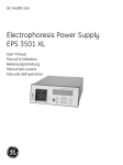
1
GE Healthcare Electrophoresis Power Supply EPS 3501 XL Operating Instructions Original instructions Table of Contents Table of Contents 1 Introduction .............................................................................. 5 1.1 1.2 1.3 2 Safety instructions................................................................. 15 2.1 2.2 2.3 2.4 2.5 3 7 Operation overview .............................................................................................. 27 Starting the instrument ...................................................................................... 27 Setting up a run ..................................................................................................... 28 Preparations before start .................................................................................. 35 Performing a run ................................................................................................... 35 Maintenance ........................................................................... 41 5.1 6 Site requirements .................................................................................................. 23 Unpacking ................................................................................................................. 23 Transport ................................................................................................................... 23 Connections ............................................................................................................. 24 Spare parts and accessories ........................................................................... 25 Operation ................................................................................ 27 4.1 4.2 4.3 4.4 4.5 5 Safety precautions ............................................................................................... 15 Labels .......................................................................................................................... 18 Emergency procedures ...................................................................................... 20 Built-in safety features ....................................................................................... 20 Recycling information ......................................................................................... 21 Installation .............................................................................. 23 3.1 3.2 3.3 3.4 3.5 4 Important user information ................................................................................. 5 Regulatory information ......................................................................................... 7 Instrument ................................................................................................................... 9 General ....................................................................................................................... 41 Troubleshooting ..................................................................... 43 Reference information .......................................................... 45 7.1 7.2 7.3 Specifications .......................................................................................................... 45 Literature ................................................................................................................... 45 Ordering information ........................................................................................... 45 Appendix A Electrical and communication connections...... 47 Electrophoresis Power Supply EPS 3501 XL Operating Instructions 28-9639-69 AA 3 Table of Contents 4 Electrophoresis Power Supply EPS 3501 XL Operating Instructions 28-9639-69 AA Introduction 1 Important user information 1.1 1 Introduction Purpose of the Operating Instructions The Operating Instructions provide you with the instructions needed to handle Electrophoresis Power Supply EPS 3501 XL in a safe way. Prerequisites In order to operate EPS 3501 XL safely and according to the intended purpose the following prerequisites must be met: • You should be acquainted with the use of general laboratory equipment and with handling of biological materials. • You should understand the concepts of electrophoresis. • You must read the Safety Instructions in Chapter 2 of these Operating Instructions. • The system should be installed according to the instructions in Chapter 3 of these Operating Instructions. In this chapter This chapter contains important user information and a general description of EPS 3501 XL and its intended use. 1.1 Important user information Read this before using EPS 3501 XL All users must read the Safety Instructions in Chapter 2 of these Operating Instructions before installing, using or maintaining the instrument. Do not operate EPS 3501 XL in any other way than described in the user documentation. If you do, you may be exposed to hazards that can lead to personal injury and you may cause damage to the equipment. Electrophoresis Power Supply EPS 3501 XL Operating Instructions 28-9639-69 AA 5 1 1.1 Introduction Important user information Intended use EPS 3501 XL is a high quality, high precision power supply for electrophoresis applications that require advanced programming and high voltage. EPS 3501 XL is intended for research use only, and shall not be used in any clinical procedures, or for diagnostic purposes. Safety notices These Operating Instructions contain WARNINGS, CAUTIONS and NOTICES concerning the use of the product, with meanings as defined below. WARNING WARNING indicates a hazardous situation which, if not avoided, could result in death or serious injury. It is important not to proceed until all stated conditions are met and clearly understood. CAUTION CAUTION indicates a hazardous situation which, if not avoided, could result in minor or moderate injury. It is important not to proceed until all stated conditions are met and clearly understood. NOTICE NOTICE indicates instructions that must be followed to avoid damage to the product or other equipment. 6 Electrophoresis Power Supply EPS 3501 XL Operating Instructions 28-9639-69 AA Introduction 1 Regulatory information 1.2 Notes and tips Note: A Note is used to indicate information that is important for trouble-free and optimal use of the product. Tip: A tip contains useful information that can improve or optimize your procedures. Typographical conventions Software texts and commands are identified by bold italic text. A colon is used to separate menu levels (e.g. File:Open refers to the Open option in the File menu). 1.2 Regulatory information This section lists the directives and standards that are fulfilled by EPS 3501 XL. Manufacturing information Requirement Content Name and address of manufacturer GE Healthcare Bio-Sciences AB, Björkgatan 30, SE 751 84 Uppsala Sweden Name and ID of notified body INTERTEK SEMKO AB, NB 0413 Place and date of declaration Uppsala, Sweden, May 2009 Identity of person authorized to sign DoC See EC Declaration of Conformity CE Conformity Directive Title 2006/42/EC Machinery Directive (MD) 2006/95/EC Low Voltage Directive (LVD) 2004/108/EC ElectroMagnetic Compatibility (EMC) Directive Electrophoresis Power Supply EPS 3501 XL Operating Instructions 28-9639-69 AA 7 1 1.2 Introduction Regulatory information International standards Standard Description Notes EN 61010-1, IEC 61010-1, CAN/CSA-C22.2 No. 61010-1 Safety requirements for electrical equipment for measurement, control and laboratory use EN 61326-1 EMC emissions and immunity requirements for electrical equipment measurement, control and laboratory use Harmonized with 2004/108/EC EN-ISO 12100-1, 12100-2 Safety of machinery – Basic concepts, general principles and design Harmonized with 2006/42/EC EN-ISO 14121-1, 14121-2 Safety of machinery – Principles of risk assessment Harmonized with 2006/42/EC CE marking The CE marking and the corresponding Declaration of Conformity is valid for the instrument when it is: • used as a stand-alone unit, or • connected to other CE-marked instruments, or • connected to other products recommended or described in the user documentation, and • used in the same state as it was delivered from GE Healthcare, except for alterations described in the user documentation or explicitly authorized by GE Healthcare. Regulatory compliance of connected equipment Any equipment connected to EPS 3501 XL should meet the safety requirements of EN 61010-1/IEC61010-1 or relevant harmonized standards. Within the European Union, connected equipment must be CE-marked. 8 Electrophoresis Power Supply EPS 3501 XL Operating Instructions 28-9639-69 AA Introduction 1 Instrument 1.3 1.3 Instrument This chapter contains a general description of EPS 3501 XL. General description EPS 3501 XL is a high quality, high precision power supply for electrophoresis applications that require advanced programming and high voltage. EPS 3501 XL is primarily designed for techniques using programming in several phases and/or voltage gradients: • 2-D (Two dimensional) electrophoresis using Multiphor II Electrophoresis System • IEF (Isoelectric focusing) using Immobiline™ or carrier ampholytes such as CleanGel™ and ExcelGel™ • Flatbed SDS-PAGE (Polyacrylamide Gel Electrophoresis) or flatbed native PAGE EPS 3501 XL is also suitable for: • DNA sequencing • Agarose electrophoresis • Electroblotting • DNA pulsed field electrophoresis Nine programs each with up to nine phases can be saved. Limiting values for voltage, current and power as well as voltage gradients can be programmed for precise control of the electrophoresis. The EPS 3501 XL automatically switches over the controlling parameter according to programmed limits and gradients and conductivity variations in the system. Two electrophoresis units can be connected to EPS 3501 XL and run with the same programmed method at one time. Electrophoresis Power Supply EPS 3501 XL Operating Instructions 28-9639-69 AA 9 1 1.3 Introduction Instrument Instrument description 1 2 3 Figure 1-1. The main parts of the EPS 3501 XL instrument. Part 10 Description 1 Display 2 Keyboard 3 Output sockets Electrophoresis Power Supply EPS 3501 XL Operating Instructions 28-9639-69 AA Introduction 1 Instrument 1.3 Indicator and switch on the instrument unit Indicator/Switch Color Description HV ON (indicator lamp) Green The HV ON lamp indicates that the high voltage power supply is on. Power (switch) - Switches on/off power to the instrument. Located on the rear panel. delete pa HV on con ST OP I 0 MAINS Disconnect before serv Front panel The front panel consists of an alphanumeric display, a keyboard with 9 membrane keys, a light emitting diode (LED) that lights when voltage is applied (HV on) and connectors for two electrophoresis units. Display 1 2 Part Description 8 7 6 5 4 3 Part Description 1 Mode 5 Breakpoint parameter 2 Voltage 6 Phase number 3 Current 7 Control mode (step) 4 Power 8 Program number Electrophoresis Power Supply EPS 3501 XL Operating Instructions 28-9639-69 AA 11 1 1.3 Introduction Instrument Keyboard Key Label Description set enter Press set enter to enter a value or choice, confirm this if valid, and move programming to the next field. Valid values are voltage 35–3 500 V, current 1–400 mA, power 1–200 W, time 0:01–500 h, volthours 1–500 000 Vh, milliampere-hours 1–25 000 mAh. set enter In the RUN mode, pressing set enter shows the programmed parameters for the actual run. In addition, set enter allows you to make changes in the program during a run after first pressing pause continue. After a run, when in END mode, pressing set enter puts the instrument into SET, its programming mode. run pause - Press to change the parameter, value or other choice in the field which is blinking. Numerical values are changed in an accelerating manner when a key is held down. Clicking a key changes the value in preset increments. Parameters or units (e.g. Vh) and choices (e.g. Yes/No) are changed with one key push. The keys can also be used to switch between time and volthours in RUN, PAUSE and END. The values scroll i.e. they automatically change from maximum to minimum value or vice versa. run Press run to start the run and put the program into RUN mode. The current values for voltage, current and power are shown on the display. The elapsed time, volthours or milliamperehours are also displayed. Switch between these last three parameters with pause continue Press pause continue to put the instrument in PAUSE mode and switch off the voltage. The display shows the status of the run at the time the key was pressed. pause continue only operates in RUN mode. Time, integrated voltage and integrated current are retained. continue In the PAUSE MODE mode, set enter can be used to make changes in the program. Return to RUN mode by pressing pause continue or by pressing run. STOP 12 STOP Press STOP to stop the run and put the instrument in END mode. The voltage is switched off and the end parameters are displayed. Switch between time, integrated voltage and integrated current by pressing . A run cannot be continued after pressing STOP. Press run to run the same method again or press set enter to choose another program, program a new method or make changes in an existing method. Electrophoresis Power Supply EPS 3501 XL Operating Instructions 28-9639-69 AA Introduction 1 Instrument 1.3 Key Insert Label Description insert delete Press insert delete to insert or delete a phase in a program. This function is activated in SET mode. Note that a program must be completed by answering Yes (Y) to the question “Last Phase?” in SET mode or by pressing exit before you can use the insert delete key. more Press more to place program in MORE mode. This gives access to some special functions. These include: delete more COPY: Copying a program. CLEAR: Clearing a program. SETUP: Disabling the start current check. MORE mode cannot be activated in RUN or PAUSE mode. Leave MORE by pressing exit. exit exit Press exit to stop the execution of an operation, such as the entry of a value. Only values/units that have already been confirmed by set enter are retained when exit is pressed. Note that if a phase contains zeros when pressing exit, that phase will be deleted. Press exit to return the instrument to the mode that was left or to the start position in SET. Output sockets There are two sets of output sockets to allow two electrophoresis units to be connected and run at the same time. + - Output socket Label Color Voltage Positive + Red 0 and +1750 V Negative - Black or blue 0 and –1750 V Electrophoresis Power Supply EPS 3501 XL Operating Instructions 28-9639-69 AA 13 1 1.3 14 Introduction Instrument Electrophoresis Power Supply EPS 3501 XL Operating Instructions 28-9639-69 AA Safety instructions 2 Safety precautions 2.1 2 Safety instructions This chapter describes safety compliance, safety labels, general safety precautions, emergency procedures, power failure and recycling of EPS 3501 XL. 2.1 Safety precautions Introduction The EPS 3501 XL is powered by mains voltage and handles liquids that may be hazardous. Before installing, operating or maintaining the equipment, you must be aware of the hazards described in this manual. Follow the instructions provided to avoid personal injury or damage to the equipment. The safety precautions in this section are grouped into the following categories: • General precautions • Personal protection • Installing and moving the instrument • System operation • Maintenance General precautions WARNING Do not operate the EPS 3501 XL in any other way than described in the EPS 3501 XL User Manual. WARNING Operation and user maintenance of EPS 3501 XL should be performed by properly trained personnel only. WARNING Do not use any accessories not supplied or recommended by GE Healthcare. Electrophoresis Power Supply EPS 3501 XL Operating Instructions 28-9639-69 AA 15 2 2.1 Safety instructions Safety precautions WARNING Do not use EPS 3501 XL if it is not working properly, nor if it have suffered any damage, for example: • damage to the power cord or its plug • damage caused by dropping the equipment • damage caused by splashing liquid onto items not supplied or recommended by GE Healthcare. WARNING Operation and user maintenance of EPS 3501 XL should be performed by properly trained personnel only. WARNING EPS 3501 XL is a high voltage instrument that can cause fatal electrical shock if the safety features are disabled. The safety lid must be securely closed before starting a protocol. WARNING The instrument covers must not be opened by the user. It contains electrical circuits which can give a lethal electric shock. Service and planned maintenance should be performed by personnel authorized by GE Healthcare. Personal protection WARNING Always use appropriate personal protective equipment during operation and maintenance of EPS 3501 XL. Installing and moving the instrument WARNING Supply voltage. Make sure that the supply voltage at the wall outlet corresponds to the marking on the instrument, before connecting the power cord. 16 Electrophoresis Power Supply EPS 3501 XL Operating Instructions 28-9639-69 AA Safety instructions 2 Safety precautions 2.1 WARNING Protective ground. The EPS 3501 XL must always be connected to a grounded power outlet. WARNING Power cord. Only use power cords delivered or approved by GE Healthcare. WARNING Access to power switch and power cord. Do not block the rear panel of the instrument. The Power switch must always be easy to access. The power cord must always be easy to disconnect. System operation WARNING Hazardous biological agents during run. When using hazardous biological agents, flush the entire system tubing with bacteriostatic solution followed by a neutral buffer and finally distilled water, before service and maintenance. WARNING Avoid spilling liquids on the body of the instrument. If large volumes of liquid have penetrated the casing of the instrument and come into contact with the electrical components, immediately switch off the instrument and contact an authorized service technician. Maintenance WARNING Do not remove the main cover. There are no user serviceable components inside, and you can be exposed to high voltage. Electrophoresis Power Supply EPS 3501 XL Operating Instructions 28-9639-69 AA 17 2 2.2 Safety instructions Labels 2.2 Labels This section describes the safety labels and labels concerning hazardous substances that are attached to EPS 3501 XL. Labels on the instrument Rear panel labels The illustration below shows an example of the identification label that is attached to EPS 3501 XL. XX-XXXX-XX 28-9269-30 EPS 3501 XL 3 ETTAN IPGphor Code No: XXXXXXXX Voltage: Code No: 11003364 Voltage: 100-240 V Frequency: Serial No XXXXXXX Serial No: 1234567 Frequency: 50-60 Hz Mfg Year: 2009 Power max: Mfg Year: 2009 Power max: 230 VA Fuse: Fuse: 2x T2.5AL 250 V N12406 N12406 Made in Sweden GE Healthcare Bio-Sciences AB Made in Sweden GE Healthcare Bio-Sciences AB 751 84 Uppsala Sweden 751 84 Uppsala Sweden 28952336aa 28952336aa Front panel labels Symbols used in safety labels Label Meaning Warning! Read the user documentation before using the system. Do not open any covers or replace parts unless specifically stated in the user documentation. 18 Electrophoresis Power Supply EPS 3501 XL Operating Instructions 28-9639-69 AA Safety instructions 2 Labels 2.2 Label Meaning Indicates that hazardous voltages are generated inside the instrument. The system complies with the requirements for electromagnetic compliance (EMC) in Australia and New Zealand. The system complies with applicable European directives. Labels concerning hazardous substances Label Meaning This symbol indicates that the waste of electrical and electronic equipment must not be disposed as unsorted municipal waste and must be collected separately. Please contact an authorized representative of the manufacturer for information concerning the decommissioning of equipment. This symbol indicates that the product contains hazardous materials in excess of the limits established by the Chinese standard SJ/ T11363-2006 Requirements for Concentration Limits for Certain Hazardous Substances in Electronics. Electrophoresis Power Supply EPS 3501 XL Operating Instructions 28-9639-69 AA 19 2 2.3 Safety instructions Emergency procedures 2.3 Emergency procedures This section describes how to do an emergency shutdown of EPS 3501 XL. The section also describes the result in the event of power failure. Emergency procedures In an emergency situation, do as follows to stop the run: Step Action 1 Switch off power to the instrument by pressing the Power switch to the 0 position. If required, disconnect the mains power cord. The run is interrupted immediately. Power failure The result of a power failure depends on which unit that is affected. Power failure to... will result in... EPS 3501 XL The run is interrupted immediately, in an undefined state 2.4 Built-in safety features The power supply has the following built-in safety functions: Function Description Functional earth leakage Should the power supply be connected to an electrophoresis unit that has a leakage path to earth, the EPS 3501 XL will detect this fault and turn off the high voltage. Start current check The power supply checks that the resistance is not higher than a specified limit at a low safety voltage (<40V). If this resistance is too high, the high voltage is turned off. Too high resistance can be caused by for example: - an electrophoresis unit incorrectly connected - use of buffer with exremely low conductivity This function can be disabled to perform certain applications, see Electrophoresis Power Supply EPS 3501 XL User Manual. 20 Electrophoresis Power Supply EPS 3501 XL Operating Instructions 28-9639-69 AA Safety instructions 2 Recycling information 2.5 Function Description Sudden load change detection This function prevents accidents under running conditions due to a break in the electrical circuit such as a bad connection to the electrophoresis unit. The high voltage is turned off in such an event. An error messages is shown on the display in the event of a sudden load change. 2.5 Recycling information The equipment shall be decontaminated before decommissioning and all local regulations shall be followed with regard to scrapping of the equipment. Disposal, general instructions When taking EPS 3501 XL out of service, the different materials must be separated and recycled according to national and local environmental regulations. Recycling of hazardous substances EPS 3501 XL contains hazardous substances. Detailed information is available from your GE Healthcare representative. Disposal of electrical components Waste of electrical and electronic equipment must not be disposed as unsorted municipal waste and must be collected separately. Please contact an authorized representative of the manufacturer for information concerning the decommissioning of equipment. Electrophoresis Power Supply EPS 3501 XL Operating Instructions 28-9639-69 AA 21 2 2.5 22 Safety instructions Recycling information Electrophoresis Power Supply EPS 3501 XL Operating Instructions 28-9639-69 AA Installation 3 Site requirements 3.1 3 Installation EPS 3501 XL is delivered in protective packing material and shall be unpacked with great care. Any equipment connected to EPS 3501 XL must fulfill applicable standards and local regulations. For detailed information on Installation, see Electrophoresis Power Supply EPS 3501 XL User Manual. 3.1 3.2 Site requirements Parameter Requirement Electrical power 100-240 V, 50-60 Hz Ambient temperature 4°C to 40°C Placement Stable laboratory bench Humidity 0 to 95 %, non-condensing Unpacking • Check the equipment for damage before starting assembly and installation. • Document any damage and contact your local GE Healthcare representative. Remove straps and packing material and stand equipment upright before starting installation. 3.3 Transport Before moving the system: disconnect all connected cables. Electrophoresis Power Supply EPS 3501 XL Operating Instructions 28-9639-69 AA 23 3 Installation 3.4 3.4 Connections Connections Communication Connect EPS 3501 XL according to the electrical drawings in Appendix A. Connect the leads from the electrophoresis unit to the output sockets on the EPS 3501 XL front panel (red to red, and black or blue to blue), see Section 1.3. The red lead is the positive and black or blue is the negative. + - Electrical power Connect the power cord to a grounded power outlet specified in Section 3.1. Select the appropriate voltage range, 100–120 or 220–240 V, using the switch on the rear panel. NOTICE If the power supply is connected to 220-240 V with the range set to 100– 120 V, the instrument can be severely damaged. Local regulation for Great Britain This appliance must be earthed. The wires in the mains lead are colored in accordance with the following code: Color Meaning Green and yellow Earth Blue Neutral Brown Live If the plug provided is unsuitable for your socket outlets, the plug must be cut off and suitable plug fitted. The cut-off plug should be disposed of and must not be inserted into any 13 amp socket as this can result in electric shock. The plug or adapter of the distribution panel should be provided with 13 amps fuse. As the colors of the wires in the mains lead of this appliance may not correspond with colored markings identifying the terminals in your plug, proceed as follows: 24 Electrophoresis Power Supply EPS 3501 XL Operating Instructions 28-9639-69 AA Installation 3 Spare parts and accessories 3.5 • The green and yellow wire must be connected to the terminal in the plug which is marked with the letter E or by the earth symbol, or colored green, or green and yellow. • The blue wire must be connected to the terminal which is marked with the letter N or colored black. • The brown wire must be connected to the terminal which is marked with the letter L or colored red. Note: After replacing or changing a fuse, the fuse cover in the plug must be replaced with a fuse cover which corresponds to the colour of the insert in the base of the plug or the word that is embossed on the base of the plug, and the appliance must not be used without a fuse cover. Note: Only 13 Amps fuse approved to B.S 1362 A.S.T.A. should be used. 3.5 Spare parts and accessories For correct up to date information on spare parts and accessories visit: www.gelifesciences.com\2DE Electrophoresis Power Supply EPS 3501 XL Operating Instructions 28-9639-69 AA 25 3 3.5 26 Installation Spare parts and accessories Electrophoresis Power Supply EPS 3501 XL Operating Instructions 28-9639-69 AA Operation 4 Operation overview 4.1 4 Operation 4.1 Operation overview The operation of the EPS 3501 XL is described in the following sequence. 1 Programming or editing a method. 2 Editing a method. 3 Running a method. Programming and running are discussed in more detail in the following sections. Blinking characters in the display are shown as bold characters in this manual. 4.2 Starting the instrument Turn on the instrument by pressing the Power switch to the I position. When the power supply is turned on, the display shows the start position in SET mode. The previous program set is shown and that program number is blinking. SET: 0V 1 1 0mA 0:00h 0W If the power supply is turned on for the first time or if the program has been cleared, (see Optional programming‚ on page 34) the default way of controlling is step ( ), the breakpoint parameter is time (h), the alarm is off and the values are all zero. Electrophoresis Power Supply EPS 3501 XL Operating Instructions 28-9639-69 AA 27 4 4.3 Operation Setting up a run 4.3 Setting up a run Programming a method Choosing a program Up to nine programs, each with up to nine phases, can be entered. Press set enter to confirm the program shown by the number on the display or use keys to choose another. Confirm with set enter. 1 1⁄1 1 mA SET: 500 V Select by 2 Confirm by Confirm by SET: 0V Confirm by 4 SET: 0V 2 1 0 mA 0:00 h 0W 2 1 0 mA 0:00 h 0W SET: 1000 V Confirm by 2 1 10 mA 2 1 10 mA SET: 1000 V 8 SET: 1000 V SET: Last phase 2 1 10 mA 28 set enter Breakpoint OFF set enter SET: 1000 V 0 Vh 10 W Confirm by set enter 1000 Vh Y 2 1 ? Confirm by set enter Yes No Alarm Phase 1? Phase: - - - - Select by 11 enter Vh Select by 10 set 0:00 h 10 W Confirm by Select by 9 enter Other phases 2 1 10 mA Select by set 0:00 h 0W Confirm by 1st Phase SET: 1000 V enter 0:00 h 0W Confirm by Select by 7 set enter Select by 6 enter set Select by 5 set 2 1 SET STEP/gradient Select by 3 1 Vh 5W N Confirm by 2 1A 10 mA 1000 Vh 10 W set enter SET: 1000 V 2 1A 10 mA 1000 Vh 10 W Electrophoresis Power Supply EPS 3501 XL Operating Instructions 28-9639-69 AA Operation 4 Setting up a run 4.3 Step Action Selection 1 Choose Program number. 2 2 Choose STEP or GRADIENT mode. STEP 3 Confirm Phase number. 1 4 Set Voltage limit (in Step mode) or Voltage endpoint 1000 V 1 (in Gradient mode). 1 5 Set Current limit. 10 mA 6 Set Power limit. 10 W 7 Choose Breakpoint unit (h, Vh or mAh) or no breakpoint (OFF). Vh, OFF 8 Set Breakpoint 1000 Vh 9 Is this the last phase (Last Phase ?)? Choose Yes (Y) or No (N)? 10 Choose Alarm Off (N) or On (Y). 11 The program is ready. Y Selection made in this example. Figure 4-1. Step-by-step summary of programming. Choosing step or gradient programming Press set enter to confirm STEP ( ) or use with set enter. keys to choose GRADIENT (/). Confirm Note that your choice of gradient or step programming applies for all phases within the program and you will only be asked to choose one of them when programming the first phase. Choosing step means that voltage, current and power limiting values are programmed. The electrophoresis will be controlled by one of these limiting values, which means that it is run at either constant voltage, current or power. The EPS 3501 XL automatically switches over the controlling parameter according to programmed limits and conductivity variations in the system. Thus the controlling parameter can switch within a phase. Electrophoresis Power Supply EPS 3501 XL Operating Instructions 28-9639-69 AA 29 4 4.3 Operation Setting up a run Table 4-1 and Figure 4-2 illustrate a step program. The programming and running of this application are shown as Figure 4-1 and Figure 4-5. E 3500 D 1500 Vh C 2000 1000 Vh A 1000 B 1000 Vh 500 120 Vh 1 No. Description 2 No. F Description A Phase 1 D Phase 4 B Phase 2 E Voltage (V) C Phase 3 F Time (h) Figure 4-2. Programming the voltage limiting profile in STEP mode. The parameters shown are the same as those listed in Table 4-1. Table 4-1. The parameters of a step program. Phase number Voltage (V) Current (mA) Power (W) Volthours (Vh) 1 1000 10 10 1000 2 500 10 5 120 3 2000 20 15 1000 4 3500 30 25 1500 Choosing gradient ( ), means that a voltage endpoint for the actual phase is programmed together with current and power limiting values. A linear voltage gradient is made with zero (for the first phase) or the programmed endpoint of the phase before (for the next phases) as starting point and the programmed endpoint as 30 Electrophoresis Power Supply EPS 3501 XL Operating Instructions 28-9639-69 AA Operation 4 Setting up a run 4.3 endpoint. The electrophoresis will be controlled by this voltage gradient provided the limiting current or power is not attained. The EPS 3501 XL thus automatically switches over the controlling parameter according to the programmed limits and conductivity variations in the system. E 3500 3 4 D 33250 Vh A C 1 Vh B 500 1 10000 Vh 2 2500 Vh 5 10 19.5 F No. Description No. Description A Phase 1 D Phase 4 B Phase 2 E Voltage (V) C Phase 3 F Time (h) Figure 4-3. Programming the voltage limiting profile in GRADIENT mode. The parameters shown are the same as those listed in Table 4-2. To illustrate voltage gradient programming, the programming for the IEF part of a 2-D electrophoresis with Immobiline™ DryStrip Gels is shown in Table 4-2 and Figure 4-3. Note that the first phase is a very steep gradient to reach the 500 V start level (0–500 V, within 1 Vh). The next phase is actually a step since the endpoint for phase 2 is 500 V which is the same as the endpoint for phase 1. Phase 3 is the “real” gradient, the voltage is changed from 500 to 3500 V in 5 hours. The last phase is a step again, the endpoint voltage is the same as for the phase before and the voltage will remain on 3500 V for 9.5 hours. Electrophoresis Power Supply EPS 3501 XL Operating Instructions 28-9639-69 AA 31 4 4.3 Operation Setting up a run Table 4-2. The parameters of a gradient program. Phase number Voltage (V) Current (mA) Power (W) Volthours (Vh) 1 500 1 5 0:01 2 500 1 5 5 2500 3 3500 1 5 5 10000 4 3500 1 5 9.5 33250 1 1 1 1 The ramping from 0 to 500 V should be done as quickly as possible. The smallest possible time that can be set is 1 minute and the smallest possible Vh that can be set is 1 Vh. Vh was chosen for this program as breakpoint unit. Choose phase number Choose phase number with and confirm with set enter. For a new program the default phase number is 1. If the first phase has been programmed and the question “Last phase ?“ is answered by No (N), the default number is 2 and so on. Setting voltage, current and power The display will now flash for the set voltage limit (STEP mode) or voltage endpoint (GRADIENT mode). Using the keys, select the voltage limit or voltage endpoint desired for the run. Confirm with set enter. Repeat the same procedure for limiting current and limiting power. Programmable values for voltage are 35-3500 V; current, 1-400 mA; power, 1-200 W. Setting breakpoint Choose between automatic or manual break. For automatic break, choose breakpoint unit in either hours (h), volthours (Vh) or milliamperehours (mAh). Select the correct unit or, for manual break, choose ”OFF” with . Confirm with set enter. Note that the breakpoint unit is valid for all phases within the program and you will only get this question when programming the first phase, see “Other phases” bypass in Figure 4-1. If h, Vh or mAh is chosen, the display will flash for the break value for the actual phase. Set the value with and confirm with set enter. Programmable values for time are 0:01-500 h, volthours, 1-500 000 Vh, milliamperehours, 1-25 000 mAh. If OFF is chosen, you have to break the electrophoresis manually by pressing STOP and only one phase can be entered. The program will go back to the start position and the program number will flash. Last Phase? After programming the breakpoint you are asked if this is the last phase or not. Select Yes (Y) or No (N) with and confirm with set enter. 32 Electrophoresis Power Supply EPS 3501 XL Operating Instructions 28-9639-69 AA Operation 4 Setting up a run 4.3 If Y is selected, no more phases will be added and the alarm question will be shown, see below. If N is selected, the next phase number for the program will be shown on the display together with zero values for all parameters. Program the next phase according to Setting voltage, current and power‚ on page 32 and Figure 4-1 step 4. Up to nine phases can be programmed. Choosing alarm The alarm can be set separately for each phase. The following question is shown: Alarm Phase 1? Select Yes (Y) or No (N) with and confirm with set enter. If Y is selected in a 4 phase program this will be indicated by changing from - - - to 1 - - - after “Phase” on the lower row in the display. Then you will be asked about an alarm for the next phase. After answering Y or N for the last phase, the start position in the SET mode will be shown. If alarm is selected for a phase a small “A” appears on the A right of the phase number, i.e. 2 2 . Back to start position The program is now back to the start position in the SET mode with the program number flashing. It is possible to go back to this position at any stage during programming in SET mode by pressing exit or STOP. Note that the program is automatically saved with all choices that have been confirmed by set enter when exit or STOP is pressed. If a phase containing invalid values (zeros) is left, this phase will be deleted. Disabling the start current check See Optional programming‚ on page 34 if you want to use this feature. Editing a program Changing a parameter value To change a parameter value, move to the start position in SET mode by pressing exit or set enter and choose program number as described in Choosing a program‚ on page 28. If the programming mode (step or gradient) is changed it will be changed for all the phases within the program. Select phase number by be changed. Change with and move in the program with set enter to the value to and confirm with set enter. Press exit. Inserting and deleting a phase Inserting and deleting a phase is described schematically in Figure 4-4. Note that you must first enter a phase before it can be inserted or deleted: 1 If needed, change program number by entering the start position in SET mode with set enter or exit, changing the number with and confirming by set enter. 2 Bypass the mode question with set enter. Electrophoresis Power Supply EPS 3501 XL Operating Instructions 28-9639-69 AA 33 4 4.3 Operation Setting up a run 3 Change to the desired phase number by and confirm with set enter. Choose to delete the phase shown on the display or insert a new phase with this phase number by pressing and confirm with set enter. If Delete is chosen, the selected phase will be deleted and the program will move back to the position with the phase number blinking. Note that by deleting a phase, the numbers of the following phases will decrease by 1. If Insert is chosen, the program will enter the same position and the new phase can be programmed as a new phase (see Programming a method‚ on page 28 and Figure 4-1, steps 4-8). After entering the breakpoint, the question “Last Phase?”will be bypassed and the starting point for the next phase will be entered. Note that by inserting a new phase the number for the old phase with that number and the numbers for the following phases will increase by 1. Adding a phase after the last phase is done by entering the last phase as above, moving to the question “Last Phase?” and answering No (N). The program will jump to the start position for programming a phase with the phase number blinking. Proceed with programming as described for a new program. It is not possible to insert or delete a phase for a running program. Editing a running program See Section 4.5. Copying and clearing a program See Optional programming‚ on page 34. Optional programming MORE mode contains three special functions: • COPY: Copying a program. • CLEAR: Clearing a program. • SETUP: Disabling the start current check. For more information regarding these functions, refer to Electrophoresis Power Supply EPS 3501 XL User Manual. Choosing run parameters EPS 3501 XL is an automatic cross-over power supply that allows the user to set limits for voltage, current and power. It is also possible to program linear voltage gradients. During electrophoresis, only one of the parameters is limiting at a time. The limiting parameter determines, together with the conductivity in the electrophoresis system, the values for the other two parameters. For information about selecting parameter values, refer to Electrophoresis Power Supply EPS 3501 XL User Manual. 34 Electrophoresis Power Supply EPS 3501 XL Operating Instructions 28-9639-69 AA Operation 4 Preparations before start 4.4 4.4 Preparations before start Connect the leads from the electrophoresis unit (red to red, and black or blue to blue). Red is positive and black or blue negative. Up to two electrophoresis units can run at the same voltage at one time. Remember to double the maximum current and power conditions if two units are to be run. Voltage will be the same regardless of the number of units. The current should also be doubled if two gels are run on the same unit. 4.5 Performing a run Running a program is described schematically in Figure 4-5. Choosing a program Press set enter and select the program you wish to run by pressing until the value is correct. (Omit this step if you have just programmed or edited a method as described in Programming a method‚ on page 28 and Editing a program‚ on page 33.) Running Press run to start the electrophoresis. Information about the status of the start current check will be displayed for a few seconds. The display will then show current values for voltage, current and power and one of elapsed time, volthours or milliamperehours. You can switch between showing the elapsed time, volthours or milliamperehours by . The parameter controlling the electrophoresis is underlined. A light emitting diode shows when voltage is applied (HV on). If no current is displayed or if “HALT: Low start current” is shown, check the electrical connections to the electrophoresis equipment. Electrophoresis Power Supply EPS 3501 XL Operating Instructions 28-9639-69 AA 35 4 4.5 Operation Performing a run 1 1 ⁄ 1A 1 mA SET: 500 V Confirm by Select by 2 1 Vh 5W set enter SET: 2 1 step/GRADIENT Confirm by 3 SET: 1000 V Select by 4 Insert INS/del Select by set enter 2 1 120 mA 1000 Vh 10 W Enter by SET: 0V 2 2 0 mA delete Phase 2 Confirm by Insert 5a Insert 00:00 h 0W set enter Delete SET: 2000 V 2 2 20 mA 1000 Vh 15 W 5b Programming point 4 Step Action 1 Choose Program number. 2 Choose STEP or GRADIENT mode. 3 Choose Phase number. Press Insert delete. 4 Choose Insert or Delete. 5a Program a new phase 2. 5b Back to new Phase 2 start position. Old phase 2 is deleted. Figure 4-4. Inserting and deleting a phase in a program. 36 Electrophoresis Power Supply EPS 3501 XL Operating Instructions 28-9639-69 AA Operation 4 Performing a run 4.5 Pausing You can interrupt the electrophoresis for sample loading and/or changing the program by pressing pause continue. Voltage will no longer be supplied, the HV on LED goes off, and you may safely load your samples. The display shows the status of the run when pause continue was pressed. Switch between time, integrated voltage and integrated current for the phase running when pause continue was pressed with . When sample loading is complete, press either pause continue again or run to continue the run from where it was interrupted. Editing a running program when in PAUSE When in the PAUSE mode you can also press set enter to make changes in the program. This mode is called the P-SET mode. When the P-SET mode is entered you can make changes as described in Changing a parameter value‚ on page 33. It is not possible to insert or delete a phase for a running program. The P-SET mode is the same as the SET mode apart from restrictions in setting the breakpoint. Naturally, it is not possible to enter a time, integrated voltage or current that is already passed. Press exit or pause continue to go back from P-SET to PAUSE. Press run or pause continue to proceed with the electrophoresis. Electrophoresis Power Supply EPS 3501 XL Operating Instructions 28-9639-69 AA 37 4 4.5 Operation Performing a run 1 SET: 500V 1⁄1 1 mA 1 Vh 5W Select by 2 SET: 1000 V 2 1A 1000 Vh 10 mA 10 W Start by run RUN: 500 V 2 1A 5 Vh 10 mA 5 W RUN: 900 V 2 1A 1000 Vh 10 mA 9 W set pause enter SET: 1000 V 2 1A 10 mA 1000 Vh 10 W exit or wait 5 s continue pause continue 3 2 1A 25 mA PAUSE: 900 V 1000 Vh 9W run or pause set P-SET: 1000 V exit continue enter 2 1A 10 mA or 1000 Vh 10 W Programming STOP 4 RUN: 2500 V 2 ⁄ 4A 10 mA 880 Vh 25 W 5 END: 3125 V 2 ⁄ 4A 8 mA 3620 Vh 25 W Step END: 2500 V 2 ⁄ 4A 10 mA 3000 Vh 25 W Action 1 Choose Program number. 2 Start the run. 3 During a run you can view the settings. It is also possible to interrupt the run and make changes in the program. 4 Stop the run manually. 5 The run is stopped automatically. Figure 4-5. Running, viewing and pausing a program. View programmed values It is also possible to view the programmed values during a run by pressing set enter. Note that no values can be changed here. Only one phase is shown at one time. Switch to another phase by using . The display returns automatically to show RUN values after 5 s. Alternatively use exit or run. 38 Electrophoresis Power Supply EPS 3501 XL Operating Instructions 28-9639-69 AA Operation 4 Performing a run 4.5 Stopping the run and viewing end parameter values When the programmed time, volthours or milliamperehours for the last phase is attained, the program will enter the END mode. It is also possible to break the run manually by pressing STOP. In both cases, the voltage, current and power will go to zero as indicated by the HV on LED switching off. The end parameter values are displayed. Switch between total elapsed time, integrated voltage or integrated current for all phases in the program by . An alarm will sound at the end of each phase if selected in the program. You can stop the alarm after the last phase by pressing STOP. A run cannot be continued after pressing STOP. Disconnect the leads and proceed with post-electrophoretic techniques. Since diffusion will begin as soon as the voltage is turned off, you should remove the gel and begin staining, blotting or autoradiography immediately. Electrophoresis Power Supply EPS 3501 XL Operating Instructions 28-9639-69 AA 39 4 4.5 40 Operation Performing a run Electrophoresis Power Supply EPS 3501 XL Operating Instructions 28-9639-69 AA Maintenance 5 General 5.1 5 Maintenance 5.1 General No user maintenance is required for Electrophoresis Power Supply EPS 3501 XL. NOTICE Cleaning. Keep the instrument dry and clean. Wipe regularly with a soft damp tissue and, if necessary, a mild cleaning agent. Let the instrument dry completely before use. WARNING Electrical shock hazard. All repairs should be done by service personnel authorized by GE Healthcare. Do not open any covers or replace parts unless specifically stated in the user documentation. Electrophoresis Power Supply EPS 3501 XL Operating Instructions 28-9639-69 AA 41 5 5.1 42 Maintenance General Electrophoresis Power Supply EPS 3501 XL Operating Instructions 28-9639-69 AA Troubleshooting 6 6 Troubleshooting If an error that can be corrected by the user occurs, either during a run or when switching on the power supply, the program enters the HALT mode and the output is switched off. Four different types of errors can cause HALT. The following table shows the error message on the display, the cause and the actions necessary. Error message Cause Action The current is less than the lower limit. This can be due to incorrect connection of the electrophoresis equipment or due to use of buffers with extremely low conductivity. 1 Check connections and/or buffers. 2 Press more, switch off the start current check in the MORE mode. See Electrophoresis Power Supply EPS 3501 XL User Manual for more information. HALT: Ground leakage current The current to ground leakage in the electrophoresis unit is too high. Check the electrophoresis unit. HALT: Mains Voltage too low! The mains voltage is too low, refer to Electrophoresis Power Supply EPS 3501 XL User Manual . Check voltage selector. Mains power failure for more than 7 secs. Press pause continue to continue running a program or STOP to interrupt the run. HALT: Low start current! HALT: Mains fail Program stopped Check mains voltage If a serious error occurs, the program enters the FAIL mode. The output is switched off and an error message is shown in the display. FAIL:Code No: xxx Call service Please note the error code number and contact your GE Healthcare representative. Electrophoresis Power Supply EPS 3501 XL Operating Instructions 28-9639-69 AA 43 6 44 Troubleshooting Electrophoresis Power Supply EPS 3501 XL Operating Instructions 28-9639-69 AA Reference information 7 Specifications 7.1 7 7.1 7.2 Reference information Specifications Parameter Value Ingression protection IP20 Supply voltage 100-240 V ~, 50 to 60 Hz Power consumption Max 260 W Dimensions (H × W × D) 95 × 250 × 315 mm Weight 3.8 kg Ambient temperature +4 to +40 °C Relative humidity tolerance 0 to 95% Atmospheric pressure 84 to 106 kPa (840 to 1060 mbar) Acoustic noise level < 70 dB A Literature For further information regarding Electrophoresis Power Supply EPS 3501 XL, refer to the Electrophoresis Power Supply EPS 3501 XL User Manual. 7.3 Ordering information For ordering information visit www.gelifesciences.com/2DE. Electrophoresis Power Supply EPS 3501 XL Operating Instructions 28-9639-69 AA 45 7 7.3 46 Reference information Ordering information Electrophoresis Power Supply EPS 3501 XL Operating Instructions 28-9639-69 AA Electrical and communication connections Appendix A Appendix A Electrical and communication connections Voltage Frequency Power 100-120/220-240 VAC 50/60 Hz 260 W 4A Max I 0 MAINS Disconnect before servicing 100-120 1 2 Part Description 1 Power switch 2 Power inlet 3 Voltage range switch 220-240 3 Electrophoresis Power Supply EPS 3501 XL Operating Instructions 28-9639-69 AA 47 Appendix A 48 Electrical and communication connections Electrophoresis Power Supply EPS 3501 XL Operating Instructions 28-9639-69 AA For local office contact information, visit www.gelifesciences.com/contact GE Healthcare Bio-Sciences AB Björkgatan 30 751 84 Uppsala Sweden www.gelifesciences.com GE, imagination at work and GE monogram are trademarks of General Electric Company. CleanGel, ExcelGal and Immobiline are trademarks of GE Healthcare companies. All third party trademarks are the property of their respective owners. © 2009 General Electric Company—All rights reserved. First published Oct. 2009 All goods and services are sold subject to the terms and conditions of sale of the company within GE Healthcare which supplies them. A copy of these terms and conditions is available on request. Contact your local GE Healthcare representative for the most current information. GE Healthcare UK Ltd Amersham Place, Little Chalfont, Buckinghamshire, HP7 9NA, UK GE Healthcare Bio-Sciences Corp 800 Centennial Avenue, P.O. Box 1327, Piscataway, NJ 08855-1327, USA GE Healthcare Europe GmbH Munzinger Strasse 5, D-79111 Freiburg, Germany GE Healthcare Japan Corporation Sanken Bldg. 3-25-1, Hyakunincho, Shinjuku-ku, Tokyo 169-0073, Japan imagination at work 28-9639-69 AA 10/2009