1
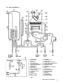
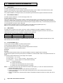
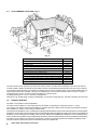
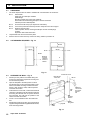
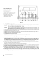
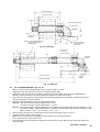
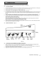
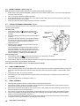
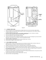
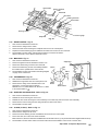
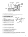
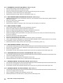
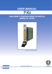
5
COMMISSIONING
When commissioning the boiler, ensure the Benchmark Log Book is completed.
5.1
FILL THE SYSTEM
1.
The boiler is fitted with an automatic air vent positioned on the pump (see Fig. 2). The vent is fitted with a non-sealing cap.
2.
Open the central heating flow and return valves (spindle flats in-line with valve) (see Fig. 13).
3.
Open the fill point valve on the filling loop until water is heard to flow.
4.
To remove the air - Vent each radiator in turn, starting with the lowest in the system.
5.
It is important that the pump is properly vented to avoid it running dry and damaging its bearings. Unscrew and remove the
cap from the centre of the pump. Using a suitable screwdriver rotate the exposed spindle about half a turn, then replace
the cap.
6.
Check the operation of the heating pressure relief valve (see Fig. 2) by turning the head anti-clockwise until it clicks. The
click is the valve lifting off its seat allowing water to escape from the system - check that this is actually happening.
7.
Continue to fill the system until the pressure gauge indicates 1.0 bar. Close the fill point valve and check the system for
water soundness, rectifying where necessary.
Disconnect the filling loop from the mains supply.
Water may be released from the system by manually venting a radiator until the system design pressure is obtained.
The system design pressure (cold) should be between 0.75 and 1.25 bar.
Refer to sections 3.7 and 3.8. System volume and Filling the system.
8.
Open the mains water supply valve and allow the storage cylinder in the boiler to fill. Turn on all hot water taps and allow
water to flow until no air is present. Turn off taps.
5.2
BOILER CONTROLS - Fig. 18
Burner
Viewing
Window
0 THERMOSTAT
0 THERMOSTAT
Clock
(if fitted)
RESET
0 SELECTOR
2
3
1
0
bar
4
RESET
Central
Heating
Thermostat
Domestic
Hot Water
Thermostat
Selector Indicator
Neons
Switch
White
Reset
Button
Red
Reset
Button
System
Pressure
Gauge
Fig. 18
5.3
TEST FOR GAS SOUNDNESS AND PURGE THE SUPPLY
1.
With the boiler gas service cock closed (spindle flats at right angles to valve). Pressure test the gas supply and inlet
pipework connection to the boiler gas service cock for soundness in accordance with BS 6891.
2.
Loosen the gas inlet pressure test point screw on the gas valve (see Fig. 19). Ensure the gas supply is on and open the
boiler service cock to purge in accordance with BS 6891.
3.
Retighten the test point screw and test for gas soundness. Close the boiler gas service cock.
Alpha 500E - Commissioning
17