1
CDM-710G High-Speed Satellite Modem
Front Panel Operation
Revision 1
MN-CDM710G
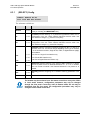
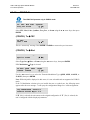
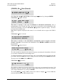
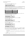
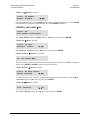
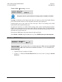
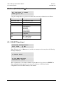
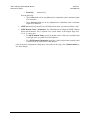
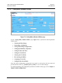
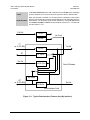
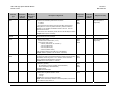
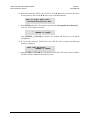
If TX Power Æ Imped(ance) is selected (this menu selection is available/displayed only when
the 70/140 MHz Modulator card is installed):
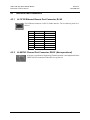
TX Impedance (Ohms):
50 75
( E)
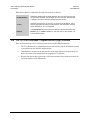
Note the following:
70/140 MHz
Select 50 or 75(Ω) using the arrow keys, then press ENTER.
L-Band
Not applicable.
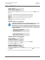
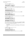
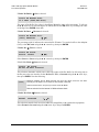
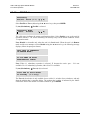
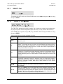
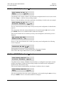
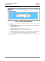
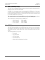
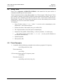
(CONFIG:) Tx Æ Scram
Tx Scrambling Index:
Gold-n = 000000
(▲ ▼ E)
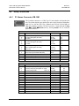
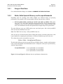
The Gold-n Index indicates the Physical Layer spreading sequence number, and can be set from 0
to 262,141. The default setting is all 0s. To edit, use the W X arrow keys to select the digit to be
edited, then use the ST arrow keys to change the value of the digit. Press ENTER when done.
6.3.1.3
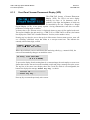
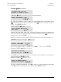
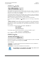
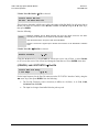
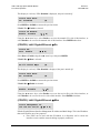
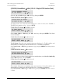
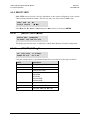
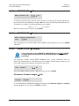
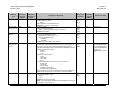
CONFIG: Rx
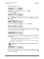
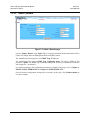
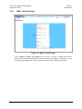
Rx: FEC Dem Code SymRate
Freq EbNo PLL
(E)
Select FEC, Dem(od), Code, SymRate, Freq, EbNo, or PLL using the W X arrow keys, then
press ENTER. Note the following:
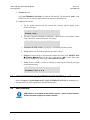
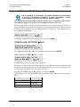
IMPORTANT
The CDM-710G operates only in DVB-S2 mode; this makes several Rx
parameters read-only. These parameters are resolved automatically and do not
need to be configured:
•
•
•
•
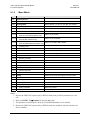
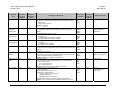
Rx: Dem (Demodulation Type)
Rx Dem Æ Inv (Spectrum Invert)
Rx Dem Æ Pilot
Rx: Code Rate
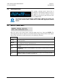
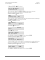
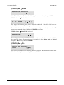
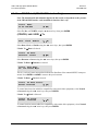
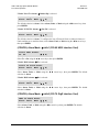
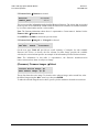
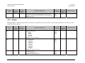
(CONFIG:) Rx Æ FEC
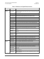
If Rx Æ FEC is selected:
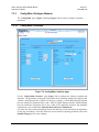
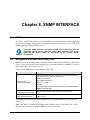
Rx FEC:
LDPC + BCH
(E)
This is a read-only status message. Press ENTER or CLEAR to return to the previous menu.
6–17