1
Model PDP Series 200 maxDPU4E Hardware Guide
Serial Ports
The DPU front chassis panel contains two serial ports, a female 9-pin D style
RS232C connector and a female 25-pin D-type connector. The 9-pin
RS232C connector is used to flash the DPU firmware with updates. The
25-pin D-type connector may be configured, by software, to support several
different interface standards.
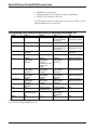
Table 2-1 provides the pin-outs for the 9-pin port. The pinouts of the 25-pin
port depends upon its usage.
Table 2-1. 9-pin Serial Port Pin-outs
Pin No.
Purpose
1
2
3
4
5
6
7
8
9
N.C. (N.C. = no connection)
RxD
TxD
N.C.
Circuit Ground
N.C.
RTS
CTS
N.C.
Backup Link
A 100Mbps Ethernet link is used to pass database information between an
active DPU and an inactive standby DPU. A custom category 5 cable (part
number 089424) connects the DPU backup pair together via the backup
link’s RJ-45 connector. Secondary DPUs will typically be installed in the
lower chassis just below the primary DPUs. To provide unobstructed access
to the key and mode switches, the backup cable should be dressed behind the
termination chassis in the wire tray.
2-2
Metso Automation MAX Controls Inc. • 278590 •