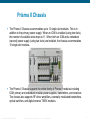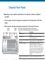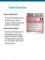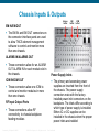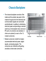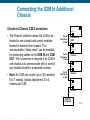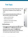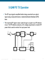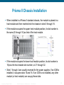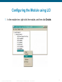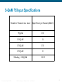
1
Prisma Optics Training Module 1 v3 ega ert S..fo.go.mh..com email: [email protected] Provided by: Mega Hertz 800-883-8839 V3 added 1310 & OBand© 2006 Cisco Systems, Inc. All rights reserved. Presentation_ID [email protected] www.go2mhz.com Cisco Confidential 1 Agenda Product Overview, products used in overlay Prisma II & XD Chassis Configuration and monitoring options 1550 Broadcast TX 1550 DWDM S-QAM TX 1550 DWDM S-QAM-FS TX 1310 & O-Band Multiwave TX Prisma EDFAs Presentation_ID Kirkpatrick 092509 © 2006 Cisco Systems, Inc. All rights reserved. Cisco Confidential 2 Prisma Chassis David Kirkpatrick © 2010 Cisco and/or its affiliates. All rights reserved. Cisco Confidential Prisma II Chassis The Prisma II Chassis accommodates up to 13 single-slot modules. This is in addition to the primary power supply. When an ICIM is installed (using two slots), the number of available slots drops to 11. When both an ICIM and a redundant (second) power supply (using two slots) are installed, the chassis accommodates 10 single-slot modules. The Prisma II Chassis supports the entire family of Prisma II modules including ICIM, primary and redundant modular power supplies, transmitters, and receivers. The chassis also supports RF driver amplifiers, externally modulated transmitters, optical switches, and digital reverse TX/RX modules. Presentation_ID Kirkpatrick 092509 © 2006 Cisco Systems, Inc. All rights reserved. Cisco Confidential 4 Chassis Front Panel Depending on your system requirements, the chassis is factory configured as either: Front access, with port and power connectors on the lower part of the front panel. Rear access, with port and power connectors on the back of the unit. 736762 736766 Presentation_ID Kirkpatrick 092509 144869 144870 (P2-CH-R-F-56-R-AAS)Chassis,Rear Acc,56F,2/AC Pwr (P2-CH-R-F-56-R-DDS)Chassis,Rear Acc,56F,2/-48VDC Pwr Part Description Power ON LED Illuminates when power is applied to the chassis. ALARM LED Illuminates if there is a failure in the chassis cooling fan tray. LOCAL CRAFT INTERFACE Used to connect a PC to the chassis for (LCI) Port module setup when no ICIM is installed. CHASSIS ID Switch Allows the operator to assign an identification number to every Prisma II Chassis for addressing by ICIM, LCI, or TNCS software. When using the ICIM, this number is referred to as the shelf number. Each chassis connected to an individual ICIM must have a unique chassis ID number. Electrostatic Discharge (ESD) Used prior to touching any modules. Jack © 2006 Cisco Systems, Inc. All rights reserved. Cisco Confidential 5 Chassis Connections Connector Interface Panel The connector interface panel houses the electrical, signal, and alarm connectors, as well as the power inlets required for chassis operation. Chassis Inputs and Outputs Chassis inputs and outputs consist of cable assemblies that connect the backplane to ALARMS IN, ALARMS OUT, EM IN, EM OUT, ICIM IN, ICIM OUT, CLOCK INPUT, RF IN, RF OUT and the Ground Stud. Presentation_ID Kirkpatrick 092509 © 2006 Cisco Systems, Inc. All rights reserved. Cisco Confidential 6 Chassis Inputs & Outputs Alarms In/Out EM IN/EM OUT EM In/Out ICIM In/Out The EM IN and EM OUT connectors on the connector interface panel are used to allow TNCS element management software to control and monitor more than one chassis. ALARMS IN/ALARMS OUT These connectors allow for an ALARM OUT ALARM IN for each module slot in the chassis. ICIM IN/ICIM OUT These connectors allow one ICIM to control and monitor modules in more than one chassis. RF Input Output Ports These connections allow RF connectivity to chassis backplane feeding modules Presentation_ID Kirkpatrick 092509 © 2006 Cisco Systems, Inc. All rights reserved. Power Supply Inlets The primary and secondary power supplies are inserted from the front of the chassis. The power supply connectors mate with the factoryinstalled power inlet connectors on the backplane. The inlets differ according to which type of power supply is installed. Either AC or DC supplies can be installed in the chassis when the proper power inlets are installed Cisco Confidential 7 Chassis Backplane The chassis backplane consists of the inside and the outside rear panel of the chassis through which the electrical and communication signals are connected and distributed. In addition to distributing electrical power and providing a common serial bus, the backplane also connects 4 RF ports (2 connectors are standard, 2 others are optional) to each of the 14 module connectors. Module connectors inside the chassis accommodate electrical power, digital signals, and analog signals. The connectors are inherently self-guiding and allow a blind mate connection. Presentation_ID Kirkpatrick 092509 © 2006 Cisco Systems, Inc. All rights reserved. Cisco Confidential 8 Connecting the ICIM to Additional Chassis Chassis-to-Chassis ICIM Connections The Prisma II platform allows the ICIM to be located in one chassis and control modules located in several other chassis. This communication “daisy-chain” can be enabled by connecting cables to the ICIM IN and ICIM OUT. This connection is required if an ICIM in one chassis is to communicate with or control any module located in a separate chassis. Note: An ICIM can control up to 140 modules 6 to 7 chassis, typical deployment 3 to 4 chassis per ICIM. ICIM Out Serial Extension Cable EM In Chassis with ICIM ICIM In ICIM Out Serial Extension Cable Chassis ICIM In ICIM Out Serial Extension Cable Chassis ICIM In ICIM Out Chassis ICIM Out Terminator Presentation_ID Kirkpatrick 092509 © 2006 Cisco Systems, Inc. All rights reserved. Cisco Confidential TP477 9 Connecting the ICIM to Additional Chassis ICIM IN and ICIM OUT Connectors Every chassis has a DB9 ICIM IN and a DB9 ICIM OUT connector for the purpose of chassis-to-chassis ICIM2 connections. ICIM IN is a female connector and ICIM OUT is a male connector. The cable required for both ICIM IN and ICIM OUT connections is a shielded 9-wire serial extension cable, DB9 Female to DB9 Male. Cisco # 180143 CIFA# 144856 All chassis connected in this daisy-chain must have a unique chassis ID number. If the ICIM OUT terminator (4013014) that ships with the ICIM is not installed on the last chassis of a daisy-chain connection, faulty communication with the ICIM may occur. The ICIM OUT port of the last chassis in the daisy-chain must be terminated with an ICIM OUT terminator, part number 4013014 Presentation_ID Kirkpatrick 092509 © 2006 Cisco Systems, Inc. All rights reserved. Cisco Confidential 10 External Alarms Connections Master/Slave Operation All Prisma II modules ship from the factory configured as a master. The LCI, TNCS software, or the ICIM can be used to reconfigure a module as a slave or as redundant (slave). The Chassis allows for local hard-wired redundancy by using the ALARM IN and ALARM OUT connectors. A pair of modules can be configured so that if the master fails, the slave takes over by using the ALARM IN and ALARM OUT connectors ALARM IN and ALARM OUT Connectors The Prisma II Chassis provides two connectors for external alarms to and from each module slot. These alarm connectors are located in two 37-pin D-connectors (DB-37) and are labeled ALARM IN and ALARM OUT. • NOTE: Master Slave feature requires Redundancy Interface Panel (RIP). The RIP serves as an extension to the two DB-37 connectors labeled ALARM IN and ALARM OUT – see IO Guide for further details Presentation_ID Kirkpatrick 092509 © 2006 Cisco Systems, Inc. All rights reserved. Cisco Confidential 11 Power Supply There are two versions of the Prisma II Power Supply, AC or DC. The type that you use depends on the input voltage to your system. The two versions are functionally identical, and differ only in cable connections to chassis and input voltages. • AC Supply Cisco 4012765 CIFA 16365 • Voltage requirements 90 to 265 VAC • DC Supply Cisco 716312.001.000.BA, CIFA 145084 • Voltage requirements -40 to -75 VDC Front Panel Indicators The front panel of the power supply has a green ON indicator and a red ALARM indicator. The ON indicator illuminates when external power has been applied. The ALARM indicator illuminates when the power supply has a problem supplying one of the required output voltages to power the chassis. Presentation_ID Kirkpatrick 092509 © 2006 Cisco Systems, Inc. All rights reserved. Cisco Confidential 12 Fan Tray The Prisma II Fan Tray provides cooling to the Prisma II Chassis and monitors the Prisma II Power Supplies. The fan tray is installed in the top of the Prisma II Chassis at the factory. It can be removed for maintenance or inspection by loosening the two screws located on either side of the front panel. Important: Do not operate Chassis without a fan tray installed. If a fan tray is not installed in the chassis, the ICIM will not communicate with any of the modules in that chassis • Fan Tray replacement # 741419 • Fan Kit, fans only # 741421 Presentation_ID Kirkpatrick 092509 © 2006 Cisco Systems, Inc. All rights reserved. Cisco Confidential 13 PII ICIM2 Front Panel Part LCD screen Function Displays the ICIM2 menus, alarms, and status information. 12-key numeric Used to navigate the ICIM2 menus and configure the keypad application modules. Ethernet Directly connects the ICIM2 to an IP network. The connector ICIM2 Ethernet port is suitable for connection to intra-building wiring, non-exposed wiring or cabling only. Yellow LED on Glows when the Ethernet port is operating in full Ethernet duplex. connector Blinks when collisions occur on the Ethernet port. Green LED on Ethernet connector Glows when a link is established on the Ethernet port. Blinks during data activity on the Ethernet port. RS232 connector Used to connect a PC to the Prisma II system for CLI Old pic, RS232 communication and setup. not shown Presentation_ID Kirkpatrick 092509 © 2006 Cisco Systems, Inc. All rights reserved. Cisco Confidential 14 Checking the Operating Status using the ICIM2 You can use the ICIM to check status of all operating parameters of a module. All status information is displayed on the ICIM LCD. 1 At the MAIN menu, press the 2 Press the key to highlight the Shelf and Slot fields. key to address the Shelf number. Then press the key or the key to scroll to the number of the desired shelf. 3 Press the key. The Slot field is highlighted. 4 Press the key or the 5 Press the key. The MODULE menu appears on the ICIM LCD. 6 Press the key. 7 Press the key or the key to scroll through the monitored parameters until you find the parameter of interest. 8 Check the status of the desired parameter or select other parameters to monitor. When finished, press the Presentation_ID Kirkpatrick 092509 key to scroll to the number of the desired slot. key to return to the MAIN menu © 2006 Cisco Systems, Inc. All rights reserved. Cisco Confidential 15 Prisma XD Chassis David Kirkpatrick © 2010 Cisco and/or its affiliates. All rights reserved. Cisco Confidential Prisma II XD Platform The Prisma II XD Platform is a configurable and expandable system for providing transmit and receive functions to fiber-optic communications networks. The Prisma II XD Platform consists of the following products. • Prisma II XD Chassis # 4022058 CIFA 63436 Chassis NO ICIM, # 4023768 CIFA 63437 Chassis with ICIM • Prisma II XD fan assembly • Prisma II XD AC-to-DC bulk power supply modules (one or two) #1005444 • Prisma II ICIM2-XD Intelligent Communications Interface Module #4022060 • Prisma II High-Density application modules • Prisma II XD Chassis application module blanking panels • http://www.cisco.com/en/US/products/ps8863/index.html Presentation_ID Kirkpatrick 092509 © 2006 Cisco Systems, Inc. All rights reserved. Cisco Confidential 17 XD Fan Assembly The chassis uses a negative pressure fan system to pull cooling air from the ambient environment. Three fans are housed in a field-replaceable assembly attached at the back of the chassis. The fan assembly can be removed for inspection and maintenance, to provide access to the DC-to-DC converters inside the chassis, or to remove either of the AC-to-DC bulk power supply modules. Presentation_ID Kirkpatrick 092509 © 2006 Cisco Systems, Inc. All rights reserved. Cisco Confidential 18 Chassis Power Supply Architecture The chassis can operate from utility AC power or from external -48 VDC power. For AC operation, one or two AC-to-DC bulk power supply modules are installed in the chassis. Each of these modules supplies -48 VDC power to one of two DC-to-DC converter assemblies inside the chassis For DC operation, one or both AC-to-DC bulk power supply modules are removed, and power for one or both internal DC-to-DC converter assemblies is supplied from external -48 VDC power source. The DC power connector can serve one of two functions, depending on the power supply configuration: When the associated AC-to-DC bulk power supply slot is empty, its DC power connector acts as an inlet for external -48 VDC. When the associated AC-to-DC bulk power supply slot is populated, its DC power connector acts as an outlet for -48 VDC from the bulk power supply module. Presentation_ID Kirkpatrick 092509 © 2006 Cisco Systems, Inc. All rights reserved. Cisco Confidential 19 Chassis Power Supply Architecture The following diagram shows the general power supply architecture for a single Prisma II XD Platform chassis. +24 VDC +5 VDC -5 VDC 0 VDC Application Module Power Bus DC-to-DC Converter Module A AC-to-DC Bulk Supply Module A AC IN A DC-to-DC Converter Module B RETURN RETURN -48 VDC -48 VDC DC IN/OUT A DC IN/OUT B AC-to-DC Bulk Supply Module B AC IN B Each AC-to-DC bulk power supply module feeds a separate, dedicated DC-to-DC converter assembly. The chassis ships with two DC-to-DC converters installed, but without either AC-to-DC bulk power supply module installed. TP552 Each DC-to-DC converter can power a full chassis on its own. The use of dual independent converters, together with dual AC-to-DC bulk power supplies, allows for full power supply redundancy. Presentation_ID Kirkpatrick 092509 © 2006 Cisco Systems, Inc. All rights reserved. Cisco Confidential 20 ICIM2-XD The ICIM2-XD provides users with access to application module configuration settings, status monitoring, and alarm monitoring. The ICIM2-XD is logically identical to the ICIM2 module used in Prisma II chassis. However, the ICIM2-XD is physically smaller than the ICIM2 and lacks a front-panel keypad or liquid-crystal display. Part Ethernet connector RS232 connector Function Directly connects the ICIM2-XD to an IP network. The frontpanel Ethernet port is suitable for connection to intra-building wiring, non-exposed wiring or cabling only. Used to connect a co-located PC to the Prisma II Enhanced system for local console port CLI communication and setup. Note: When a Prisma II chassis and a Prisma II XD chassis are part of a daisy-chain connection of two or more chassis, a single ICIM2 or ICIM2XD can and must be used to control both chassis. Presentation_ID Kirkpatrick 092509 © 2006 Cisco Systems, Inc. All rights reserved. Cisco Confidential 21 Step 1: Install Chassis in a Rack (Just in case you have never installed a piece of equipment in a rack) 1. Use a torque wrench to tighten the bracket mounting screws to 12 to 14 in-lbs 2. Position the chassis in the rack with the fan assembly installed, but otherwise empty. 3. Insert a mounting screw through each of the four mounting holes on chassis front panel, and then into the rack. 4. Use a medium-sized Phillips-head screwdriver to tighten each mounting screw until it is tight. 5. Install additional cable and fiber management hardware as needed and in accordance with local practice. Presentation_ID Kirkpatrick 092509 © 2006 Cisco Systems, Inc. All rights reserved. Cisco Confidential 22 Step 2: ICIM In ICIM Out Cable Connections Chassis-to-Chassis ICIM Connections The Prisma II XD platform allows the ICIM2-XD to be located in one chassis and monitor application modules in other chassis. This communication “daisy-chain” can be enabled by connecting cables to the ICIM IN and ICIM OUT connectors on the chassis interface panel. Presentation_ID Kirkpatrick 092509 © 2006 Cisco Systems, Inc. All rights reserved. Cisco Confidential 23 Step 2: ICIM In ICIM Out Cable Connections 1. Connect the serial extension cable (CIFA 144856) from the ICIM OUT of the chassis containing the ICIM2-XD to the ICIM IN connector of the second chassis. 2. Connect a serial extension cable from the ICIM OUT of the second chassis to the ICIM IN of the third chassis, if installed, third chassis to fourth etc. 3. Change the chassis ID numbers as needed to give each chassis an appropriate unique ID number. See To Change the Chassis ID Number below for further details and cautions. 4. The ICIM OUT port of the last chassis in the daisy-chain must be terminated with an ICIM OUT terminator, part number 4013014, which ships with the ICIM2-XD. Presentation_ID Kirkpatrick 092509 © 2006 Cisco Systems, Inc. All rights reserved. Cisco Confidential ICIM Out Serial Extension Cable EM In Chassis with ICIM ICIM In ICIM Out Serial Extension Cable Chassis ICIM In ICIM Out Serial Extension Cable Chassis ICIM In ICIM Out Chassis ICIM Out Terminator TP477 24 Step 2: Change Chassis ID Number 1. Locate the chassis ID switch at upper right on the front panel of each chassis. The switch can be set to any two-digit value from 00 to 99 (but avoid setting the value to 00, as explained below). 2. Use the chassis ID switch to set each chassis ID number to a unique value. Note: The chassis ID number can be changed while the chassis is under power. However, the new ID number will not become effective until chassis power is cycled or the ICIM2-XD is rebooted. The chassis numbering scheme used is discretionary, except that each interconnected chassis must have a unique ID number. CAUTION: Setting the chassis ID to 00 is not recommended as it causes the entity MIB to violate RFC-2737 by creating an invalid object identifier. This may affect operation with some management systems that use the entity MIB. In particular, attempts to access the fans (in virtual slot 0) in chassis 00 will fail if made via serial TNCS (or ROSA-EM) or LCI. Presentation_ID Kirkpatrick 092509 © 2006 Cisco Systems, Inc. All rights reserved. Cisco Confidential 25 Step 3: Make Electrical Connections The chassis back panel has an IEC standard AC power inlet and a threeconductor DC power connector for each bulk DC power supply module slot. The AC power inlet accepts line voltage at 100 to 240 VAC, 50 or 60 Hz. The DC power connector accepts DC input voltage at -40 to -72 VDC (-48 VDC nominal). The power connectors on the left side of the chassis supply power to the left power supply slot, while those on the right supply power to the right power supply slot. Presentation_ID Kirkpatrick 092509 © 2006 Cisco Systems, Inc. All rights reserved. Cisco Confidential 26 Step 3: Make Electrical Connections ~ DC Power Systems External -48 VDC operating power for each DC-to-DC converter (mounted in the chassis just behind the fan assembly) enters the chassis via a dedicated DC power inlet mounted on the chassis back panel. The voltage input range for DC power systems is -40 VDC to -72 VDC. Use cable 4011730 for DC wiring. The #16 AWG wiring from the external 48 VDC supply is attached to a 3-pin nylon connector which, in turn, plugs into the DC power inlet. Order additional nylon plugs and connector pins from your preferred supplier, as follows: • Molex #03-12-1036 nylon 3-pin connector • Molex #18-12-1222 crimp socket contact (3) Use a Molex Crimp Service Tool #63811-1000 or equivalent to crimp the pins to the cable. Presentation_ID Kirkpatrick 092509 © 2006 Cisco Systems, Inc. All rights reserved. Cisco Confidential 27 Step 4: Install the ICIM2 Note: Chassis can be ordered with or without ICIM ~ follow steps if adding ICIM to non ICIM chassis 1. Remove the blanking panel covering the ICIM slot in the lower right corner of the chassis back panel. 2. Hold the ICIM2-XD so that the front panel silkscreen is in correct reading position. 3. Align the two ridges on the bottom of the ICIM2-XD with the module guide slots located in the chassis. 4. Gently slide the ICIM2-XD into the chassis until its power and communications connections join connectors on the back plane bus and its front panel rests against the chassis. 5. Tighten the retaining screws on either side of the ICIM2-XD to secure to chassis Presentation_ID Kirkpatrick 092509 © 2006 Cisco Systems, Inc. All rights reserved. Cisco Confidential 28 Connecting RF Cables The chassis back panel has two RF connectors, A and B, for each application module slot. Each pair of RF connectors is numbered (1-16) to show its corresponding slot number. RF port A, leftmost in each pair, is marked by a black semicircle or nut at the base of the connector. RF port A provides connection to the upper of two independent RF channels on the chassis midplane, while RF port B provides connection to the lower RF channel. Presentation_ID Kirkpatrick 092509 © 2006 Cisco Systems, Inc. All rights reserved. Cisco Confidential 29 Equipment Configuration David Kirkpatrick © 2010 Cisco and/or its affiliates. All rights reserved. Cisco Confidential Equipment Configuration There are several different ways to configure the equipment. Command line interface (CLI) ICIM2 Web Interface ICIM2 keypad (PII chassis only) Simple Network Management Protocol (SNMP) Local Craft Interface (LCI) This section we will cover LCI & ICIM2 Wed Interface For further information on configuration using the CLI, see the Prisma II Platform Remote User Interface Guide, part number 4012441. Presentation_ID Kirkpatrick 092509 © 2006 Cisco Systems, Inc. All rights reserved. Cisco Confidential 31 Equipment Configuration Local Craft Interface (LCI) David Kirkpatrick © 2010 Cisco and/or its affiliates. All rights reserved. Cisco Confidential Communications and Control Local Craft Interface (LCI) LCI Port The first display represents the chassis and contained hardware. Drill down via the tree view or “double click” on a module opens the device control screen. RS232 Second display SSC LCI The Local Craft Interface is a DB9F connector found on the front of each and every Prisma II and XD chassis. This serial port is addressed via a terminal type program that can be run on a laptop or other PC. A serial cable is connected to this port and the serial port of the PC. The application can poll all the hardware in the rack returning current configuration and alarm information 1. All gain settings 2. All alarm settings 3. Software and firmware versions 4. Serial number 5. Address information 6. Module type 7. Equipment status Serial cable can be purchased locally or ordered from the factory part number 180143. Presentation_ID Kirkpatrick 092509 © 2006 Cisco Systems, Inc. All rights reserved. Cisco Confidential 33 LCI Function LCI is software that functions as a user interface for the Prisma II & XD platform. LCI is installed on a computer, which is then connected to a Prisma Chassis. Using LCI, you can configure and monitor the modules in the chassis to which the computer is connected. System Requirements You will need the following computer software and hardware to run LCI. Computer Requirements Pentium II 300 MHz processor or equivalent 128 MB RAM 10 MB available hard drive space Windows 95 or later operating system software Cable Requirements The required cable is a standard serial extension cable, DB9 Female to DB9 Male. This cable can be purchased locally or ordered from the factory as part number 180143. The connectors are a serial 9-pin D-shell (EIA 574/232). Presentation_ID Kirkpatrick 092509 © 2006 Cisco Systems, Inc. All rights reserved. Cisco Confidential 34 Installing LCI You can go to Cisco.com -> Support and search for Prisma II. Click on “Prisma II Platform” and then “HFC and Optics Software” to get here: Click here for latest devtypes Click here for latest LCI Presentation_ID Kirkpatrick 092509 © 2006 Cisco Systems, Inc. All rights reserved. Cisco Confidential 35 Connecting Your Computer to the Chassis Before you start LCI, you must first connect your computer to the chassis that contains the module(s) you want to check. LCI only communicates with modules installed in the chassis to which your computer is connected. To check other modules, you must connect your computer to the chassis in which they are installed. If LCI does not communicate with a module in the chassis to which your computer is connected, it may be necessary to update the LCI application. Latest rev as of 8.25.11 is 2.4.4 To Connect a Computer to the Chassis 1. Plug one end of a 9-pin RS-232 serial extension cable into your computer. Internet LCI Web Browser 2. Plug the other end of the cable into the LCI port, labeled Local Craft Interface Presentation_ID Kirkpatrick 092509 © 2006 Cisco Systems, Inc. All rights reserved. Cisco Confidential 36 Connecting Your Computer to the Chassis Before you start LCI, you must first connect your computer to the chassis that contains the module(s) you want to check. LCI only communicates with modules installed in the chassis to which your computer is connected. To check other modules, you must connect your computer to the chassis in which they are installed. If LCI does not communicate with a module in the chassis to which your computer is connected, it may be necessary to update the LCI application. To Connect a Computer to the Chassis 1. Plug one end of a 9-pin RS-232 serial extension cable into your computer. LCI 2. Plug the other end of the cable into the LCI port, labeled Local Craft Interface Presentation_ID Kirkpatrick 092509 © 2006 Cisco Systems, Inc. All rights reserved. Cisco Confidential 37 Starting LCI Software 1. Double-click the LCI icon on your Windows desktop Result The LCI Detect Configuration window appears as shown below 2. In the LCI Detect Configuration window, select the appropriate COM port, chassis ID, and chassis type, and then click Start. Presentation_ID Kirkpatrick 092509 © 2006 Cisco Systems, Inc. All rights reserved. Cisco Confidential 38 Equipment Configuration Web Interface David Kirkpatrick © 2010 Cisco and/or its affiliates. All rights reserved. Cisco Confidential Intelligent Communications Interface Module The XD ICIM2 provides an interface to Prisma platform application modules via command line interface (CLI), Web Browser or SNMP The ICIM can support multiple chassis in a daisy-chain connection ICIM Web Interface Remote Access – allows access to the Web User Interface via a Mozilla (Unix) or Internet Explorer 6.0 (Windows) Browsers Via the ICIM Web Interface you can access the following ICIM Data Module Data Current Alarms Module Alarms Module Control Module Monitors System Information User Management Presentation_ID Kirkpatrick 092509 © 2006 Cisco Systems, Inc. All rights reserved. Cisco Confidential 40 Web Interface Introduction The ICIM Web Interface is a set of HTML pages hosted by the web server in the ICIM2 and ICIM2-XD. These pages display information about the ICIM2 and other modules in its domain. You navigate and interact with the Web Interface through the use of menus and hyperlinks, just as with a typical web site The Web Interface provides a subset of CLI functionality using SNMP as the underlying communication protocol. However, using the Web Interface requires no knowledge of either SNMP or CLI. Note: For these pages to work properly, both JavaScript and cookies must be enabled in your web browser. Presentation_ID Kirkpatrick 092509 © 2006 Cisco Systems, Inc. All rights reserved. Cisco Confidential 41 Web Browsers Supported Mozilla for Unix or Linux, version 1.7 Microsoft Internet Explorer for Windows, version 6 CAUTION: Before closing the browser or tab in which the Web Interface session is running, be sure to log out of the Web Interface using the Logout link at the bottom left of the navigation pane. If you close the browser or tab before logging out, the session will hang open for the duration of a timeout interval. This may prevent access to the ICIM2 through either the CLI or the Web Interface by you or other users. This may also create a breach of security by enabling unauthorized users to access the Web Interface at the previous user authorization level by opening a new browser tab. Presentation_ID Kirkpatrick 092509 © 2006 Cisco Systems, Inc. All rights reserved. Cisco Confidential 42 Information Color Code Items shown in red signal conditions that require prompt user attention. Items shown in blue are links to pages with more details. Items shown in black signal normal conditions or values falling within nominal limits. Presentation_ID Kirkpatrick 092509 © 2006 Cisco Systems, Inc. All rights reserved. Cisco Confidential 43 Installation The Web Interface is already resident in the ICIM2 firmware. All that is needed for access is to install an appropriate web browser and point it to the ICIM2 IP address. Your system administrator can provide the IP address for this page in your installation. To Install the Web Interface for Windows To download the instructions for installing Internet Explorer 6 for Windows, use your current browser to access the links for installation provided at http://www.microsoft.com. To Install the Web Interface in Solaris To download the instructions for installing Mozilla 1.7 on Sparc Workstations (Solaris 8 and 9), use your current browser to access the links for installation provided at http://www.mozilla.org. Presentation_ID Kirkpatrick 092509 © 2006 Cisco Systems, Inc. All rights reserved. Cisco Confidential 44 Login and Logout To use the Web Interface, you must enter a valid user name and password. The default user name and password are given below. User name: Administrat0r Password: AdminPassw0rd Note: Both the default user name and the default password have a zero (0) in place of the expected "o" character. For security reasons, it is recommended that the default user name be changed immediately. For additional information, see User Management in the appropriate system guide. Presentation_ID Kirkpatrick 092509 © 2006 Cisco Systems, Inc. All rights reserved. Cisco Confidential 45 To Login 4. Press the Enter key or click the Go button. The ICIM Login page appears as shown below. Presentation_ID Kirkpatrick 092509 © 2006 Cisco Systems, Inc. All rights reserved. Cisco Confidential 47 To Login 5. Type your User name and Password in the fields provided, and then click the Login button. The ICIM Welcome page appears as shown below. 6. Use one of the following navigation methods as appropriate: Click Next to go to the System View page. Or, wait 10 seconds to be taken to System View automatically. Use the menu at the left of the screen to go directly to System View or to choose another page of interest Presentation_ID Kirkpatrick 092509 © 2006 Cisco Systems, Inc. All rights reserved. Cisco Confidential 48 Using System View The System View page displays manufacturing information for the ICIM2 and selected modules. System View also allows you to view the current alarms for the ICIM2 and any application modules in the domain. Presentation_ID Kirkpatrick 092509 © 2006 Cisco Systems, Inc. All rights reserved. Cisco Confidential 49 Using System View This table contains at least one, and possibly two, hyperlinks to other pages of the interface. Clicking the details link in the title takes you to the ICIM Details screen. Clicking the Alarm Count link when alarms are active takes you to the Current Alarms table. These pages are described in later sections of this chapter Presentation_ID Kirkpatrick 092509 © 2006 Cisco Systems, Inc. All rights reserved. Cisco Confidential 50 To View Module Summary The Module Summary table at the bottom of the System View page lists the modules in the ICIM2 domain and identifies their chassis and slot locations, module types (if reported by the module) and devtypes, and the number of alarms currently active Note: Clicking the Details link for a particular module displays the Module Details Presentation_ID Kirkpatrick 092509 © 2006 Cisco Systems, Inc. All rights reserved. Cisco Confidential 51 To View Current Alarms To view current alarms in the system, click the Current Alarms submenu item. Presentation_ID Kirkpatrick 092509 © 2006 Cisco Systems, Inc. All rights reserved. Cisco Confidential 52 To View Current Alarms The Current Alarms page appears, displaying any active alarms in a table similar to the one shown below. In this table: Chas/Slot is the number of the chassis and slot in which the module is located. Label is the name of the alarm. Time is the time at which the module went into alarm. Description is the module description Presentation_ID Kirkpatrick 092509 © 2006 Cisco Systems, Inc. All rights reserved. Cisco Confidential 53 To View Module Details When you click Details in the Module Summary table in System View, the Module Details screen for the corresponding module appears, as shown in the following example. Presentation_ID Kirkpatrick 092509 © 2006 Cisco Systems, Inc. All rights reserved. Cisco Confidential 54 Module Details Submenu When the Module Details screen appears, a submenu lets you select Alarms, Thresholds, Controls, and Monitors for the module Presentation_ID Kirkpatrick 092509 © 2006 Cisco Systems, Inc. All rights reserved. Cisco Confidential 55 Thresholds To view the current threshold values for all alarms for the chosen module, click the Thresholds submenu option. The Module Alarm Thresholds table appears as shown below Presentation_ID Kirkpatrick 092509 © 2006 Cisco Systems, Inc. All rights reserved. Cisco Confidential 56 Thresholds If any of the alarms have user-adjustable threshold values, these values are shown in ruled fields to indicate that they are editable. To change a threshold value, click inside the field, type the desired value, and then either click the Apply button to the right of the row containing the field. Or, you may press Enter to invoke the changes on that row immediately. To abort the change, click the Cancel button before clicking Apply. Clicking Cancel reloads the page, discarding any unapplied changes. After you click Apply, a popup window appears asking you to confirm the save operation Presentation_ID Kirkpatrick 092509 © 2006 Cisco Systems, Inc. All rights reserved. Cisco Confidential 57 Controls To review the control parameters for the chosen module, click the Controls submenu option. The Module Controls table appears as shown below Presentation_ID Kirkpatrick 092509 © 2006 Cisco Systems, Inc. All rights reserved. Cisco Confidential 58 Controls To change a control value, click inside the field, type the desired value, and then either click the Apply button to the right of the row containing the field. Or, you may press Enter to invoke the changes on that row immediately. To abort the change, click the Cancel button before clicking Apply. Clicking Cancel reloads the page, discarding any unapplied changes After you click Apply, a popup window appears asking you to confirm the save operation: Presentation_ID Kirkpatrick 092509 © 2006 Cisco Systems, Inc. All rights reserved. Cisco Confidential 59 To Log Out Complete the following steps to log out of the Web Interface. 1. Click Logout in the main menu. The Web Interface Logout page appears as shown below 2. Close your browser window as a security precaution Presentation_ID Kirkpatrick 092509 © 2006 Cisco Systems, Inc. All rights reserved. Cisco Confidential 60 1550 Broadcast EMT David Kirkpatrick © 2010 Cisco and/or its affiliates. All rights reserved. Cisco Confidential BC TX EMT Description The Prisma II 1550 nm Externally Modulated Transmitters (EMTs) are plug-in modules for the Prisma II platform. Microprocessor control allows ease of installation and flexibility of application. The transmitter design includes an array of capabilities, such as low RF input level, and elective Automatic Gain Control (AGC) Options Multiple ITU and Non ITU wavelength options (recommend using ITU) Long Reach EMT, PII-15TXL ITU40 #737283 CIFA 28312, ITU18 #737287 CIFA 64028 Extended Reach EMT, PII-15TXX ITU40 #737279 NO CIFA, ITU18 #737280 NO CIFA Features 10dBm output Front panel green light emitting diode (LED) to indicate operating status Front panel red LED to indicate alarm status -20 dB test point relative to input Product Application Transporting broadcast analog and QAMs HE to Hub or Node Presentation_ID Kirkpatrick 092509 © 2006 Cisco Systems, Inc. All rights reserved. Cisco Confidential 62 1550 EMT Operations The Prisma II 1550 nm Transmitters receive an RF signal through a connector on the rear of the module. The RF input signal is then amplified and converted to an optical signal. Broadcast RF Input 20 dBmV/Ch (78 NTSC) RF Amp Voltage Controlled Attenuator RF Amplifiers PreDistortion J1 DFB Laser Narrowcast RF Input 12 dB Below Broadcast - RF Signal - Optical Signal - Control Signal Optical Modulator SBS Suppression Front Panel Test Point 20 dB Below Broadcast J2 * Optical Output * Modulator Bias Control CCB or Equivalent Embedded Controller * Dual optical outputs, J1 and J2, on a P2-15TXL Transmiter Single optical output, J1 only, on a P2-15TXX Transmitter Presentation_ID Kirkpatrick 092509 © 2006 Cisco Systems, Inc. All rights reserved. Cisco Confidential TP625 63 Front Panel Feature Description Alarm indicator Illuminates or blinks when an alarm condition occurs. Power On indicator Illuminates when power is supplied to the module. Optical output Connects the output signal to the optical cable. -20 dB test point Provides a -20 dB sample of the RF input signal. NOTE: The PII-15TXL is a two-port device, while PII-15TXX is a one-port device. Secondary output (J2) may have some performance degradation as compared with primary output. Use primary (J1) for main path secondary for backup Presentation_ID Kirkpatrick 092509 © 2006 Cisco Systems, Inc. All rights reserved. Cisco Confidential 64 Configuration Methods and Summary Methods Configuration Summary Command line interface (CLI) Using any of the above methods, you can configure the following parameters. ICIM Web Interface Simple Network Management Protocol (SNMP) Enable Laser Laser Mode Local Craft Interface (LCI) AGC ICIM keypad (PII chassis only) RF Drive Level to the Laser Optical Modulation Index (OMI) Level Master/Slave Mode RFLasSet Length (km) LowRF Alarm Inhibit Presentation_ID Kirkpatrick 092509 © 2006 Cisco Systems, Inc. All rights reserved. Cisco Confidential 65 Connecting RF Cables The chassis back panel has four RF connectors, A, B, C & D for each application module slot. Each of RF connectors is numbered to show its corresponding slot number. “D” Not used with EMT “C” Not used with EMT “B” NC Input “A” BC Input Presentation_ID Kirkpatrick 092509 © 2006 Cisco Systems, Inc. All rights reserved. Cisco Confidential 66 Operation Using LCI 1. Right-click the chassis, and then click Open. Result: A graphic representation of the chassis appears Presentation_ID Kirkpatrick 092509 © 2006 Cisco Systems, Inc. All rights reserved. Cisco Confidential 67 Operation Using LCI 2. Double-click the module whose information you want to view or configure. Result: The Module Details window appears Presentation_ID Kirkpatrick 092509 © 2006 Cisco Systems, Inc. All rights reserved. Cisco Confidential 68 Operation Using LCI 3. Under Controls, double-click the parameter you want to configure. Result: The Change Value Dialog box appears. This example shows the dialog box for the RF Drive Setting parameter. 4. Depending on the parameter you chose, select or type a new value. 5. Click Execute. Result: The new value appears next to the parameter. Presentation_ID Kirkpatrick 092509 © 2006 Cisco Systems, Inc. All rights reserved. Cisco Confidential 69 EMT Operating Status Parameters Parameter Name (LCI) Optical Output 1 Power Optical Output 2 Power (TXL) Laser Bias RF Input Module Temperature CP Lock TEC Current ICIM Abbreviation OutPwr1 Function Typical Value Displays optical output power at port 1. +10.0 dBm OutPwr2 (TXL) Displays optical output power at port 2. +10.0 dBm LasBias InRF ModTemp Displays measured laser bias current. Displays RF input level. Displays module temperature. CPLock TecCur Indicates constant power loop lock. Indicates laser thermoelectric cooler current. 270 mA 0 dB Ambient °C + 30°C 0.4 0.2 A Laser Temperature LasTemp Displays laser temperature. 30°C Tx Type TxType TXX or TXL Modulator Bias SBS 2 GHz PLL SBS 6 GHz PLL SBS 2 GHz Power ModBias Sbs1Stat Sbs2Stat Psbs2G Indicates Transmitter Extended Reach (TXX) or Long Reach (TXL). Indicates modulator bias voltage level. SBS phase lock loop 1 lock status. SBS phase lock loop 2 lock status. Indicates 2 GHz SBS power level. SBS 6 GHz Power Psbs6G Indicates 6 GHz SBS power level. 120.0 -5V Supply Voltage -5VInt Displays internal -5 VDC supply voltage. -5 VDC -12V Supply Voltage -12VInt Displays internal -12 VDC supply voltage. -12 VDC +12V Supply Voltage Displays internal +12 VDC supply voltage. +12 VDC Presentation_ID Kirkpatrick 092509 +12VInt © 2006 Cisco Systems, Inc. All rights reserved. Cisco Confidential 0.128 VDC LOCK LOCK 90.5 70 EMT Configurable Parameters Parameter Name (LCI) Enable Laser ICIM Abbreviation Enable Laser Mode LasMode AGC Mode RF Drive Setting AGC RFDrive OMI Level Setting OMISet Description Values Default Enables or disables amplifier operation, i.e., turns the laser on or off. Selects one of two laser operating modes: constant current (i.e., constant wavelength) or constant power. ON (1) = Enabled OFF (0) = Disabled Constant Current (ConstCur) ON (1) Turns automatic gain control on or off. Constant Power (ConstPwr) ON (1) Off (0) Sets the relative RF drive level into the -6.0 dB to +1.0 dB in transmitter. Only effective when AGC is off 0.5 dB steps (manual gain control). (Negative decreases drive, positive increases drive) Sets the optical modulation index level. Only -6.0 dB to +1.0 dB in effective when AGC is on. 0.5 dB steps (Negative decreases Note: When AGC is active, it maintains a drive, positive constant OMI for input powers between -3 dB and +1 dB from nominal when OMI level increases drive) is set to 0 dB. ConstPwr OFF (0) 0.0 dB 0.0 dB In general, guaranteed AGC range is (-3 + OMI Level) dB to +1 dB. For example, for an OMI level setting of +1 dB, the guaranteed AGC range is 2 dB to +1 dB. Actual AGC range is typically larger. Presentation_ID Kirkpatrick 092509 © 2006 Cisco Systems, Inc. All rights reserved. Cisco Confidential 71 EMT Configurable Parameters Parameter Name (LCI) Master ICIM Abbreviation Master Description Values Default Configures the module as master or slave: ON (1) = Master OFF (0) = Slave ON (1) = Master If set to Master, the transmitter is controlled only by the Enable control above. RFLasSet RFLasSet Length Length Presentation_ID Kirkpatrick 092509 If set to Slave, the transmitter is controlled by a combination of Enable and the external input CNT_IN_1. Configures the transmitter to shut down the ON (1) OFF (0) laser when an alarm threshold is met. OFF (0) Optimizes transmitter performance based on 65 km to 105 km in 1 65 km (TXL) the distance or span of the link. km steps (TXL) 100 km (TXX) 100 km to 140 km in 1 km steps (TXX) © 2006 Cisco Systems, Inc. All rights reserved. Cisco Confidential 72 “LASER” Prisma 1550 High Density S-QAM Full Spectrum Transmitter David Kirkpatrick © 2010 Cisco and/or its affiliates. All rights reserved. Cisco Confidential Prisma S-QAM Full Spectrum Tx Overview The SQAM-FS is a series of full spectrum (low analog high QAM) transmitters designed for medium reach (40km) DWDM point to multipoint applications feeding multiple nodes with a single fiber Features SQAM-FS The new SQ-FS TX is a low chirp laser built and tuned for 30 analog + QAMs. CMAP COMPLIANT! Optical Output Power: 10 dBm Wavelength mapped to minimize noise penalty from optical beating (four wave mixing) Standard based ITU channel’s, ITU 20,21,23,27,28,30,34,35 (Note: wavelength plan extended to 16 lasers) Uses LGX-DWDM-MXDX #4040589 and CASSETTE #4040816 Small C02 footprint: Low power consumption, 7.5 watts per Tx Product Application In broadcast networks transporting analog and QAM to node 1310 replacement for fiber starved areas – 1 fiber per 8 nodes For HE to HUB O/E transport of QAM channels Presentation_ID Kirkpatrick 092509 © 2006 Cisco Systems, Inc. All rights reserved. Cisco Confidential 74 SQAM-FS Example Architecture GS7000 Node Fiber Enclosure Headend or Hub Prisma SQ-FS Optics LGX MX/DMX Field MX/DMX x8 Single Fiber GS7000 Node New SG-FS is supported in both Prisma II (shown) and XD platforms Hub/Cabinet LGX MX/DMX LGX MX/DMX x8 Single Fiber 40km 8 FWD Wavelengths Single Fiber Passives in both standard LGX packaging and cassette style for field deployment Presentation_ID Kirkpatrick 092509 © 2006 Cisco Systems, Inc. All rights reserved. Cisco Confidential 75 S-QAM FS TX Operation The RF input signal is amplified before being converted to an optical signal using a high-performance, isolated distributed feedback (DFB) laser. The incoming RF signal is also routed through a coupler to an RF detector circuit. The RF detector produces a DC voltage proportional to incident RF power that is used to monitor the input power level. RF Input Voltage Controlled Attenuator Predistortion DFB Laser Optical Output ICIM Front Panel (optional module ) Front Panel RF Test Point Microprocessor LCI User Interface Connector (on chassis) TP352 Presentation_ID Kirkpatrick 092509 © 2006 Cisco Systems, Inc. All rights reserved. Cisco Confidential 76 S-QAM FS TX Operation Transmitter gain is controlled through the selection of Manual or Automatic Gain Control (AGC) mode operation. In Manual mode, an attenuator can be used to reduce RF power. It may be desirable to make such adjustments to compensate for power differences if the channel load differs from the specified value. In AGC mode, the microprocessor monitors the actual input composite power and adjusts the attenuator to maintain constant RF drive level into the laser diode. Note: If Analog or QAM loading is to remain constant – not expanding using AGC is OK however IF channel load differs the AGC will self adjust accordingly resulting in RF level change at Node RX. Presentation_ID Kirkpatrick 092509 © 2006 Cisco Systems, Inc. All rights reserved. Cisco Confidential 77 SQAM-FS TX Front Panel Part Function Alarm Indicator Illuminates or blinks when an alarm condition occurs. Laser Indicator Illuminates when laser is active. Optical Output Connects the output signal to the optical cable. -20 dB Test Point Provides a -20 dB sample of the RF input signal. Presentation_ID Kirkpatrick 092509 © 2006 Cisco Systems, Inc. All rights reserved. Cisco Confidential 78 Host Module A host module is required to mount the application module in a standard Prisma II Chassis. The host module doubles the density of the Prisma II Chassis by providing two high density module slots for each current Prisma II slot. Host Module Empty Presentation_ID Kirkpatrick 092509 © 2006 Cisco Systems, Inc. All rights reserved. Host Module Populated Cisco Confidential 79 Prisma II Chassis Installation When installed in a Prisma II standard chassis, the module is placed in a host module and then inserted into the chassis in slots 5 through 16. If the module occupies the upper host module position, its slot number is the same (5 through 16) as that of the host module. If the module occupies the lower host module position, its slot number is 16 plus the host module slot number, or 21 through 32. Slots 1 through 4 are usually reserved for the power supplies. If an ICIM is installed, it occupies slots 15 and 16. If an ICIM is not installed, any other module (or host module) can occupy these slots. Presentation_ID Kirkpatrick 092509 © 2006 Cisco Systems, Inc. All rights reserved. Cisco Confidential 80 Install the Module in a XD Chassis 1. Locate the fiber tray at the bottom of the chassis and the application module slots inside the chassis as shown in the following illustration 2. Align the ridges on the top and bottom of the module with the module guide slots located on the chassis. 3. Gently slide the module into the chassis until its power and communications connections join connectors on the midplane bus. Do not force the module into the chassis. If properly aligned, it should slide in with minimal force. Presentation_ID Kirkpatrick 092509 © 2006 Cisco Systems, Inc. All rights reserved. Cisco Confidential 81 Install the Module in a XD Chassis 4. Tighten the screw at the top of the module to secure it in the chassis. Use a 3/8-in. flat-blade screwdriver to secure. Do not over-tighten. 5. Fill any unused chassis slots with module blanks to help ensure proper cooling air flow. Presentation_ID Kirkpatrick 092509 © 2006 Cisco Systems, Inc. All rights reserved. Cisco Confidential 82 Configuring the Module using LCI 1. In the module tree, right-click the module, and then click Details Presentation_ID Kirkpatrick 092509 © 2006 Cisco Systems, Inc. All rights reserved. Cisco Confidential 83 Configuring the Module using LCI The Module Details window appears as shown below 2. Under Controls, double-click the parameter you want to configure to display its Change Value dialog box. For example Presentation_ID Kirkpatrick 092509 © 2006 Cisco Systems, Inc. All rights reserved. Cisco Confidential 84 Configuring the Module using LCI Double-clicking the Enable Laser parameter displays the Enable Laser dialog box. Double-clicking the Channel Load parameter displays the Channel Load dialog box. 3. Depending on the parameter you chose, select or type a new value. 4. Click Execute. The new value appears next to the parameter Presentation_ID Kirkpatrick 092509 © 2006 Cisco Systems, Inc. All rights reserved. Cisco Confidential 85 S-QAM FS Operating Status Parameters Parameter Name (LCI) Optical Output Power Laser Bias Current RF Input Power Module Temperature TEC Current Laser Temperature Laser RF Drive ICIM Abbreviation OutPwr Function Typical Value Displays optical output power. 10.1 dBm LasBias Displays laser bias current. 88 mA InRF ModTemp Displays RF input level. Displays module temperature. 0.0 dB 28.5 °C TecCur LasTemp Displays laser thermoelectric cooler current. Displays laser temperature. 112.9 mA 19.0 °C LasRF -1.5 dB Laser Enable Low RF Alarm Inhibit Master RF Drive Level AGC Length Dither Enable LoRFInh RF drive level at laser input reference to nominal setup. Laser on/off. Low RF alarm enabled/disabled. Master RFDrive AGC FibLinDi Dither Master or Slave operation. RF drive level reference to nominal setup. Automatic Gain Control. Displays distance setting in kilometers. Displays dither On/Off (usually Off). 0.0 40 km - - Note: Monitored values may vary from module to module. The values shown above are examples only Presentation_ID Kirkpatrick 092509 © 2006 Cisco Systems, Inc. All rights reserved. Cisco Confidential 86 S-QAM FS Configurable Parameters Parameter Name (LCI) Laser Enable ICIM Abbreviation Enable Low RF Alarm Inhibit LoRFInh Master Master Description Values Default Enables or disables amplifier ON (1) = Enabled ON (1) operation; turns the laser on or off. OFF (0) = Disabled Enables or disables the "RF input ON (1) = Alarm OFF (0) low" alarm. Enabled Configures the module as master or slave: OFF (0) = Alarm Disabled ON (1) = Master OFF (0) = Slave ON (1) If set to Master, the transmitter is controlled only by the Enable control above. If set to Slave, the transmitter is controlled by a combination of Enable and the external input CNT_IN_1. Presentation_ID Kirkpatrick 092509 © 2006 Cisco Systems, Inc. All rights reserved. Cisco Confidential 87 S-QAM Configurable Parameters Parameter Name (LCI) RF Drive Level ICIM Abbreviation RFDrive Automatic Gain Control Length AGC Dither Dither Channel Preset Presentation_ID Kirkpatrick 092509 FibLinDi Description Sets the relative RF drive level into the transmitter. Only effective when AGC is off (manual gain control). Values -5.0 dB to +3.0 dB in 0.5 dB steps (Negative decreases drive, positive increases drive) Turns automatic gain control on ON (1) or off. OFF (0) Sets the nominal link distance for 0 to 60 km in 0.5 optimum performance. km steps Turns Dither on or off. Dither may ON (1) need to be turned off for high OFF (0) drive levels or low channel loads in order to improve performance. Preset channel settings and tuning 16, 32, 50 and 153 for four contiguous channel loads chnl settings © 2006 Cisco Systems, Inc. All rights reserved. Cisco Confidential Default 0.0 dB OFF (0) 40 km OFF (0) 153 88 S-QAM FS Input Specifications Number of Channels in a Load Input Power per Channel (dBmV) 79QAM 15.5 115QAM 14 133QAM 13.5 153QAM 13 30Analog + 104QAM 18/12 Presentation_ID Kirkpatrick 092509 © 2006 Cisco Systems, Inc. All rights reserved. Cisco Confidential 89 “LASER” Prisma 1310 High Density Transmitter David Kirkpatrick © 2010 Cisco and/or its affiliates. All rights reserved. Cisco Confidential 1310 TX Operation The RF input signal is amplified before being converted to an optical signal using a high-performance, isolated distributed feedback (DFB) laser. The incoming RF signal is also routed through a coupler to an RF detector circuit. The RF detector produces a DC voltage proportional to incident RF power that is used to monitor the input power level. Broadcast RF Input Voltage Controlled Attenuator Predistortion DFB Laser Optical Output New Media ( narrowcast) RF Input ICIM Front Panel ( optional module) Front Panel RF Test Point Microprocessor LCI User Interface Connector ( on chassis) TP202 Presentation_ID Kirkpatrick 092509 © 2006 Cisco Systems, Inc. All rights reserved. Cisco Confidential 91 1310 TX Operation Transmitter gain is controlled through the selection of Manual or Automatic Gain Control (AGC) mode operation. In Manual mode, an attenuator can be used to reduce RF power in an overdrive condition or to compensate for variations in transmitter gain. Any manual attenuator adjustments are reflected in the indicated RF drive level. It may be desirable to make such adjustments to compensate for power differences if the channel load differs from the specified value. In AGC mode, the microprocessor monitors the actual input composite power and adjusts the attenuator to maintain constant RF drive level into the laser diode. Note: If Analog or QAM loading is to remain constant – not expanding using AGC is OK however IF channel load differs the AGC will self adjust accordingly resulting in RF level change at Node RX. Presentation_ID Kirkpatrick 092509 © 2006 Cisco Systems, Inc. All rights reserved. Cisco Confidential 92 1310 TX Front Panel Part Function Alarm Indicator Illuminates or blinks when an alarm condition occurs. Laser Indicator Illuminates when laser is active. Optical Output Connects the output signal to the optical cable. -20 dB Test Point Provides a -20 dB sample of the RF input signal. Presentation_ID Kirkpatrick 092509 © 2006 Cisco Systems, Inc. All rights reserved. Cisco Confidential 93 Host Module A host module is required to mount the application module in a standard Prisma II Chassis. The host module doubles the density of the Prisma II Chassis by providing two high density module slots for each current Prisma II slot. Host Module Empty Presentation_ID Kirkpatrick 092509 © 2006 Cisco Systems, Inc. All rights reserved. Host Module Populated Cisco Confidential 94 Prisma II Chassis Installation When installed in a Prisma II standard chassis, the module is placed in a host module and then inserted into the chassis in slots 5 through 16. If the module occupies the upper host module position, its slot number is the same (5 through 16) as that of the host module. Prisma HD TX RF Flow TX 1 PII Backplane D NC C NC TX 2 B BC A BC If the module occupies the lower host module position, its slot number is 16 plus the host module slot number, or 21 through 32. Slots 1 through 4 are usually reserved for the power supplies. If an ICIM is installed, it occupies slots 15 and 16. If an ICIM is not installed, any other module (or host module) can occupy these slots. Presentation_ID Kirkpatrick 092509 © 2006 Cisco Systems, Inc. All rights reserved. Cisco Confidential 95 Install the Module in a XD Chassis 1. Locate the fiber tray at the bottom of the chassis and the application module slots inside the chassis as shown in the following illustration 2. Align the ridges on the top and bottom of the module with the module guide slots located on the chassis. 3. Gently slide the module into the chassis until its power and communications connections join connectors on the midplane bus. Do not force the module into the chassis. If properly aligned, it should slide in with minimal force. Presentation_ID Kirkpatrick 092509 © 2006 Cisco Systems, Inc. All rights reserved. Cisco Confidential 96 Install the Module in a XD Chassis 4. Tighten the screw at the top of the module to secure it in the chassis. Use a 3/8-in. flat-blade screwdriver to secure. Do not over-tighten. 5. Fill any unused chassis slots with module blanks to help ensure proper cooling air flow. Presentation_ID Kirkpatrick 092509 © 2006 Cisco Systems, Inc. All rights reserved. Cisco Confidential 97 Configuring the Module using LCI 1. In the module tree, right-click the module, and then click Details Presentation_ID Kirkpatrick 092509 © 2006 Cisco Systems, Inc. All rights reserved. Cisco Confidential 98 Configuring the Module using LCI The Module Details window appears as shown below 2. Under Controls, double-click the parameter you want to configure to display its Change Value dialog box. For example Presentation_ID Kirkpatrick 092509 © 2006 Cisco Systems, Inc. All rights reserved. Cisco Confidential 99 Configuring the Module using LCI Double-clicking the Enable Laser parameter displays the Enable Laser dialog box. 3. Depending on the parameter you chose, select or type a new value. 4. Click Execute. The new value appears next to the parameter Presentation_ID Kirkpatrick 092509 © 2006 Cisco Systems, Inc. All rights reserved. Cisco Confidential 100 Parameter Enable Laser Configurable Parameters Cw Mode Low RF Alarm Inhibit Master RF Drive Level AGC Length Presentation_ID Kirkpatrick 092509 Function Enables or disables transmitter operation, i.e., turns the laser on or off. Automatically adjusts the displayed RF input level by subtracting 3 dB when CW mode is on. Enables or disables the “RF input low” alarm. Values ON = Enabled OFF = Disabled ON OFF Configures the module as master or slave. If set to Master, the transmitter is controlled only by the Enable control above. If set to Slave, the transmitter is controlled by a bination of Enable and the external input CNT_IN_1. Sets the relative RF drive level into the transmitter. Turns automatic gain control on or off. Master = ON Cisco Confidential OFF ON = Alarm Enabled Enabled OFF = Alarm Disabled Master Slave = OFF -5.0 dB to +3.0 dB in 0.5 dB steps ON OFF Fiber link length for optimal performance 5 to 30 km in 5 km steps © 2006 Cisco Systems, Inc. All rights reserved. Default Enabled 0.0 dB OFF Varies depending upon optical output power 101 1310 Input Specifications Bandwidth Port-to-Port Isolation (New Media to Broadcast Inputs) Broadcast (BC) RF Input Required RF Input Level per (NTSC) 78 NTSC analog ch’s with: -320 MHz QAM (550-870 MHz) @ -6 dB -450 MHz QAM (550-1002 MHz) @ -6 dB Narrowcast (NC) RF Input Required RF Input Level per (QAM) -for QAM @ -6 dBc relative to analog ch’s Required RF Input Level per (analog) - for equal amplitude analog ch’s (BC and NC) Power Consumption (maximum) Front Panel Test Point Relative to Input Presentation_ID Kirkpatrick 092509 © 2006 Cisco Systems, Inc. All rights reserved. MHz dB 46 - 1002 > 50 dBmV dBmV dBmV dBmV dBmV dBmV 15.3 15.0 dB dB dB dB Cisco Confidential +6 +12 (above Broadcast RF analog level) 1 2 7.5 Broadcast Input -20 0.5 @ Narrowcast Input -32 0.5@ 102 Prisma EDFA David Kirkpatrick © 2010 Cisco and/or its affiliates. All rights reserved. Cisco Confidential Prisma II EDFAs Prisma II Optical Amplifiers offer a wide range of configurations and output powers for architectural flexibility. Erbium-doped fiber amplifier modules are available in two categories: Broadcast and Narrowcast Gain-Flattened. Broadcast EDFAs are typically used for the amplification of broadcast signals which are carried by a single optical channel anywhere between 1530 nm and 1565 nm Narrowcast Gain Flattened EDFAs are designed for use in multiple wavelength systems. This highly versatile EDFA maximizes system performance and flexibility by providing constant gain control while maintaining gain flatness for up to 40 wavelengths Presentation_ID Kirkpatrick 092509 © 2006 Cisco Systems, Inc. All rights reserved. Cisco Confidential 104 Prisma II Broadcast EDFAs Broadcast EDFAs are typically used for the amplification of broadcast signals which are carried by a single optical channel anywhere between 1530 nm and 1565 nm The Prisma II Optical Amplifiers are available as Pre-Amplifier, PostAmplifier, Hybrid Amplifier, and Gain-Flattened Amplifier (EDFA) modules. Many output power and port configuration options are available Single output from 13dBm to 24dBm Mulitport output from 2x17dBm to 24x19dBm Presentation_ID Kirkpatrick 092509 © 2006 Cisco Systems, Inc. All rights reserved. Cisco Confidential 105 Erbium-Doped Fiber Amplifier Narrowcast Gain Flattened EDFAs are designed for use in multiple wavelength systems. This highly versatile EDFA maximizes system performance and flexibility by providing constant gain control while maintaining gain flatness for up to 40 wavelengths. The Prisma II (Full Height) gain-flattened amplifier is available at 17 & 20dBm max composite output power levels. The new high density GF- EDFAs are available in 17 & 20dBm low and high gain NOTE: Configuration and settings of GF-EDFA not covered in this section. Presentation_ID Kirkpatrick 092509 © 2006 Cisco Systems, Inc. All rights reserved. Cisco Confidential 106 EDFA Operation Operating over a wide range of input powers from a TX or another EDFA, the amplifier modules provide high performance transmission of voice, video data signals for optical networking Depending on the system you ordered, the system may consist of a single amplifier module with 1 to 8 outputs or pre/post amp configuration with 10 to 24 outputs. Presentation_ID Kirkpatrick 092509 © 2006 Cisco Systems, Inc. All rights reserved. Cisco Confidential 107 PII EDFA Front Panel The Prisma II Optical Amplifier front panel is designed with one input connector and one or more output connectors. ALARM and LASER indicators on the front panel allow you to monitor laser and alarm status at a glance. Part Function Alarm Indicator Illuminates or blinks when an alarm condition occurs. Laser On Indicator Illuminates when there is optical power present. Optical Output Connects the output signal to the optical cable. Optical Input Connects the input signal to the optical cable Presentation_ID Kirkpatrick 092509 © 2006 Cisco Systems, Inc. All rights reserved. Cisco Confidential 108 Configuring the Module using LCI 1. In the module tree, right-click the module, and then click Details Presentation_ID Kirkpatrick 092509 © 2006 Cisco Systems, Inc. All rights reserved. Cisco Confidential 109 Configuring the Module using LCI The Module Details window appears as shown below 2. Under Controls, double-click the parameter you want to configure to display its Change Value dialog box. For example Presentation_ID Kirkpatrick 092509 © 2006 Cisco Systems, Inc. All rights reserved. Cisco Confidential 110 Configuring the Module using LCI Result: The Change Value box opens. The graphic below shows the dialog box for the Enable Laser parameter 3. Depending on the parameter you chose, select or type a new value. 4. Click Execute. The new value appears next to the parameter Presentation_ID Kirkpatrick 092509 © 2006 Cisco Systems, Inc. All rights reserved. Cisco Confidential 111 PII EDFA Operating Status Parameters Note: Not all parameters pertain to every EDFA. However, some optical amplifiers have multiple lasers and so have multiple laser temperatures, limits, bias, and so on. Presentation_ID Kirkpatrick 092509 © 2006 Cisco Systems, Inc. All rights reserved. Cisco Confidential 112 PII EDFA Configurable Parameters Presentation_ID Kirkpatrick 092509 © 2006 Cisco Systems, Inc. All rights reserved. Cisco Confidential 113 Prisma DPON (RFOG) David Kirkpatrick © 2010 Cisco and/or its affiliates. All rights reserved. Cisco Confidential Creating a Versatile RFoG Solution Why has HFC been so successful? Versatility! What does an RFoG solution need to be versatile? – Support migration to DOCSIS 3.0 upstream four 64 QAM channel bonding (modem min/max +51dBmV) – Enable transition to multiple DOCSIS devices, such as True2Way® DSG devices (10-15dB loss) – Mirror FSAN & IEEE PON link budgets; for future needs (28dB @ 1310nm & 26dB @ 1610nm) – Simple system installation (plug & play) Key factor for all of these RFoG considerations is the system upstream dynamic range Presentation_ID Kirkpatrick 092509 © 2006 Cisco Systems, Inc. All rights reserved. Cisco Confidential 115 Upstream Dynamic Range R-ONU (ONT) acceptable input range Factory calibration accuracy (+/- 0.5 dB optical, +/- 1.0 dB RF) Hub setup accuracy (+/- 1.0 dB) +3 dBm -20 dB CMTS RX +20 0 dBmV dBmV WDM 1:32 Link gain ? Fixed or Variable? Minimum upstream dynamic range: +/- 3.0 dB +/- 1.5 dB +/- 1.0 dB +/- 1.0 dB +/- 1.0 dB CMTS power adjust CMTS accuracy ONT optical output accuracy ONT link gain Hub setup accuracy +/- 7.5 dB = 15 dB minimum >15 dB minimum desirable dynamic range using any frequency plan Presentation_ID Kirkpatrick 092509 ONT or 1:64 Power measurement accuracy (+/- 1.5 dB) Upstream power adjust threshold (+/- 3.0 dB) [default is 1.0, some use 6.0] © 2006 Cisco Systems, Inc. All rights reserved. Home losses -10 dB Modem +30 dBmV +40 dBmV Typical unit to unit accuracy (+/- 1.0 dB) Amplitude Modulation has additional loss that is a function of the link budget Likely additional dynamic range contributors: Link loss variation – 2 dB RF for 1 dB optical in Amplitude Modulation (not an issue with Digital or Frequency Modulation) Temperature effects on laser OMI Future additional loading (full 5-42 MHz) Cisco Confidential 116 Technology Considerations Achieve >15 dB upstream dynamic range with DOCSIS 3.0 loading Amplitude Modulation (AM) – Existing HFC receivers have limited performance – New low-noise AM technology produces 23dB link budget at best – “Variable” link gain Digital – Can achieve 28dB link budget – “Fixed” link gain – However, costly approach Frequency Modulation (FM) – Can achieve 28dB link budget – “Fixed” link gain – Simple installation (plug & play) Cisco investigated all reverse technologies listed. Cisco selected the FM approach since this was the only technology that costeffectively achieved the desired system performance. Cisco called FM return “Wideband”. Presentation_ID Kirkpatrick 092509 © 2006 Cisco Systems, Inc. All rights reserved. Cisco Confidential 117 FM Technology Upstream Performance FM RFoG BER, 4-64QAM 6.4 MHz ch. Loading, ITU-C Upstream / 38.8 MHz, 26dB link/ 0 to 50C 1.0E-02 pre-FEC BER 1.0E-03 1.0E-04 1.0E-05 25dB 1.0E-06 1.0E-07 1.0E-08 1.0E-09 5.0 10.0 15.0 20.0 25.0 30.0 35.0 40.0 45.0 TX input level (dBm V/ch) PON4 0C 38.8MHz PON4 50C 38.8MHz Cisco Wideband Solution Produces >25dB Dynamic Range at 1.0E-06 Presentation_ID Kirkpatrick 092509 © 2006 Cisco Systems, Inc. All rights reserved. Cisco Confidential 118 Benefit of FM Rx Technology Subscriber distances based on 3000+ nodes from three major markets 9.00% ~$370 /73% HC 8.00% 7.00% 5 km* 15% of subs ~$400 / HC 6.00% 1:64 3 km 5% of subs 15 km 77% of subs 1:32 16.5 km 82% of subs 25 km 97% of subs 5.00% 4.00% - 3.00% 2.00% 1.00% 0.00% AM FM 1:64 1:128 FM 1:64 AM 1:32 FM 1:128 97% 66% Percentage of Total L-N AM Cost of PON optics & electronics per home connected + + 44 dBmV drive level 15dB upstream dynamic range FM 1:32 30 dBmV drive level 25dB upstream dynamic range FM 1:16 1 2 3 4 5 6 7 8 9 10 11 12 13 14 15 16 17 18 19 20 21 22 23 24 25 26 27 28 29 30 31 32 33 34 35 * -5dBm ONT receive level, 47dB CNR PON Distance PON Distance (km) FM approach reduces Headend optics & rack unit requirement by 50% for approximately the same outside plant distance as AM FM approach enables further reach & more splits (as high as 1:128) Note: Four bonded 64 QAM 6.4MHz upstream channel loading, all OSP assumptions are constant between split ratios and Rx technology, 1 GHz downstream loading with 48dB CNR Presentation_ID Kirkpatrick 092509 © 2006 Cisco Systems, Inc. All rights reserved. Cisco Confidential 119 Benefit of FM Rx Technology Cisco Wideband (FM) D-PON Solution Has Plug & Play Installation Prisma D-PON Architecture Padding RF Com 0dBmV XdBmV 30dBmV 20dBmV Fixed Return of -10dB Wideband solution has fixed gain in the return; therefore, every PON Rx is padded with the exact same level AM RFoG Architecture Padding RF Com 0dBmV YdBmV ONT Tx XdBmV Rx X-ΔdBmV ONT Loss varies by 10dB Δ AM Rx solutions have different loss levels for each PON return; therefore, the system requires complicated PON load balancing for each PON (every PON unique) AM RX solutions will require periodic rebalancing Cisco Wideband Solution Enables Simplified System Installation Presentation_ID Kirkpatrick 092509 © 2006 Cisco Systems, Inc. All rights reserved. Cisco Confidential 120 Prisma D-PON System Prisma D-PON System with Wideband Reverse Technology Broadcast Prisma D-PON Tx & EDFA Residential & Commercial Builds Prisma D-PON ONT/ONU 1550 1:32/64 PON 3 PON WDM LGX CMTS 1610 28dB Link Budget @ 1310nm Prisma D-PON Dual Rx 1. DOCSIS 3.0 four channel US bonding 2. Multiple DOCSIS devices 3. 28dB link budget (same as FSAN & IEEE) 5.1GHz 1550 Tx (78 analog & 75 QAM) 6.48dB CNR at the subscriber D-PON Enables Transition from HFC to RFoG to DOCSIS 3.0 & xPON 7.HE optics in dense, low 4. λ compatibility with existing & future PONs Presentation_ID Kirkpatrick 092509 © 2006 Cisco Systems, Inc. All rights reserved. Cisco Confidential 121 Prisma II with D-PON Optics Modules D-PON Forward Optics Modules 1 2 3 4 5 6 7 8 9 10 11 12 Prisma II Chassis 1 wide 1550nm 1 GHz Tx module 2 wide 4x21.5dBm EDFA module 2 wide 8x21.5dBm EDFA module D-PON Wideband Rx Module Lowest power consumption in Industry: 15 Watts max per slot Largest upstream dynamic range in the industry Element management through ICIM, EMS Network Management Software Supports DOCSIS 3.0 loading over FSAN & IEEE optical link budgets All metal construction results in extremely rigid chassis frame Only RFoG solution with fixed gain in the return (-10dB) FM Rx muting (no CNR hit for RF combining PONs) 1 GHz DOCSIS Transport 128 Home Service Groupings Proven, Scalable 1 GHztoFTTH Transport to Small Service Groups Presentation_ID Kirkpatrick 092509 © 2006 Cisco Systems, Inc. All rights reserved. Cisco Confidential 122 Prisma D-PON Service Group Migration 512 Home Service Group Configuration 256 Home Service Group Configuration 1:32 PON 1:32 PON x2 1:2 Remove 1:2 1:32 PON 256 Home Service Group Configuration 1:32 PON 128 Home Service Group Configuration 1:32 PON 1:32 PON x2 x4 1:2 Remove 1:2 1:32 PON 1:32 PON Prisma D-PON Modules Enable “Virtual Node Splits”; 26dB Link Budget Enables 1:64 Home Passed PON Presentation_ID Kirkpatrick 092509 © 2006 Cisco Systems, Inc. All rights reserved. Cisco Confidential 123 Prisma D-PON WDM LGX Module Highest density & lowest loss RFoG WDM – Triple BWDM high-density LGX configuration serves three independent PONs per module – Consistent performance & low insertion loss Combines up to four wavelengths – 1550nm forward RF optics – 1610nm reverse RF optics (SCTE wavelength) – 1490nm forward xPON optics – 1310nm reverse xPON optics Two BWDM versions: – D-PON only (two wavelength option) – D-PON & xPON (four wavelength option) Other passives – Multiple split ratios for couplers/splitters available in both LGX and 1RU rack mount modules Presentation_ID Kirkpatrick 092509 © 2006 Cisco Systems, Inc. All rights reserved. Cisco Confidential 124 Prisma D-PON ONT (R-ONU) Prisma D-PON R-ONU has three powering options – DC jack – F connector (DC) – DC twisted pair >15dBmV RF output Pass through filter can be added to the optional fiber management tray to support overlay with existing & future FSAN & IEEE PONs (shown far right) Anti-babble & excessive RF input protection Presentation_ID Kirkpatrick 092509 © 2006 Cisco Systems, Inc. All rights reserved. Cisco Confidential 125