1
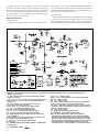
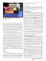
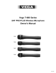
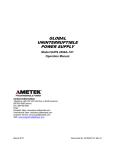
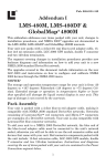
By Charles Kitchin, N1TEV A Simple Regen Radio for Beginners Need a simple, fun projectpossibly for a Scout Radio Merit Badge? This project is a great way to introduce kids of any age to electronics and shortwave listening. ere’s a low cost, simple-to-build, portable shortwave receiver. Its design is noncritical and the receiver is easy to get going. With it, you can receive dozens of international shortwave broadcast stations at night even indoorsusing a 39-inch whip antenna. This little radio is perfect for discovering ham-band QSOs, news, music and all the other things the shortwave bands have to offer. Although this little receiver is quite sensitive, it naturally won’t match the performance of a commercial HF rig, and if you’ve not used a regen before, you’ll have to practice tuning the radiobut that’s part of the adventure. Most of today’s experienced “homebrewers” got their start by building simple, fun circuits just like this one. You’ll gain experience in winding a coil and following a schematic. As your interest in radio communication develops, you can build a more complex receiver later. The little receiver requires only a single hand-wound coil and consumes just 5 mA from a 9-V battery. At that rate, an alkaline battery can provide approximately 40 hours of operation. The sound quality of this receiver is excellent when using Walkman headphones. The radio can also drive a small speaker. To simplify construction, a low-cost PC board is available from FAR circuits.1 You can house the receiver in a readily available RadioShack plastic project box. H In this version of the receiver, a prototype PC board is used; it is not directly representative of the currently produced board, although they are similar. In this view of the receiver, the antenna has been removed. The TUNING capacitor is at the left. Immediately behind the capacitor is the coil, L1. Attached between the TUNING capacitor and the VOLUME control pot immediately beneath you can see D1, C4 and R4 as discussed in the text. Circuit Description Take a look at the schematic in Figure 1. L1 and C1 tune the input signal from the whip antenna. Regenerative RF amplifier Q1 operates as a grounded-base Hartley oscillator. Its positive feedback provides a signal amplification of around 100,000. The combination of the very low operating power of this stage, only 30 µW, with the use of a simple whip antenna makes this receiver easily portable and prevents it from interfering with other receivers located nearby. Regenerative receivers are, after all, 1Notes appear on page 64. oscillators. R2 controls the amount of positive feedback (regeneration). D1 and C4 comprise a floating detector that provides high sensitivity with little loading of Q1. The relatively low back-resistance of the 1N34 germanium diode (don’t use a silicon diode here!) provides the necessary dc return path for the detector. VOLUME control R5 sets the level of detected audio driving U1, an LM386 audio amplifier. C5 provides low-pass filtering that keeps RF out of the audio amplifier. R4 isolates the low-pass filter from the detector circuit when the volume control is at the top of its range. The bottom of the VOLUME control, R5, and pin 3 of the LM386 float above ground so that both inputs of the IC are ac coupled. This allows the use of a 100-kΩ VOLUME control; this high resistance value prevents excessive loading of the detector. D5 protects the receiver from an incorrectly connected battery. L1 is wound on a standard 35-mm plastic film can or a 1-inchdiameter pill bottle. C1 can be any air-dielectric variable capacitor with a maximum capacitance of 100 to 365 pF. Total frequency coverage varies with the capacitance value used, but any capacitor in that range should cover the 40-meter ham band and several international broadcast bands. If you use a capacitor with a large capacitance range (such as 10 to 365 pF), you’ll find that selectivSeptember 2000 61 ity suffers. That is, it’s more difficult to tune in an individual station because there are more stations within the tuning range than when using a capacitor with a smaller capacitance range (such as 10 to 150 pF). Therefore, an optional fine-tuning control (see the inset of Figure 1) is recommended when using tuning capacitors with a wide capacitance range. Building the Receiver Finding the Parts Air-dielectric variable capacitors can be purchased from sev- eral suppliers.2 You can also find them at ham flea markets or salvage one from a discarded AM radio. All the other components are available from RadioShack and Digi-Key. PC boards are available from FAR Circuits (see Note 1). Winding the Coil Some would-be builders are intimidated by the idea of winding a coil. Actually it’s quite easy to do. Sometimes, having a second set of hands helps. For the coil winding, use 22-gauge solid-conductor insulated hook-up wire. Before you start winding the coil, Figure 1—Schematic of the simple regen receiver. Unless otherwise specified, resistors are 1/ 4-W, 5%-tolerance carboncomposition or metal-film units. Part numbers in parentheses are RadioShack. Equivalent parts can be substituted; n.c. indicates no connection. R1, R31 kΩ (RS 271-1321) C1150 to 350 pF (maximum value) air-dielectric variable R2, R5100 kΩ potentiometer, linear taper (RS 272-092) capacitor; see text. R422 kΩ (RS 271-1339) C2, C30.001 µF, 50 V (or more) disc ceramic (RS 272-126) R610 Ω (RS 271-1301) C4, C10, C11, C140.01 µF, 50 V (or more) disc ceramic R7150 kΩ (RSU11345287) or use series-connected 100 kΩ (RS 272-131) (RS 271-1347) and 47 kΩ (RS 271-1342) resistors. C50.002 µF, 50 V (or more) disc ceramic (use two R8100 kΩ audio-taper pot (RS 271-1722); connect so that RS 272-126 connected in parallel). clockwise rotation increases the voltage at the junction of C6, C90.047 µF, 50 V disc ceramic (RS 272-134) the pot arm, R9 and C14. C710 µF, 35 V electrolytic (RS 272-1025) R91 MΩ (RS 271-1356) C8220 µF, 35 V electrolytic (RS 272-1017) S1SPST miniature toggle (RS 275-612) C12, C1347 µF, 35 V electrolytic (RS 272-1027) U1LM386N-1 audio amplifier (RS 276-1731) C155 to 10 pF, 50 V (or more) mica (RS 272-120) Misc: PC board (see Note 1); 39-inch whip antenna D11N34A germanium diode (RS 276-1123); don’t use a (RS 270-1403); 8-pin DIP socket for U1 (RS 276-1995A); silicon diode here. 9-V battery clip (RS 270-325); three knobs (RS 274-402A); D2-D51N4148 or any similar silicon diode (RS 276-1122) project box (RS 270-1806); #6-32 screws and nuts, rubber D61N4003 silicon diode (RS 276-1102) 1 feet; 9-V battery, Radio Shack 22-gauge solid hook-up wire. J12 / 8-inch, three-circuit jack (RS 274-246) Note: RSU items in the RadioShack catalog need to be L1—See text. ordered (delivery in approximately 7 to 10 business days). Q12N2222A NPN transistor (RSU11328507) or MPS2222A (RS 276-2009) 62 September 2000 frequency range of the receiver. You can compensate for this by removing turns from L1 if necessary. Two-Band Option If you’d like a two-band receiver with noncritical tuning, use a 150-pF capacitor for C1 and install a miniature toggle switch with very short leads to add an additional 250-pF fixed-value mica capacitor in parallel with C1. With the capacitor in the circuit, the receiver will then tune the 80-meter band. Packaging the Radio This close-up shows the interconnection of seriesconnected D1, C4 and R4 between the TUNING capacitor and VOLUME control. drill a mounting hole in the bottom of the film can or pill bottle. Then, drill two small holes in the side of the coil form, near the top, where the winding starts. (By winding from the top of the coil form to the bottom, the winding bottom is kept well above the PC board, preventing any circuit loading that could decrease the receiver’s selectivity.) Feed one end of the coil wire through the first hole to the inside of the form, then out through the second. Tie a knot at the point in the wire where it enters the form—this keeps the wire in place and prevents it from loosening later on. Be sure to leave a two to three inch length of wire at each end of the coil so you can make connections to the PC board. You can wind the coil in either direction, clockwise or counterclockwise. Tightly wind the wire onto the form, counting the turns as you go. Keep the turns close together and don’t let the wire loosen as you wind; this takes a little practice. To make the coil tap, wind 11 turns on the coil form. While holding the wire with your thumb and index finger, mark the tap point and remove the insulation at that point. Solder a two to threeinch piece of wire to the tap. Continue winding turns until the coil is finished (13 turns total). Keep the free end of the wire in place using a piece of tape and drill two more holes in the coil form where the winding ends. Feed the wire end in and out of the coil as before and tie a knot at the end to hold the winding in place. When the coil is finished, remove the tape then carefully solder the three wires from the coil (bottom, tap and top) to their points on the PC board keeping the wire lengths as short as possible. For best performance, the floating detector must be wired using short, direct connections. Therefore, these components are not mounted on the PC board. Mount the VOLUME control, R5, close to the TUNING capacitor, C1. Connect D1, C4 and R4 in series between the hot side of C1 (the stator) and the top of the VOLUME control. Options Fine-Tuning Control You can add a fine-tuning control to the receiver using the circuit shown in the inset of Figure 1. D6 functions as a poor man’s Varactor (voltage-variable capacitor). As the voltage from FINETUNING control R8 is increased, the diode is reverse biased and its capacitance decreases. This fine-tuning control is cheap and easy to add, but its added capacitance somewhat reduces the maximum The recommended RadioShack project box includes metal and plastic tops. Use the metal top as a large front panel by mounting it to one side of the box using two small screws and nuts through two of the four predrilled holes. Then drill the control mounting holes and mount the three controls and the ON/OFF switch on the metal panel. The radio is easier to operate if you mount the TUNING capacitor and the regeneration ( REGEN) control on opposite sides of the front panel. The VOLUME and REGEN controls are best mounted near the bottom of the front panel to keep their connecting wires to the PC board as short as possible. You can use the RadioShack hook-up wire for the VOLUME and REGEN control connections if you twist the wires closely together and keep their lengths very short. Otherwise, use shielded wires for these connections. You can mount the ON/OFF switch last, in any convenient location. Use one of the two remaining holes in the metal front panel to attach a wire connecting the panel to the PC board ground. Attach the PC board and the coil to the bottom of the project box using small screws. Mount the headphone jack on the box rear, close to the PC board and the LM386. Attach the RadioShack 39-inch whip antenna to one of the back corners of the box using a small screw and nut. If you use the RadioShack jack specified for J1 (RS 274-276), connect together pins 2 and 5 and attach that common lead to C8. Ground pin 1 of the jack. If you intend to use a small speaker, connect it between pins 1 and 3. Then, when headphones are plugged in, the speaker will be disconnected automatically. Testing and Operating the Receiver Set the VOLUME and REGEN controls to midrange, plug in the headphones, extend the whip antenna, attach the battery and turn on the receiver. You can check to ensure that the audio stage is functioning by placing a finger on the center lug (wiper) of the VOLUME control and listen for a buzz. If the audio stage is working, adjust the REGEN control until the set produces a sound, indicating that Q1 is oscillating. If Q1 is not oscillating, carefully check the wiring and measure the voltages labeled on the schematic using a high-impedance DVM or multimeter. Common problems are Q1 being wired backwards (emitter and collector connections reversed) and the wires from coil L1 connected to the wrong places on the PC board. Use two hands when operating the receiver: one for tuning, the other for controlling regeneration. For international broadcast stations or AM phone operation on 40 meters, carefully adjust the REGEN control so that Q1 is just below oscillation. For CW and SSB, increase the REGEN level so that the set just oscillates providing the required local oscillation for these modes. This receiver picks up lots of stations with just its whip antenna, although using a ground connection will greatly reduce any hand-capacitance effects. To pull in more stations during daylight hours, a 10 to 15foot (or longer) length of insulated hook-up wire can be used as an external antenna. Simply wrap the end of this wire a couple of times around the whip antenna. If you operate this receiver close to another radio, the regen’s 30-µW oscillator might interfere with it. Those who are interested September 2000 63 in building a higher-performance regen receiver for serious CW and SSB reception should read my article “High Performance Regenerative Receiver Design.”3 You can also see the project at http://www.electronics-tutorials.com/receivers/regen-radio-receiver.htm Notes 1A PC board for this radio is available from FAR Circuits, 18N640 Field Ct, Dundee, IL 60118-9269, tel 847-836-9148 (voice and fax). Price: $5 each plus $1.50 shipping for up to three boards. FAR Circuits offers a group discount rate of 10% for orders of 10 or more boards. Visa and MasterCard accepted with a $3 service charge; [email protected]; http://www.cl.ais.net/ farcir/. 2Suppliers include, but are not limited to: Antique Electronics Supply, 7221 S Maple Ave, Tempe, AZ 85283; tel 480-820-5411, fax 800-706-6789, 480820-4643; [email protected]; http://www.tubesandmore.com; Digi-Key Corp, 701 Brooks Ave S, Thief River Falls, MN 56701-0677; tel 800344-4539, 218-681-6674, fax 218-681-3380; http://www.digikey .com; Fair Radio Sales Co, Inc, 1016 East Eureka St, PO Box 1105, Lima, OH 45804; NEW BOOKS THE LOGIC OF MICROSPACE By Rick Fleeter, K8VK Published jointly by Kluwer Academic Publishers and Microcosm Press. Available from Microcosm Press, 401 Coral Circle, El Segundo, CA 90245-4622; tel 310-726-4100; http://www.smad.com. 6×9 inches, 477 pages. Softcover. ISBN 1-881883-11-6. $29.95. Reviewed by Steve Ford, WB8IMY QST Managing Editor ◊ The Logic of Microspace has nothing to do with Amateur Radio—and everything to do with Amateur Radio. Hams pioneered the concept of microsatellites—compact spacecraft designed to be deployed at minimal cost while offering flexible functionality. The results are orbiting overhead as you read these words. Several of the first Amateur Radio microsats launched almost 10 years ago are still very much alive and well. Microsats have since moved into the commercial sphere with corporations, governments and even NASA embracing the concept. In fact, author Rick Fleeter, K8VK, is president and CEO of AeroAstro, a company that designs and builds microsats. But we still haven’t addressed the question of why you should be interested in reading The Logic of Microspace. There are two reasons: (1) To gain an education in the fascinating world of space technology in general and microsats in particular and, (2) because this book is a pure delight. Rick Fleeter is one of those rare individuals who can not only explain technical topics to any audience, he can do so with highly effective humor. This gifted combination of talent makes The Logic of Microspace one of the most unusual science and technology books you’ll ever read. Like his previous work, Micro Space Craft, The Logic of Microspace is the kind of title that seems deliberately designed to hide the true content of the book. If you saw The Logic of Microspace sitting on a bookstore shelf, chances are you’d stroll right by without giving it much more than a glance. (Oh, another one of those boring academic snoozers!) You couldn’t be more wrong. In The Logic of Microspace Fleeter takes complex topics such as rocket propulsion and orbital mechanics and explains them clearly, without patronizing. The Logic of Microspace eschews the stuffy traditions of academic and technical writing. (There isn’t a “hitherto” or a “thus” to be found.) Instead, The Logic of Microspace is totally conversational and often downright hilarious. Fleeter’s writing style is filled with contemporary references to pop culture (rock n’ roll in particular). Imagine a technical book 64 September 2000 tel 419-227-6573, 419-223-2196; fax 419-227-1313; e-mail fairadio@ wcoil.com; http://www.fairradio.com/; Ocean State Electronics, PO Box 1458, 6 Industrial Dr, Westerly, RI 02891; tel 800-866-6626, 401-596-3080, fax 401-596-3590; RadioShack—see your local distributor. RadioShack.com L. P., 300 West Third Street, Suite 1400, Fort Worth, TX 76102; http:// www.radioshack.com/; The Electronic Goldmine, PO Box 5408, Scottsdale, AZ; 85261; tel 800-445-0697; fax 480-661-8259; e-mail [email protected]; http://www.goldmine-elec.com. 3Charles Kitchin, N1TEV, “High Performance Regenerative Receiver Design,” QEX, Nov/Dec 1998, pp 24-36. See also Charles Kitchin, N1TEV, “Regenerative Receivers: Past And Present,” Communications Quarterly, Fall 1995, pp 7-26. 26 Crystal St Billerica, MA 01821 [email protected] written by a tag team of Carl Sagan, P. J. O’Rourke and Hunter Thompson and you’ll have a pretty good idea of what to expect with The Logic of Microspace. A glance at some of the chapter sections will give you a sense of the “atmosphere:” • Weather, Ecology And Another Proof of the Existence of God • How Mother Nature is Cruel to Eight-Year-Olds • A War Waged for the Sake of the Clueless (my personal favorite) The Logic of Microspace is really three books in one. The first is a treatise on space technology and physics. The second is a fascinating examination of the politics, planning and psychology that underlies much of the work involved in aerospace projects. The third is the biggest surprise of all—a work of science fiction. The 94-page novella is titled “A Wrinkle in Microspace” and it is as compelling as anything you’ll find on the fiction shelf of your local library. Although it may not be obvious, Amateur Radio illuminates every page of The Logic of Microspace. Insatible technical and scientific curiosity is what drove Rick Fleeter to become a ham in the first place. That same muse guided him later to a career in aerospace. The Logic of Microspace is, in many ways, a testimonial to the fundamental “spirit” that brings us all to this hobby—and carries some of us, such as Rick Fleeter, much farther. NEW PRODUCTS CAPANALYZER 88A IN-CIRCUIT CAPACITOR TESTER ◊ The CapAnalyzer 88A allows testing of electrolytic and tantalum capacitors in-circuit by measuring the equivalent series resistance (ESR) and the dc resistance (DCR)—eliminating the need to desolder the component from the pc board. The test instrument discharges the capacitor, checks it for low DCR, reads out the high-frequency ESR and allows you to quickly compare those readings with the industry standard values conveniently provided on a three-color chart on the front panel. There’s also a QuickESR mode to speed ESR-only testing and a 1- to 5-beep tone alert system that allows you to know the approximate ESR reading without having to avert your attention from the device under test. The included tweezer-type probe allows easy one-handed testing of both normal and surface-mounted capacitors and uses coaxial cable instead of separate test-probe wires, insuring stable readings even on small capacitors. The CapAnalyzer 88A is battery powered—an optional ac adapter is also available. For more information, visit your favorite electronics distributor or contact Electronic Design Specialists, Inc, 4647 Appalachian St, Boca Raton, FL 33428; tel/fax 561-487-6103; info@ eds-inc.com; http://www.edsinc.com/.