1
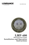
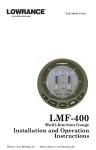
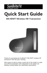
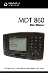
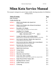
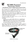
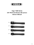
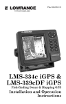
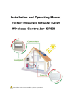
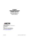
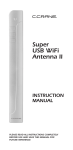
Pub. 988-0151-182
Addendum I
LMS-480M, LMS-480DF &
GlobalMap® 4800M
This addendum addresses new items packed with your unit, changes to
installation procedures, and NMEA 2000 ® upgrades not documented in
the LMS 480M, LMS-480cDF and GlobalMap 4800M manuals.
Your unit now packs with a 2-foot (61 cm) blue-to-red adapter cable, 15foot (4.6 m) extension cable, LGC-3000 GPS module, double T connector
and two 120-ohm terminators.
The segment covering changes in installation procedures provides new
backcase diagrams and information on how to add your unit to a new
NMEA 2000 standard DeviceNet network.
The upgrades covered in this document include information on the new
LGC-3000 and instructions on how to configure and calibrate NMEA
2000 devices through the NMEA 2000 menu.
NOTICE!
The storage and operation temperature range for your unit is from -20
degrees to +167 degrees Fahrenheit (-28 degrees to +75 degrees Celsius). Extended storage or operation in temperatures higher or lower
than specified will damage the liquid crystal display in your unit. This
type of damage is not covered by the warranty.
Pack Assembly
Your unit is packed with a 2-foot blue-to-red adapter cable, making it
compatible with NMEA 2000 standard DeviceNet networks. Networks
consisting of LowranceNet™ red connectors and Micro-C™ connectors
are examples of a DeviceNet network. Your unit is also compatible with
LowranceNet blue connector networks.
To add your unit to a NMEA 2000 DeviceNet network, the blue end of
the blue-to-red adapter cable must be connected to the unit's network
socket; otherwise you will not be able to use the red connector cables and
devices that came with your unit. Red connector components packed with
the unit include: 15-foot extension cable, LGC-3000 GPS module, double
T connector and two 120-ohm terminators. Instructions and diagrams
covering the use of items packed with your unit are contained in the Power
Connections segment below.
1
Power Connections
Your unit comes with a power/data cable that splits into three
branches, each with several exposed wires.
The thicker three-wire cable (white, red and black) is the power supply
for your display unit. This cable has no label.
The thinner branch with three wires (red, black and shield) is the
power cable for a NMEA 2000 network. It is labeled "NMEA 2000
POWER."
The branch with four wires (blue, yellow, orange, and shield) is a data
cable, labeled "RS-232 COMM." It supports a serial communication
port. This allows your unit to exchange NMEA 0183 data with another
device, such as an autopilot, DSC marine radio or computer.
NOTE:
There are two basic power connection options, which are shown in
the following two diagrams. Read the following instructions
carefully to determine which power connection applies to
your unit. Depending on your configuration, you may not use all of
these wires.
Display unit power wires:
white, red and black
To unit
NMEA 2000 power wires:
red, black and shield
Data cable wires:
blue, yellow, orange,
and shield
The Power/Data cable for this unit.
Caution:
All of the wires in the power/data cable have bare ends for easier installation. The bare ends on any unused wires could cause
an electrical short if left exposed. To prevent this, you should
cover the individual wire ends – either by capping them with
wire nuts, wrapping them with electrical tape or both. (You
should cut off the bare wire before taping off the ends.)
2
Powering Your Display Unit
The display unit works from a 12-volt DC battery system. Attach the
display power cable (with provided 3-amp fuse) to an accessory switch
or power bus. If this results in electrical interference, connect direct to
a battery but install an in-line switch on the cable.
Caution:
We strongly recommend that you shut off the power supply to the
power cable when the unit is not in use, especially in saltwater environments. When the unit is turned off but still connected to a
power supply, electrolysis can occur in the power cable plug. This
may result in corrosion of the plug body along with the electrical
contacts in the cable and the unit's power socket. Risk of electrolysis corrosion is even greater when the cable is unplugged from the
unit, but still connected to a power source. We recommend you
connect the power cable to the auxiliary power switch included
in most boat designs. If that results in electrical interference, or
if such a switch is not available, we recommend connecting direct to the battery and installing an in-line switch. This will let
you shut off power to the power cable when the unit is not in use.
When you are not using the unit, you should always shut off
power to the power cable, especially when the power cable is disconnected from the unit.
WARNING:
This product must be independently fused with the enclosed 3-amp fuse (or equivalent), even if you connect to
a fused accessory or power bus.
If a malfunction happens inside the unit, extensive damage can occur if the enclosed fuse is not used. As with all
electrical devices, this unit could be damaged to a point
that it is unrepairable and could even cause harm to the
user when not properly fused.
Failure to use a 3-amp fuse will void your warranty.
If possible, keep the power cable away from other boat wiring, especially
the engine's wires. This will provide the best isolation from electrical
noise. If the cable is not long enough, splice #18 gauge wire onto it.
The display power cable has three wires, white, red and black. Red is the
positive (+) lead, black is negative (–) or ground. The white wire is unused by your unit and should be capped. Make sure to attach the in-line
fuse holder to the red lead as close to the power source as possible.
3
For example, if you have to extend the power cable to the power bus or
battery, attach one end of the fuse holder directly to the power bus or
battery. This will protect both the unit and the power cable in the event
of a short.
This unit has reverse polarity protection. No damage will occur if the
power wires are reversed. However, the unit will not work until the
wires are attached correctly.
Power Diagram A
Mandatory
network
power-off
switch
To unit
3-amp fuse
NMEA 2000
Power Cable
Shield
Display Unit
Power Cable
3-amp fuse
Recommended
display unit
power-off switch
Black
Red
Black
White
(unused)
Data Cable
12 volt DC
power source
Use this method if you are powering the display unit and a GPS module or the display unit and a NMEA 2000 network. (Fuses may be different from those shown.)
The network and any NMEA 2000 devices, including the GPS
module, will not operate unless the NMEA 2000 Power Cable is
connected to power. The NMEA 2000 power cable must be connected
to power even if your only NMEA 2000 device is the GPS module and it
is connected to the display unit's Network socket. (However, never
connect multiple power sources to a NMEA 2000 network.
The method in diagram B is also used when your display unit is connected to a NMEA 2000 network that is already connected to power.
(Never connect multiple power sources to a NMEA 2000 network.)
4
Powering a NMEA 2000 Network Bus
A NMEA 2000 bus must be connected to a power source to operate.
NMEA 2000 devices, including GPS modules, draw their power from
the network bus. If you have a pre-existing NMEA 2000 network installation, it may already be connected to another power source. If you are
not sure about a network's power status, consult the boat manufacturer
or dealer. If your NMEA 2000 bus is already powered, you can ignore the
NMEA 2000 Power cable and use the method shown in Power Diagram
B. Never attach two power sources to a single NMEA 2000 bus.
Power Diagram B
To unit
White wire
(unused)
Display Unit
Power Cable
All unused Data
or NMEA 2000
power wires
should be
capped with
wire nuts and
electrical tape
to prevent
shorts.
Data Cable
Red wire with
3-amp fuse
Black wire
Recommended
power off switch
12 volt DC
power source
NMEA 2000 Power Cable
Use this method if you are only powering your display unit and are not
powering a NMEA 2000 network or any NMEA 2000 accessory device,
including a GPS module. (Fuse may be different from that shown.)
If you do need to power your NMEA 2000 bus, attach the NMEA 2000
Power cable to an accessory switch as indicated in power diagram A on
page 4. The NMEA 2000 Power cable's red wire should be attached
(with provided 3-amp fuse) to the positive (+) terminal. The NMEA
2000 Power cable's black and shield wires should both be attached to
the negative (–) terminal.
WARNING:
The NMEA 2000 network bus is always on and constantly
drawing power. You must connect NMEA power to a
switched power source so you can turn off the network
5
when not in use. Failure to connect to and use a power
switch will drain your boat battery, which could stop
your boat's operation.
GPS Antenna/Receiver Module
Your unit packs with the LGC-3000 GPS module. This device contains
the unit's external antenna and receiver for GPS and WAAS signals.
The antenna/receiver module comes with a 15-foot (4.6 m) extension
cable. This module can be mounted on a flat surface or pole, or an optional magnet is available for temporary mounting on any ferrous surface.
You need to select an antenna installation location that has a clear, unobstructed view of the sky. After the module is installed, connect it to the
unit. The LGC-3000 can communicate with your GPS unit either directly
(using the supplied extension cable) or through a NMEA 2000 network.
LGC-3000 Module, bottom view (left) and top view (right).
NOTE
See the module’s instruction sheet, publication part number 9880154-651, for complete installation instructions.
To use the module in an automobile, you may achieve good results by
simply placing the external antenna on the top of the dash, at the base of
the windshield. A piece of the rubber non-skid shelf liner material available in recreational vehicle supply stores will help hold the antenna in
place. This may not work well if you have a cab-over design pickup truck
camper or motor home. If dashboard reception is poor, simply relocate
the antenna module elsewhere on the vehicle for a clearer view of the
sky.
Connecting to a NMEA 2000 Network
A network bus is an installed and operational network cable (backbone)
running the length of your boat, already connected to a power supply and
properly terminated. Such a bus provides network connection nodes at
various locations around your boat. The NMEA 2000 network is similar to
6
the telephone wiring in a house. If you pick up a phone in your living room,
you can hear someone talking into the phone in the bedroom.
Lowrance and LEI provide all the cables you will need to create a NMEA
2000 network. Lowrance provides T connectors and extension cables so
you can add devices along the backbone wherever you want. Once you
have a working network, every sensor added will come with its own T
connector for easy expansion.
The simplest NMEA 2000 network is a GPS or sonar/GPS display unit
with the LGC-3000, one double-T connector, two 120 ohm terminators
and any extension cables needed to connect them.
It is easy to expand this network by removing a terminator from one end
of the double T connector, then inserting a new T connector or extension
cable between the double T connector and terminator (See the NMEA
200 network general information document that came with your unit for
more information). For more information on connecting your unit to an
existing NMEA 2000 network, see the NMEA 2000 Networks General Information document that was packed with your unit, publication part
number 988-0154-173.
NMEA 0183 Wiring
(Data cable)
To exchange NMEA 0183 data, this unit has one NMEA 0183 version
2.0 communication port. Com port one (Com-1) can be used to receive
NMEA format GPS data. The com port can also transmit NMEA format
GPS data to another device.
Com-1
To unit
Orange (Receive)
NMEA Transmit
Shield (Ground)
Ground
To Other
GPS Receiver
Com-1 wiring to receive NMEA position information
from some other GPS receiver.
Yellow (Transmit)
Com-1
To unit
Shield (Ground)
NMEA Receive
Ground
To Other
Device
Com-1 wiring to transmit NMEA position information
to another NMEA-compatible device.
The four wires for the com port are combined with the display unit
power cable and NMEA 2000 Power cable to form the power/data cable
(shown earlier). Com-1 uses the yellow wire to transmit, the orange
wire to receive and the shield wire for signal ground. Your unit does
not use the blue wire.
7
Network socket
Sonar socket
Power/Data socket
120 ohm terminator
120 ohm terminator
Speed
sensor
Double T
connector
Display unit
power cable
Data
cable
NMEA-2000
Power cable
Blue-to-red
adapter cable
Extension
cable
Transducer
LGC-3000
Cable connections for LMS-480M and LMS-480DF.
8
Network socket
120 ohm terminator
Power/Data socket
120 ohm terminator
Double T
connector
Extension
cable
Display unit
Data
power cable
cable
NMEA-2000
Blue-to-red
Power cable
adapter cable
LGC-3000
Cable connections for the GlobalMap 4800M.
9
NMEA 2000 Device Configuration
The NMEA 2000 menu on your display unit's main menu allows you to
configure, calibrate and monitor devices on a NMEA 2000 network. The
NMEA 2000 menu provides access to the Bus Setup, Fuel Management
and NMEA 2000 Alarms. You also can turn on/off Waypoint Sharing
and Backlight Synchronization from the NMEA 2000 menu.
NOTE:
The menus in your unit may differ slightly from the screen captures used in this document. Your unit, however, will perform the
same NMEA 2000 functions in a similar manner.
Bus Setup highlighted on the NMEA 2000 menu.
Bus Setup
Selecting Bus Setup from the NMEA 2000 menu gives you access to the
Bus Configuration menu and the NMEA Diagnostics and Ethernet Diagnostics pages. The Bus Configuration menu allows you to choose an
engine-tank configuration and manage devices on the network. When
the Bus Configuration menu is accessed, a list will appear of all NMEA
2000 devices on the network.
Bus Configuration menu (left). NMEA Diagnostics page (center).
Ethernet Diagnostics (right).
10
The NMEA Diagnostics page displays information about the performance of the network bus, keeping you updated on bus status, mode, errors and bus traffic. The Ethernet Diagnostics page keeps you updated
on the performance of an Ethernet connection (if applicable) supplying
information ranging from IP Address to upload and download rates
(bytes per second). To refresh either Diagnostics page, highlight the
PING ALL DEVICES button at the bottom of the page and press ENT.
The network devices list is located in the top half of the Bus Configuration menu. You can configure, calibrate and set alarms for devices accessed from the Bus Configuration menu network devices list.
The Engine-Tank Configuration and Tank Select menus as well as the
Tank Size dialog box are located on the bottom half of the Bus Configuration menu. The Set Configuration button — positioned next to the
engine-tank configuration menu — allows you to finalize a selected configuration.
Bus Configuration menu with list of network devices. Engine-Tank
Configuration and Tank Select menus are at the bottom of the screen.
NOTE:
If you have not used the LMF-200 or LMF-400 to choose an enginetank configuration for your vessel, you must use your display unit
to select a configuration.
Engine & Tank Configuration
The Engine-Tank configuration menu is located below the NMEA 2000
Devices list, but will only be accessible if a Suzuki engine Interface,
EP-10 Fuel Flow, EP-15 Fluid Level, EP-45 Pressure Sensor or EP-50
Storage Device are on the network. When choosing an engine-tank configuration you will use the Tank Select menu, Tank Size dialog box and
Set configuration button, all detailed below.
11
Tank Select
The Tank Select menu allows you to choose from up to three tanks
(Port, Center and Starboard), depending on the Engine-tank configuration that has been selected. This allows you to set up each tank individually.
Tank Size
The Tank Size menu allows you to input the size of a selected tank in
gallons. After selecting the desired tank from the Tank Select menu,
you are ready to enter the tank's size.
Set Configuration button
The Set Configuration button is used to finalize engine-tank configuration settings.
Setting Engine-Tank Configuration:
1. Press MENU| MENU, use ↓ ↑ to highlight NMEA 2000 and press ENT.
2. The NMEA 2000 menu will appear with five options: Bus Setup,
Fuel Management, NMEA 2000 Alarms, Waypoint Sharing and Backlight Synchronization. Choose BUS SETUP and press ENT.
1 Engine/1Tank highlighted on Engine and Tank Configuration
menu (left). Starboard highlighted on Tank Select menu (center).
Tank Size set to 40 gallons (right).
3. Select ENGINE & TANK CONFIG and press ENT, which will open the Engine
& Tank Configuration menu with the following configuration options: 1
Engine/1 Tank, 1 Engine/2 Tanks, 2 Engines/1 Tank, 2 Engines/2
Tanks, 3 Engines/1 Tank, 3 Engine/3 Tanks and Unconfigured Bus.
4. Choose the configuration that matches the number of engines and
tanks on your vessel and press ENT.
5. Highlight TANK SELECT and press ENT, which will open the Tank Select
menu.
6. Select the tank you want to set up and press ENT. Press → to highlight the Tank Size dialog box and press ENT.
12
7. Use ↓ ↑, ← → to input the capacity (gallons) of the tank you chose
from the Tank Select menu and press ENT.
8. Repeat Steps 5-7 for each remaining tank.
9. When all tanks have been configured, press the SET CONFIGURATION button. The following confirmation message will appear: Are you sure you
wish to change the bus configuration? Choose YES and press ENT, Press
EXIT to get back to the main display.
Device Configuration Menu
When a device is selected from the network devices list on the Bus Configuration menu, its Device Configuration menu will appear. Device
configuration menus vary among devices. Available functions on device
configuration menus allow you to change device names, tank sizes,
fluid types and provide access to the Advanced Options menu. We will
cover configuration and calibration later in this section.
If you do not have an EP-15 Fluid Level, EP-10 Fuel Flow or EP-20 Engine Interface on the network, the Bus Configuration menu will not
display the Engine-Tank Configuration menu, Tank Select menu, Tank
Size menu or Set Configuration button.
Device Information and Device Data
The Device information panel, located to the left of the Device Configuration menu, displays information on the selected device that includes,
software version, model, address, serial number, instance and current
status.
Device Data is shown in the Device Data window at the bottom of the
device configuration menu. The information displayed in the Device
Data window will vary among devices. If, for example, you are viewing
the device configuration menu for an EP-15 Fluid Level, the device
data window will include tank size and the amount of fuel left in the
tank.
13
The Device Data for an EP-10 Fuel Flow includes Fuel Rate (amount of
fuel burned per hour), Fuel Used, Trip Fuel Used and Seasonal Fuel
Used.
NOTE:
If, as in the graphic above, you do not have a Suzuki Engine Interface, EP-15 Fluid Level or EP-10 Fuel Flow on the network, the
Engine & Configuration menu, Tank Select menu, Tank Size dialog
and Set Configuration button will not be displayed on the Bus Configuration menu.
Fuel Management Menu
The Fuel Management menu gives you access to the following options:
Tank Location, Fuel Added, Add Fuel, Fill Tank, Engine Select, Reset
Calibration, Reset Trip and Reset Seasonal. Those options allow you to
configure, calibrate, reset calibration, reset trip fuel and reset seasonal
fuel for select NMEA 2000 devices. We will cover configuration and calibration procedures later in this section.
Fuel Management highlighted on the NMEA 2000 menu (left).
Fuel Management menu (right).
Tank Location
If you chose an engine-tank configuration with more than one tank, you
will be able to switch the tank location (configuration) in the Tank Location menu. When fuel is added to a tank, you will select the correct
tank from the Tank Location menu, then input the amount of fuel
added in the Fuel Added dialog box.
Fuel Added
Used in tandem with the Add Fuel command, the Fuel Added dialog
box allows you to input the amount of fuel added to the tank, when an
amount of fuel is added that does not fill up the tank.
14
Add Fuel
After entering the amount of fuel added to a tank in the Fuel Added
dialog, the Add Fuel command finalizes the entry of the data. Like the
Fuel Added dialog, the Add Fuel command will only be used when an
amount of fuel is added that does not fill up the tank.
Fill Tank
You will use the Fill Tank command when calibrating a fuel flow and
when filling up the tank without calibration.
Adding Fuel to Tank
Tank Location, Fuel Added and Add Fuel commands work together to
keep NMEA 2000 fuel data consistent with the actual amount of fuel
added to the fuel tank(s).
1. Press MENU|MENU, select NMEA 2000 and press ENT.
2. The NMEA 2000 menu will appear with five options: Bus Setup,
Fuel Management, NMEA 2000 Alarms, Waypoint Sharing and Backlight Synchronization. Select FUEL MANAGEMENT and press ENT.
3. Highlight TANK LOCATION and press ENT. The Tank Location menu will
appear with up to three options: Port, Center and Starboard.
4. Select the tank you added fuel to and press ENT.
5. Follow the steps below that apply to your tank.
If you filled up the tank:
A. Press the FILL TANK button and press ENT. The following message will
appear: Are you sure you wish to Fill Tank? Press ENT. Another message will appear: Do you wish to re-calibrate the device? Highlight NO
and press ENT.
If you did not fill up the tank:
B. Highlight FUEL ADDED and press ENT to access the FUEL ADDED dialog
box. Use ↑ ↓ , ← → to input the amount of fuel added to the tank and
press ENT. Select the ADD FUEL button and press ENT. The following message will appear: Are you sure you wish to Add Fuel? Highlight YES and
press ENT.
6. Press EXIT repeatedly to get back to the main display.
Engine Operations
The lower half of the Fuel Management menu contains the following
Engine Operation functions: Engine Select, Reset Calibration, Reset
Trip and Reset Seasonal.
Engine Select
Engine Select allows you to choose the desired engine when resetting
calibration, resetting trip fuel and resetting seasonal fuel.
15
To Reset Calibration:
Choosing the Reset Calibration command will switch fuel flow calibration settings back to factory defaults.
1. Press MENU|MENU, select NMEA 2000 and press ENT.
2. Highlight FUEL MANAGEMENT and press ENT. The Fuel Management
menu will appear.
3. Highlight to ENGINE SELECT and press ENT. Select the desired engine —
the engine attached to the desired fuel flow — and press ENT.
4. Highlight RESET CALIBRATION and press ENT. The following confirmation message will appear: Are you sure you wish to Reset Calibration?
Select YES and press ENT. Calibration settings for the selected fuel have
been returned to factory defaults.
To Reset Trip:
The Reset Trip function allows you to reset to zero the running total of
fuel used on a particular trip.
1. Press MENU|MENU, select NMEA 2000 and press ENT.
2. Highlight FUEL MANAGEMENT and press ENT. The Fuel Management
menu will appear.
3. Select RESET TRIP and press ENT. The following confirmation message
will appear: Are you sure you wish to Reset Trip? Highlight YES and
press ENT. The Trip Fuel Used figure has been reset to zero.
To Reset Seasonal:
Your unit can track fuel usage not only for trips, but also for entire seasons. The reset seasonal command allows you to reset to zero the running total of fuel used during a season.
1. 1. Press MENU|MENU, select NMEA 2000 and press ENT.
2. Highlight FUEL MANAGEMENT and press ENT. The Fuel Management
menu will appear.
3. Select RESET SEASONAL and press ENT. The following confirmation message will appear: Are you sure you wish to Reset Seasonal?
Highlight YES and press ENT. The Seasonal Fuel Used figure has been
reset to zero.
NMEA 2000 Alarms
The NMEA 2000 Alarms menu allows you to set Full and Empty fuel
alarms for the EP-10 Fuel Flow, EP-15 Fluid Level, EP-50 Storage Device and the Suzuki Engine Interface. The alarms may be set to a percentage (0-100%) of tank capacity.
16
The second tab at the top of the NMEA 2000 Alarms page is the Alarm
Status Tab. When an alarm has been set for a device, the alarm and its
current status will be shown on the Alarm Status window. To view the
Alarm Status window, highlight the Alarm Status tab and press ENT.
To set NMEA 2000 Alarm:
1. Press MENU|MENU, select NMEA 2000 and press ENT.
2. Highlight NMEA 2000 ALARMS and press ENT.
3. Highlight FLUID LEVEL DEVICE and press ENT. Use ↑ ↓ to select the device you want to set an alarm for and press ENT.
4. Highlight the ENABLED box next to the desired alarm (Full Alarm or
Empty Alarm) and press ENT to turn on the alarm.
5. To set the alarm percentage, press → to highlight PERCENT and press
ENT.
6. Use ↑ ↓, ← → to input the desired percentage and press ENT. Repeat
Steps 3-4 to set the other alarm.
7. Highlight SET CONFIGURATION and press ENT to finalize alarm settings.
Press EXIT repeatedly to get back to the main display.
NOTE:
To turn off (uncheck) an alarm, highlight its ENABLED BOX and press
ENTER.
Waypoint Sharing
Waypoint Sharing allows you to share a waypoint from one display unit
with display units across the network.
To turn on/off Waypoint Sharing:
1. Press MENU|MENU, select NMEA 2000 and press ENT.
2. Highlight WAYPOINT SHARING and press ENT which will turn on/off waypoint sharing.
3. Press EXIT repeatedly to get return to the main display.
Backlight Synchronization
The Backlight Synchronization command will keep all display unit
backlight levels consistent across the NMEA 2000 network. So, if you
set the backlight level to 75% on one display unit, all other units on the
network will automatically switch to the same setting.
To turn on/off Backlight Synchronization:
1. Press MENU|MENU, select NMEA 2000 and press ENT.
2. Highlight BACKLIGHT SYNCHRONIZATION and press ENT, which will turn
on/off Backlight Synchronization.
3. Press EXIT repeatedly to get back to the main display.
17
Configuring EP Sensors
All configurable devices are configured through their Device Configuration menus, which may be accessed through the network devices list on
the Bus Configuration menu.
EP-35 Temperature Configuration
To input Device Name:
1. Press MENU|MENU, use ↑ ↓ to select NMEA 2000 and press ENT. The
NMEA 2000 menu will appear with five options: Bus Setup, Fuel Management, NMEA 2000 Alarms, Waypoint Sharing and Backlight Synchronization.
2. Highlight BUS SETUP and press ENT, which will open the Bus Configuration menu. A list of network devices will be at the top of the page.
3. Select the temp sensor you want to rename and press ENT. The Device Configuration menu will appear with the Device Name dialog box
highlighted.
4. Press ENT and use ↑ ↓, ← → to input the desired name for the temp
sensor. Press ENT. Press EXIT repeatedly to get back to the main display.
To select Temp Type:
1. Press MENU|MENU, use ↑ ↓ to select NMEA 2000 and press ENT. The
NMEA 2000 menu will appear with five options: Bus Setup, Fuel Management, NMEA 2000 Alarms, Waypoint Sharing and Backlight Synchronization.
2. Highlight BUS SETUP and press ENT, which will open the Bus Configuration menu. A list of network devices will be at the top of the page.
3. Select the desired temp sensor and press ENT. The Device Configuration menu will appear.
4. Highlight TEMP TYPE and press ENT. The following list of Temp Types
will appear: Water, Outside, Inside, Engine Room, Cabin, Live Well,
Bait Well, Refigeration, Heating System and Unknown.
5. Highlight the desired Temp Type and press ENT. The following confirmation message will appear: Are you sure you wish to change this
device's configuration?
6. Highlight YES and press ENT. Press EXIT repeatedly to get back to the
main display.
Advanced Options menu
The Temp sensor Advanced Options menu contains two categories: Instance and Restore Defaults.
18
Instance
The Instance command is intended for use only by experienced NMEA
2000 network technicians. Instance allows network technicians to resolve certain electronic probe conflicts. This is most likely to occur if the
network includes LMF-200 or LMF-400 digital gauges, which support
the display of fewer electronic probes than your GPS or sonar/GPS unit.
If you want to use your unit in a network including one of these digital
gauges, you may need to consult customer service.
You should never need this command if you are connecting your unit to
a network with similar display units and/or a series of electronic
probes.
Restore Defaults
The Restore Defaults command allows you to reset an individual EP-35
Temp Sensor's settings to factory defaults. If, for example, you execute
the Restore Defaults command from your Water Temp's Advanced Options menu, only the settings for the Water Temp will be reset to factory defaults. Other temps on the network will not be affected.
To restore default settings:
1. Press MENU| MENU, use ↑ ↓ to select NMEA 2000 and press ENT. The
NMEA 2000 menu will appear with five options: Bus Setup, Fuel Management, NMEA 2000 Alarms, Waypoint Sharing and Backlight Synchronization.
2. Highlight BUS SETUP and press ENT, which will open the Bus Configuration menu. A list of network devices will be at the top of the page.
3. Select the desired temp sensor and press ENT. The Device Configuration menu will appear.
4. Highlight ADVANCED OPTIONS and press ENT.
5. Select RESTORE DEFAULTS and press ENT. The following message will
appear: Are you sure you wish to change this device's configuration?
6. Highlight YES and press ENT. Press EXIT repeatedly to get back to the
main display.
EP-10 Fuel Flow Configuration
To input Device Name:
1. Press MENU| MENU, use ↑ ↓ to select NMEA 2000 and press ENT. The
NMEA 2000 menu will appear with five options: Bus Setup, Fuel Management, NMEA 2000 Alarms, Waypoint Sharing and Backlight Synchronization.
2. Highlight BUS SETUP and press ENT, which will open the Bus Configuration menu. A list of network devices will be at the top of the page.
19
3. Select the fuel flow you want to rename and press ENT. The Device
Configuration menu will appear with the Device Name dialog box highlighted.
4. Press ENTER and use ↑ ↓, ← → to input the desired name for the fuel
flow. Press ENT. Press EXIT repeatedly to get back to the main display.
To select a Location:
1. Press MENU| MENU, use ↑ ↓ to select NMEA 2000 and press ENT. The
NMEA 2000 menu will appear with five options: Bus Setup, Fuel Management, NMEA 2000 Alarms, Waypoint Sharing and Backlight Synchronization.
2. Highlight BUS SETUP and press ENT, which will open the Bus Configuration menu. A list of network devices will be at the top of the page.
3. Select the desired fuel flow and press ENT. The Device Configuration
menu will appear.
4. Select LOCATION and press ENT, which will open the Location menu
with following options: Port, Center, Starboard and Unknown.
5. Highlight the desired location and press ENT. The following message
will appear: Are you sure you wish to change this device's configuration?
5. Select YES and press ENT. Press EXIT repeatedly to get back to the
main display.
Advanced Options menu
The Fuel Flow sensor Advanced Options menu contains two categories:
Instance and Restore Defaults.
Instance
The Instance command is intended for use only by experienced NMEA
2000 network technicians. Instance allows network technicians to resolve certain electronic probe conflicts. This is most likely to occur if the
network includes LMF-200 or LMF-400 digital gauges, which support
the display of fewer electronic probes than your GPS or sonar/GPS unit.
If you want to use your unit in a network including one of these digital
gauges, you may need to consult customer service. You should never
need this command if you are connecting your unit to a network with
similar display units and/or a series of electronic probes.
Restore Defaults
The Restore Defaults command allows you to reset an individual EP-10
Fuel Flow Sensor's settings to factory defaults. If, for example, you execute the Restore Defaults command from your Port Fuel Flow Advanced Options menu, only the settings for the Port Fuel Flow will be
reset to factory defaults. Other fuel flows on the network will not be
affected.
20
To restore default settings:
1. Press MENU| MENU, use ↑ ↓ to select NMEA 2000 and press ENT. The
NMEA 2000 menu will appear with five options: Bus Setup, Fuel Management, NMEA 2000 Alarms, Waypoint Sharing and Backlight Synchronization.
2. Highlight BUS SETUP and press ENT, which will open the Bus Configuration menu. A list of network devices will be at the top of the page.
3. Use ↑ ↓ to select the desired fuel flow and press ENT. The Device
Configuration menu will appear.
4. Highlight ADVANCED OPTIONS and press ENT.
5. Select RESTORE DEFAULTS and press ENT. The following message will
appear: Are you sure you wish to change this device's configuration?
6. Highlight YES and press ENT. Press EXIT repeatedly to get back to the
main display.
EP-15 Fluid Level Configuration
To input Device Name:
1. Press MENU| MENU, use ↑ ↓ to select NMEA 2000 and press ENT. The
NMEA 2000 menu will appear with five options: Bus Setup, Fuel Management, NMEA 2000 Alarms, Waypoint Sharing and Backlight Synchronization.
2. Highlight BUS SETUP and press ENT, which will open the Bus Configuration menu. A list of network devices will be at the top of the page.
3. Select a fluid level you want to rename and press ENT. The Device
Configuration menu will appear with the Device Name dialog box highlighted.
4. Press ENT and use ↑ ↓, ← → to input the desired name for the fluid
level. Press ENTER. Press EXIT repeatedly to get back to the main display.
To select Tank Instance (Location):
1. Press MENU| MENU, use ↑ ↓ to select NMEA 2000 and press ENT. The
NMEA 2000 menu will appear with five options: Bus Setup, Fuel Management, NMEA 2000 Alarms, Waypoint Sharing and Backlight Synchronization.
2. Highlight BUS SETUP and press ENT, which will open the Bus Configuration menu. A list of network devices will be at the top of the page.
3. Select the desired fluid level and press ENT. The Device Configuration menu will appear.
4. Highlight TANK INSTANCE and press ENT, which will open the Tank Instance menu with the following options: Tank 1, Tank 2, Tank 3 and
Unknown.
21
5. Select the desired Tank Instance (location) and press ENT. The following confirmation message will appear: Are you sure you wish to
change this device's configuration?
6. Highlight YES and press ENT. Press EXIT repeatedly to get back to the
main display.
To select Fluid Type:
1. Press MENU| MENU, use ↑ ↓ to select NMEA 2000 and press ENT. The
NMEA 2000 menu will appear with five options: Bus Setup, Fuel Management, NMEA 2000 Alarms, Waypoint Sharing and Backlight Synchronization.
2. Highlight BUS SETUP and press ENT, which will open the Bus Configuration menu. A list of network devices will be at the top of the page.
3. Select the desired fluid level and press ENT. The Fluid Level Device
Configuration menu will appear.
4. Press ↓ to FLUID TYPE and press ENT, which will open the Fluid Type
menu with the following options: Fuel, Water, Gray Water, Live Well,
Oil, Black Water and Unknown.
5. Select the desired fluid type and press ENT. The following message
will appear: Are you sure you wish to change this device's configuration?
6. Highlight YES and press ENT. Press EXIT repeatedly to get back to the
main display.
To input Tank Size:
1. Press MENU| MENU, use ↑ ↓ to select NMEA 2000 and press ENT. The
NMEA 2000 menu will appear with five options: Bus Setup, Fuel Management, NMEA 2000 Alarms, Waypoint Sharing and Backlight Synchronization.
2. Highlight BUS SETUP and press ENT, which will open the Bus Configuration menu. A list of network devices will be at the top of the page.
3. Select the desired fluid level and press ENT. The Fluid Level Device
Configuration menu will appear.
4. Highlight TANK SIZE and press ENT. Use ↑ ↓ ,← → to input the size of
the tank and press Enter. The following message will appear: Are you
sure you wish to change this device's configuration?
5. Select YES and press ENT. Press EXIT repeatedly to get back to the
main display.
Advanced Options menu
The Fuel Flow sensor Advanced Options menu contains two categories:
Instance and Restore Defaults.
22
Instance
The Instance command is intended for use only by experienced NMEA
2000 network technicians. Instance allows network technicians to resolve certain electronic probe conflicts. This is most likely to occur if the
network includes LMF-200 or LMF-400 digital gauges, which support
the display of fewer electronic probes than your GPS or sonar/GPS unit.
If you want to use your unit in a network including one of these digital
gauges, you may need to consult customer service.
You should never need this command if you are connecting your unit to
a network with similar display units and/or a series of electronic
probes.
Restore Defaults
The Restore Defaults command allows you to reset an individual EP-15
Fluid Level Sensor's settings to factory defaults. If, for example, you
execute the Restore Defaults command from your Gray Water Fluid
Level Advanced Options menu, only the settings for the Gray Water
Fluid Level will be reset to factory defaults. Other fluid levels on the
network will not be affected.
To restore default settings:
1. Press MENU| MENU, use ↑ ↓ to select NMEA 2000 and press ENT. The
NMEA 2000 menu will appear with five options: Bus Setup, Fuel Management, NMEA 2000 Alarms, Waypoint Sharing and Backlight Synchronization.
2. Highlight BUS SETUP and press ENT, which will open the Bus Configuration menu. A list of network devices will be at the top of the page.
3. Select the desired fluid level and press ENT. The Device Configuration menu will appear.
4. Highlight ADVANCED OPTIONS and press ENT.
5. Select RESTORE DEFAULTS and press ENT. The following message will
appear: Are you sure you wish to change this device's configuration?
6. Highlight YES and press ENT. Press EXIT repeatedly to get back to the
main display.
NOTE:
The Fluid Level Device Configuration menu also contains the Calibrate button, but we will address that later in the segment covering
Calibration.
23
Suzuki Engine Interface Configuration
To input Device Name:
1. Press MENU| MENU, use ↑ ↓ to select NMEA 2000 and press ENT. The
NMEA 2000 menu will appear with five options: Bus Setup, Fuel Management, NMEA 2000 Alarms, Waypoint Sharing and Backlight Synchronization.
2. Highlight BUS SETUP and press ENT, which will open the Bus Configuration menu. A list of network devices will be at the top of the page.
3. Use ↑ ↓ to select the engine interface you want to rename and press
ENT. The Device Configuration menu will appear with the Device Name
dialog box highlighted.
4. Press ENT and use ↑ ↓, ← → to input a name for the interface. Press
ENT. Press EXIT repeatedly to return to the main display.
To select a Location:
1. Press MENU| MENU, use ↑ ↓ to select NMEA 2000 and press ENT. The
NMEA 2000 menu will appear with five options: Bus Setup, Fuel Management, NMEA 2000 Alarms, Waypoint Sharing and Backlight Synchronization.
2. Highlight BUS SETUP and press ENT, which will open the Bus Configuration menu. A list of network devices will be at the top of the page.
3. Select the desired engine interface and press ENT. The Device Configuration menu will appear.
4. Highlight LOCATION and press ENT, which will open the Location menu
with the following options: Port, Center, Starboard and Unknown.
5. Select the desired location and press ENT. The following confirmation
message will appear: Are you sure you wish to change this device's configuration?
6. Press ENT. Press EXIT repeatedly to get back to the main display.
To select Engine Type:
1. Press MENU| MENU, use ↑ ↓ to select NMEA 2000 and press ENT. The
NMEA 2000 menu will appear with five options: Bus Setup, Fuel Management, NMEA 2000 Alarms, Waypoint Sharing and Backlight Synchronization.
2. Highlight BUS SETUP and press ENT, which will open the Bus Configuration menu. A list of network devices will be at the top of the page.
3. Use ↑ ↓ to select the desired engine interface and press ENT. The Device Configuration menu will appear.
4. Highlight ENGINE TYPE and press ENT, which will open the Engine
Type menu with the following options: DF40, DF50, DF60, DF70,
DF90/115, DF140, DF150, DF175, DF200/225, DF250 and DF300.
24
5. Select your engine type and press ENT. The following message will
appear: Are you sure you wish to change this device's configuration?
6. Highlight YES and press ENT. Press EXIT repeatedly to get back to the
main display.
Advanced Options menu
The Engine Interface Advanced Options menu contains three categories: Instance, Restore Defaults and Reset Trim Calibration.
Instance
The Instance command is intended for use only by experienced NMEA
2000 network technicians. Instance allows network technicians to resolve certain electronic probe conflicts. This is most likely to occur if the
network includes LMF-200 or LMF-400 digital gauges, which support
the display of fewer electronic probes than your GPS or sonar/GPS unit.
If you want to use your unit in a network including one of these digital
gauges, you may need to consult customer service. You should never
need this command if you are connecting your unit to a network with
similar display units and/or a series of electronic probes.
Restore Defaults
The Restore Defaults command allows you to reset an individual engine interface's settings to factory defaults. If, for example, you execute
the Restore Defaults command from your Port Engine Interface Advanced Options menu, only the settings for the Port Engine Interface
will be reset to factory defaults. Other engine interfaces on the network
will not be affected.
To restore default settings:
1. Press MENU| MENU, use ↑ ↓ to select NMEA 2000 and press ENT. The
NMEA 2000 menu will appear with five options: Bus Setup, Fuel Management, NMEA 2000 Alarms, Waypoint Sharing and Backlight Synchronization.
2. Highlight BUS SETUP and press ENT.
3. Use ↑ ↓ to select the desired fluid level and press ENT. The Device
Configuration menu will appear.
4. Highlight ADVANCED OPTIONS and press ENT.
5. Select RESTORE DEFAULTS and press ENT. The following message will
appear: Are you sure you wish to change this device's configuration?
6. Highlight YES and press ENT. Press EXIT repeatedly to get back to the
main display.
25
NOTE:
The Suzuki Engine Interface Device Configuration menu contains
two Engine Trim calibration commands, which will be addressed in
the next segment of this section, Calibrating EP Sensors.
Calibrating EP Sensors
The factory calibration settings for the EP-10 Fuel Flow, EP-15 Fluid
Level and Suzuki Engine Interface should be adequate for the majority
of applications, so calibration will not be necessary in most cases.
EP-10 Fuel Flow Calibration
The default calibration for the EP-10 Fuel Flow is adequate in most
cases, but if Fuel Used readings are off by more than 3 percent, calibration is recommended.
To check fuel flow accuracy:
Select Fuel Used to be shown as Overlay Data on your unit's main display. Refer to the Overlay Data segment of this manual for instructions
on how to select Fuel Used data as Overlay Data.
1. After selecting Fuel Used as overlay data, fill up your tank and press
MENU|MENU.
2. Select NMEA 2000 and press ENT.
3. Highlight FUEL MANAGEMENT and press ENT. Select TANK LOCATION and
press ENT.
4. Use ↑ ↓ to select the location (Port, Center or Starboard) of the fuel
flow you want to calibrate and press ENT.
5. Highlight FILL TANK and press ENT. The following confirmation message will appear: Are you sure you wish to Fill Tank?
6. Select YES and press ENT. The following confirmation message will
appear: Do you wish to re-calibrate the device?
7. Highlight NO and press ENT.
8. Take your vessel out on the water and burn at least five gallons of
fuel. Be sure you run only ONE engine — the engine connected
to your fuel flow.
9. Fill up your tank again, noting how much fuel you added to the tank.
Compare that number to the Fuel Used figure displayed on the page
you customized. If the amount of fuel you added to the tank and the
fuel used figure are off by more than 3 percent, we recommend the fuel
flow be calibrated.
NOTE:
You must use the gauge's Fill Tank command when filling your fuel
tank to keep the fuel flow updated with correct information on the
amount of fuel in the tank.
26
To calibrate an EP-10 Fuel Flow:
10. If calibration is necessary, press MENU|MENU, select NMEA 2000 and
press ENT.
11. Highlight FUEL MANAGEMENT and press ENT.
12. Select TANK LOCATION and press ENT to choose the location of the tank
connected to selected fuel flow. Press ENT.
13. Highlight FILL TANK and press ENT. The following message will appear: Are you sure you wish to Fill Tank? Select YES and press ENT.
14. The following message will appear: Do you wish to re-calibrate the
device? Select YES and press ENT.
15. Repeat these steps for each EP-10 Fuel Flow you want to calibrate.
To Reset Calibration:
1. Press MENU|MENU, select NMEA 2000 and press ENT.
2. Highlight FUEL MANAGEMENT and press ENT.
3. Highlight ENGINE SELECT and press ENT. The Engine Select menu will
appear with up to four options: All Engines, Port, Center and Starboard. Selecting All Engines will reset calibration for all engines back
to factory defaults.
4. Select All Engines or the engine connected to the desired device and
press ENT.
5. Highlight RESET CALIBRATION and press ENT. The following message
will appear: Are you sure you wish to Reset Calibration?
6. Highlight YES and press ENT. Press EXIT repeatedly to get back to the
main display.
EP-15 Fluid Level Calibration
The default calibration for the EP-15 Fluid Level is just as accurate as
standard fluid level gauges. If, however, the tank has an irregular
shape or greater accuracy is needed, calibration is recommended. There
are three calibration options: 2-Point, 3-Point and 5-Point.
2-Point Calibration
A 2-point calibration is best suited for rectangular or square-shaped
tanks, where the capacity of the top half of the tank matches the capacity in the lower half of the tank. In a two-point calibration, you will set
two points, one each for empty and full levels. You can begin calibration at either of the two points, but we recommend starting with an
empty tank. You will fill the tank to complete calibration.
1. Press MENU| MENU, use ↓ ↑ to select NMEA 2000 and press ENT.
2. Highlight BUS SETUP and press ENT, which will open the Bus Configuration menu. A list of network devices will be at the top of the page.
27
3. Select the EP-15 Fluid Level and press ENT.
4. Press ↓ to select CALIBRATE and press ENT. The Device Calibration
menu will appear. Instructions on Calibration will be listed at the top
of the menu.
5. Highlight NUM PTS, press ENT and select 2. Press ENT.
6. Select FLUID LEVEL, press ENT, then select EMPTY LEVEL and press ENT.
Calibrate is highlighted on the device configuration menu (left). Calibration menu (right) with calibration instructions listed at the top.
7. Make sure the fuel tank is empty, highlight CALIBRATE and press ENT.
The following message will appear: Empty Level Calibration Completed. Press ENT.
8. Fill up your tank, highlight FLUID LEVEL and press ENT.
9. Select FULL LEVEL and press ENT. Highlight CALIBRATE and press ENT.
10. The following message will appear: Full level Calibration Completed. Press ENT, then press EXIT repeatedly to get back to the main
display.
3-Point Calibration
3-point calibration is designed for tanks that vary in shape from the top
to the bottom. You can begin calibration at any point in the 3-point
process, but we recommend starting calibration with an empty tank.
In a 3-point calibration, you will set three points, one each for empty,
half and full levels.
1. Press MENU| MENU, use ↓ ↑ to select NMEA 2000 and press ENT.
2. Highlight BUS SETUP and press ENT, which will open the Bus Configuration menu. A list of network devices will be at the top of the page. 3.
Select the EP-15 Fluid Level and press ENT.
28
4. Press ↓ to select CALIBRATE and press ENT. The Device Calibration
menu will appear.
5. Highlight NUM PTS, press ENT and select 3. Press ENT.
6. Make sure your tank is empty, then highlight FLUID LEVEL and press
ENT. Select EMPTY LEVEL and press ENT.
7. Select CALIBRATE and press ENT. The following message will appear:
Empty Level Calibration Completed. Press ENTER.
8. Add half a tank of fuel, highlight FLUID LEVEL and press ENT. Select
HALF LEVEL and press ENT.
Num Pts menu with 5-point calibration selected (left). Half level selected on
Fluid Level menu (center). Calibration Done window (right).
9. Select CALIBRATE and press ENT. The following message will appear:
Half Level Calibration Completed. Press ENT.
10. Fill up the tank, then highlight FLUID LEVEL and press ENT. Select
FULL LEVEL and press ENT.
11. Highlight CALIBRATE and press ENT. The following message will appear: Full Level Calibration Completed. Press ENT, then press EXIT re-
peatedly to get back to the main display.
5-Point Calibration
5-point calibration is best suited tanks that vary greatly in shape from
top to bottom. You can begin calibration at any point in the 5-point calibration process. We recommend starting calibration with an empty
tank. In a five-point calibration you will set five points: Empty Level, 1
Qtr Level, Half Level, 3 Qtr Level and Full Level.
In a 5-point calibration, you will have four calibration points left after
calibrating your tank's Empty Level. To figure out how much fuel you
should add for the remaining steps of the calibration process, divide the
total capacity of you tank by four. So, if you have a 40-gallon tank, each
quarter tank will equate to 10 gallons.
29
1. Press MENU| MENU, use ↓ ↑ to select NMEA 2000 and press ENT.
2. Highlight BUS SETUP and press ENT, which will open the Bus Configuration menu. A list of network devices will be at the top of the page.
3. Select the desired EP-15 Fluid Level and press ENT.
4. Press ↓ to select CALIBRATE and press ENT. The Device Calibration
menu will appear.
5. Highlight NUM PTS, press ENT and select 5. Press ENT.
6. Make sure your tank is empty, then highlight FLUID LEVEL and press
ENT. Select EMPTY LEVEL and press ENT.
7. Select CALIBRATE and press ENT. The following message will appear:
Empty Level Calibration Completed. Press ENT.
8. Add 1 quarter tank of fuel, highlight FLUID LEVEL and press ENT. Select
1 QTR LEVEL and press ENT.
9. Select CALIBRATE and press ENT. The following message will appear: 1
Qtr Level Calibration Completed. Press ENT.
10. Add another quarter tank of fuel, which should raise the fuel level
to half a tank. Highlight FLUID LEVEL and press ENT. Select HALF LEVEL and
press ENT.
11. Highlight CALIBRATE and press ENT. The following message will appear: Half Level Calibration Completed. Press ENT.
12. Add another quarter tank of fuel, which should raise the fuel level
to 3 quarters of a tank. Highlight FLUID LEVEL and press ENT. Select 3 QTR
LEVEL and press ENT.
13. Select CALIBRATE and press ENT. The following message will appear: 3
Qtr Level Calibration Completed. Press ENT.
14. Top off the tank, highlight FLUID LEVEL and press ENT. Select FULL
LEVEL and press ENT.
15. Select CALIBRATE and press ENT. The following message will appear:
Full Level Calibration Completed. Press ENT, then press EXIT repeatedly to get back to the main display.
Fuel Flow Calibration in a Suzuki Engine Interface
The default calibration for the Suzuki Engine Interface is adequate in
most cases, but if Fuel Used readings are off by more than 3 percent,
calibration is recommended.
To check engine interface accuracy:
Select Fuel Used to be shown as Overlay Data on your unit's main display. Refer to the Overlay Data segment of this manual for instructions
on how to select Fuel Used data as Overlay Data.
30
1. After selecting Fuel Used as overlay data, fill up your tank and press
MENU|MENU.
2. Select NMEA 2000 and press ENT.
3. Highlight FUEL MANAGEMENT and press ENT. Select TANK LOCATION and
press ENT.
4. Use ↑ ↓ to select the location (Port, Center or Starboard) of the engine interface you want to calibrate and press ENT.
5. Highlight FILL TANK and press ENT. The following confirmation message will appear: Are you sure you wish to Fill Tank?
6. Select YES and press ENTER. The following confirmation message will
appear: Do you wish to re-calibrate the device?
7. Highlight NO and press ENT. Take your vessel out on the water and
burn at least five gallons of fuel. Be sure you run only ONE engine
— the engine connected to your engine interface.
9. Fill up your tank again, noting how much fuel you added to the tank.
Compare that number to the Fuel Used figure displayed on the page
you customized. If the amount of fuel you added to the tank and the
fuel used figure are off by more than 3 percent, we recommend the engine interface be calibrated.
NOTE:
You must use the gauge's Fill Tank command when filling your fuel
tank to keep the engine interface updated with correct information
on the amount of fuel in the tank.
To calibrate a Suzuki Engine Interface:
10. If calibration is necessary, press MENU|MENU, select NMEA 2000 and
press ENT.
11. Highlight FUEL MANAGEMENT and press ENT.
12. Select TANK LOCATION and press ENT to choose the location of the tank
connected to the selected engine interface. Press ENT.
13. Highlight FILL TANK and press ENT. The following message will appear: Are you sure you wish to Fill Tank? Select YES and press ENT.
14. The following message will appear: Do you wish to re-calibrate the
device? Select YES and press ENT.
15. Repeat these steps for each engine interface you want to calibrate.
Engine Trim Calibration
Engine Trim is calibrated through the Suzuki Engine Interface Device
Configuration menu.
1. Press MENU|MENU, select NMEA 2000 and press ENT.
2. Choose BUS SETUP and press ENTER. Select the Suzuki Engine Interface connected to the desired engine and press ENT.
31
3. Highlight CALIBRATE TRIM and press ENT. The Device Calibration window will appear with a list of Calibration Instructions.
4. Highlight START CALIBRATION and press ENT. The following message
will appear: Please fully raise the Engine Trim.
5. After engine trim has been fully raised, press ENT. The following
message will appear: Please fully lower the Engine trim.
6. After engine trim has been fully lowered, press ENT. A Calibration
Completed message will appear. Press ENT.
7. Repeat these instructions to adjust the engine trim for each engine
connected to a Suzuki Engine Interface. Press EXIT repeatedly to return
to the main display.
Reset Trim Calibration
If you are not satisfied with your engine trim calibration, you can reset
engine trim calibration from the Suzuki Engine Interface Advanced
Options menu.
1. Press MENU|MENU, select NMEA 2000 and press ENT.
2. Choose BUS SETUP and press ENT. Select the Suzuki Engine Interface
connected to the desired engine and press ENT.
3. Highlight ADVANCED OPTIONS and press ENT. Select Reset TRIM CALIBRATION and press ENT. The following message will appear: Do you wish to
re-calibrate the device?
4. Highlight YES and press ENT. Press EXIT repeatedly to get back to the
main display.
Bennett Trim Tabs Calibration
Trim Tabs will be calibrated through their Device Configuration menu.
To calibrate Trim Tabs:
1. Press MENU|MENU, select BUS SETUP and press ENT. A list of network
devices will appear.
2. Select BENNETT TRIM TABS from the list and press ENT, which will open
the Trim Tab Device Configuration menu.
3. Highlight CALIBRATE and press ENT. The Device Calibration window
will appear with a list of calibration instructions.
4. Select START CALIBRATION and press ENT. The following message will
appear: Please fully raise Trim Tabs.
5. After fully raising the trims tabs, press ENT. The following message
will appear: Please fully lower trim tabs.
6. After fully lowering the trim tabs, press ENT. A Calibration Complete
message will appear. Press ENT. Press EXIT repeatedly to return to the
main display.
32
Reset Calibration highlighted (left). Reset Calibration confirmation
window (right).
To Reset Calibration:
1. Press MENU|MENU, select NMEA 2000 and press ENT.
2. Highlight FUEL MANAGEMENT and press ENT.
3. Highlight ENGINE SELECT and press ENT. The Engine Select menu will
appear with up to four options: All Engines, Port, Center and Starboard. Selecting All Engines will reset calibration for all engines back
to factory defaults.
4. Select All Engines or the engine connected to the desired device and
press ENT.
5. Highlight RESET CALIBRATION and press ENT. The following message
will appear: Are you sure you wish to Reset Calibration?
6. Highlight YES and press ENT. Press EXIT repeatedly to get back to the
main display.
33
Notes
34
Notes
35
Visit our web site:
Lowrance Pub. 988-0151-182
© Copyright 2006
All Rights Reserved
Lowrance Electronics, Inc.
Printed in USA 122206
36